installation - hussmanncabinets designed for pre-packaged ice cream, ice cream novelties, and frozen...
TRANSCRIPT
®
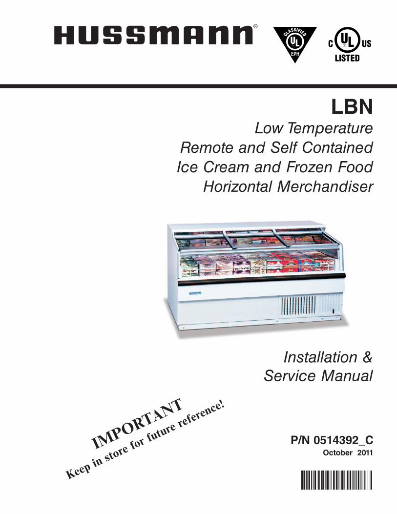
LBNLow Temperature
Remote and Self Contained Ice Cream and Frozen Food
Horizontal Merchandiser
Installation & Service Manual
P/N 0514392_COctober 2011
P/N0514392_B
IMPORTA
NT
Keep in
store f
or futur
e refere
nce!

P/N 0514392_C iii
IMPORTANTKEEP IN STORE FOR FUTURE REFERENCE
Quality that sets industry standards!
12999 St. Charles Rock Road • Bridgeton, MO 63044-2483
U.S. & Canada 1-800-922-1919 • Mexico 1-800-522-1900
www.hussmann.com© 2011 Hussmann Corporation
®

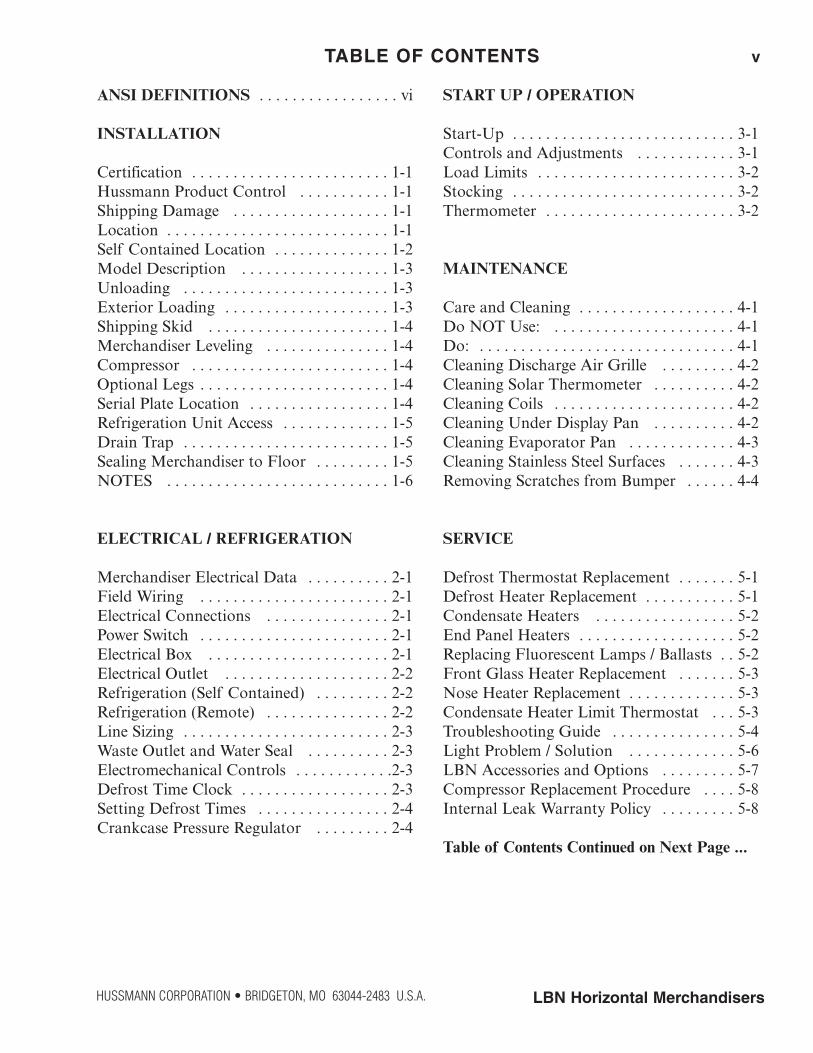
ANSI DEFINITIONS . . . . . . . . . . . . . . . . . vi
INSTALLATION
Certification . . . . . . . . . . . . . . . . . . . . . . . . 1-1Hussmann Product Control . . . . . . . . . . . 1-1Shipping Damage . . . . . . . . . . . . . . . . . . . 1-1Location . . . . . . . . . . . . . . . . . . . . . . . . . . . 1-1Self Contained Location . . . . . . . . . . . . . . 1-2Model Description . . . . . . . . . . . . . . . . . . 1-3Unloading . . . . . . . . . . . . . . . . . . . . . . . . . 1-3Exterior Loading . . . . . . . . . . . . . . . . . . . . 1-3Shipping Skid . . . . . . . . . . . . . . . . . . . . . . 1-4Merchandiser Leveling . . . . . . . . . . . . . . . 1-4Compressor . . . . . . . . . . . . . . . . . . . . . . . . 1-4Optional Legs . . . . . . . . . . . . . . . . . . . . . . . 1-4Serial Plate Location . . . . . . . . . . . . . . . . . 1-4Refrigeration Unit Access . . . . . . . . . . . . . 1-5Drain Trap . . . . . . . . . . . . . . . . . . . . . . . . . 1-5Sealing Merchandiser to Floor . . . . . . . . . 1-5NOTES . . . . . . . . . . . . . . . . . . . . . . . . . . . 1-6
ELECTRICAL / REFRIGERATION
Merchandiser Electrical Data . . . . . . . . . . 2-1Field Wiring . . . . . . . . . . . . . . . . . . . . . . . 2-1Electrical Connections . . . . . . . . . . . . . . . 2-1Power Switch . . . . . . . . . . . . . . . . . . . . . . . 2-1Electrical Box . . . . . . . . . . . . . . . . . . . . . . 2-1Electrical Outlet . . . . . . . . . . . . . . . . . . . . 2-2Refrigeration (Self Contained) . . . . . . . . . 2-2Refrigeration (Remote) . . . . . . . . . . . . . . . 2-2Line Sizing . . . . . . . . . . . . . . . . . . . . . . . . . 2-3Waste Outlet and Water Seal . . . . . . . . . . 2-3Electromechanical Controls . . . . . . . . . . . .2-3Defrost Time Clock . . . . . . . . . . . . . . . . . . 2-3Setting Defrost Times . . . . . . . . . . . . . . . . 2-4Crankcase Pressure Regulator . . . . . . . . . 2-4
START UP / OPERATION
Start-Up . . . . . . . . . . . . . . . . . . . . . . . . . . . 3-1Controls and Adjustments . . . . . . . . . . . . 3-1Load Limits . . . . . . . . . . . . . . . . . . . . . . . . 3-2Stocking . . . . . . . . . . . . . . . . . . . . . . . . . . . 3-2Thermometer . . . . . . . . . . . . . . . . . . . . . . . 3-2
MAINTENANCE
Care and Cleaning . . . . . . . . . . . . . . . . . . . 4-1Do NOT Use: . . . . . . . . . . . . . . . . . . . . . . 4-1Do: . . . . . . . . . . . . . . . . . . . . . . . . . . . . . . . 4-1Cleaning Discharge Air Grille . . . . . . . . . 4-2Cleaning Solar Thermometer . . . . . . . . . . 4-2Cleaning Coils . . . . . . . . . . . . . . . . . . . . . . 4-2Cleaning Under Display Pan . . . . . . . . . . 4-2Cleaning Evaporator Pan . . . . . . . . . . . . . 4-3Cleaning Stainless Steel Surfaces . . . . . . . 4-3Removing Scratches from Bumper . . . . . . 4-4
SERVICE
Defrost Thermostat Replacement . . . . . . . 5-1Defrost Heater Replacement . . . . . . . . . . . 5-1Condensate Heaters . . . . . . . . . . . . . . . . . 5-2End Panel Heaters . . . . . . . . . . . . . . . . . . . 5-2Replacing Fluorescent Lamps / Ballasts . . 5-2Front Glass Heater Replacement . . . . . . . 5-3Nose Heater Replacement . . . . . . . . . . . . . 5-3Condensate Heater Limit Thermostat . . . 5-3Troubleshooting Guide . . . . . . . . . . . . . . . 5-4Light Problem / Solution . . . . . . . . . . . . . 5-6LBN Accessories and Options . . . . . . . . . 5-7Compressor Replacement Procedure . . . . 5-8Internal Leak Warranty Policy . . . . . . . . . 5-8
Table of Contents Continued on Next Page ...
TABLE OF CONTENTS v
HUSSMANN CORPORATION • BRIDGETON, MO 63044-2483 U.S.A. LBN Horizontal Merchandisers

TABLE OF CONTENTS CONTINUED
APPENDIX
Part Numbers . . . . . . . . . . . . . . . . . . . . . . A-1Plan View . . . . . . . . . . . . . . . . . . . . . . . . . A-4Cross Section and Refrigeration Data . . . A-5Electrical Data . . . . . . . . . . . . . . . . . . . . . A-6Wiring Diagram LBN-4 . . . . . . . . . . . . . . A-7Wiring Diagram LBN-6 . . . . . . . . . . . . . . A-8Wiring Diagram LBN-7, 8 . . . . . . . . . . . . A-9Wiring Diagram LBN-10 . . . . . . . . . . . . A-10
REVISION HISTORY
REVISION C — Revised incorrect part number forLBN-4 Compressor, Page A-2, OCTOBER 2011REVISION B — Changed for Windchill purposes
ORIGINAL ISSUE — DECEMBER 2010
vi
* * * * * * * * * * * * * * * * * * * * * * * * * *
ANSI Z535.5 DEFINITIONS
• DANGER – Indicate[s] a hazardoussituation which, if not avoided, willresult in death or serious injury.
• WARNING – Indicate[s] a hazardoussituation which, if not avoided, couldresult in death or serious injury.
• CAUTION – Indicate[s] a hazardoussituation which, if not avoided, couldresult in minor or moderate injury.
• NOTICE – Not related to personal injury –Indicates[s] situations, which if not avoided,could result in damage to equipment.
P/N 0514392_C U.S. & Canada 1-800-922-1919 • Mexico 1-800-522-1900 • www.hussmann.com
P/N 0514392_C 1-1
HUSSMANN CORPORATION • BRIDGETON, MO 63044-2483 U.S.A. LBN Horizontal Merchandisers
CERTIFICATION
These merchandisers are manufactured to meetANSI / National Sanitation Foundation(NSF®) Standard #7 requirements. Properinstallation is required to maintain certification.Near the serial plate, each case carries a labelidentifying the type of application for whichthe case was certified.
ANSI/NSF-7 Type I - Display Refrigerator / Freezer
Intended for 75°F / 55% RH Ambient Application
ANSI/NSF-7 Type II - Display Refrigerator / Freezer
Intended for 80°F / 55% RH Ambient Application
ANSI/NSF-7 - Display Refrigerator
Intended for Bulk Produce
HUSSMANN PRODUCT CONTROL
The serial number and shipping date of allequipment is recorded in Hussmann’s files forwarranty and replacement part purposes. Allcorrespondence pertaining to warranty orparts ordering must include the serial numberof each piece of equipment involved. This is toensure the customer is provided with the correctparts.
SHIPPING DAMAGE
All equipment should be thoroughly examinedfor shipping damage before and during unloading. This equipment has been carefullyinspected at our factory. Any claim for loss ordamage must be made to the carrier. The car-rier will provide any necessary inspectionreports and/or claim forms.
Apparent Loss or Damage
If there is an obvious loss or damage, it mustbe noted on the freight bill or express receiptand signed by the carrier’s agent; otherwise,carrier may refuse claim.
Concealed Loss or Damage
When loss or damage is not apparent untilafter equipment is uncrated, retain all packingmaterials and submit a written response to thecarrier for inspection within 15 days.
LOCATION
These merchandisers are designed for displaying products in air conditioned storeswhere temperature is maintained at or belowthe ANSI / NSF-7 specified level and relativehumidity is maintained at or below 55%.
Placing refrigerated merchandisers in directsunlight, near hot tables or near other heatsources could impair their efficiency. Likeother merchandisers, these merchandisers aresensitive to air disturbances. Air currents passing around merchandisers will seriouslyimpair their operation. Do NOT allow air conditioning, electric fans, open doors or windows, etc. to create air currents around themerchandiser.
INSTALLATION
Recommended operating ambient temperature is between
65°F (18°C) to 75°F (23.9°C). Maximum relative humidity is 55%.
1-2 INSTALLATION
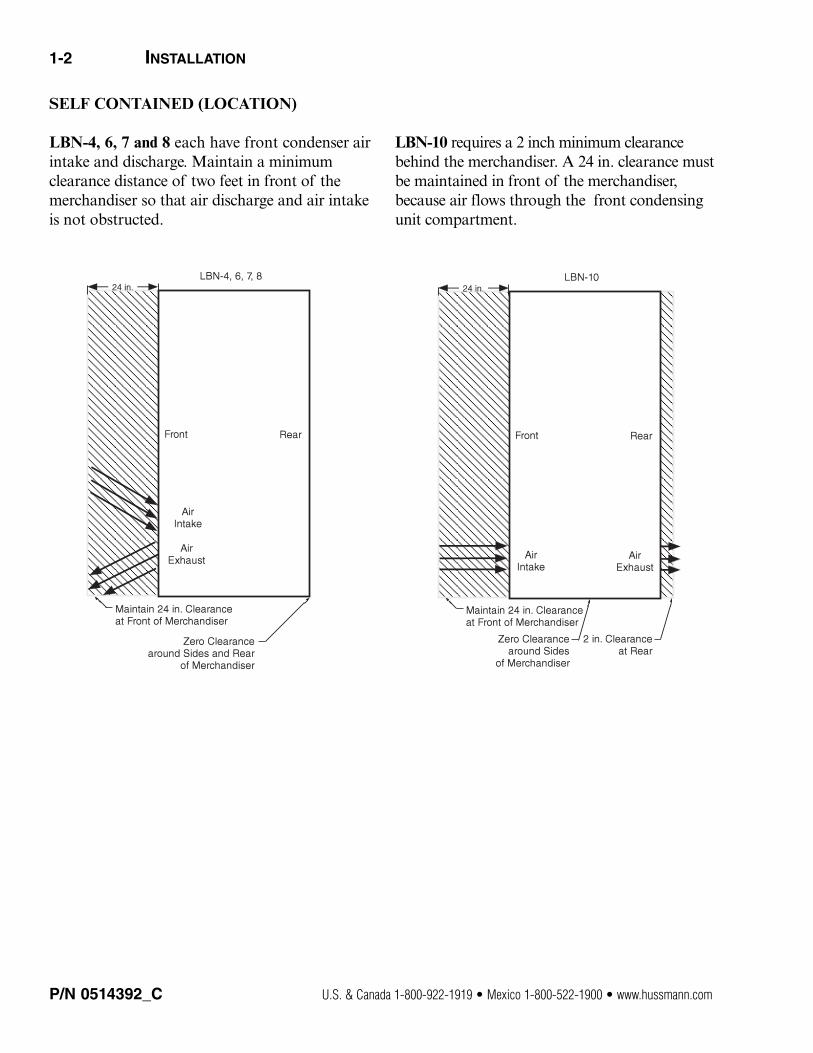
SELF CONTAINED (LOCATION)
LBN-4, 6, 7 and 8 each have front condenser airintake and discharge. Maintain a minimumclearance distance of two feet in front of themerchandiser so that air discharge and air intakeis not obstructed.
LBN-10 requires a 2 inch minimum clearancebehind the merchandiser. A 24 in. clearance mustbe maintained in front of the merchandiser,because air flows through the front condensingunit compartment.
P/N 0514392_C U.S. & Canada 1-800-922-1919 • Mexico 1-800-522-1900 • www.hussmann.com
P/N 0514392_C 1-3
MODEL DESCRIPTION
The LBN series are low temperature, self-containedcabinets designed for pre-packaged ice cream,ice cream novelties, and frozen food at belowfreezing temperatures. Design features includenon-heated glass lids, foamed in place non-CFC insulation, interior mirrors, reflectors,front-air discharge condensing unit, (exceptLBN-10) and a balanced refrigeration systemfor energy-saving performance.
UNLOADING
Unloading from Trailer:Use a Lever Bar (also known as a Mule,Johnson Bar, J-bar, Lever Dolly, or Pry Lever).
Move the merchandiser as close as possible toits permanent location and remove all packaging.Check for damage before discarding packaging.Remove all separately packed accessories suchas kits and shelves.
Improper handling may cause damage to themerchandiser when unloading. To avoid damage:
1. Do not drag the merchandiser out of the trailer. Use a Johnson bar (mule).
2. Use a forklift or dolly to remove the merchandiser from the trailer.
EXTERIOR LOADING
Do NOT walk on top of merchandisers or damage to the merchandisers and serious personal injury could occur.
MERCHANDISERS ARE NOT STRUCTURALLY
DESIGNED TO SUPPORT EXTERNAL LOADING suchas the weight of a person. Do not place heavyobjects on the merchandiser.
SHIPPING SKID
Each merchandiser is shipped on a skid to protect the merchandiser’s base, and to make positioning the case easier.
Do not remove the shipping skid until the merchandiser is near its final location. The skidprovides protection for both the merchandiserand the floor.
Remove the skid by raising one end of the merchandiser approximately 6 inches. Block themerchandiser securely, and remove the two skidbolts from the raised end. Replace the bolts with(provided) leg levelers. Repeat this procedure atopposing end. Once the leg levelers are securedin place, the merchandiser may be slid off theskid and placed in its final location.
DO NOT TILT MERCHANDISER ON ITSSIDE OR END WHEN REMOVING SKID.
Once the skid is removed, the merchandisermust be lifted —NOT PUSHED— to reposition.
Check floor where merchandisers are to be setto see if it is a level area. Determine the highestpart of the floor.
HUSSMANN CORPORATION • BRIDGETON, MO 63044-2483 U.S.A. LBN Horizontal Merchandisers
Do not walk or put heavy objects on case.
Do NOT remove shipping crate until the merchandiser is positioned for installation.
1-4 INSTALLATION
MERCHANDISER LEVELING
BE SURE TO POSITION MERCHANDISERS PROPERLY.Level the merchandiser by all four corners.Merchandiser(s) must be installed level toensure proper operation of the refrigerationsystem, and to ensure proper drainage ofdefrost water. A slight pitch from front to backis desirable. The cabinet back should never behigher than the front.
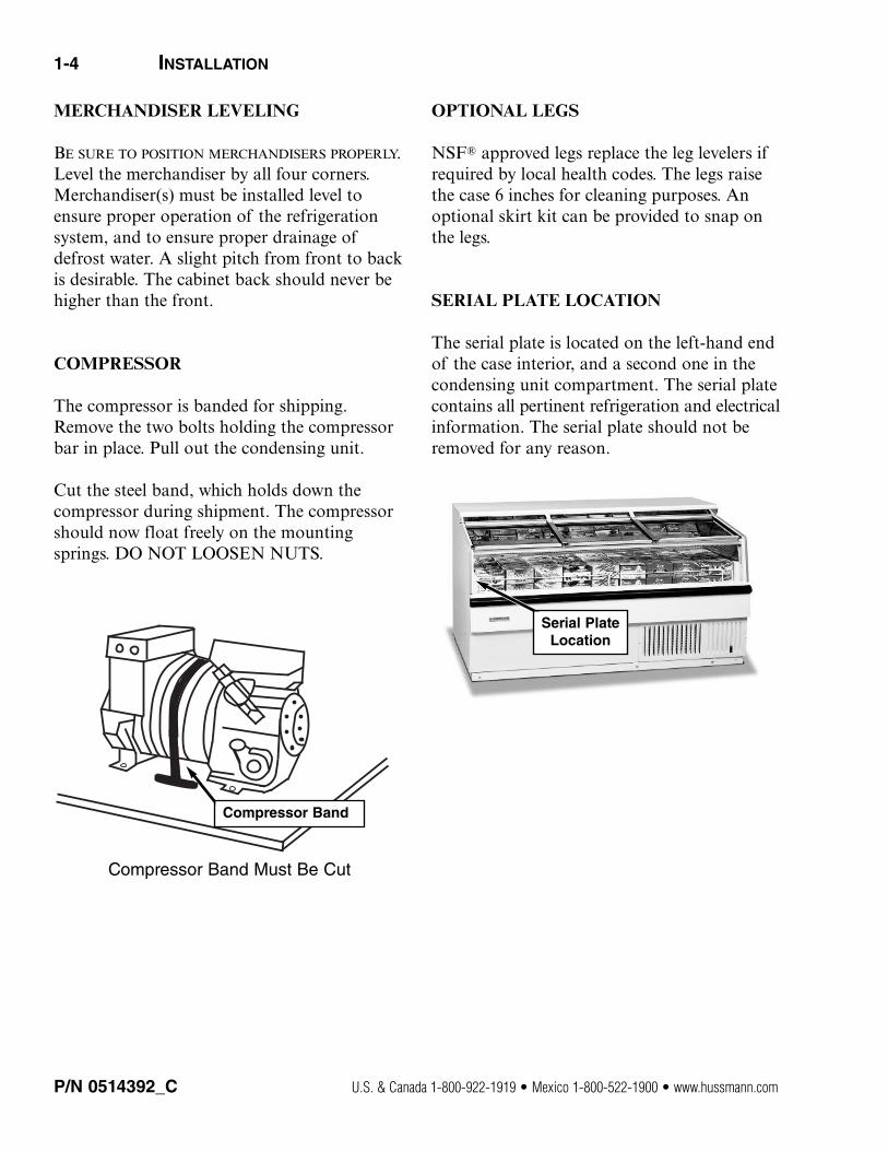
COMPRESSOR
The compressor is banded for shipping.Remove the two bolts holding the compressorbar in place. Pull out the condensing unit.
Cut the steel band, which holds down the compressor during shipment. The compressorshould now float freely on the mountingsprings. DO NOT LOOSEN NUTS.
Compressor Band Must Be Cut
OPTIONAL LEGS
NSF® approved legs replace the leg levelers ifrequired by local health codes. The legs raisethe case 6 inches for cleaning purposes. Anoptional skirt kit can be provided to snap onthe legs.
SERIAL PLATE LOCATION
The serial plate is located on the left-hand endof the case interior, and a second one in thecondensing unit compartment. The serial platecontains all pertinent refrigeration and electricalinformation. The serial plate should not beremoved for any reason.
P/N 0514392_C U.S. & Canada 1-800-922-1919 • Mexico 1-800-522-1900 • www.hussmann.com
Compressor Band
Serial PlateLocation
P/N 0514392_C 1-5
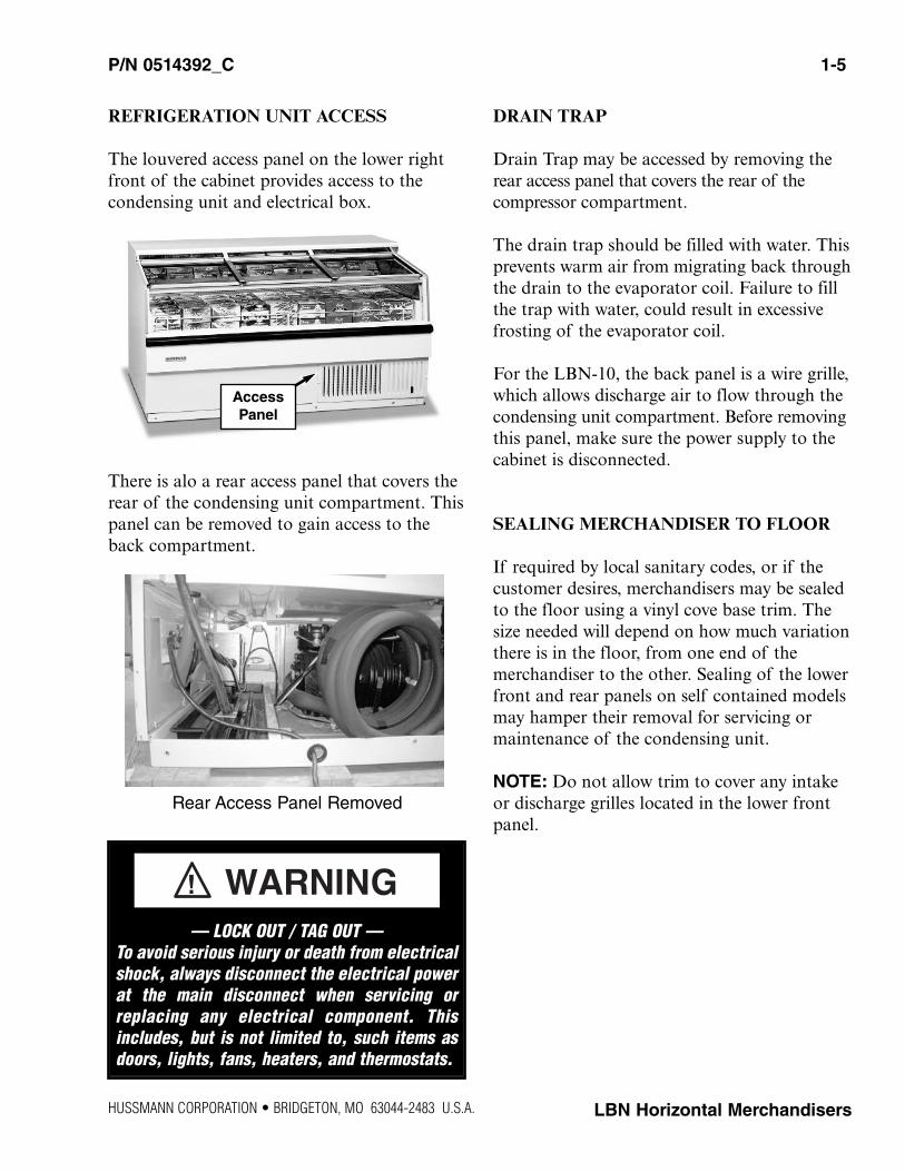
REFRIGERATION UNIT ACCESS
The louvered access panel on the lower rightfront of the cabinet provides access to the condensing unit and electrical box.
There is alo a rear access panel that covers therear of the condensing unit compartment. Thispanel can be removed to gain access to theback compartment.
Rear Access Panel Removed
DRAIN TRAP
Drain Trap may be accessed by removing therear access panel that covers the rear of the compressor compartment.
The drain trap should be filled with water. This prevents warm air from migrating back throughthe drain to the evaporator coil. Failure to fillthe trap with water, could result in excessivefrosting of the evaporator coil.
For the LBN-10, the back panel is a wire grille,which allows discharge air to flow through thecondensing unit compartment. Before removingthis panel, make sure the power supply to thecabinet is disconnected.
SEALING MERCHANDISER TO FLOOR
If required by local sanitary codes, or if thecustomer desires, merchandisers may be sealedto the floor using a vinyl cove base trim. Thesize needed will depend on how much variationthere is in the floor, from one end of the merchandiser to the other. Sealing of the lowerfront and rear panels on self contained modelsmay hamper their removal for servicing ormaintenance of the condensing unit.
NOTE: Do not allow trim to cover any intakeor discharge grilles located in the lower frontpanel.
HUSSMANN CORPORATION • BRIDGETON, MO 63044-2483 U.S.A. LBN Horizontal Merchandisers
AccessPanel
— LOCK OUT / TAG OUT —To avoid serious injury or death from electricalshock, always disconnect the electrical powerat the main disconnect when servicing orreplacing any electrical component. Thisincludes, but is not limited to, such items asdoors, lights, fans, heaters, and thermostats.

1-6 INSTALLATION
NOTES:
P/N 0514392_C U.S. & Canada 1-800-922-1919 • Mexico 1-800-522-1900 • www.hussmann.com

HUSSMANN CORPORATION • BRIDGETON, MO 63044-2483 U.S.A. LBN Horizontal Merchandisers
MERCHANDISER ELECTRICAL DATA
Refer to Appendix A of this manual or themerchandiser’s serial plate for electrical information.
FIELD WIRING
Field wiring must be sized for componentamperes stamped on the serial plate. Actualampere draw may be less than specified.
ELECTRICAL CONNECTIONS
LBN-4, 6, 7 and 8 models have a power cordattached to the unit with a ground prong. Thecord is rated 115V / 15 Amp. The LBN-7 and 8also require a circuit breaker or a time delayfuse rated at 15 Amps for the circuit being runto them. LBN-10 requires conduit connectionsof both 115V and 208V with an amperage rat-ing of 15 amps for each circuit. Marked leadsare provided for these connections in the field.If wiring the LBN-10 to a “3-wire” system ispreferred, a 20 Amp 208 - 230V circuit needsto be provided.
All of these models are 60 hz, 1 ph.Connecting this unit to any electrical supplyother than specified on the serial plate will voidthe warranty and may result in serious damageto the unit. The cabinet should be suppliedwith its OWN service.
POWER SWITCH
The power switch is located at the electricalbox that is behind the front, louvered accesspanel. A slot in one of the louvers allowsaccess to the switch. The switch will shut off allpower to the cabinet on the LBN-4, 6, 7 and 8.The power switch will shut off the 208-230Vcircuit on the LBN-10.
ELECTRICAL BOX
The electrical box contains the defrost timeclock, terminal boards and power switch. Thebox is capable of sliding out for servicing convenience. Access is gained by removing thecover on the side of the box above. See the diagram below concerning a “3-wire” system.
ELECTRICAL / REFRIGERATION
ALWAYS CHECK THE SERIAL PLATE FOR COMPONENT AMPERES
Merchandiser must be grounded.Do not remove the power supply cord ground.
PowerSwitch
P/N 0514392_C 2-1
2-2 ELECTRICAL / REFRIGERATION
P/N 0514392_C U.S. & Canada 1-800-922-1919 • Mexico 1-800-522-1900 • www.hussmann.com
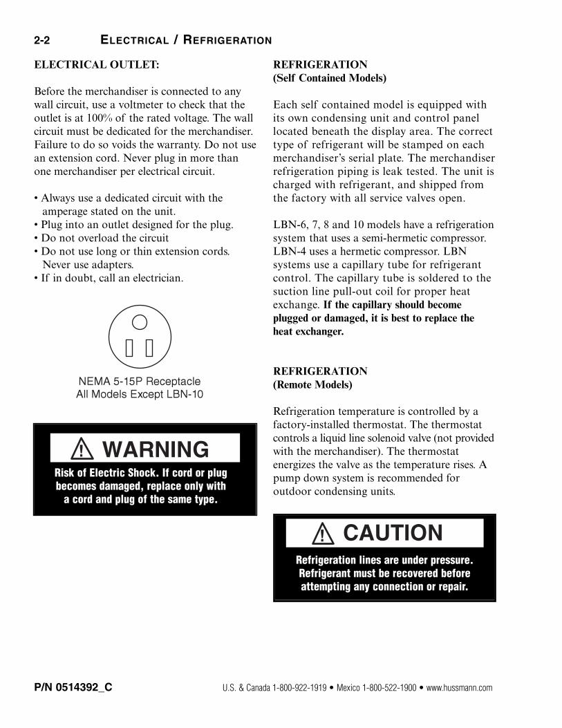
ELECTRICAL OUTLET:
Before the merchandiser is connected to anywall circuit, use a voltmeter to check that theoutlet is at 100% of the rated voltage. The wallcircuit must be dedicated for the merchandiser.Failure to do so voids the warranty. Do not usean extension cord. Never plug in more thanone merchandiser per electrical circuit.
• Always use a dedicated circuit with the amperage stated on the unit. • Plug into an outlet designed for the plug.• Do not overload the circuit• Do not use long or thin extension cords.Never use adapters.• If in doubt, call an electrician.
REFRIGERATION(Self Contained Models)
Each self contained model is equipped withits own condensing unit and control panellocated beneath the display area. The correcttype of refrigerant will be stamped on eachmerchandiser’s serial plate. The merchandiserrefrigeration piping is leak tested. The unit ischarged with refrigerant, and shipped fromthe factory with all service valves open.
LBN-6, 7, 8 and 10 models have a refrigerationsystem that uses a semi-hermetic compressor.LBN-4 uses a hermetic compressor. LBNsystems use a capillary tube for refrigerantcontrol. The capillary tube is soldered to thesuction line pull-out coil for proper heatexchange. If the capillary should becomeplugged or damaged, it is best to replace theheat exchanger.
REFRIGERATION(Remote Models)
Refrigeration temperature is controlled by afactory-installed thermostat. The thermostatcontrols a liquid line solenoid valve (not providedwith the merchandiser). The thermostat energizes the valve as the temperature rises. Apump down system is recommended for outdoor condensing units.
Refrigeration lines are under pressure.Refrigerant must be recovered beforeattempting any connection or repair.
Risk of Electric Shock. If cord or plug becomes damaged, replace only with
a cord and plug of the same type.
P/N 0514392_C 2-3
LINE SIZING(Remote Models)
Refrigerant line connections are made at theright end of merchandiser (facing front)beneath the refrigerated display area. Therefrigerant line connection size is 3/8 in. Thesuction line is 5/8 in. Refrigerant lines should besized as shown on the refrigeration legend thatis furnished for the store or according toASHRAE guidelines.
WATER OUTLET AND WATER SEAL
The condensate water outlet is located on theright side of the merchandiser. The outlet has afactory installed, external water seal.
For self contained models like, this water sealdrains into the condensate evaporator panlocated beneath the merchandiser. Ensure thedrain hose is properly trapped, and the drainarea is not clogged.
For remote models connect the drain hose to a floor drain. Ensure that the drain hose is properly trapped.
NOTE: All lower base panels must be in placewhen the refrigerator is operating. If not, air-flow from the condenser will be directed overthe evaporator pan and defrost water in thepan may overflow.
ELECTROMECHANICAL CONTROLS
These merchandisers require defrost cyclesfor proper operation. Refer to the technicaldata Section for application data. Defrostsare time-initiated and temperature terminated.The defrost timer duration is factory set.
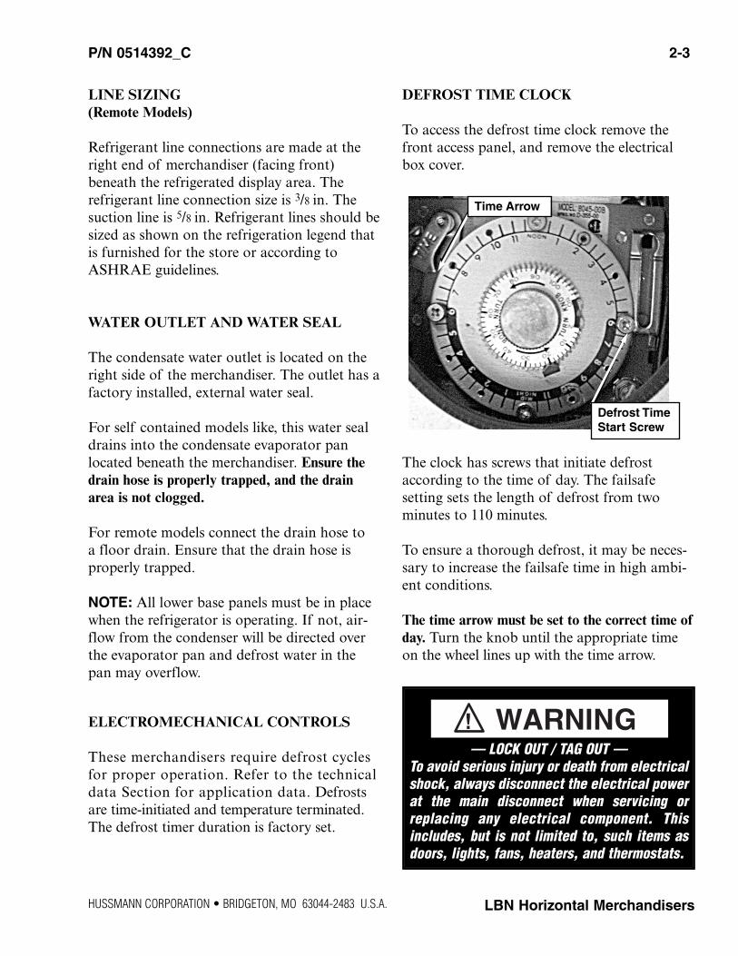
DEFROST TIME CLOCK
To access the defrost time clock remove thefront access panel, and remove the electricalbox cover.
The clock has screws that initiate defrostaccording to the time of day. The failsafesetting sets the length of defrost from two minutes to 110 minutes.
To ensure a thorough defrost, it may be neces-sary to increase the failsafe time in high ambi-ent conditions.
The time arrow must be set to the correct time ofday. Turn the knob until the appropriate timeon the wheel lines up with the time arrow.
HUSSMANN CORPORATION • BRIDGETON, MO 63044-2483 U.S.A. LBN Horizontal Merchandisers
Time Arrow
Defrost TimeStart Screw
— LOCK OUT / TAG OUT —To avoid serious injury or death from electricalshock, always disconnect the electrical powerat the main disconnect when servicing orreplacing any electrical component. Thisincludes, but is not limited to, such items asdoors, lights, fans, heaters, and thermostats.
2-4 ELECTRICAL / REFRIGERATION
SETTING DEFROST TIME CLOCK
The timer is factory pre-set for one defrostcycle per 48 hours for LBN-4, 6, 7 and 8. TheLBN-10 timer is factory pre-set for one defrostcycle per 24 hours starting at 12:00 a.m. with a40-minute failsafe.
The timer must be adjusted to the proper timeof day when the cabinet is started. The timer isadjusted by turning the knurled adjustmentknob in the center of the dial face counter-clockwise until the time indicator correspondswith the correct time of day.
The defrost pins should be checked for tightness.The timer will require re-adjusting after apower failure or the cabinet supply is turnedoff for extended periods of time. If an addi-tional defrost is required due to ambient orcabinet usage conditions, do not start a defrostduring the middle of the day. Put any additionaldefrosts during the night or at a time when thecabinet has the lowest usage.
Defrost is time initiated and temperature terminated.
The timer has a failsafe if the thermostat fails.The failsafe is set at 40 minutes and will allowdefrost to terminate on time.
Allow merchandiser 24 hours to operate before loading product. Always load with pre-frozenproduct.
CRANKCASE PRESSURE REGULATOR
The LBN series employ a crankcase pressureregulator in the suction line and is consideredpart of the heat exchanger. The CPR is set to10 psig. The purpose of the value is to main-tain a low suction pressure on start-up so thatthe compressor will start properly.
On start-up, the valve will hold the suctionpressure at the desired setting until the suctionpressure has dropped below the setting, thenthe valve will open.
If it becomes necessary to check or reset thesetting, the cabinet must be warm such as aftera defrost cycle or from an initial warm cabinetcondition.
Put a suction compound gauge on the com-pressor suction valve. Start the compressor. Ifthe pressure needs to be reduced turn theadjustment screw clockwise to raise the pres-sure.
Do not set the valve based on the serial plateamperage rating, because the pressure settingwill be too high, and the compressor will notstart properly.
P/N 0514392_C U.S. & Canada 1-800-922-1919 • Mexico 1-800-522-1900 • www.hussmann.com
Product will be degraded and may spoil ifallowed to sit in a non-refrigerated area.
— LOCK OUT / TAG OUT —To avoid serious injury or death from electricalshock, always disconnect the electrical powerat the main disconnect when servicing orreplacing any electrical component. Thisincludes, but is not limited to, such items asdoors, lights, fans, heaters, and thermostats.
START UP
Follow the electromechanical controls start upprocedures as detailed in Section 2 of thismanual.
Each self contained merchandiser has its ownevaporator coil. LBN models have capillarytubes.
a. Check the interior cabinet thoroughly for loose nuts, bolts and electrical connections.
b. Inspect the refrigeration lines for visible damage or chafing.
c. Replace electrical box cover and access panel.
d. Turn on the electrical power, power switch and start the merchandiser. The merchandiser must pull down in temperature. Allowmerchandiser 24 hours to operate before loading product.
1. The T-stat controller controls refrigerationtemperature. This is factory installed in thecontrol panel.
Defrosts are time initiated and temperature terminated for self contained and remote. Thedefrost setting is factory set as shown above.
HUSSMANN CORPORATION • BRIDGETON, MO 63044-2483 U.S.A. LBN Horizontal Merchandisers
P/N 0514392_C 3-1
START UP / OPERATION
COMPRESSOR
Cut the steel band, which holds downthe compressor during shipment. Thecompressor should now float freely onthe mounting springs. DO NOTLOOSEN NUTS.
NOTE: Failure to cut compressor shipment band may result in excessivenoise or system damage, which is notcovered by warranty.
INSTALLER

LOAD LIMITS
Each merchandiser has a load limit decal. Shelflife of perishables will be short if load limit is violated.
AT NO TIME SHOULD MERCHANDISERS BE
STOCKED BEYOND THE LOAD LIMITS INDICATED.
DO NOT BLOCK AIR GRILLE.
STOCKING
Product should NOT be placed inside the merchandisers until merchandisers are at proper operating temperature.
Allow merchandiser 24 hours to operate beforeloading product.
Proper rotation of product during stocking is necessary to prevent product loss. Always bringthe oldest product to the front and set thenewest to the back.
AIR DISCHARGE FLUES MUST REMAIN OPEN AND
FREE OF OBSTRUCTION AT ALL TIMES to provideproper refrigeration and air curtain perfor-mance. Do not allow product, packages, signs,etc. to block the grille. Do not use non-approved shelving, baskets, display racks, orany accessory that could hamper air curtainperformance.
Do not allow product to be placed outside ofthe designated load limits in the illustration atright.
THERMOMETER
The cabinet has a thermometer located on theleft-hand end of the nose screen that is justbelow the upper mirror reflector and light fix-ture. The thermometer is a “pencil” type andreads from -40º F to 80º F on 2º increments.To replace, remove the two screws and installthe replacement.
3-2 START UP / OPERATION
P/N 0514392_C U.S. & Canada 1-800-922-1919 • Mexico 1-800-522-1900 • www.hussmann.com
Product will be degraded and may spoil ifallowed to sit in a non-refrigerated area.
Do not load merchandiser with product above load limit.
P/N 0514392_C 4-1
HUSSMANN CORPORATION • BRIDGETON, MO 63044-2483 U.S.A. LBN Horizontal Merchandisers
CARE AND CLEANING
Long life and satisfactory performance of anyequipment is dependent upon the care itreceives. To ensure long life, proper sanitationand minimum maintenance costs, these merchandisers should be thoroughly cleaned,all debris removed and the interiors washeddown, weekly.
Exterior SurfacesThe exterior surfaces must be cleaned with amild detergent and warm water to protect andmaintain their attractive finish. NEVER USE
ABRASIVE CLEANSERS OR SCOURING PADS.
Interior SurfacesThe interior surfaces may be cleaned with mostdomestic detergents, ammonia based cleanersand sanitizing solutions with no harm to thesurface. Self contained models empty into alimited capacity evaporation pan, which willoverflow if excess water is used in cleaning.
Do NOT Use:
•Abrasive cleansers and scouring pads, as thesewill mar the finish.
•Coarse paper towels on coated glass.
•Ammonia-based cleaners on acrylic parts.
•Solvent, oil or acidic based cleaners on any interior surfaces.
•Do not use high pressure water hoses.
Do:
•Disconnect electrical power before cleaning.
•Remove the product and all loose debris toavoid clogging the waste outlet.
•Store product in a refrigerated area such as a cooler. Remove only as much product as canbe taken to the cooler in a timely manner.
•Thoroughly clean all surfaces with soap andhot water. DO NOT USE STEAM OR HIGH WATER
PRESSURE HOSES TO WASH THE INTERIOR. THESE
WILL DESTROY THE MERCHANDISERS’ SEALINGCAUSING LEAKS AND POOR PERFORMANCE.
•Lift hinged fan plenum for cleaning. Hookchain in rear panel to secure plenum duringcleaning. BE SURE TO REPOSITION THE FAN
PLENUM AFTER CLEANING MERCHANDISER.
•Take care to minimize direct contact betweenfan motors and cleaning or rinse water.
•Do NOT flood merchandiser with water.NEVER INTRODUCE WATER FASTER THAN THE
WASTE OUTLET CAN REMOVE IT.
SELF CONTAINED MODELS EMPTY INTO AN
EVAPORATION PAN THAT WILL OVERFLOW IF TOO
MUCH WATER IS INTRODUCED DURING CLEANING.
•Allow merchandisers to dry before resumingoperation.
•After cleaning is completed, turn on power tothe merchandiser.
MAINTENANCE
Product will be degraded and may spoil if allowed to sit in a non-refrigerated area.
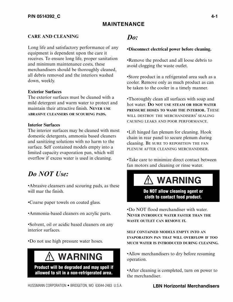
Do NOT allow cleaning agent or cloth to contact food product.
4-2 MAINTENANCE
CLEANING DISCHARGE AIR GRILLE
Discharge air air grilles should be cleanedevery six months. Dirty air grilles will causemerchandisers to perform poorly. The airgrilles may be cleaned with a vacuum cleaner.Soap and water may be used if all water isremoved from the air grilles cells before replacing.Be careful not to damage the air grilles.
CLEANING SOLAR THERMOMETER
LBN models have solar thermometers. Thethermometer is located at the top, front centerof the merchandiser’s cabinet interior.
To clean the thermometer:1. Remove the two screws securing the ther-
mometer to its mounting bracket. Removethe sensing element from the clip
2. Use non-abrasive cleaning materials and amild detergent to clean thermometer.
3. Be sure to wipe the element clean of anyresidues.
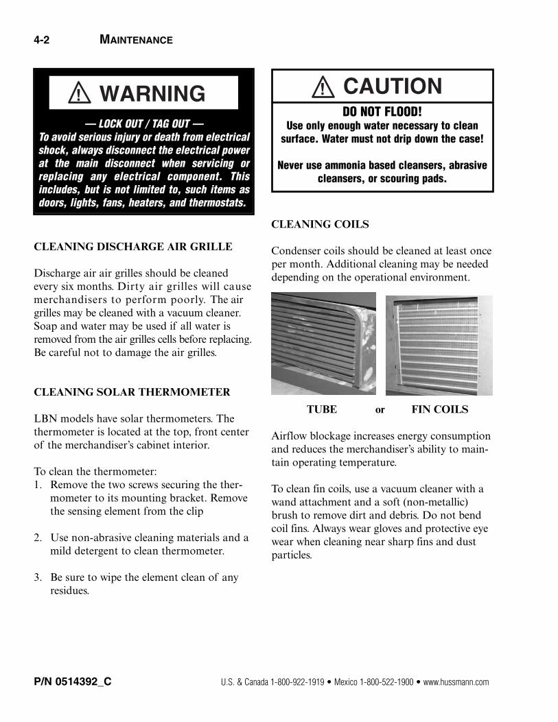
CLEANING COILS
Condenser coils should be cleaned at least onceper month. Additional cleaning may be neededdepending on the operational environment.
TUBE or FIN COILS
Airflow blockage increases energy consumptionand reduces the merchandiser’s ability to main-tain operating temperature.
To clean fin coils, use a vacuum cleaner with awand attachment and a soft (non-metallic)brush to remove dirt and debris. Do not bendcoil fins. Always wear gloves and protective eyewear when cleaning near sharp fins and dustparticles.
P/N 0514392_C U.S. & Canada 1-800-922-1919 • Mexico 1-800-522-1900 • www.hussmann.com
— LOCK OUT / TAG OUT —To avoid serious injury or death from electricalshock, always disconnect the electrical powerat the main disconnect when servicing orreplacing any electrical component. Thisincludes, but is not limited to, such items asdoors, lights, fans, heaters, and thermostats.
DO NOT FLOOD!Use only enough water necessary to clean
surface. Water must not drip down the case!
Never use ammonia based cleansers, abrasivecleansers, or scouring pads.

The condenser is of bare-tube construction onthe LBN-4, 6, 7 and 8 to reduce the amount ofrequired maintenance required, and fin-and-tube construction on the LBN-10.
To ease in the cleaning of the bare-tube con-denser, the top of the condenser shroud isremovable. Slit the upper corners of the gasketon the front of the condenser. Remove thescrews holding the shroud top into the shroudends, and remove the top to gain full access tothe condenser.
The glass lids are made of tempered, non-heatedglass. The lids slide up to open and can belocked open for product loading. The lids arenot self-closing. The lids will close easily byhand and with the assistance of gravity. Thereis a nylon glide on the edge of the glass toassist in closing. The lid tracks must be cleanedperiodically to allow the lids to close freely.
Manually defrost cabinet as usage dictates. TheLBN series are gravity-cooled cabinets. Thesidewalls have refrigeration tubing in them tocool the lower portion of the interior and thereis an upper evaporator that drops cold airdown onto the product. The upper coil isequipped with defrost heaters that defrost thecoil. The side walls of the cabinet will build upfrost and ice on them over time and do need tobe manually defrosted as usage and build updemands.
CLEANING EVAPORATION PAN
The condensate water outlet for self containedmodels empties into a limited capacity evapo-ration pan.
Debris or dirt accumulation inside the condensateevaporation pan will reduce the pan’s evaporationcapacity.
Remove accumulated debris from the evaporationpan. Water introduced during cleaning willcause the evaporation pan to overflow.
P/N 0514392_C 4-3
HUSSMANN CORPORATION • BRIDGETON, MO 63044-2483 U.S.A. LBN Horizontal Merchandisers
Always Wear gloves and protective eye wearwhen servicing. Turn off evaporation panheater, and allow pan to cool.
SHUT FANS OFF DURING CLEANING PROCESS.
4-4 MAINTENANCE
CLEANING STAINLESS STEEL SURFACES
Use non-abrasive cleaning materials, andalways polish with grain of the steel. Use warmwater or add a mild detergent to the water andapply with a cloth. Always wipe rails dry afterwetting.
Use alkaline chlorinated or non-chlorine containing cleaners such as window cleanersand mild detergents. Do not use cleaners containing salts as this may cause pitting andrusting of the stainless steel finish. Do not usebleach.
REMOVING SCRATCHES FROM BUMPER
Most scratches and dings can be removedusing the following procedure.
1. Use steel wool to smooth out the surfacearea of the bumper.
2. Clean area.
3. Apply vinyl or car wax and polish surfacefor a smooth glossy finish.
P/N 0514392_C U.S. & Canada 1-800-922-1919 • Mexico 1-800-522-1900 • www.hussmann.com
PRECAUTION CLEANING PRECAUTIONS
When Cleaning:
UNIT WITH AN EVAPORATION PAN
THAT HAS OIL BASE (these will dissolve the butyl sealants) or an AMMONIA BASE (this will corrode the copper components of the merchandiser)
(these will mar the finish)
Do NOT use HOT water on Cold glass Surfaces.This can cause the glass to shatter and couldresult in personal injury. Allow glass fronts, to
warm before applying hot water.

P/N 0514392_C 5-1
HUSSMANN CORPORATION • BRIDGETON, MO 63044-2483 U.S.A. LBN Horizontal Merchandisers
DEFROST THERMOSTAT REPLACEMENT
The defrost thermostat is located on its mountingplate, at the right end of the evaporator coilattached to the air scoop. The air scoop is aright angle piece of metal running in front ofthe evaporator behind the nose screen. Thethermostat is a bi-metal thermostat that is tiedin series with the defrost time clock solenoid toend defrost when the temperature has been satisfied (85º F).To Replace Defrost Thermostat:
1. If it is determined that the defrost thermostatneeds to be replaced, disconnect electricalpower to the merchandiser.
2. Remove the nose screen from in front ofthe evaporator.
3. Remove the stainless steel mirror reflectorover the light fixture.
4. Refer to the wiring diagram for thermostatwiring terminations and disconnect.
5. Remove the air scoop located in front ofthe evaporator coil and the defrost thermo-stat mounting plate attached to it. Removethe thermostat, and disconnect wires.
6. Reverse this procedure to reinstall thenew thermostat.
DEFROST HEATER REPLACEMENT
The cabinet is equipped with two defrostheaters, which are wired in parallel, except forthe LBN-4, 6, 7 and 8, 220V, which are wiredin series. Wiring them this way allows for lowerwattage which increases the life of the heater.The drain pan does not have to be removed toreplace the heaters.
The heaters are equipped with plug-in connec-tions that plug into the underside of the lightfixture. Disconnect electrical power supply.
Remove the stainless steel reflector. Removethe nose screen in front of the evaporator area.
The heaters are held up against the evaporatorby spring clips.
Press heaters down and pull up on the frontedge of the heater clips. The heaters can befulled forward.
When replacing be sure the back pass of therear defrost heater goes into the retaining clipat the back of the drain pan. This is necessaryto prevent ice build up in the drain pan.
SERVICE
— LOCK OUT / TAG OUT —To avoid serious injury or death from electricalshock, always disconnect the electrical powerat the main disconnect when servicing orreplacing any electrical component. Thisincludes, but is not limited to, such items asdoors, lights, fans, heaters, and thermostats.
5-2 SERVICE
P/N 0514392_C U.S. & Canada 1-800-922-1919 • Mexico 1-800-522-1900 • www.hussmann.com
REPLACEMENTS OF CONDENSATEHEATERS
There are condensate heaters behind the stain-less steel end panels, around the front glass,and behind the nose screen. These heaters arethermostatically controlled in case the cabinetmalfunctions and thermostat senses above 101º Fat which time the heaters will shut off.
REPLACEMENT OF END PANELHEATERS
The end panel heaters are located behind theend panel stainless steel reflectors. They can beremoved by removing the screws on the bottomedge of the panel and pulling down on the bottom edge. The heater is on adhesive foil onthe backside of the panel.
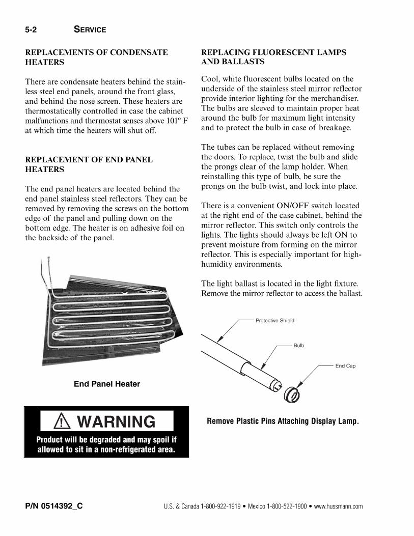
End Panel Heater
REPLACING FLUORESCENT LAMPSAND BALLASTS
Cool, white fluorescent bulbs located on theunderside of the stainless steel mirror reflectorprovide interior lighting for the merchandiser.The bulbs are sleeved to maintain proper heataround the bulb for maximum light intensityand to protect the bulb in case of breakage.
The tubes can be replaced without removingthe doors. To replace, twist the bulb and slidethe prongs clear of the lamp holder. Whenreinstalling this type of bulb, be sure theprongs on the bulb twist, and lock into place.
There is a convenient ON/OFF switch locatedat the right end of the case cabinet, behind themirror reflector. This switch only controls thelights. The lights should always be left ON toprevent moisture from forming on the mirrorreflector. This is especially important for high-humidity environments.
The light ballast is located in the light fixture.Remove the mirror reflector to access the ballast.
Remove Plastic Pins Attaching Display Lamp.
Product will be degraded and may spoil ifallowed to sit in a non-refrigerated area.
P/N 0514392_C 5-3
HUSSMANN CORPORATION • BRIDGETON, MO 63044-2483 U.S.A. LBN Horizontal Merchandisers
FRONT GLASS HEATER REPLACEMENT
The front glass heater is built as part of theglass assembly. The purpose of the heater is tokeep the aluminum trim surrounding the glassfree of condensation. If the cabinet is locatedin a high humidity environment, the center ofthe glass may have a trace of condensation across it.
To replace the glass assembly:
1. Disconnect power to the cabinet. Remove thecabinet top by removing the screws that hold itinto the back of the cabinet, and on each end.
2. Lift the top off the cabinet.
3. Remove the lids.
4. Remove the screws holding the backs ofthe lid tracks to the galvanized sub-top andthe screws holding the center tracks to thealuminum rail on top of the front glass.
5. Remove the plastic arm trim breakers inthe end aluminum trim pieces to expose thescrews in them. Remove screws and removeend trim.
6. Remove the trim from the top of the frontglass.
7. Pull the front glass up and out exposingthe wires at the right hand end of the glassand disconnect.
8. Replace the glass assembly.
9. Reverse procedure to reassemble.
NOSE HEATER REPLACEMENT
The nose heater is located behind the nosescreen that is in front of the evaporator.Remove the nose screen replace heater.
CONDENSATE HEATER LIMIT THERMOSTAT
The condensate heater limit thermostat is asafety feature that will shut off the condensateheaters just discussed when the thermostatsenses 101º F.
The thermostat is located on the defrost thermostat mounting bracket, which is on theair scoop behind the nose screen in front of theevaporator.
P/N 0514392_C U.S. & Canada 1-800-922-1919 • Mexico 1-800-522-1900 • www.hussmann.com
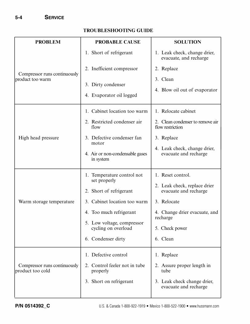
TROUBLESHOOTING GUIDE
5-4 SERVICE
PROBLEM
Compressor runs continuouslyproduct too warm
High head pressure
Warm storage temperature
Compressor runs continuouslyproduct too cold
PROBABLE CAUSE
1. Short of refrigerant
2. Inefficient compressor
3. Dirty condenser
4. Evaporator oil logged
1. Cabinet location too warm
2. Restricted condenser air flow
3. Defective condenser fan motor
4. Air or non-condensable gases in system
1. Temperature control not set properly
2. Short of refrigerant
3. Cabinet location too warm
4. Too much refrigerant
5. Low voltage, compressor cycling on overload
6. Condenser dirty
1. Defective control
2. Control feeler not in tube properly
3. Short on refrigerant
SOLUTION
1. Leak check, change drier, evacuate, and recharge
2. Replace
3. Clean
4. Blow oil out of evaporator
1. Relocate cabinet
2. Clean condenser to remove air flow restriction
3. Replace
4. Leak check, change drier, evacuate and recharge
1. Reset control.
2. Leak check, replace drier evacuate and recharge
3. Relocate
4. Change drier evacuate, and recharge
5. Check power
6. Clean
1. Replace
2. Assure proper length in tube
3. Leak check change drier, evacuate and recharge

HUSSMANN CORPORATION • BRIDGETON, MO 63044-2483 U.S.A. LBN Horizontal Merchandisers
P/N 0515275_C 5-5
PROBLEM
Compressor runs continuouslyproduct too cold
Compressor will not start nonoise
Compressor will not start cuts out on overload
Low suction pressureLow head pressure
PROBABLE CAUSE
1. Defective control
2. Control feeler not in tube properly
3. Short on refrigerant
1. Blown fuse or breaker
2. Defective or broken wiring
3. Defective overload
4. Defective temperature control
5. Power disconnected
1. Low voltage
2. Defective compressor
3. Defective relay
4. Restriction or moisture
5. Inadequate air condenser
6. Defective condenser fan motor
7. CRO not set properly
1. CPR not set properly
SOLUTION
1. Replace
2. Assure proper length in tube
3. Leak check change drier, evacuate and recharge
1. Replace fuse or reset breaker
2. Repair or replace
3. Replace
4. Replace
5. Check service cords orwiring connections
1. Contact electrician
2. Replace
3. Replace
4. Leak check, replace drier,evacuate and recharge
5. Clean condenser
6. Replace
7. Reset to 10 psi.
1. Reset to 10 psi.
P/N 0514392_C U.S. & Canada 1-800-922-1919 • Mexico 1-800-522-1900 • www.hussmann.com
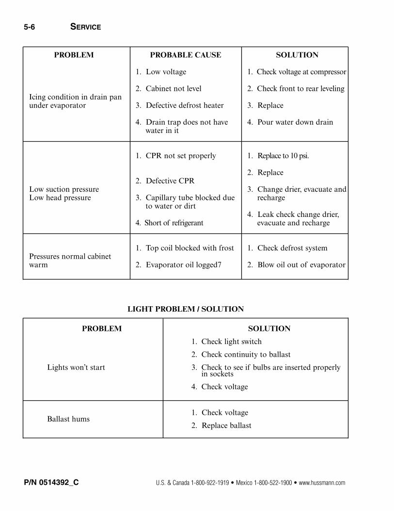
PROBLEM
Icing condition in drain pan under evaporator
Low suction pressureLow head pressure
Pressures normal cabinet warm
PROBABLE CAUSE
1. Low voltage
2. Cabinet not level
3. Defective defrost heater
4. Drain trap does not have water in it
1. CPR not set properly
2. Defective CPR
3. Capillary tube blocked dueto water or dirt
4. Short of refrigerant
1. Top coil blocked with frost
2. Evaporator oil logged7
SOLUTION
1. Check voltage at compressor
2. Check front to rear leveling
3. Replace
4. Pour water down drain
1. Replace to 10 psi.
2. Replace
3. Change drier, evacuate andrecharge
4. Leak check change drier, evacuate and recharge
1. Check defrost system
2. Blow oil out of evaporator
PROBLEM
Lights won’t start
Ballast hums
SOLUTION
1. Check light switch
2. Check continuity to ballast
3. Check to see if bulbs are inserted properly in sockets
4. Check voltage
1. Check voltage
2. Replace ballast
LIGHT PROBLEM / SOLUTION
5-6 SERVICE

HUSSMANN CORPORATION • BRIDGETON, MO 63044-2483 U.S.A. LBN Horizontal Merchandisers
LBN ACCESSORIES AND OPTIONS
The following is a description of the variousaccessories available for the LBN:
Bag Rack — A big rack can be provided tostore various size checkout bags. The rackattaches to the back of the cabinet.
Caster Kit — If the cabinet needs to be movedquite often or for additional health code regulations, the caster kit raises the cabinetapproximately 4 1/2 inches. The wheel of thecaster is 3 inches.
Counter Top — The metal countertop is stan-dard, and a 16 in. and 20 in. wooden counter-top can be provided. The 16 in. wooden coun-tertop mounts flush with the back of the cabi-net.
Dial Thermometer — The cabinet can be pro-vided with a two-inch dial thermometer, ratherthan the standard pencil type thermometer.THIS MUST BE FACTORY INSTALLED. It is locatedin the left end of the upper stainless steelreflector above the light fixture.
Lid Lock Kit — For product security, a lid lockkit cab be provided. Each kit secures two lids.
Novelty Basket — For the storage and displayof novelty ice cream items, the novelty basketis ideal. The basket is epoxy-coated white, andit is 10 in. x 12 in. x 6 1/2 inches high. Basketdividers are also available.
Product Shelf Kit — The interior of the LBNseries a raised step over the condensing unitcompartment. The product shelf kit is a falsebottom of the cabinet level with the raisedstep.
Stainless Steel Top — Like the countertops, thestainless steel top replaces the standard metalcountertop for those who need a highlydurable working surface.
Superstructure with Lighted Canopy — The cabinet can be provided with a superstructure,which has two shelves, and a lighted canopy thatattaches to the back of the cabinet. The super-structure allows for the storage of dry goodswithout the need for additional floor space.
Superstructure with Lighted Canopy — Thesuperstructure can also be provided withoutthe lighted canopy. It is still supplied with twoshelves.
PROBLEM
Lights flicker
SOLUTION
1. Allow lamps to warm up
2. Check lamp sleeves for cracks
3. Check sockets for moisture and proper contact
4. Bulb replacement may be necessary
5. Check voltage
6. New bulbs tend to flicker until used
P/N 0515275_C 5-7

P/N 0514392_C U.S. & Canada 1-800-922-1919 • Mexico 1-800-522-1900 • www.hussmann.com
COMPRESSOR REPLACEMENT PROCEDURE
Replacement compressors will not be shippedfrom the Hussmann factory. They may beobtained from your nearest Copeland wholesaler.
Your wholesaler will replace, free of charge, anycompressor found to be defective within 12months of installation, not to exceed 20 monthsfrom the date of manufacture as determined bythe compressor serial number on the compressorserial plate.
For any defective compressor beyond the 12month or 20 month time period, a salvage valuecredit will be given to partially offset the invoicefor replacement.
After March 16, 1991 when all cases have the five-year warranty as standard, the following proce-dure applies:
FORWARD TO YOUR NEAREST HUSSMANN
DISTRIBUTOR:
1. The cabinet model and serial number.
2. A copy of the wholesaler’s invoice, along with acopy of the salvage value credit.
INTERNAL LEAK WARRANTY POLICY
The LBN series are warranted from the date offactory shipment for five years for an internalleak. An internal leak not only includes thecold-wall tubing but the upper evaporator aswell on these models.
If it is felt that there is an internal leak in thecabinet, care should be taken to actually determine that there is a leak.
To do this properly, the cabinet’s evaporatorsection must be isolated from the condensersection.
Unbraze the tubes going into the back of thecabinet at the end of the heat exchanger.
Pinch or cap the larger tube and braze shut.
Add a schrader valve to the smaller tube.
Attach the high side gauge of a compoundgauge to the valve and pressurize the cabinetwith nitrogen or otherwise suitable gas.
There should be at least 300 psi on the system.
Mark the pressure on the gauge and leave it,returning 24 hours later.
Note the pressure. If it has fallen more than150-200 psi then the system may have an internalleak.
If it only drops a small amount this does notmean that you have an internal leak, but thatthe gas in the cabinet is cooler and has reducedits pressure because of this.
If the cabinet has an internal leak contact thenearest Hussmann distributor or the factory toreceive authorization to return the cabinet tothe factory.
NO MERCHANDISER WILL BE ACCEPTED AT THE
FACTORY WITHOUT A LETTER OF AUTHORIZATION
FOR RETURN.
5-8 SERVICE
HUSSMANN CORPORATION • BRIDGETON, MO 63044-2483 U.S.A. LBN Horizontal Merchandisers
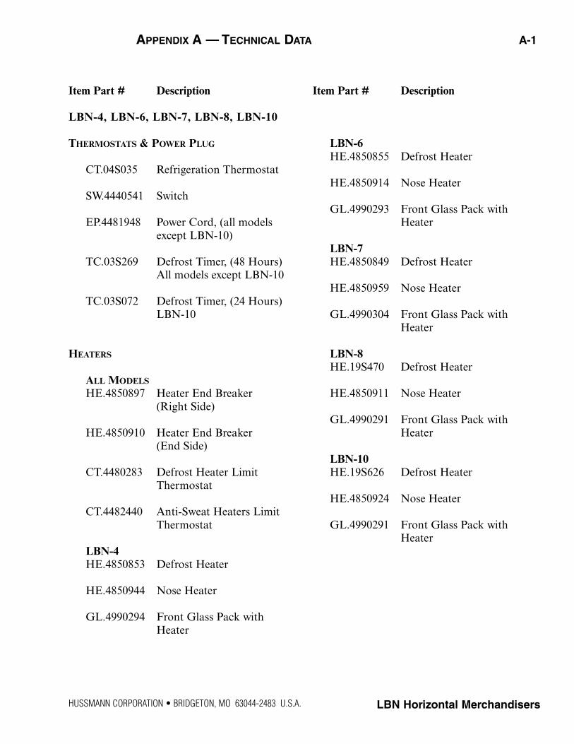
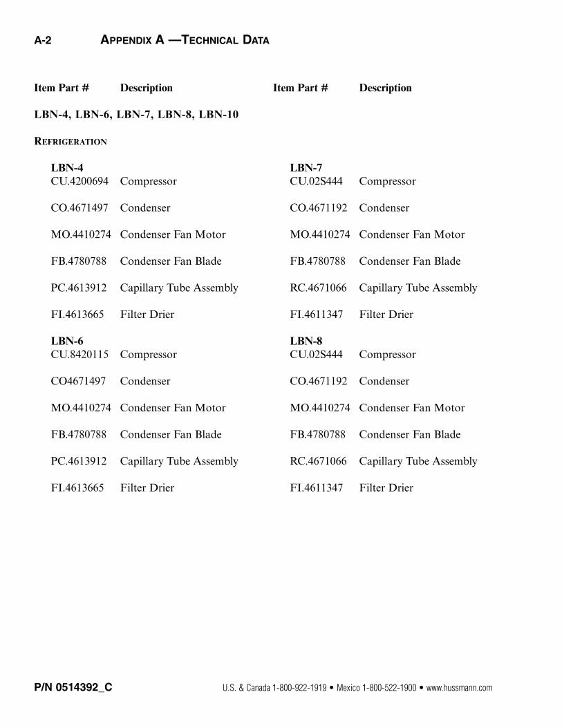
APPENDIX A — TECHNICAL DATA A-1
Item Part # Description
LBN-4, LBN-6, LBN-7, LBN-8, LBN-10
THERMOSTATS & POWER PLUG
CT.04S035 Refrigeration Thermostat
SW.4440541 Switch
EP.4481948 Power Cord, (all models except LBN-10)
TC.03S269 Defrost Timer, (48 Hours)All models except LBN-10
TC.03S072 Defrost Timer, (24 Hours)LBN-10
HEATERS
ALL MODELS
HE.4850897 Heater End Breaker(Right Side)
HE.4850910 Heater End Breaker (End Side)
CT.4480283 Defrost Heater Limit Thermostat
CT.4482440 Anti-Sweat Heaters Limit Thermostat
LBN-4HE.4850853 Defrost Heater
HE.4850944 Nose Heater
GL.4990294 Front Glass Pack with Heater
Item Part # Description
LBN-6HE.4850855 Defrost Heater
HE.4850914 Nose Heater
GL.4990293 Front Glass Pack with Heater
LBN-7HE.4850849 Defrost Heater
HE.4850959 Nose Heater
GL.4990304 Front Glass Pack with Heater
LBN-8HE.19S470 Defrost Heater
HE.4850911 Nose Heater
GL.4990291 Front Glass Pack with Heater
LBN-10HE.19S626 Defrost Heater
HE.4850924 Nose Heater
GL.4990291 Front Glass Pack with Heater
A-2 APPENDIX A —TECHNICAL DATA
Item Part # Description
LBN-4, LBN-6, LBN-7, LBN-8, LBN-10
REFRIGERATION
LBN-4CU.4200694 Compressor
CO.4671497 Condenser
MO.4410274 Condenser Fan Motor
FB.4780788 Condenser Fan Blade
PC.4613912 Capillary Tube Assembly
FI.4613665 Filter Drier
LBN-6CU.8420115 Compressor
CO4671497 Condenser
MO.4410274 Condenser Fan Motor
FB.4780788 Condenser Fan Blade
PC.4613912 Capillary Tube Assembly
FI.4613665 Filter Drier
Item Part # Description
LBN-7CU.02S444 Compressor
CO.4671192 Condenser
MO.4410274 Condenser Fan Motor
FB.4780788 Condenser Fan Blade
RC.4671066 Capillary Tube Assembly
FI.4611347 Filter Drier
LBN-8CU.02S444 Compressor
CO.4671192 Condenser
MO.4410274 Condenser Fan Motor
FB.4780788 Condenser Fan Blade
RC.4671066 Capillary Tube Assembly
FI.4611347 Filter Drier
P/N 0514392_C U.S. & Canada 1-800-922-1919 • Mexico 1-800-522-1900 • www.hussmann.com

HUSSMANN CORPORATION • BRIDGETON, MO 63044-2483 U.S.A. LBN Horizontal Merchandisers
APPENDIX A — TECHNICAL DATA A-3
Item Part # Description
LBN-10CU.8420119 Compressor
CO.25S040 Condenser
MO.4410827 Condenser Fan Motor
MO.4410274 Condenser Fan Blade
RC.4671479 Capillary Tube Assembly
FI.4611347 Filter Drier
LAMPS AND BALLASTS
BA.4480866 Ballast, LBN-4, 6
BA.4480870 Ballast, LBN-7, 8
BA.4483076 Ballast, (35W) LBN-10
BA.3383077 Ballast, (28W) LBN-10
Fluorescent LampReplace with like fixtures.
SW.4440541 Light Switch (LTH all models
Item Part # Description
LIDS ASSEMBLY
TP.4916574 Lids Assembly LBN-4, LBN-6, LBN-8
TP.4916574 Lids AssemblyLBN-7
TP.4915676 Lids AssemblyLBN-10
P/N 0514392_C U.S. & Canada 1-800-922-1919 • Mexico 1-800-522-1900 • www.hussmann.com
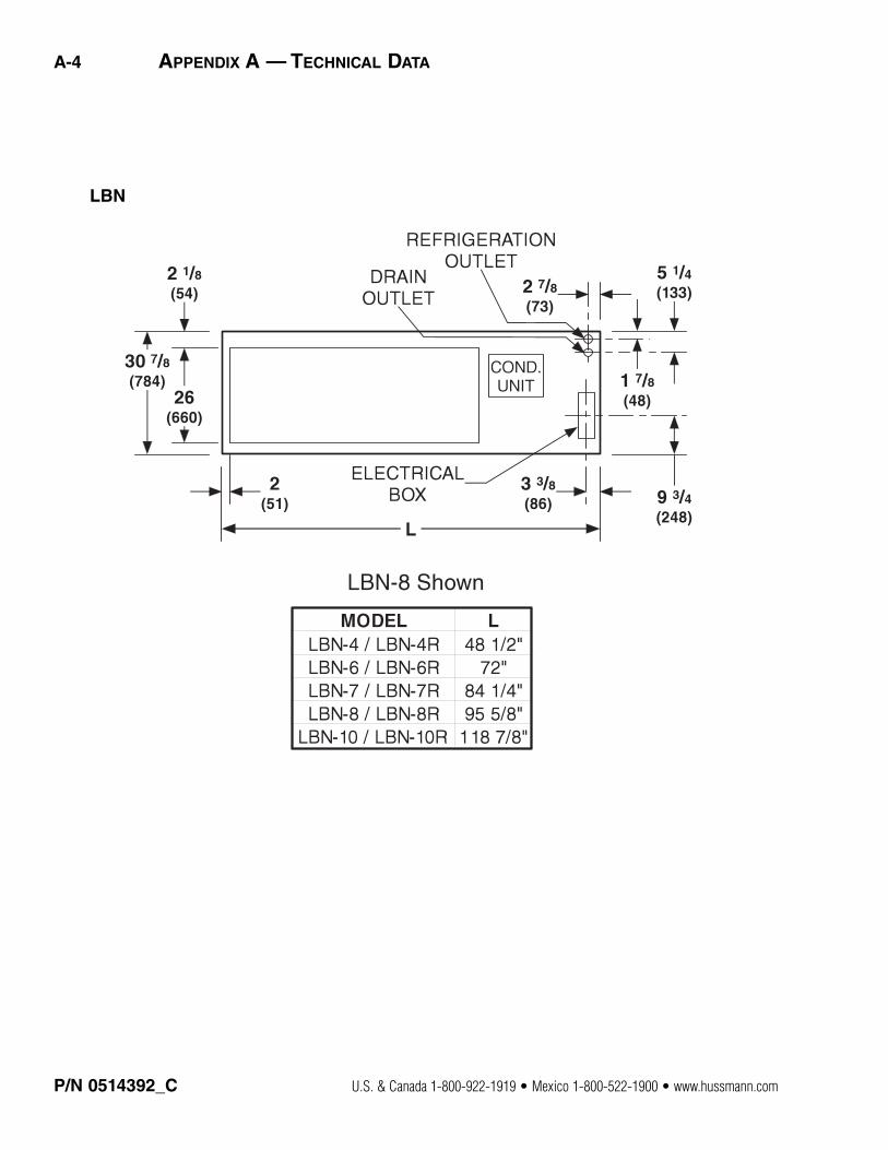
A-4 APPENDIX A — TECHNICAL DATA
LBN

HUSSMANN CORPORATION • BRIDGETON, MO 63044-2483 U.S.A. LBN Horizontal Merchandisers
REFRIGERATION DATA
LBN-4, LBN-6, LBN-7,LBN-8, LBN-10
ThermostatSetting CI/CO (°F)All Models 2:00 to 3:00 positions -4º F / -12º F
Compressor (hp)LBN-4 / LBN-6 1/2 hpLBN-7 3/4 hpLBN-8 / LBN-10 1 hp
Condensing Unit CapacityLBN-4 / LBN-6 3330LBN-7 3600LBN-8 / LBN-10 5400at -25º F evaporator and 110º F condenser temperature (Btu/hr at standard ASHRAE LBP rating conditions)
DEFROST DATA
Frequency (hr)LBN-4, 6, 7, 8 48LBN-10 24
OFFTIME
Failsafe (minutes)All models 40
Defrost TerminationTime Terminated
PHYSICAL DATA
Refrigerant Charge 30 oz 0.851 kg 36 oz 1.020 kg38 oz 1.077 kg35 oz 0.992 kg
LBN
Dimensions shown as inches and (mm).
Note: This data is based on storetemperature and humidity thatdoes not exceed 75°F and 55%R.H. unless otherwise stated.Schedule defrost at night whilelights are off.
APPENDIX A — TECHNICAL DATA A-5
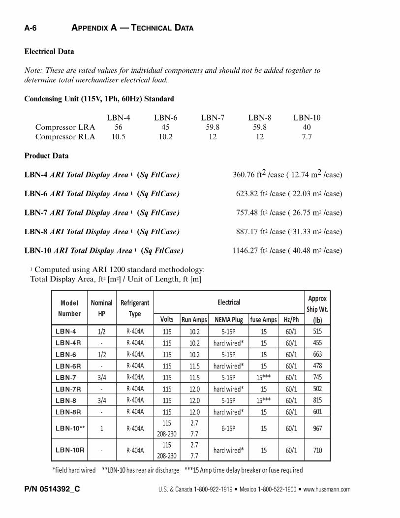
Electrical Data
Note: These are rated values for individual components and should not be added together to determine total merchandiser electrical load.
Condensing Unit (115V, 1Ph, 60Hz) Standard
LBN-4 LBN-6 LBN-7 LBN-8 LBN-10Compressor LRA 56 45 59.8 59.8 40Compressor RLA 10.5 10.2 12 12 7.7
Product Data
LBN-4 ARI Total Display Area 1 (Sq Ft/Case) 360.76 ft2 /case ( 12.74 m2 /case)
LBN-6 ARI Total Display Area 1 (Sq Ft/Case) 623.82 ft2 /case ( 22.03 m2 /case)
LBN-7 ARI Total Display Area 1 (Sq Ft/Case) 757.48 ft2 /case ( 26.75 m2 /case)
LBN-8 ARI Total Display Area 1 (Sq Ft/Case) 887.17 ft2 /case ( 31.33 m2 /case)
LBN-10 ARI Total Display Area 1 (Sq Ft/Case) 1146.27 ft2 /case ( 40.48 m2 /case)
1 Computed using ARI 1200 standard methodology:Total Display Area, ft2 [m2] / Unit of Length, ft [m]
P/N 0514392_C U.S. & Canada 1-800-922-1919 • Mexico 1-800-522-1900 • www.hussmann.com
Volts Run Amps NEMA Plug fuse Amps Hz/Ph
1/2 R-404A 115 10.2 5-15P 15 60/1 515
- R-404A 115 10.2 hard wired* 15 60/1 455
1/2 R-404A 115 10.2 5-15P 15 60/1 663
- R-404A 115 11.5 hard wired* 15 60/1 478
3/4 R-404A 115 11.5 5-15P 15*** 60/1 745
- R-404A 115 12.0 hard wired* 15 60/1 502
3/4 R-404A 115 12.0 5-15P 15*** 60/1 815
- R-404A 115 12.0 hard wired* 15 60/1 601
1 R-404A115
208-230
2.7
7.76-15P 15 60/1 967
- R-404A115
208-230
2.7
7.7hard wired* 15 60/1 710
*field hard wired **LBN-10 has rear air discharge ***15 Amp time delay breaker or fuse required
Approx
Ship Wt.
(lb)
ElectricalRefrigerant
Type
Nominal
HP
A-6 APPENDIX A — TECHNICAL DATA

HUSSMANN CORPORATION • BRIDGETON, MO 63044-2483 U.S.A. LBN Horizontal Merchandisers
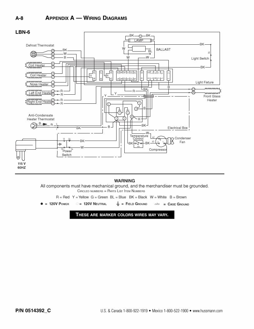
APPENDIX A — TECHNICAL DATA A-7
THESE ARE MARKER COLORS WIRES MAY VARY.
LBN-4
A-8 APPENDIX A — WIRING DIAGRAMS
P/N 0514392_C U.S. & Canada 1-800-922-1919 • Mexico 1-800-522-1900 • www.hussmann.com
THESE ARE MARKER COLORS WIRES MAY VARY.
LBN-6
HUSSMANN CORPORATION • BRIDGETON, MO 63044-2483 U.S.A. LBN Horizontal Merchandisers
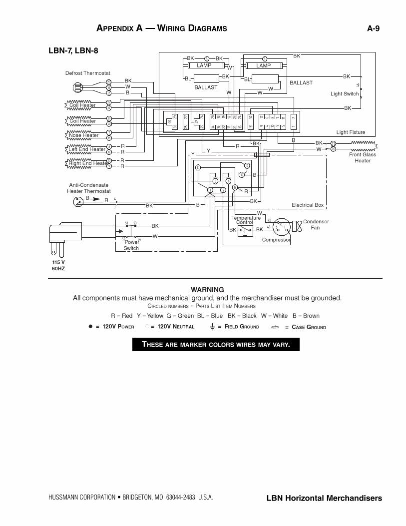
APPENDIX A — WIRING DIAGRAMS A-9
THESE ARE MARKER COLORS WIRES MAY VARY.
LBN-7, LBN-8
P/N 0514392_C U.S. & Canada 1-800-922-1919 • Mexico 1-800-522-1900 • www.hussmann.com
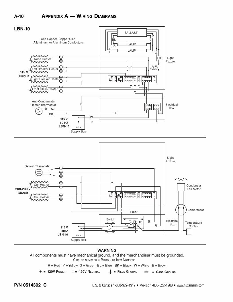
A-10 APPENDIX A — WIRING DIAGRAMS
LBN-10
®
To obtain warranty information or other support, contact your
Hussmann representative.Please include the model and serial number of the product.
Hussmann Corporation, Corporate Headquarters: Bridgeton, Missouri, U.S.A. 63044-2483 01 July 2005

Hussmann CorporationIngersoll Rand Climate Solutions12999 St. Charles Rock RoadBridgeton, MO 63044
www.hussmann.com