installation & initialisation - it dualism | my road to ... · business ethernet switch 1000...
TRANSCRIPT
Business Ethernet Switch 1000 Series Installation & Initialisation Task Based Guide

Installation & Initialisation
2 NN47910-304 Issue 1.0 BES1000
This page is intentionally left blank.
Installation & Initialisation
NN47910-304 Issue 1.0 BES1000 3
Table of Contents
Installation & Initialisation................................................ 5
Overview..........................................................................................5
Features Overview...........................................................................5 10/100/1000 Mbps Ports....................................................................................5 Simple Network Management Protocol (SNMP) ...............................................6 Mac Address Based Security.............................................................................6 Simple Network Time Protocol (SNTP) .............................................................6 Virtual LAN’s ......................................................................................................7 Rapid Spanning Tree Protocol (RSTP)..............................................................7 802.1p Class of Service Support .......................................................................7 Link Aggregation Control Protocol (LACP) ........................................................7
Required Information .......................................................................8
Flow Chart .......................................................................................9
Hardware Overview .......................................................................10 1. Console Port ................................................................................................10 2. Reset Button ................................................................................................11 3. Small Form Factor Pluggable Gigabit Interface Converters (SFP GBIC)....11 4. RJ-45 10/100/1000Mbps Ports ....................................................................11 LED’s ...............................................................................................................12
BES Application Examples ............................................................13 Simple Switch Application................................................................................13 Segmented Network Application......................................................................14 High Bandwidth/Density Application ................................................................14
Installing the BES Switch ...............................................................15 Desk or Shelf Mount ........................................................................................15 Rack Mount......................................................................................................16
Configuration Tools........................................................................17 Configuration Using a Web Browser................................................................17 Configuration Using Business Element Manager ............................................17 Installing BEM from a BCM50 Release 2.0 .....................................................17
Initialisation ....................................................................................25 Initialisation via Business Element Manager ...................................................25 Initialisation via a Web Browser.......................................................................31
Accessing the Web Page from Business Element Manager ..........36
Additional Actions .......................................................... 38
Changing the BES IP Address.......................................................38 Changing the IP Address via BEM ..................................................................38 Changing the IP Address via a Web Browser .................................................40

Installation & Initialisation
4 NN47910-304 Issue 1.0 BES1000
Rebooting the BES Switch.............................................................42 Rebooting the Switch via BEM ........................................................................42 Rebooting via a Web Browser .........................................................................43
Resetting the Switch to Default......................................................45 Defaulting the Switch via a Web Browser........................................................45 Defaulting the Switch Using the Reset Button.................................................46
Simple Network Time Protocol (SNTP)..........................................47 Configuring SNTP via BEM .............................................................................47 Configuring SNTP via a Web Browser.............................................................48
Nortel Documentation Links .......................................... 52
Installation & Initialisation
NN47910-304 Issue 1.0 BES1000 5
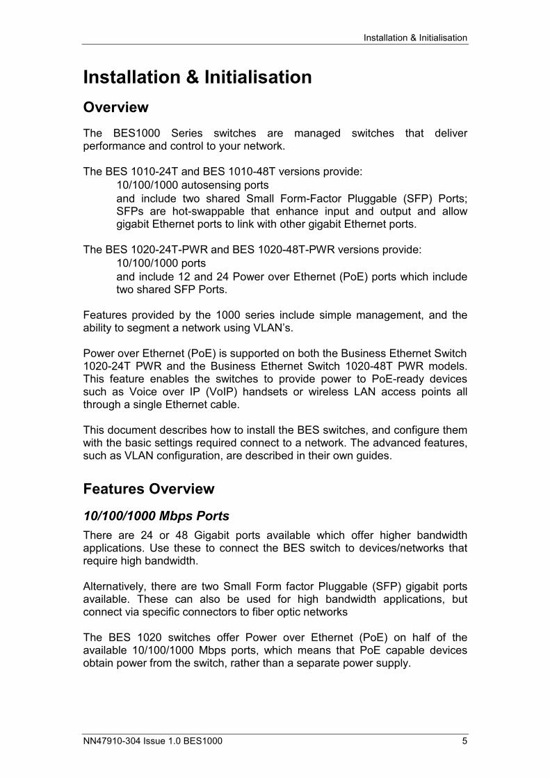
Installation & Initialisation Overview The BES1000 Series switches are managed switches that deliver performance and control to your network. The BES 1010-24T and BES 1010-48T versions provide:
• 10/100/1000 autosensing ports • and include two shared Small Form-Factor Pluggable (SFP) Ports;
SFPs are hot-swappable that enhance input and output and allow gigabit Ethernet ports to link with other gigabit Ethernet ports.
The BES 1020-24T-PWR and BES 1020-48T-PWR versions provide:
• 10/100/1000 ports • and include 12 and 24 Power over Ethernet (PoE) ports which include
two shared SFP Ports. Features provided by the 1000 series include simple management, and the ability to segment a network using VLAN’s. Power over Ethernet (PoE) is supported on both the Business Ethernet Switch 1020-24T PWR and the Business Ethernet Switch 1020-48T PWR models. This feature enables the switches to provide power to PoE-ready devices such as Voice over IP (VoIP) handsets or wireless LAN access points all through a single Ethernet cable. This document describes how to install the BES switches, and configure them with the basic settings required connect to a network. The advanced features, such as VLAN configuration, are described in their own guides.
Features Overview
10/100/1000 Mbps Ports There are 24 or 48 Gigabit ports available which offer higher bandwidth applications. Use these to connect the BES switch to devices/networks that require high bandwidth. Alternatively, there are two Small Form factor Pluggable (SFP) gigabit ports available. These can also be used for high bandwidth applications, but connect via specific connectors to fiber optic networks The BES 1020 switches offer Power over Ethernet (PoE) on half of the available 10/100/1000 Mbps ports, which means that PoE capable devices obtain power from the switch, rather than a separate power supply.
Installation & Initialisation
6 NN47910-304 Issue 1.0 BES1000
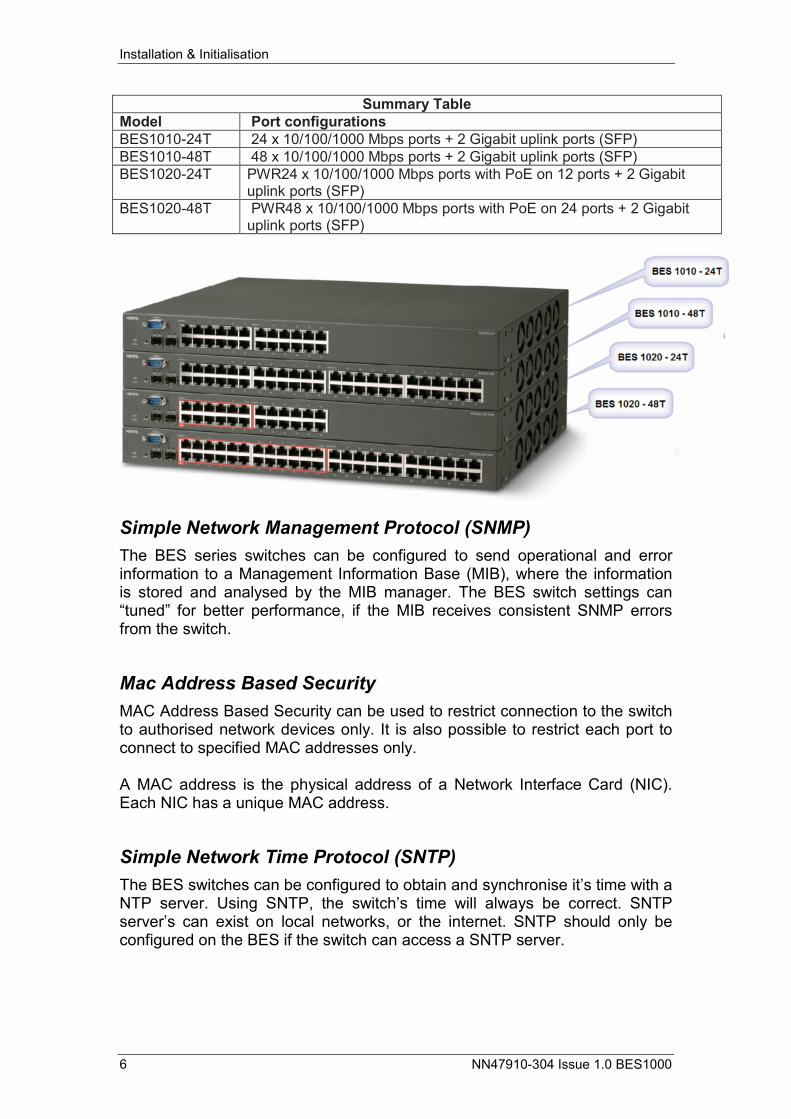
Summary Table Model Port configurations BES1010-24T 24 x 10/100/1000 Mbps ports + 2 Gigabit uplink ports (SFP) BES1010-48T 48 x 10/100/1000 Mbps ports + 2 Gigabit uplink ports (SFP) BES1020-24T PWR24 x 10/100/1000 Mbps ports with PoE on 12 ports + 2 Gigabit
uplink ports (SFP) BES1020-48T PWR48 x 10/100/1000 Mbps ports with PoE on 24 ports + 2 Gigabit
uplink ports (SFP)
Simple Network Management Protocol (SNMP) The BES series switches can be configured to send operational and error information to a Management Information Base (MIB), where the information is stored and analysed by the MIB manager. The BES switch settings can “tuned” for better performance, if the MIB receives consistent SNMP errors from the switch.
Mac Address Based Security MAC Address Based Security can be used to restrict connection to the switch to authorised network devices only. It is also possible to restrict each port to connect to specified MAC addresses only. A MAC address is the physical address of a Network Interface Card (NIC). Each NIC has a unique MAC address.
Simple Network Time Protocol (SNTP) The BES switches can be configured to obtain and synchronise it’s time with a NTP server. Using SNTP, the switch’s time will always be correct. SNTP server’s can exist on local networks, or the internet. SNTP should only be configured on the BES if the switch can access a SNTP server.
Installation & Initialisation
NN47910-304 Issue 1.0 BES1000 7
Virtual LAN’s A network can be segmented into separate logical groups, even though the network devices are connected to the same switch (or series of switches). Segmenting a network has the effect of reducing broadcast traffic between network devices, which will aid in the reduction of congestion. Also, some network Administrators prefer certain departments to be configured to separate logical networks (e.g. Sales on network range 192.168.1.X and Support on 200.10.10.X).
Rapid Spanning Tree Protocol (RSTP) If the BES is being installed in a multi-switch configuration, i.e. the BES is connected to other switches, broadcast storms can occur due to loops. This can have the effect of increasing congestion on the network. Rapid Spanning Tree Protocol is used to eliminate the loops, and thus reduce the possibility of broadcast storms. Rapid Spanning Tree Protocol is always operational on the BES switches, i.e. it cannot be enabled or disabled, and no configuration is required.
802.1p Class of Service Support The BES switches support the 802.1p standard of Class of Service. Network traffic can have a certain Differentiated Services Code Point (DSCP) value (between 0 & 63) which can have an associated priority value (0 – 7). The purpose of 802.1p is to offer prioritisation of certain network traffic, e.g. Voice over IP. To implement 802.1p Class of Service support, an understanding of DCSP values and their associated network traffic types is required.
Link Aggregation Control Protocol (LACP) LACP can be used to increase the link speed between the switch and e.g. a server if higher bandwidth is required between these two devices. In this example, the server would require two network cards that support LACP. The two network cards could both be connected to the BES switch, which with LACP enabled, can group the links together.

Installation & Initialisation
8 NN47910-304 Issue 1.0 BES1000
Required Information Before continuing with the installation and initialisation of the BES switches, you should try to obtain the following information:
• Where will the BES switch be installed? • The IP Address, subnet mask, and default gateway for the switch. The
IP Address will be used to access the management interfaces, and should be within the network range that the switch will be installed on.
Installation & Initialisation
NN47910-304 Issue 1.0 BES1000 9
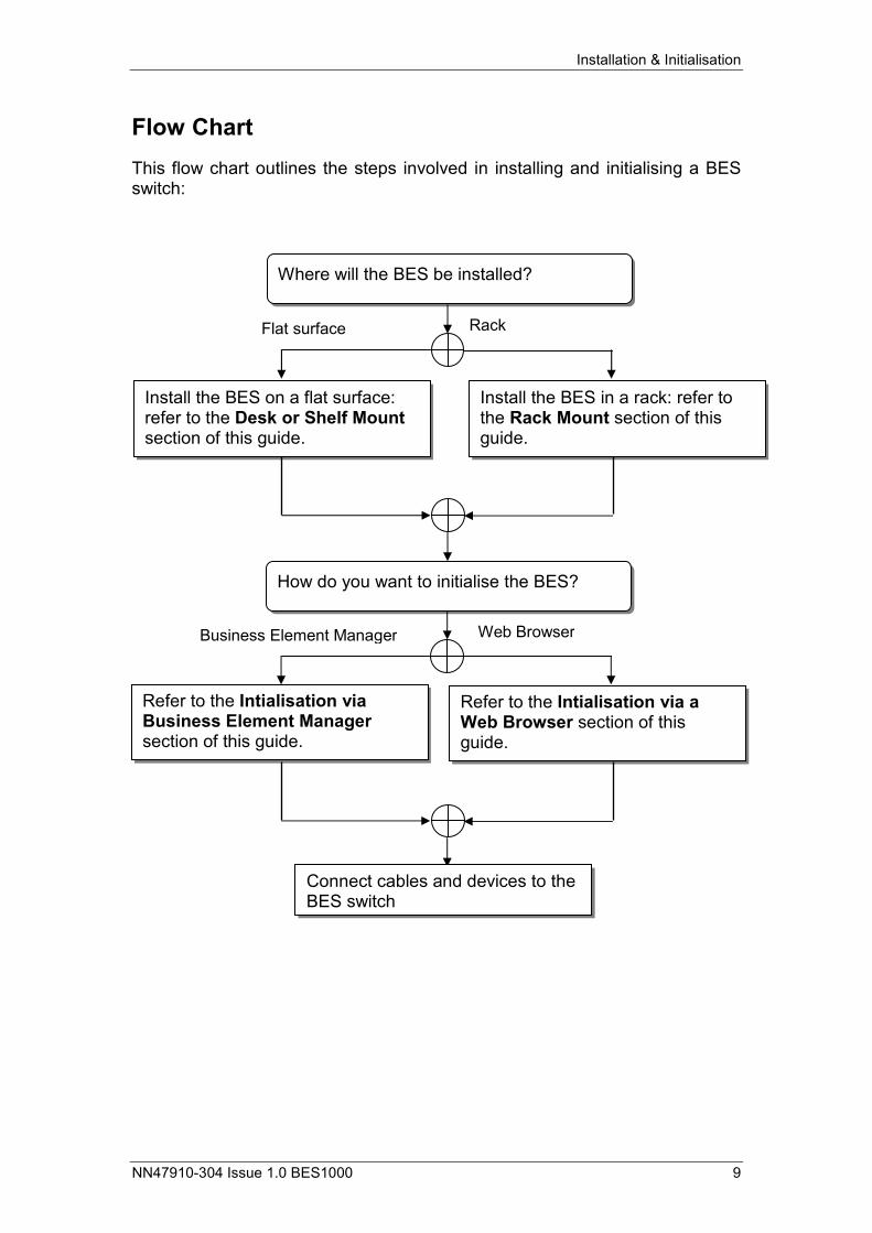
Flow Chart This flow chart outlines the steps involved in installing and initialising a BES switch:
Where will the BES be installed?
Flat surface Rack
Install the BES on a flat surface: refer to the Desk or Shelf Mount section of this guide.
Install the BES in a rack: refer to the Rack Mount section of this guide.
How do you want to initialise the BES?
Business Element Manager Web Browser
Refer to the Intialisation via Business Element Manager section of this guide.
Refer to the Intialisation via a Web Browser section of this guide.
Connect cables and devices to the BES switch
Installation & Initialisation
10 NN47910-304 Issue 1.0 BES1000
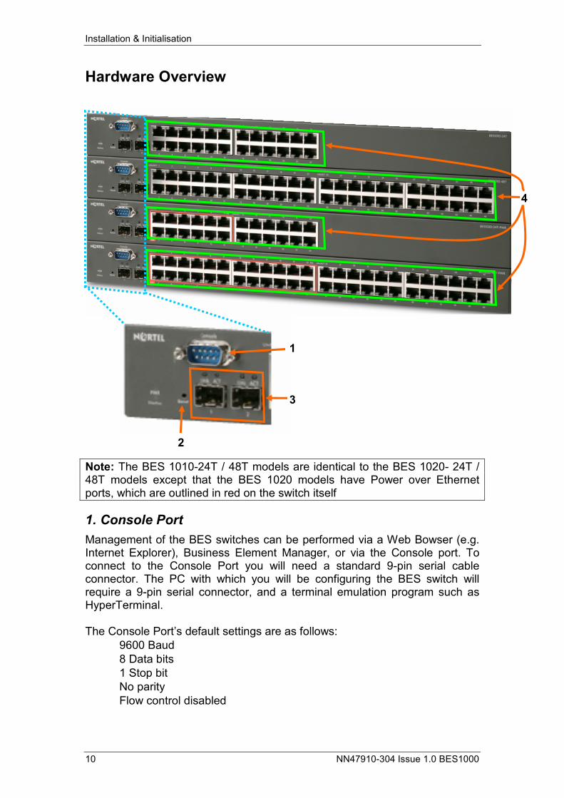
Hardware Overview
Note: The BES 1010-24T / 48T models are identical to the BES 1020- 24T / 48T models except that the BES 1020 models have Power over Ethernet ports, which are outlined in red on the switch itself
1. Console Port Management of the BES switches can be performed via a Web Bowser (e.g. Internet Explorer), Business Element Manager, or via the Console port. To connect to the Console Port you will need a standard 9-pin serial cable connector. The PC with which you will be configuring the BES switch will require a 9-pin serial connector, and a terminal emulation program such as HyperTerminal. The Console Port’s default settings are as follows:
• 9600 Baud • 8 Data bits • 1 Stop bit • No parity • Flow control disabled
2
3
1
4
Installation & Initialisation
NN47910-304 Issue 1.0 BES1000 11
2. Reset Button The Reset button resets the switch back to it’s factory default settings, i.e. it will erase any programmed data.
3. Small Form Factor Pluggable Gigabit Interface Converters (SFP GBIC) These two ports can be used in situations where high bandwidth is required, and where the connecting media is, for example, fiber optic cable. Special converters are required that plug in to the BES switch, which connect to the connecting media. The BES switches support the following SFP’s:
• 1000Base-SX SFP GBIC (mini-GBIC, connector type: LC) • 1000Base-SX SFP GBIC (mini-GBIC, connector type: MT-RJ) • 1000Base-LX SFP GBIC (mini-GBIC, connector type: LC)
4. RJ-45 10/100/1000Mbps Ports Connect network devices such as PC’s, printers, IP Phones etc. to these ports. The BES 110/210-24T, BES 120/220-24T have 24 ports, and the BES 110/210-48T and BES 120/220-48T have 48 ports available. The BES 120/220-24T and BES 120/220-48T have 12 and 24 ports respectively that can provide Power over Ethernet to any devices, e.g. IP Phones, that support PoE. These devices will therefore not require a local power supply. The PoE ports are outlined in red on the BES 120/220 switches. These ports are auto-sensing, i.e. they can detect the data transfer speed of the connected device and adjust accordingly, between 10Mbps and 100Mbps. When connecting to DTE (Data Terminating Equipment) devices such as a PC, a straight “patch” cable should be used. If connecting to DCE (Data Communication Equipment) devices such as other switches, a crossover cable should be used. CAT3 or CAT4 UTP cables can be used to connect to the switch, but note that these cables will only support data transfer rate of up to 10Mbps. To achieve 100Mbps, CAT5 cables should be used.
Installation & Initialisation
12 NN47910-304 Issue 1.0 BES1000
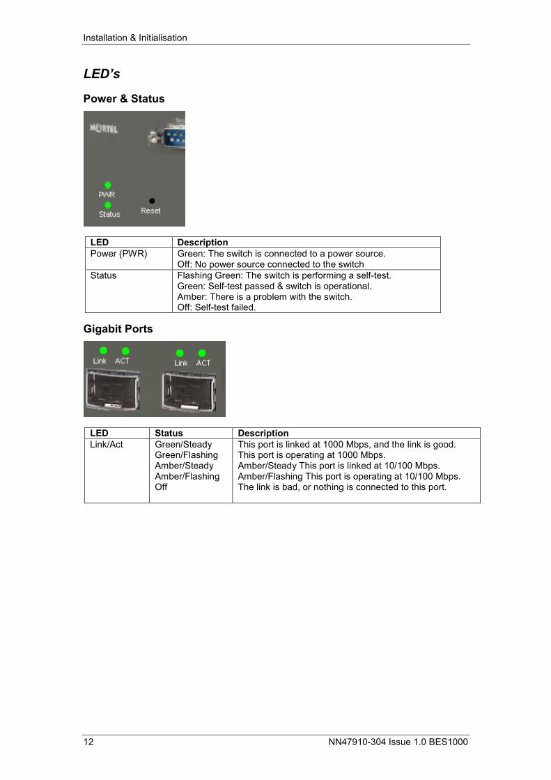
LED’s
Power & Status
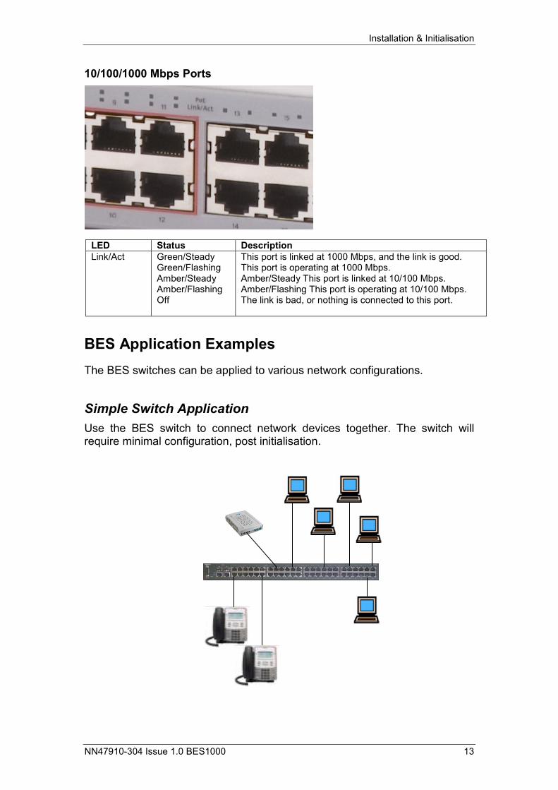
Gigabit Ports
LED Description Power (PWR) Green: The switch is connected to a power source.
Off: No power source connected to the switch Status Flashing Green: The switch is performing a self-test.
Green: Self-test passed & switch is operational. Amber: There is a problem with the switch. Off: Self-test failed.
LED Status Description Link/Act Green/Steady
Green/Flashing Amber/Steady Amber/Flashing Off
This port is linked at 1000 Mbps, and the link is good. This port is operating at 1000 Mbps. Amber/Steady This port is linked at 10/100 Mbps. Amber/Flashing This port is operating at 10/100 Mbps. The link is bad, or nothing is connected to this port.
Installation & Initialisation
NN47910-304 Issue 1.0 BES1000 13
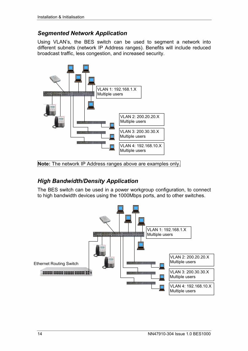
10/100/1000 Mbps Ports
BES Application Examples The BES switches can be applied to various network configurations.
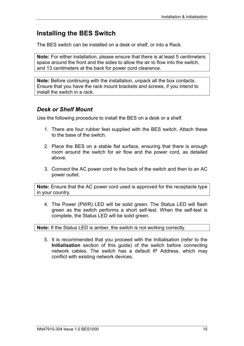
Simple Switch Application Use the BES switch to connect network devices together. The switch will require minimal configuration, post initialisation.
LED Status Description Link/Act Green/Steady
Green/Flashing Amber/Steady Amber/Flashing Off
This port is linked at 1000 Mbps, and the link is good. This port is operating at 1000 Mbps. Amber/Steady This port is linked at 10/100 Mbps. Amber/Flashing This port is operating at 10/100 Mbps. The link is bad, or nothing is connected to this port.
Installation & Initialisation
14 NN47910-304 Issue 1.0 BES1000
Segmented Network Application Using VLAN’s, the BES switch can be used to segment a network into different subnets (network IP Address ranges). Benefits will include reduced broadcast traffic, less congestion, and increased security.
Note: The network IP Address ranges above are examples only.
High Bandwidth/Density Application The BES switch can be used in a power workgroup configuration, to connect to high bandwidth devices using the 1000Mbps ports, and to other switches.
VLAN 2: 200.20.20.X Multiple users
VLAN 3: 200.30.30.X Multiple users
VLAN 4: 192.168.10.X Multiple users
VLAN 1: 192.168.1.X Multiple users
VLAN 2: 200.20.20.X Multiple users
VLAN 3: 200.30.30.X Multiple users
VLAN 4: 192.168.10.X Multiple users
VLAN 1: 192.168.1.X Multiple users
Ethernet Routing Switch
Installation & Initialisation
NN47910-304 Issue 1.0 BES1000 15
Installing the BES Switch The BES switch can be installed on a desk or shelf, or into a Rack. Note: For either installation, please ensure that there is at least 5 centimeters space around the front and the sides to allow the air to flow into the switch, and 13 centimeters at the back for power cord clearance.
Note: Before continuing with the installation, unpack all the box contacts. Ensure that you have the rack mount brackets and screws, if you intend to install the switch in a rack.
Desk or Shelf Mount Use the following procedure to install the BES on a desk or a shelf.
1. There are four rubber feet supplied with the BES switch. Attach these to the base of the switch.
2. Place the BES on a stable flat surface, ensuring that there is enough
room around the switch for air flow and the power cord, as detailed above.
3. Connect the AC power cord to the back of the switch and then to an AC
power outlet. Note: Ensure that the AC power cord used is approved for the receptacle type in your country.
4. The Power (PWR) LED will be solid green. The Status LED will flash green as the switch performs a short self-test. When the self-test is complete, the Status LED will be solid green.
Note: If the Status LED is amber, the switch is not working correctly.
5. It is recommended that you proceed with the Initialisation (refer to the Initialisation section of this guide) of the switch before connecting network cables. The switch has a default IP Address, which may conflict with existing network devices.
Installation & Initialisation
16 NN47910-304 Issue 1.0 BES1000
Rack Mount Use the following procedure if the BES is to be installed in a rack. Note: Before continuing, ensure that the rack is stable and that it has a grounded (earthed) connection.
Note: The BES switch fits into a standard 19-inch (48.2 centimeter) rack
1. The switch will require a 2.8 inch (6.25 centimeter) space in the rack.
2. Attach the brackets to the switch using the screws supplied with the switch.
3. Slide the switch into the rack, and fix to the rack using the screws
supplied with the rack.
4. Connect the AC power cord to the back of the switch and then to an AC power outlet.
Note: Ensure that the AC power cord used is approved for the receptacle type in your country.
5. The Power (PWR) LED will be solid green. The Status LED will flash green as the switch performs a short self-test. When the self-test is complete, the Status LED will be solid green.
Note: If the Status LED is amber, the switch is not working correctly.
6. It is recommended that you proceed with the Initialisation (refer to the Initialisation section of this guide) of the switch before connecting network cables. The switch has a default IP Address, which may conflict with existing network devices.
Installation & Initialisation
NN47910-304 Issue 1.0 BES1000 17
Configuration Tools There are three methods of configuring the BES: Console Port, Web Browser, and via Business Element Manager. This document describes configuration via a Web Browser, and via Business Element Manager (BEM).
Configuration Using a Web Browser To configure the BES switches, you should have one of the following Web Browsers installed on the configuration PC:
• Mozilla 5.0 on Windows 95, Windows 98, Windows 2000, Windows XP, or Windows NT 5.1; en-US; rv:1.8.0.3,
• Gecko 20060426; Firefox 1.5.0.3 • Mozilla 5.0, on Windows 95, Windows 98, Windows 2000, Windows
XP, or Windows NT 5.1; en-US; rv: 1.7.5, and UNIX • Gecko 20060127 • Netscape 8.1 • Internet Explorer 6.0
Configuration Using Business Element Manager Business Element Manager (BEM) will need to be installed on the configuration PC. BEM can be found on the Nortel web site (www.nortel.com) or can be found on the Release 2 version of a BCM50 (BCM50 R2). Note: Please contact your authorised Nortel distributor if you encounter problems obtaining Business Element Manager.
Installing BEM from a BCM50 Release 2.0 If you have access to a BCM50 R2, use the following procedure to download & install BEM.
1. Point your Web Browser at the BCM50 IP Address (http://10.10.11.1 if plugged into the OAM port.
Installation & Initialisation
18 NN47910-304 Issue 1.0 BES1000
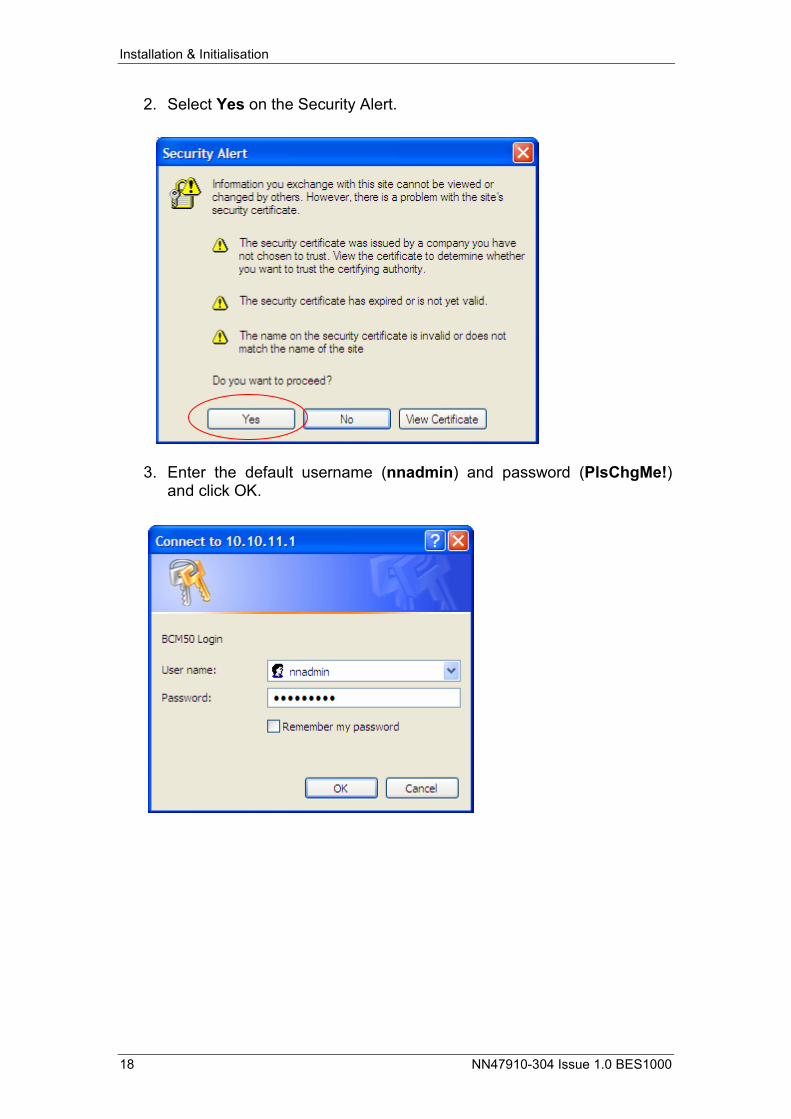
2. Select Yes on the Security Alert.
3. Enter the default username (nnadmin) and password (PlsChgMe!)and click OK.
Installation & Initialisation
NN47910-304 Issue 1.0 BES1000 19
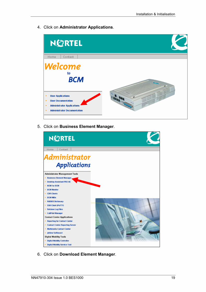
4. Click on Administrator Applications.
5. Click on Business Element Manager.
6. Click on Download Element Manager.
Installation & Initialisation
20 NN47910-304 Issue 1.0 BES1000
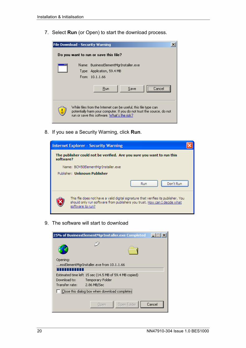
7. Select Run (or Open) to start the download process.
8. If you see a Security Warning, click Run.
9. The software will start to download