installation guideuk.siggroup.com/.../sig-webertherm-installation-guide.pdfthe installation guide...
TRANSCRIPT

External Wall InsulationInstallation Guide

2 SIG weber.therm External Wall Insulation Installation Guide
1.0 General Clauses 4
2.0 Preparation 5
3.0 System Detailing 6
4.0 Full System Beads and Trims 7
5.0 Boarding 8
6.0 Fixings 11
7.0 Render Only Beads 12
8.0 Meshcloth Coat 14
9.0 Rendering Materials 16
10.0 Brick Effect 17
11.0 Typical Details 18 - 39
Guidance & Advice for Maintaining 40 External Wall Insulation
Contents

3www.sig360retrofit.co.uk
The Installation Guide should be read entirely as it contains information on installation and application, desirable weather conditions, protection advice etc.
Please note it is the responsibility of the Installing contractor to form the project specific Method Statement that defines the appropriate schedule of works to reflect the project criteria.
Reference should be made to actual Product Data Sheets and Material Safety Data Sheets for additional relevant information.
If any specified operations do not seem applicable, or if a required operation is not included, clarification should be sought from the Architect / Engineer or SIG 360 RetroFit.

4 SIG weber.therm External Wall Insulation Installation Guide
1.0 GENERAL CLAUSES
1.1 RENDERS AND FINISHES
SIG products are made to Weber formulations. Components must not be substituted, omitted or added without specific approval.
1.2 STORAGE
• Dry bagged factory batched products must be stored off the ground and protected from water damage. All contain cement and are therefore made useless if affected by dampness.
• Stored under proper conditions, dry-bagged products have a shelf life of 12 months.
• Wet, pre-mixed materials must be stored frost free and protected from extreme heat. Generally containers should not be stacked more than 2 high. Where pallets are received on site with containers stacked 3 high these can be stored as is but nothing should be stored on top of them.
• Insulation products must be protected from rain and physical damage. Factory packaging does not provide a level of protection which would allow the materials to be stored outside.
1.3 MIXING
• Use paddle mixers and plastic drums.
• Discard suspect materials that are damp or contaminated.
• Don’t over mix. Only mix sufficiently to combine materials - then use immediately.
• Once material has been mixed do not attempt to re-temper it to a workable consistency by adding more water.
1.4 WEATHER CONSTRAINTS
COLD
• Don’t work with frosted materials or on frosted substrates.
• Do not apply any formless wet materials in temperatures below 5°C or when frost is likely to occur during a period of 24 hours after application, unless protection is provided.
• In cold weather, if frost is forecast, stop work in time to allow the material to set sufficiently to prevent frost damage. The drying conditions will vary according to wind, temperature and humidity and may take several hours.
• In frosty weather where minimum temperature conditions cannot be met work can only proceed when suitable protection is provided and the temperature has been raised.
WARM
• Do not work in high temperatures when flash setting of material may occur. In warm weather don’t work on sunny walls or walls which will become sunny. Apply material preferably after sun. During hot, rapid drying weather newly finished cementitous render materials may need to be actively cured by spraying with a light spray of clean water two or three times a day for two or three days after application. This is particularly relevant when working internally with these products.
WET
• Don’t work during rainfall or if rainfall is anticipated during initial set.
• Don’t allow rain to strike newly applied material, particularly if strong colours have been chosen for rendering.
1.5 PROTECTION
• Protect cementitous materials during their initial setting to prevent damage by rainfall. This can be done using tarpaulins, close mesh netting, polythene or other suitable material.
• Protect unset mortar against damage from overflows, unfinished rainwater outlets by providing appropriate temporary arrangements.
• Artificial enclosures round scaffolding can be formed using tarpaulins, close mesh netting, polythene or other suitable material to overcome adverse weather conditions.
• If artificial heat sources are used to maintain minimum temperatures care should be taken to ensure that steady temperatures are achieved and that hot/cold spots do not occur on the wall surface. The temperature range within the enclosure should be minimum 4ºC, maximum 10º deg C.

5www.sig360retrofit.co.uk
2.0 PREPARATION
2.1 HAMMER TEST
• Hammer test suspect wall surfaces and render areas to identify areas of defect.
• Hack off defective areas of wall surface until a solid substrate is achieved.
2.2 HACK OFF PROTRUSIONS
• Remove protrusions that affect the surface-plane of the wall.
• Use ‘MAKING GOOD’ procedure where there are large indented areas or where it is essential to restore surface plane. Use also where existing bellcast has been hacked off to facilitate the installation of new base bead by applying a leveling mortar to the wall and allowing it to dry.
2.3 PAINTSTRIP
• Apply proprietary paint remover suitable for masonry substrates to dissolve specified areas of oil-based or masonry paint. This should be applied to the manufacturer’s instructions and left for the time necessary for paint to soften. Scrape or brush off and thoroughly clean down surfaces to remove all traces of solvent. 75% minimum of paint must be removed before any stipple coat, mortar coat or insulation board can be applied.
2.4 POWERWASH
• Power wash wall surfaces to remove any ingrained dirt and dust. Use equipment of correct type and size and avoid continuously drenching the wall where possible. Thoroughly mask and protect window, door, vent and other apertures to prevent (or limit) water ingress.
2.5 MAKING GOOD
• Where required, hacked-off areas should be made good as follows:
• weber.rend stipple mortar is polymer modified for maximum bond to the substrate and should be stipple textured to a bold peaked texture - the rougher, the better.
• Mix weber.rend stipple to a thick creamy consistency simply by adding water only.
• Apply to bare areas using a banister brush, trowel, roller or specialist spray equipment. Work into surface and lay-off to a bold peak texture using a loaded brush or roller. Allow to fully dry and shrink. The drying period will vary with the weather conditions. Note: SIG weber.therm Adhesive can be used as an alternative to weber.rend stipple.
• Weber undercoat (scratch coat) (weber.rend TUC) is available.
• Mix Weber factory batched scratch coat mortar by adding clean water only to achieve workability. This mortar can be made up in any batch size desired with little wastage because it is pre-mixed dry. Add no other materials unless directed.
• Apply to prepared surface 10-12 mm thick and thoroughly scratch horizontally to produce key.
• Allow to dry and shrink completely before subsequent applications. This will depend on weather conditions, but normally requires a minimum of 36 hours.
2.6 FUNGICIDE
• Drench applies weber CL150 solution onto affected areas.
• weber CL150 is supplied ready for use in 5 and 25 litre containers.
• weber CL150 is best applied using a pressurised knapsack or garden sprayer but can be brush applied if areas are limited. weber CL150 must be left for a minimum of 48 hours to take effect and kill the growing moss and unseen spores. Dead growth should be removed by brushing with a stiff bristle or wire brush or alternatively by power washing.
• Wear protective clothes and/or safety equipment.

6 SIG weber.therm External Wall Insulation Installation Guide
3.0 SYSTEM DETAILING
3.1 REQUIREMENT FOR SOFT JOINTS / SEALS
• Soft joints should be incorporated where mineral render finishes interface with windows, doors, cills etc.
• Soft joints can be formed using PVC window frameseal, proprietary compressible seals or mastic in appropriate check.
3.2 PROPRIETARY PVC SEAL
• Where PVC window frameseal has been specified it should be installed after all preparatory works but prior to any boarding to affected areas.
• The PVC window frameseal incorporates a self-adhesive tape and this is used to bond it to the window / door frame and Installation is carried out as follows:
• Frames, to which PVC window frameseal is being bonded, must be dry, dust & grease free
• Remove approximately 100mm of the cover strip from the adhesive on the back of the profile. Carefully locate and install the profile on to the frame. Continue removing the cover strip and press the profile securely into position.
• Once PVC window frameseal has been installed around opening fix window / door protection to the sacrificial fin using the integrated double sided tape. When the rendering is complete remove protection along with the sacrificial fin.
3.3 PROPRIETARY EXPANDABLE
(PRE-COMPRESSED) SEALS
• Where the insulation abuts another material and a ‘soft’ joint is specified / required or where sealing tape is specified as part of a ‘joint’ appropriate sized gap should be created and an expandable (pre-compressed) sealing tape installed.
• Background, to which a proprietary expandable seal is being bonded, must be dry, dust & grease free.
• Seal is applied by removing protective paper and exposing the self-adhesive surface. The material will remain in its compressed form for several minutes (dependant on working temperatures) allowing plenty of time to position the tape before it begins to expand. All joints must be lapped to ensure continuity of seal.
3.4 MASTIC CHECK
• Where indicated on drawings, form nominal 6mm x 6mm recess in specified render coat between surfaces to be sealed.
3.5 PANEL SIZES
• Panel size varies dependant on a number of factors
• Movement joints provided in the substrate must not be bridged but expressed through the full build-up of the system being applied.
• In all cases the applicator should consider the following to ensure that the operatives are able to apply and finish a panel to a satisfactory standard:
• A suitable number of skilled operatives in proportion to the panel size that will enable a flowing wet edge to be maintained in applied material across the entire panel
• Suitability of access (to wall area) full access should be available between scaffold and the wall to enable a continuous wet edge of material to be maintained across the complete bay / elevation
• Expected weather conditions

7www.sig360retrofit.co.uk
4.0 FULL SYSTEM BEADS AND TRIMS
4.1 BASE BEAD (FULL SYSTEM)
• Determine position of base bead from detailed drawings. Normally this is on the line of the DPC.
• Set out the work to avoid small cuts, allowing for a nominal 2mm gap between sections to accommodate thermal expansion, and install bead as appropriate for substrate:
• Masonry substrates:
• Mount the specified bead against the wall, drilling through preformed holes in the bead and pinning with specified fixing at 700mm maximum centres.
• Sheathed substrates:
• Mount the specified bead against the sheathing board and fix through preformed holes in the bead using specified screw fixings at 700mm maximum centres.
• Aluminium box (full system) with this type of bead a proprietary clip on drip is required on the SIG weber.therm systems which incorporates a top coat.
4.2 STOP BEAD (FULL SYSTEM)
• Determine position of stop bead from detail drawing. Normally this is on line of a party wall adjacent to property in different ownership or up against a feature such as a door or window.
• Masonry substrates:
• Mount the specified bead against the wall, drilling through preformed holes in the bead and pinning with specified fixing at 700mm maximum centres.
• Sheathed substrates:
• Mount the specified bead against the sheathing board and fix through preformed holes in the bead using specified screw fixings at 700mm maximum centres.
• Don’t overdrive the fixings as this can distort the bead.
• Where bead incorporates PVC nosing this should be used to sleeve the joint. If jointing clips/sleeves are provided as part of bead design they should be used.
• Pack or bed where necessary to prevent bead spanning more than 300mm.
• Prepare wall surface and apply mastic, mastic tape or other bedding where specified to seal at wall.

8 SIG weber.therm External Wall Insulation Installation Guide
5.0 BOARDING
5.1 BOARDING GENERAL
• All insulation boards must be handled carefully and stored properly on a level, dry, surface and suitably protected against damage or prolonged wetting.
• It is normal practice to fix insulation boards to walls from the base upwards, starting from a corner and to soffits starting from a fixed edge (Boards in the main should be fitted with the long axis horizontal). There is no hard and fast rule and whatever practice is suitable and sensible can be adopted within the limitations of the system.
• The procedures detailed below must be followed:-
• Where straightening of the substrate is required this MUST be carried out, using appropriate materials, prior to installation of insulation.
• Set out the work to avoid small cuttings of board being used. Always avoid joint alignment with prominent features such as window cills. Cut boards must be minimum 250mm.
• Boards must be mounted broken bond with a minimum vertical offset of 250mm. It is normal practise to use half bond at the outset to accommodate various features that may be encountered.
• On walls boards must be mounted level. Failure to start from a good horizontal base will result in errors being compounded.
• On soffits start from a fixed straight edge and maintain alignment to prevent errors being compounded.
• Board joints must be close butted on all edges. Gaps must not exceed 6mm. Anything over this should be cut out and repacked with insulation or filled with expanding aerosol foam, cut off flush after cure.
• Check boards by removing material from back face, by cutting or paring to allow a neat fit over full-system beads, bolts, brackets etc. or round features or discrepancies which have minimal protrusion. The remaining portion of the board, which covers the projecting feature, must be at least 10mm or 1/3 of the board thickness whichever is the greater. Cut boards to fit - do not bash them into place hoping the insulation will give.
• Stagger butt joints at arrisses. Main corners can be straightened by sawing-off excess overhang after mounting. Normally the board to be cut is offered up to the wall, scribed, cut and then fixed with machined edge at arris.
5.2 FIREBREAKS
• Where horizontal firebreaks are required/ being provided, they consist of a band of mineral fibre insulation, minimum 100mm wide, of same thickness as main wall insulation placed horizontally in predetermined positions within the system.
• Where vertical firebreaks are required the Firebreak insulation is placed vertically always fixed with long edge vertical.
• When using lamella insulation it is common practise to form a 200mm wide firebreak rather than cut the insulation into two pieces.
• Determine their location by reference to detail and elevation drawings, contract documents or by confirmation of Architect / Supervising officer.
• Form firebreak as follows:
• Bed mineral fibre strips in SIG weber.therm Adhesive close butted to its neighbours and lightly tap into place to reconcile surface plane. Mineral fibre strips must be fully bedded to substrate to eliminate any gaps behind.
• When meshcloth coat has been applied, but before second pass of adhesive, specified fire resistant fixings for firebreak should be inserted through meshcloth coat and mineral fibre, near centre line of firebreak, at maximum 400mm centres.
• Apply nominal 100x100mm patch of meshcloth over head of fire fixings.
• Apply second pass of adhesive as per SIG weber.therm Meshcloth Coating’ item. This will involve the use of additional fixings in relation to specified fixing pattern.

9www.sig360retrofit.co.uk
5.0 BOARDING continued
Mechanically Fixed:
5.3 BOARDING TO MAIN AREAS
• The batts are mechanically fixed to the prepared, sound substrate with appropriate fixings.
• Factory batched SIG weber.therm Adhesive, which is mixed simply by adding clean water, is applied to the back of the insulation only where bedding is required to reconcile board edges (must NOT be used to straighten the substrate).
• Reconciling the board edges is important when using SIG weber.therm MFD & SIG weber.therm PIR as they cannot be planed to smooth-off the surface.
• The insulant is fixed to the ‘saltire’ fixing pattern (as below) using 5 fixings. Fixings are located in the centre of the board and one in each corner, approximately 150mm from board edge. Edge distance can be reduced to 75mm on cut boards.
5.4 MECHANICALLY FIXED - BOARDING TO REVEALS
• It is always desirable to insert insulation into a reveal, preferably of the same thickness as the main wall material. In practice this is not always possible particularly on existing buildings where the window is fixed and is not to be replaced.
• Narrow strips of insulation, which must be minimum 250mm long and of the thickness specified (20mm minimum) are cut to fit the reveal recess at the head and jambs. The strips are mechanically fixed to the reveal using specified fixings at 300mm (max.) centres.
• Bedding of boards, using SIG weber.therm Adhesive, should only be carried out if the surface is uneven and edges of boards have to be reconciled.
• An alternative procedure for reveal boarding involves cutting the main wall board on the line of the existing reveal and then installing the reveal board to lap the exposed edge.
• When using SIG weber.therm MFD insulation, corner reinforcing beads, as specified, must be installed before the meshcloth is applied. These are bedded as appropriate, using SIG weber.rend Adhesive to produce a straight arris.
• On deep reveals where the same type and thickness of insulation, is being used, a better finish can be achieved by staggering the butt joints.
Innovative • Creative • Technical External Wall Insulation and Render Solutions
weber.therm XM Installation
5.4 BOARDING TO MAIN AREAS
The batts are mechanically fixed to the prepared, sound substrate with appropriate fixings.
factory batched weber.rend LAC, which is mixed simply by adding clean water, is applied to the back of the insulation only where bedding is required to reconcile board edges (must NOT be used to straighten the substrate).
Reconciling the board edges is important when using weber.therm MFD & weber.therm PHS as they cannot be planed to smooth-off the surface.
The insulant is fixed to the ‘saltire’ fixing pattern (as below) using 5 fixings. Fixings are located in the centre of the board and one in each corner, approximately 150mm from board edge. Edge distance can be reduced to 75mm on cut boards.
5.5 MECHANICALLY FIXED - BOARDING TO REVEALS
It is always desirable to insert insulation into a reveal, preferably of the same thickness as the main wall material. In practice this is not always possible particularly on existing buildings where the window is fixed and is not to be replaced.
Narrow strips of insulation, which must be minimum 250mm long and of the thickness specified (20mm minimum) are cut to fit the reveal recess at the head and jambs. The strips are mechanically fixed to the reveal using specified fixings at 300mm (max.) centres.
Bedding of boards, using weber.rend LAC, should only be carried out if the surface is uneven and edges of boards have to be reconciled.
An alternative procedure for reveal boarding involves cutting the main wall board on the line of the existing reveal and then installing the reveal board to lap the exposed edge.
When using weber.therm MFD/MFS insulation, corner reinforcing beads, as specified, must be installed before the meshcloth is applied. These are bedded as appropriate, using weber.rend LAC to produce a straight arris.
On deep reveals where the same type and thickness of insulation, is being used, a better finish can be achieved by staggering the butt joints.
5.0 BOARDING cont...
9

10 SIG weber.therm External Wall Insulation Installation Guide
5.0 BOARDING continued
5.5 ADHESIVE BONDED - BOARDING MAIN AREAS
• Adhesive fixing is in order with plain SIG weber.therm EPS & SIG weber.therm PIR insulation boards.
• The batts must be stuck to the prepared, sound substrate to restrain the boards from moving and causing cracking in the rendering.
• Mix factory batched SIG weber.therm Adhesive simply by adding water only. The mix is best produced using a plastic or rubber drum and a paddle mixer.
• Apply the mortar to the back of the insulation boards in 4 strips vertically, about 100mm wide x 25mm - 30mm thick, such that when board is applied to the prepared substrate, at least 50% of the surface area of the board is adhered.
• Place the board in position, close butting it with its neighbour and tap lightly into position. Reconcile edges to minimise protrusions (this is critical with SIG weber.therm PIR boards as they cannot be surformed).
• After nominal 24 hours setting time, drill and insert supplementary fixing pins to hold board in position while mortar achieves full set. Normally two plastic pins are inserted on the longitudinal centre line of the board, or part board, but individual specifications may call for more.
5.6 ADHESIVE BONDED - BOARDING TO REVEALS
• It is always desirable to insert insulation into a reveal, preferably of the same thickness as the main wall material. In practice this is not always possible particularly on existing buildings where the window is fixed and is not to be replaced.
• Narrow strips of insulation, which must be minimum 250mm long and of the thickness specified (20mm minimum) are cut to fit the reveal recess at the head and jambs. SIG weber.therm Adhesive is applied to the back and the strips bedded in place. Supplementary mechanical fixings, as specified, are inserted at this stage.
• An alternative procedure for reveal boarding involves cutting the main wall board on the line of the existing reveal and then installing the reveal board to lap the exposed edge.
• When using SIG weber.therm MFD insulation, corner reinforcing beads, as specified, must be installed before the meshcloth is applied. These are bedded as appropriate, using SIG weber.therm Adhesive to produce a straight arris.
• On deep reveals where the same type and thickness of insulation, is being used, a better finish can be achieved by staggering the butt joints.
• With polystyrene insulation plane-off any high spots using a Surform plane when the adhesive mortar has set thoroughly.
Innovative • Creative • Technical External Wall Insulation and Render Solutions
weber.therm XMInstallation
5.6 ADHESIVE BONDED - BOARDING MAIN AREAS
Adhesive fixing is in order with plain weber.therm EPS & weber.therm PHS insulation boards.
The batts must be stuck to the prepared, sound substrate to restrain the boards from moving and causing cracking in the rendering.
Mix factory batched weber.rend LAC simply by adding water only. The mix is best produced using a plastic or rubber drum and a paddle mixer.
Apply the mortar to the back of the insulation boards in 4 str ips vertically, about 100mm wide x 25mm - 30mm thick, such that when board is applied to the prepared substrate, at least 50% of the surface area of the board is adhered.
Place the board in position, close butting it with its neighbour and tap lightly into position. Reconcile edges to minimise protrusions (this is critical with weber.therm PHS boards as they cannot be surformed).
After nominal 24 hours setting time, drill and insert supplemen-tary fixing pins to hold board in position while mortar achieves full set. Normally two plastic pins are inserted on the longitudinal centre line of the board, or part board, but individual specifications may call for more.
5.7 ADHESIVE BONDED - BOARDING TO REVEALS
It is always desirable to insert insulation into a reveal, preferably of the same thickness as the main wall material. In practice this is not always possible particularly on
existing buildings where the window is fixed and is not to be replaced.
Narrow strips of insulation, which must be minimum 250mm long and of the thickness specified (20mm minimum) are cut to fit the reveal recess at the head and jambs. weber.rend LAC is applied to the back and the strips bedded in place. Supplementary mechanical fixings, as specified, are inserted at this stage.
An alternative procedure for reveal boarding involves cutting the main wall board on the line of the existing reveal and then installing the reveal board to lap the exposed edge.
When using weber.therm MFD/MFS insulation, corner reinforcing beads, as specified, must be installed before the meshcloth is applied. These are bedded as appropriate, using weber.rend LAC to produce a straight arris.
On deep reveals where the same type and thickness of insulation, is being used, a better finish can be achieved by staggering the butt joints.
With polystyrene insulation plane-off any high spots using a Surform plane when the adhesive mortar has set thoroughly.
5.0 BOARDING cont...
10

11www.sig360retrofit.co.uk
6.0 FIXINGS
6.1 FIXINGS GENERAL
• SIG selects fixings for their ability to support the dead load of the system and resist dynamic forces such as wind. Fixings are selected for their ability to perform on a longterm basis and for their compatibility with other materials.
• Fixing strength can easily be verified by means of a pull-out meter. Tests should be carried out where any doubt exists or where the substrate is poor or of variable quality. Fixings are available in a variety of lengths in each type to suit particular applications.
• They are normally designed to work in designated substrates. The workability of fixings in certain substrates can be improved by increasing or decreasing the drill bit size. The performance of the fixing must not fall below required levels for pull out resistance.
• Where ‘drill and drive’ and ‘stand-off’ fixings are being used in masonry substrates care must be taken to ensure hole is drilled to correct depth for the particular fixing sleeve. Incorrect hole depth can have a detrimental effect on the performance of the fixing.
• SIG recommends the use of a proper depth gauge when drilling into masonry substrates.
• When inserting insulation fixings care must be taken not to overdrive – fixing must hold insulation against substrate.
6.2 FIRE FIXINGS
• Where external wall insulation systems are being used on buildings of 3 storeys and over, 1 fixing per square metre MUST be a fire resistant type as specified. These fixings, which are inserted through the meshcloth, are not included in the specified fixing rate.
• All in accordance with current BRE guidelines.
6.3 DRILL AND DRIVE PLASTIC - POSITIVE EXPANSION
• Polypropylene hollow sleeve complete with expansion dowel. Sleeve is tapped into the hole until the head of the
6.4 ‘T’ BREAK FIXING - POSITIVE EXPANSION
• Hollow polyethylene sleeve incorporating thermal break tube complete with metal centre pin which has a coloured polyamide head thermal break head. Sleeve is tapped into the hole until the head of the fixing is against the lath / insulation. Positive expansion is provided by tapping in the centre pin.
6.5 DRILL AND DRIVE STAINLESS HOLLOW WEDGE
• Stainless hollow spring wedge fixing. Hammered into the hole until the head of the fixing is against the lath / meshcloth.

12 SIG weber.therm External Wall Insulation Installation Guide
7.0 RENDER ONLY BEADS
7.1 SURFACE BEADS
• Surface beads are used where the panel is being divided into different areas of colour or texture, or as a control joint between elements of the building structure.
• They consist of vertical stop and horizontal drip beads. Mitre horizontal and vertical beads. Where bead incorporates PVC nosing this should be used to sleeve the joint. If jointing clips/sleeves are provided as part of bead design they should be used.
7.2 RENDER ONLY STOP, DRIP AND MOVEMENT BEADS
• Fix beads by one of the following methods:
• Bedding in mortar prior to rendering. Allow to set properly to avoid disturbance by subsequent coating application.
• Using weber plastic restraining button fixing in SIG weber.therm System.
• Always maintain alignment of beads at butt joints
7.3 CORNER BEADS
• These beads are used mainly to facilitate the formation of a straight arris at main wall corners and in reveals where a polymer modified topcoat is to be applied on to the meshcloth coat.
• Fix beads in position indicated as follows:
• After the boarding has been installed and prior to application of meshcloth coat, bed the bead in adhesive mortar and press home gently, to avoid distortion, to form line of arris.
• Set out the work to avoid small cuts. Ensure beads are level or plumb and present an even appearance to the eye.
7.4 MESH WING BEAD REVEALS
• In situations where reveals are to be formed in the thickness of the insulation, with a rendered finish, these can be formed using the appropriate mesh winged corner bead.
• Cut bead to appropriate lengths for reveal and head, allowing sufficient length to form mitre joint in meshcloth wing on main wall insulation face
• Neatly cut one wing of meshcloth wing bead to suit insulation thickness (reveal depth) - other wing should be left uncut
• Bed cut lengths onto wall using SIG weber.therm Adhesive and ensure both mesh wings are flat and wrinkle free.
• Apply second pass of SIG weber.therm Adhesive to reveal wing of bead, to achieve specified thickness (5 or 6mm) and sufficient to prevent meshcloth ‘grinning’ through. Finish coat as appropriate for subsequent material application.
• If beads are being installed some time before main wall meshcloth application then key surface of meshcloth sandwich otherwise remove all trowel marks ready to take main wall meshcloth application which must be lapped over
13www.sig360retrofit.co.uk
7.0 RENDER ONLY BEADS cont...
7.5 TWO-PART HORIZONTAL COMPRESSION JOINT
• The two-part Horizontal Compression Joint comprises a PVC channel profile top section & coated aluminium bottom section. The joint profile is installed to weather a compression joint in the substrate which has been expressed through the insulation board. The maximum joint width which can be protected with this profile is 15mm.
• Before installing on to insulation / substrate board connect the PVC top & coated aluminium bottom sections by inserting the top flange, plain un-perforated leg, of the bottom section in to the slot in the top section with the projecting ‘knuckle’ facing outwards.
• The exposed perforated leg of the bottom section is then bedded on to the insulation / substrate board forming the bottom of the compression joint using SIG weber.therm Adhesive and positioned so that the bottom edge of the projecting ‘knuckle’ is aligned with the top edge of the lower insulation / substrate board forming the compression joint in the system. The bedding mortar must be allowed to set to ensure the bottom section is restrained before completing the installation.
• Once the bedding mortar has set the joint can be set to the required width by sliding a piece of plywood, or equivalent, of the appropriate width along the length of the joint to separate the top & bottom sections accordingly. The maximum joint width which can be accommodated is 15mm.
• The meshcloth coat is then applied to the upper panel. During application of the 1st pass of SIG weber.therm Adhesive the mesh wing of the upper joint section is gently pulled away from the PVC bead to allow the mortar to be applied down over the top ledge of the PVC section. The mesh wing is pushed in to the adhesive mortar and the main wall meshcloth, on the upper panel, is then lapped down over the mesh wing and bedded in the adhesive mortar – this operation may require application of additional mortar over the mesh wing of the top section.

14 SIG weber.therm External Wall Insulation Installation Guide
8.0 MESHCLOTH COAT
8.1 HEAVY DUTY MESHCLOTH
• Where heavy-duty meshcloth is required, this must be applied first, after the first pass of adhesive mortar. Heavy duty mesh should be butt jointed, including at corners, it must not be lapped.
• Following the second pass of adhesive, bed in the standard mesh as detailed in the next item.
• Overall thickness of meshcloth coat incorporating both heavy duty and standard layers must be adequate to prevent meshcloth grinning through.
8.2 STANDARD MESHCLOTH COATING
• Weber coated glass fibre meshcloth is applied to the boarded substrate using factory batched SIG weber.therm Adhesive. The mix, which simply requires the addition of clean water, is best produced using a plastic or rubber drum and a paddle mixer.
• Coat boards with SIG weber.therm Adhesive to a thickness of 3mm and lay in the meshcloth. Work well into the wet mortar with the trowel. Once initial coat has started to take-up overcoat with a subsequent layer of SIG weber.therm Adhesive to produce a ‘sandwich’ about 6mm thick to totally encapsulate the meshcloth - this coat must be adequate to prevent the meshcloth grinning through. Where a polymer render topcoat is being applied thoroughly scratch the surface horizontally, to produce mechanical key, before the mortar sets.
• Where SIG weber.therm Brick Effect is being applied a light comb-scratch key is required and where thin decorative texture finishes are being applied must be finished with a sponge float; leaving the work flat off the trowel or finishing with a spatula or steel trowel will inhibit bond of the two materials. A figure of eight motion should be adopted with a suitable sponge float across all the freshly applied render as it starts to take up a light key should be produced.
• Do not attempt to use long lengths of meshcloth - it can become difficult to handle.
• Over laps should be 100mm in either direction.
• Take care to form corners tightly to avoid bulging.
• Meshcloth patches, nominal 250mm square, must be incorporated at corners of all openings (stress points)
Innovative • Creative • Technical External Wall Insulation and Render Solutions
weber.therm XMInstallation
8.1 HEAVY DUTY MESHCLOTH
Where heavy-duty meshcloth is required, this must be applied first, after the first pass of adhesive mortar. Heavy duty mesh should be butt jointed, including at corners, it must not be lapped.
Following the second pass of adhesive, bed in the standard mesh as detailed in the next item.
Overall thickness of meshcloth coat incorporating both heavy duty and standard layers must be adequate to prevent meshcloth grinning through.
8.2 STANDARD MESHCLOTH COATING
Weber coated glass fibre meshcloth is applied to the boarded substrate using factory batched weber.rend LAC. The mix, which simply requires the addition of clean water, is best produced using a plastic or rubber drum and a paddle mixer.
Coat boards with weber.rend LAC to a thickness of 3mm and lay in the meshcloth. Work well into the wet mortar with the trowel. Once initial coat has started to take-up o v e r c o a t w i t h a subsequent layer of weber . rend LAC to produce a 'sandwich' about 6mm thick to totally encapsulate the meshcloth - this coat must be adequate to prevent the m e s h c l o t h g r i n n i n g through. Where a polymer render topcoat is being applied thoroughly scratch the surface horizontally, to produce mechanical key, before the mortar sets.
Where weber.rend RB is being applied a light comb-scratch key is required and where thin decorative texture finishes are being applied must be finished with a sponge float; leaving the work flat off the trowel or finishing with a spatula or steel trowel will inhibit bond of the two materials. A figure of eight motion should be adopted with a suitable sponge float across all the freshly applied render as it starts to take up a light key should be produced.
Do not attempt to use long lengths of meshcloth - it can become difficult to handle.
Over laps should be 100mm in either direction. Take care to form corners tightly to avoid
bulging. Meshcloth patches, nominal 250mm square,
must be incorporated at corners of all openings (stress points)
8.0 MESHCLOTH COAT
14

15www.sig360retrofit.co.uk
8.0 MESHCLOTH COAT cont...
8.3 BOXED END REVEALS
• In situations where reveals are to be formed in the thickness of the insulation, with a rendered finish, the following applies.
• Cut meshcloth into strips approximately 500mm wide and bed 200mm width onto wall using Adhesive Coat with selvedge projecting over opening.
• Once main wall boarding has been fixed coat exposed edge and part face with Adhesive Coat and neatly bed in selvedge of meshcloth. When using SIG weber.therm MFD board corner reinforcement bead must be bedded onto external arris prior to fixing meshcloth selvedge.
8.4 SIG weber.therm System - MESHCLOTH APPLICATION TO REVEALS
• Meshcloth in reveals can be applied:
• By coating the reveal with SIG weber.therm Adhesive and returning the main wall meshcloth into the reveal.
• Or by installing the reveal meshcloth as a ‘bandage’, bedded into the reveal and on to the main wall surface prior to the main wall meshcloth application. This strip should lap onto the main wall insulation by 150mm (min). The main wall meshcloth is then lapped and applied over the reveal strip when it is still ‘green’.
• Once the main wall meshcloth is in place, prior to application of subsequent layer of SIG weber.therm Adhesive, bed in 250mm square patches of meshcloth on main wall at corners of opening. These are then covered by subsequent application of adhesive mortar.
• Where meshcloth is to be used to form a render-only reveal (where there is no room for insulation) the existing reveal must be thoroughly cleaned down and any paint removed.
• Where required to provide a sound in-plane surface making good should be carried out in accordance with the guidance given in the “PREPARATION” section of this part of the document. Any making-good must be allowed to fully dry and shrink before proceeding with the application of the meshcloth. Meshcloth is best applied in bandage form. Care must be taken to ensure that the bedding coat is thoroughly applied to a full 3mm thickness to avoid cracking.
8.5 FINISHING SIG weber.therm Adhesive TO RECEIVE TEXTURED SYNTHETIC COATINGS
• SIG weber.therm Adhesive must be finished with a sponge float; leaving the work flat off the trowel or finishing with a spatula or steel trowel will inhibit bond of the two materials. A figure of eight motion should be adopted with a suitable sponge float across all the freshly applied render as it starts to take up.
8.6 FIRE FIXINGS
• Where the specification calls for fire fixings they should be inserted, at the rate of 1/m2 (minimum), through the meshcloth before the second pass of SIG weber.therm Adhesive. These fixings are in addition to the main wall fixings installed at boarding stage.
• As these fixings have metal heads or washer they must have a patch of weber meshcloth standard, approximately 100mm square, applied over them. The meshcloth patch should be bedded in the second pass of adhesive mortar.
• If the specification does not call for fixings through the meshcloth coat, do not insert them without first consulting the architect/ supervising officer and SIG
16 SIG weber.therm External Wall Insulation Installation Guide
9.0 RENDERING MATERIALS
9.1 SIG weber.therm Dash Receiver (TOP COAT)
• Mix Weber factory batched top coat mortar by adding clean water only to achieve workability.
• Apply to undercoat 6mm thick
• Finish with selected dry dash or plain finish using float and sponge to take subsequent special finish.
9.1.1 DRY DASH
• Use only clean, properly graded aggregates from an approved source. SIG aggregates are washed and bagged before delivery to site.
• Aggregates should be damp before dashing onto mortar topcoat.
• Aggregate droppings can only be re-used if collected on a proper tray or sheet material, and thoroughly washed in running water over a sieve or screen.
• Dashing must be evenly applied to mortar of correct consistency. Care must be taken to avoid lift marks or unsightly thickening at beads and arrises.
• Bead nosing’s must be cleaned down directly following dashing application.
• Care must be taken to maintain a wet edge particularly in warm weather.
9.1.2 PLAIN FINISH
• Plain finish should be achieved using a float and sponge, working the surface when the surface has taken up sufficiently. Avoid splashing coloured mortars with water when working as this can wash out pigment and give a bleached effect.
• SIG mortars have minimal fissuring problems when floated smooth compared with conventional renders. Some minor fissuring may however occur.
• Self-coloured finishes can often be achieved using SIG coloured mortar in pale, pastel colours.
• Bead nosing’s must be cleaned down directly following application.
• Care must be taken to maintain a wet edge particularly in warm weather
• Where plain finish is to be followed by the subsequent application of a textured finish a light key should be produced using a sponge.
9.2 SIG weber.therm Silicone Finish
• Depending on the climatic and drying conditions, a period of 3 to 7 days must pass before progressing with the system installation from the finishing of the SIG weber.therm Adhesive to priming.
• Prime the prepared surface using SIG weber.therm Primer tinted primer applied by brush, spray or roller. Ensure complete coverage of wall to be treated to prevent ‘grinning through’ of the background. Primer is of low viscosity and easily applied.
• Primer should be applied at least 24 hours prior to application of SIG weber.therm Silicone Finish.
• Check batch numbers and colours of material required to complete the working area. Stir well in buckets and make minor adjustments to workability with a little water, thoroughly mixed in.
• Apply with a steel float and hawk to work area. Texture surface using thin plastic float to produce desired texture.
• Evenness of cover and texture are of paramount importance.
• Maintain a steady flow of application and keep a wet edge on all incomplete edges.
• Weather conditions for applying and drying are critical. Dry weather may not be enough if the humidity is high and the drying potential of the atmosphere is low. A dry atmosphere which can be foreseen for about 36 hours is preferred to effect initial curing and prevent wash-off. Polymer mixes stain and are difficult to remove.
17www.sig360retrofit.co.uk
10.0 BRICK EFFECT
• 10.1 SIG weber.therm Brick Effect Finish
• Ensure that the Adhesive has been lightly comb-scratched prior to the application of the SIG weber.therm Brick Base.
• 10.1.1 SIG weber.therm Brick Base - Base Coat
• Mix SIG weber.therm Brick Base by adding clean water only to achieve a workable consistency. Allow to stand 5 - 10 minutes and remix (do not add water).
• Apply to the SIG weber.therm Adhesive on the SIG weber.therm EWI system, 7 - 8mm thick and rule to achieve a flat, in-plane surface.
• Take care not to over-trowel.
• 10.1.2 SIG weber.therm Brick Face - Face Coat
• Mix SIG weber.therm Brick Face (face or ‘brick’) factory batched polymer modified mortar by adding clean water to achieve a workable consistency. Allow to stand 5 - 10 minutes and remix. (Do not add any more water).
• When the SIG weber.therm Brick Base has ‘taken-up’ apply 2 - 3mm of SIG weber.therm Brick Face and immediately lightly texture the surface with a soft bristle brush tamping directly after application.
• Leave to take-up then set out the surface with the chosen brick pattern, taking care not to damage the face coat. Mark out the horizontal lines first.
• Cut out the horizontal joints using a spirit level and the SIG weber.therm Brick Base cutter. Do not cut too deep.
• Mark and cut out the vertical lines, again taking care not to cut too deep or damage the face coat.
• After all joints have been formed, and when the surface is partially cured, (hard but not fully set), remove all traces of cut-out material by brushing with a soft bristled brush.
• Add no other materials unless directed.
10.2 CONSTRAINTS
• The recommended method of finishing SIG weber.therm Brick Face is with a soft bristle brush, tamping directly after application. Floating the surface with a sponge, trowel or float to a smooth tight finish will have an effect on colour consistency as the product cures and is therefore not recommended. The manual random process of floating the surface creates two problems:
• It will induce patchiness in the final shade (particularly on large panels).
• The action draws the fines (cement) to the surface of the mix, the more the surface is smoothed the richer and stronger the render face becomes. Surface tension is greater and the render face is harder and more prone to surface crazing.
• Cutting out will take place after the face layer has formed a skin, and experience and climatic conditions will dictate the moment at which to commence.
• Proceed methodically rather than rushing and making mistakes which will be visible and time consuming to rectify.
• Do not cut too early as this will produce torn edges in the joints.
• Take particular care at corners.
• Keep cutting tools clean.
• Ensure the surface is hard enough before removing the scrapings. If too early, there is a risk of damage to the surface.

18 SIG weber.therm External Wall Insulation Installation Guide
DETAIL SECTION
Full System Base Bead (Box Profile)
No: K-02-01
Date: 06/03/09
Innovative • Creative • Technical External Wall Insulation and Render Solutions
weber.therm XM InstallationTypical Details
19
Detail Section - Full System Base Bead (Box Profile)
SIG weber.therm system as specified.
Textured finish shown.
SIG weber.therm EWI System
NOTES: Installation to comply with SIG printed instructions / for ‘as specified’ items refer to contract documents.
Drawings and content supplied by Weber.
Insulant type & thickness to be
as specified.
Main wall fixings as appropriate for substrate.
Aluminium box profile full
system base bead.
Base courses (shown uninsulated)
Indicative line of substrate.
Surface prepared as specified.
Base bead fixings as
appropriate for substrate.
Assumed line of DPC.

19www.sig360retrofit.co.uk
DETAIL SECTION
Insulation Below DPC
No: P-02-16
Date: 23/02/09
Innovative • Creative • Technical External Wall Insulation and Render Solutions
weber.therm XMInstallation
Detail Section - Insulation Below DPC
Typical Details
20
SIG weber.therm system as specified.
Textured finish shown.
SIG weber.therm system comprising:
SIG weber.therm EPS insulation
- 6mm meshcloth coat (SIG weber.therm
Adhesive & standard mesh)
- Chosen SIG weber.therm finish.
Main basecourse fixings, at nominal 400mm
centres along centre line of board. Fixings
inserted through meshcloth coat.
Standard mesh patch applied over head of fixings
prior to application of second pass of SIG weber.
therm Adhesive
Basecourse insulation chamfered back to
substrate, SIG weber.therm Adhesive applied
to chamfered face and extended onto face of
substrate to create seal.
SIG weber.therm EWI System
NOTES: Installation to comply with SIG printed instructions / for ‘as specified’ items refer to contract documents.
Drawings and content supplied by Weber.
Aluminum box profile full system
base bead.
Basecourse insulation to be applied prior to
insulation of main wall EWI system.
Initially fixed with 1 or 2 fixings per board.
Protect from damage during main wall
application.
Indicative line of finished ground level.
Assumed line of DPC.
NOTE:
Insulant type & thickness and detailing at floor
level / below DPC to be in accordance with
requirements / recommendations contained in
appropriate ‘Technical Guidance Document’ as
per relevant Building Regulations.

20 SIG weber.therm External Wall Insulation Installation Guide
DETAIL SECTION
Insulation Below DPC
No: P-02-16
Date: 23/02/09
Innovative • Creative • Technical External Wall Insulation and Render Solutions
weber.therm XM Installation
Detail Section - Insulation Below DPC
Typical Details
21
SIG weber.therm EWI System
NOTES: Installation to comply with SIG printed instructions / for ‘as specified’ items refer to contract documents.
Drawings and content supplied by Weber.
SIG weber.therm system as specified.
Textured finish shown.
SIG weber.therm system comprising:
SIG weber.therm EPS insulation
- 6mm meshcloth coat (SIG weber.therm
Adhesive & standard mesh)
- Chosen SIG weber.therm finish.
Main basecourse fixings, at nominal 400mm
centres along centre line of board. Fixings
inserted through meshcloth coat.
Standard mesh patch applied over head of fixings
prior to application of second pass of SIG weber.
therm Adhesive
Aluminum box profile full system
base bead.
Basecourse insulation to be applied prior to
insulation of main wall EWI system.
Initially fixed with 1 or 2 fixings per board.
Protect from damage during main wall
application.
Assumed line of DPC.
NOTE:
Insulant type & thickness and detailing at floor
level / below DPC to be in accordance with
requirements / recommendations contained in
appropriate ‘Technical Guidance Document’ as
per relevant Building Regulations.
Visqueen laid down prior to installation of insulation.
Carefully trimmed to face of render after completion.
Line of finished ground level.

21www.sig360retrofit.co.uk
DETAIL SECTION
Overcill
No: K-05-31
Date: 06/03/09
Innovative • Creative • Technical External Wall Insulation and Render Solutions
weber.therm XM Installation
Detail Section - Overcill
Typical Details
23
SIG weber.therm system as specified.
Textured finish shown.
SIG weber.therm EWI System
NOTES: Installation to comply with SIG printed instructions / for ‘as specified’ items refer to contract documents.
Drawings and content supplied by Weber.
Indicative line of window.
Indicative line of reveal.
Upstand profile at back of
overcill to suit site conditions.
Overcill profile to size, profile
and finish as specified.
Must overhang system by a
minimum of 35mm.
Main wall fixings as appropriate for substrate.
Insulant type & thickness to be
as specified.
Indicative line of substrate. Surface
prepared as specified.

22 SIG weber.therm External Wall Insulation Installation Guide
DETAIL SECTION
Jamb (Frame Seal)
No: K-06-21 A
Date: 06/03/09
Innovative • Creative • Technical External Wall Insulation and Render Solutions
weber.therm XMInstallation
Detail Plan - Jamb (Frame Seal)
Typical Details
24
SIG weber.therm system as specified.
Textured finish shown.
Mesh wing corner bead if specified. Bead
must be used with
SIG weber.therm MFD insulant.
SIG weber.therm EWI System
NOTES: Installation to comply with SIG printed instructions / for ‘as specified’ items refer to contract documents.
Drawings and content supplied by Weber.
Indicative window/glazing systems
(By Others) sealed into opening
prior to application of system.
Proprietary self adhesive PVC closure
trim (frame seal).
Indicative line of cill
Main wall fixings as appropriate for
substrate.
Insulant type and thickness to be as
specified.
Weatherproof tape around
window to seal between window
and wall.
Indicative line of substrate.
Surface prepared as specified.

23www.sig360retrofit.co.uk
DETAIL SECTION
Rendered Vertical Stop
No: K-09-31
Date: 06/03/09
Innovative • Creative • Technical External Wall Insulation and Render Solutions
weber.therm XMInstallation
Detail Plan - Rendered Vertical Stop
Typical Details
28
SIG weber.therm system as specified.
Textured finish shown.
Mesh wing corner bead if
specified. Bead must be
used with SIG weber.therm
MFD insulant.
SIG weber.therm EWI System
NOTES: Installation to comply with SIG printed instructions / for ‘as specified’ items refer to contract documents.
Drawings and content supplied by Weber.
Indicative line of party wall.
Mastic seal
(nominal 6 x 6mm check).
Render system returned to
substrate.
Insulant type & thickness to be
as specified.
Main wall fixings as appropriate for
substrate.
Indicative line of substrate
prepared as specified.

24 SIG weber.therm External Wall Insulation Installation Guide
DETAIL SECTION
Horizontal Fire Break
No: K-10-01 A
Date: 06/03/09
Innovative • Creative • Technical External Wall Insulation and Render Solutions
weber.therm XM Installation
Detail Section - Horizontal Fire Break
Typical Details
29
SIG weber.therm system as specified.
Textured finish shown.
100mm high (min) Lamella insulation of
same thickness as main wall insulant. Fire
break insulant bedded in SIG weber.therm
Adhesive to achieve smoke barrier.
Standard mesh patch applied over
head of fire fixings when applying
second pass of SIG weber.therm
Adhesive
NOTES: Fire breaks to be provided at specified locations. Where specified, main wall fire fixings to be inserted through the meshcloth coat at the rate of 1/m2. Standard mesh patch applied over head of main wall fire fixings when applying second pass of SIG weber.therm Adhesive.
Fire break fixing to be non fire reactive
(including any washer), and to be
inserted through the meshcloth (prior
to the 2nd pass of SIG weber.therm
Adhesive).
SIG weber.therm EWI System
NOTES: Installation to comply with SIG printed instructions / for ‘as specified’ items refer to contract documents.
Drawings and content supplied by Weber.
Insulant type & thickness to be
as specified.
Main wall fixings as appropriate for substrate.
FLOOR ZONE
Indicative line of substrate.
Surface prepared as specified.

25www.sig360retrofit.co.uk
DETAIL SECTION
Vertical Fire Break
No: K-10-11
Date: 06/03/09
Innovative • Creative • Technical External Wall Insulation and Render Solutions
weber.therm XMInstallation
Detail Section - Vertical Fire Break
Typical Details
30
Fire break fixing to be non fire reactive (including any
washer), Fixings are inserted through the first strip of
standard meshcloth which is bedded SIG weber.therm
Adhesive and extends 100mm beyond the edges of the
mineral fibre insulant.
Meshcloth coat is applied over this strip and head of Fire
Break fixings while the original Adhesive is still green to
form a monolithic coat.
NOTES: Fire breaks to be provided at specified locations. Where specified, main wall fire fixings to be inserted through the meshcloth coat at the rate of 1/m2. Standard mesh patch applied over head of main wall fire fixings when applying second pass of SIG weber.therm Adhesive.
SIG weber.therm system as specified.
Textured finish shown.
100mm high (min) Lamella insulation or
SIG weber.therm MFD insulation of same
thickness as main wall insulant. Fire break
insulant bedded in SIG weber.therm Adhesive
to achieve smoke barrier.
SIG weber.therm EWI System
NOTES: Installation to comply with SIG printed instructions / for ‘as specified’ items refer to contract documents.
Drawings and content supplied by Weber.
Insulant type & thickness to be
as specified.
Main wall fixings as
appropriate for substrate.
Indicative line of substrate.
Surface prepared as specified.

26 SIG weber.therm External Wall Insulation Installation Guide
DETAIL SECTION
Sloping Soffit
No: K-11-02
Date: 06/03/09
Innovative • Creative • Technical External Wall Insulation and Render Solutions
weber.therm XM Installation
Detail Section - Sloping Soffit
Typical Details
31
SIG weber.therm system as specified.
Textured finish shown.
SIG weber.therm EWI System
NOTES: Installation to comply with SIG printed instructions / for ‘as specified’ items refer to contract documents.
Drawings and content supplied by Weber.
Insulant type & thickness to be
as specified.
Main wall fixings as appropriate for substrate.
Indicative line of sloping soffit.
Indicative line of substrate.
Surface prepared as specified.
Where required appropriate fire stopping to
be incorporated at soffit.

27www.sig360retrofit.co.uk
DETAIL SECTION
Coping Trim
No: K-11-11
Date: 06/03/09
Innovative • Creative • Technical External Wall Insulation and Render Solutions
weber.therm XMInstallation
Detail Section - Coping Trim
Typical Details
32
SIG weber.therm system as specified.
Textured finish shown.
SIG weber.therm EWI System
NOTES: Installation to comply with SIG printed instructions / for ‘as specified’ items refer to contract documents.
Drawings and content supplied by Weber.
Main wall fixings as appropriate for substrate.
Insulant type & thickness to be
as specified.
Indicative line of substrate.
Surface prepared as specified.
Roof / Parapet Coping
(By Others).
Sufficient overhang to throw
water away from the face of the
render and to protect the head of
the system
(minimum 35mm).

28 SIG weber.therm External Wall Insulation Installation Guide
DETAIL SECTION
Roof Junction Flashing (Un-insulated)
No: K-11-22 A
Date: 06/03/09
Innovative • Creative • Technical External Wall Insulation and Render Solutions
weber.therm XM Installation
Detail Section - Roof Junction Flashing (Un-insulated)
Typical Details
33
SIG weber.therm system as specified.
Textured finish shown.
SIG weber.therm EWI System
NOTES: Installation to comply with SIG printed instructions / for ‘as specified’ items refer to contract documents.
Drawings and content supplied by Weber.
Main wall fixings as appropriate for substrate.
Insulant type & thickness to be
as specified.
Indicative line of substrate.
Surface prepared as specified.
Main roof flashing dressed behind
upper flashing.
Base bead fixings as appropriate for
substrate.
Indicative outline of roof
construction by others.
Flashing fixed behind base bead
and dressed over main roof
flashing upstand.
Aluminium box profile full
system base bead.
29www.sig360retrofit.co.uk
DETAIL SECTION
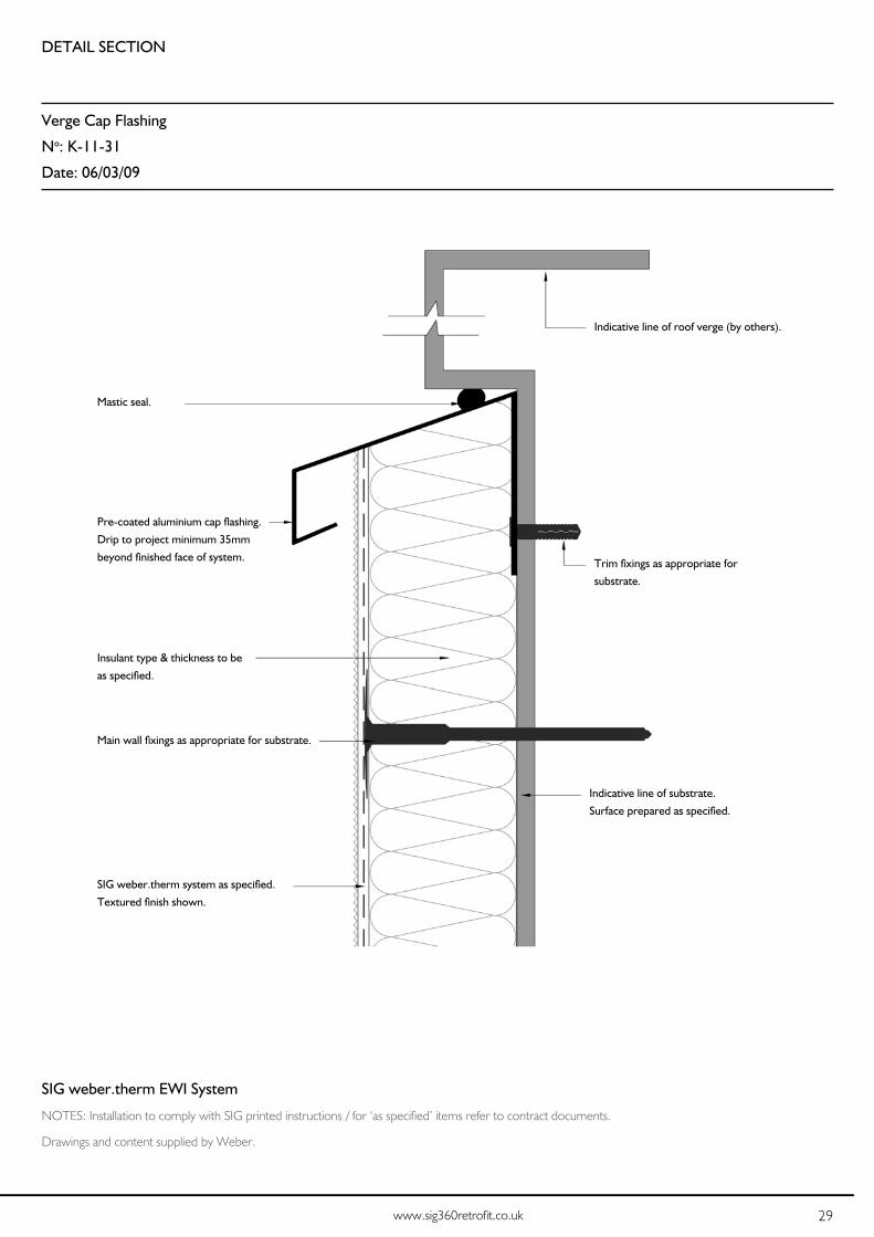
Verge Cap Flashing
No: K-11-31
Date: 06/03/09
Innovative • Creative • Technical External Wall Insulation and Render Solutions
weber.therm XMInstallation
Detail Section - Verge Cap Flashing
Typical Details
34
SIG weber.therm system as specified.
Textured finish shown.
SIG weber.therm EWI System
NOTES: Installation to comply with SIG printed instructions / for ‘as specified’ items refer to contract documents.
Drawings and content supplied by Weber.
Indicative line of roof verge (by others).
Indicative line of substrate.
Surface prepared as specified.
Trim fixings as appropriate for
substrate.
Main wall fixings as appropriate for substrate.
Insulant type & thickness to be
as specified.
Mastic seal.
Pre-coated aluminium cap flashing.
Drip to project minimum 35mm
beyond finished face of system.

30 SIG weber.therm External Wall Insulation Installation Guide
DETAIL SECTION
Ventilator
No: K-13-01
Date: 06/03/09
Innovative • Creative • Technical External Wall Insulation and Render Solutions
weber.therm XM Installation
Detail Section - Ventilator
Typical Details
35
SIG weber.therm system as specified.
Textured finish shown.
Proprietary vent of appropriate
size and material. Bedded in
SIG weber.therm Adhesive.
SIG weber.therm Adhesive
mortar.
SIG weber.therm EWI System
NOTES: Installation to comply with SIG printed instructions / for ‘as specified’ items refer to contract documents.
Drawings and content supplied by Weber.
Main wall fixings as appropriate
for substrate.
Insulant type & thickness to be
as specified.
Mastic seal around vent - specified
mastic inserted into pre-formed
check (nominal 6 x 6mm square
section) in accordance with
manufacturer’s instructions.
Indicative line of substrate.
Surface prepared as specified.
Indicative outline of vent in
substrate.
On refurbishment works existing
vent retained where possible.

31www.sig360retrofit.co.uk
DETAIL SECTION
Balanced Flue (Rectangular)
No: K-13-11 A
Date: 06/03/09
Innovative • Creative • Technical External Wall Insulation and Render Solutions
weber.therm XMInstallation
Detail Section - Balanced Flue (Rectangular)
Typical Details
36
SIG weber.therm system as specified.
Textured finish shown.
Mineral wool insulant
close butted around flue/
liner and bedded in SIG
weber.therm Adhesive if
substrate is uneven.
SIG weber.therm EWI System
NOTES: Installation to comply with SIG printed instructions / for ‘as specified’ items refer to contract documents.
Drawings and content supplied by Weber.
Insulant type & thickness to be
as specified.
Main wall fixings as appropriate
for substrate.
Indicative line of substrate.
Surface prepared as specified.
Mastic seal around flue liner
(nominal 6 x 6mm) prior to fixing
cowl / cover.
Extended flue liner.

32 SIG weber.therm External Wall Insulation Installation Guide
DETAIL SECTION
Pipe Extender Bracket
No: K-13-41 A
Date: 06/03/09
Innovative • Creative • Technical External Wall Insulation and Render Solutions
weber.therm XM Installation
Detail Plan - Pipe Extender Bracket
Typical Details
37
SIG weber.therm system as
specified. Textured finish
shown.
SIG weber.therm EWI System
NOTES: Installation to comply with SIG printed instructions / for ‘as specified’ items refer to contract documents.
Drawings and content supplied by Weber.
Insulant type & thickness to be
as specified.
Main wall fixings as appropriate
for substrate.
Indicative line of substrate.
Surface prepared as specified.
Standard Marley RT200 or similar extension back
plate, fixed to wall or timber ground by others prior
to system being applied.
Treated timber ground may be required
dependant upon insulation thickness and
extender bracket length.
Insulation thickness over timber ground
to be a minimum of 1/3 board thickness.
Clip of appropriate size and type for new /
existing pipework. All supplied and installed by
others.
Timber ground fixings (if required)
as appropriate for substrate.

33www.sig360retrofit.co.uk
DETAIL SECTION
Service Duct
No: K-13-15 A
Date: 06/03/09
Innovative • Creative • Technical External Wall Insulation and Render Solutions
weber.therm XMInstallation
Detail Section - Service Duct
Typical Details
38
SIG weber.therm system as specified.
Textured finish shown.
SIG weber.therm EWI System
NOTES: Installation to comply with SIG printed instructions / for ‘as specified’ items refer to contract documents.
Drawings and content supplied by Weber.
Main wall fixings as appropriate for substrate.
Insulant type & thickness to be
as specified.
Indicative line of substrate.
Surface prepared as specified.
Back of insulation checked to
accommodate services.
Extent of service duct to be clearly
marked to facilitate system fixings.
Services to be securely fixed
substrate prior to installation of
system.
Minimum insulation thickness over
services to be the greater of either
20mm or 1/3 board thickness.

34 SIG weber.therm External Wall Insulation Installation Guide
DETAIL SECTION
Fixing Brackets
No: K-13-61
Date: 06/03/09
Innovative • Creative • Technical External Wall Insulation and Render Solutions
weber.therm XM Installation
Detail Section - Fixing Brackets
Typical Details
39
SIG weber.therm system as
specified. Textured finish
shown.
SIG weber.therm EWI System
NOTES: Installation to comply with SIG printed instructions / for ‘as specified’ items refer to contract documents.
Drawings and content supplied by Weber.
Stand-off (nominal 5mm projection).
Appropriate bracket to support
external fitting.
Mastic seal to drilled hole.
Insulant type & thickness to be
as specified.
MASONRY SUBSTRATE
Metal tube inserted through system
to create stand-off (nominal 5mm
projection).
Appropriate bracket to support
external fitting.
Mastic seal to drilled hole and tube.
SHEATHED FRAMED SUBSTRATE
Indicative line of substrate.
Surface prepared as specified.
Fixing to suit substrate, installed in
accordance with manufacturer’s
instructions.
Indicative line of sheathing.
Indicative line stud
(lightweight steel or timber).
Self drilling / tapping screw fixing
to secure bracket to stud through
stand-off tube.

35www.sig360retrofit.co.uk
DETAIL SECTION
Insulated Reveal - Mesh Wing (Bead & Mastic)
No: P-06-06
Date: 23/02/09
Innovative • Creative • Technical External Wall Insulation and Render Solutions
weber.therm XPInstallation
Detail Plan - Insulated Reveal (Bead & Mastic)
Typical Details
20
SIG weber.therm EWI System
NOTES: Installation to comply with SIG printed instructions / for ‘as specified’ items refer to contract documents.
Drawings and content supplied by Weber.
SIG weber.therm system as specified.
Scrape texture finish shown.
Main wall fixings as appropriate
for substrate.
Indicative line of substrate.
Surface prepared as specified.
Insulant type & thickness to be
as specified.
Render only stop bead
with mastic seal.
Indicative window/glazing systems
(By Others) sealed into opening prior
to application of system.
Indicative line of cill
Reduced insulant thickness used on
reveals / heads to suit available margins.
Maximum achievable / 30mm min
recommended.
Corner bead as specified.
UPVC Profile shown.
Meshcloth lapped over bead wings.
36 SIG weber.therm External Wall Insulation Installation Guide
DETAIL SECTION
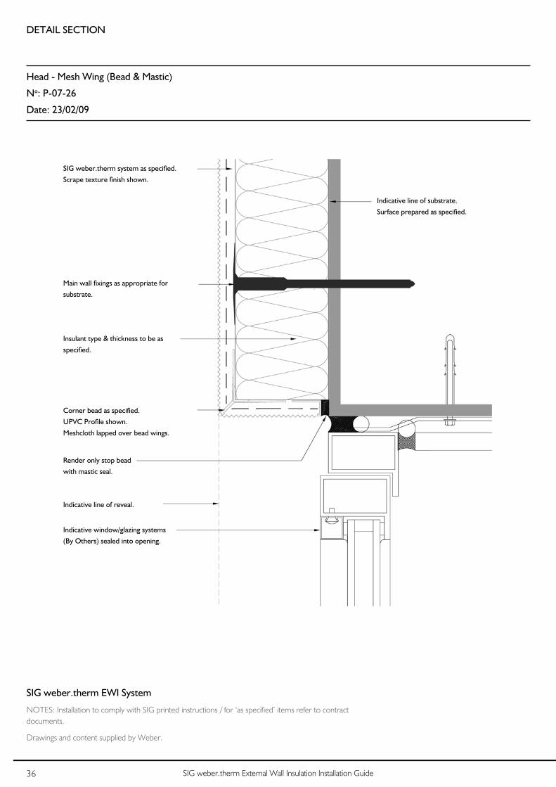
Head - Mesh Wing (Bead & Mastic)
No: P-07-26
Date: 23/02/09
Innovative • Creative • Technical External Wall Insulation and Render Solutions
weber.therm XPInstallation
Detail Section - Head (Bead & Mastic) Exposed Frame
Typical Details
22
SIG weber.therm EWI System
NOTES: Installation to comply with SIG printed instructions / for ‘as specified’ items refer to contract documents.
Drawings and content supplied by Weber.
SIG weber.therm system as specified.
Scrape texture finish shown.
Render only stop bead
with mastic seal.
Indicative line of reveal.
Corner bead as specified.
UPVC Profile shown.
Meshcloth lapped over bead wings.
Main wall fixings as appropriate for
substrate.
Indicative line of substrate.
Surface prepared as specified.
Insulant type & thickness to be as
specified.
Indicative window/glazing systems
(By Others) sealed into opening.

DETAIL SECTION
Vertical Movement Joint (Bead)
No: P-09-11
Date: 23/02/09
Innovative • Creative • Technical External Wall Insulation and Render Solutions
weber.therm XP Installation
Detail Plan - Vertical Movement Joint (Bead)
Typical Details
25
SIG weber.therm EWI System
NOTES: Installation to comply with SIG printed instructions / for ‘as specified’ items refer to contract documents.
Drawings and content supplied by Weber.
SIG weber.therm system as
specified. Scrape texture finish
shown.
Indicative line of substrate.
Surface prepared as specified.
Indicative line of movement joint in
substrate.
Main wall fixings as appropriate for
substrate.
Insulant type & thickness to be as
specified.
Meshcloth cut on either side of bead and lapped
over bead wings.
Proprietary render only movement bead
as specified.
Risband joint cut in boarding
along line of movement joint.
NOTE:Unbroken panels of render should be
limited to 45-50sq.m.
Aspect ratio to be no greater than 4:1.

38 SIG weber.therm External Wall Insulation Installation Guide
DETAIL SECTION
Compression Joint
No: P-08-11
Date: 23/02/09
Innovative • Creative • Technical External Wall Insulation and Render Solutions
weber.therm XP Installation
Detail Section - Compression Joint
Typical Details
23
SIG weber.therm EWI System
NOTES: Installation to comply with SIG printed instructions / for ‘as specified’ items refer to contract documents.
Drawings and content supplied by Weber.
SIG weber.therm system as specified.
Scrape texture finish shown.
Proprietary three-part, render only
horizontal movement joint bead (includes
render only) drip bead.
The maximum joint width which can be
protected with this profile is 15mm.
Indicative line of substrate.
Surface prepared as specified.
Main wall fixings as appropriate for
substrate.
Insulant type & thickness to be as
specified.
NOTE:Unbroken panels of render should be
limited to 45-50sq.m.
Aspect ratio to be no greater than 4:1.
Compression joint in main
structure of building.

39www.sig360retrofit.co.uk
DETAIL SECTION
Vertical Break (Bead)
No: P-09-01
Date: 23/02/09
Innovative • Creative • Technical External Wall Insulation and Render Solutions
weber.therm XPInstallation
Detail Plan - Vertical Break (Bead)
Typical Details
24
SIG weber.therm EWI System
NOTES: Installation to comply with SIG printed instructions / for ‘as specified’ items refer to contract documents.
Drawings and content supplied by Weber.
SIG weber.therm system as
specified. Scrape texture finish
shown.
Indicative line of substrate.
Surface prepared as specified.
NOTE:Unbroken panels of render should be
limited to 45-50sq.m.
Aspect ratio to be no greater than 4:1.
Proprietary render only movement bead as
specified.
Meshcloth cut on either side of bead and lapped
over bead wings.
Main wall fixings as appropriate for
substrate.
Insulant type & thickness to be as
specified.

40 SIG weber.therm External Wall Insulation Installation Guide
Guidance & Advice for Maintaining External Wall InsulationThe application of External Wall Insulation to your home has been completed and the change in appearance and warmth is amazing, so what do you have to do to keep it looking great and performing to the highest standard? SIG weber.therm External Wall Insulation is traditionally maintenance free but to ensure the optimum life, aesthetics and thermal efficiency, please follow the guidelines detailed below...
Fixing items to your walls
If after the work has been completed you decide to add items such as satellite dishes, gate posts, hanging baskets etc. to the outside of your property you should ensure that the correct fixings are applied and are long enough to pass through to the original wall.
• Care should be taken so as not to compress the system as this could be detrimental to the performance and the security of the item being fixed. Fixtures must be anchored back to the original wall and not the External Wall Insulation system.
• Percussion drilling must not be used as there is a risk of snagging the mesh layer but this can be minimised by the use of diamond tipped drill bit.
• Mastic sealant should be used to prevent water entering the system around any fixings.
• Tradesman should obtain relevant information from the Housing Association (if applicable) prior to commencing installation of any fixture.
Innovative • Creative • Technical External Wall Insulation and Render Solutions
weber.therm XMInstallation
42
Guidance & Advice for MaintainingExternal Wall Insulation The application of External Wall Insulation to your home has been completed and the change in appearance and warmth is amazing, so what do you have to do to keep it looking great and performing to the highest standard? Weber External Wall Insulation is traditionallymaintenance free but to ensure the optimum life, aesthetics and thermal efficiency, please follow the guidelines detailed below...
Fixing items to your walls If after the work has been completed you decide to add items such as satellite dishes, gate posts, hanging baskets etc. to the outside of your property you should ensure that the correct fixings are applied and are long enough to pass through to the original wall. Care should be taken so as not to compress the
system as this could be detrimental to the performance and the security of the item being fixed. Fixtures must be anchored back to the original wall and not the External Wall Insulation system.
Percussion drilling must not be used as there is a risk of snagging the mesh layer but this can be minimised by the use of diamond tipped drill bit.
Mastic sealant should be used to prevent water entering the system around any fixings.
Tradesman should obtain relevant information from the Housing Association (if applicable) prior to commencing installation of any fixture .
Maintenance
Guarantees apply to the durability of the system over the term of the guarantee but not the appearance of the finish, which may require occasional maintenance to restore its appearance, usually after 15 years in normal climatic conditions.
Guarantees apply to the durability of the system over the term of the guarantee but not the appearance of the finish, which may require occasional maintenance to restore its appearance, usually after 15 years in normal climatic conditions.
Innovative • Creative • Technical External Wall Insulation and Render Solutions
weber.therm XMInstallation
42
Guidance & Advice for MaintainingExternal Wall Insulation The application of External Wall Insulation to your home has been completed and the change in appearance and warmth is amazing, so what do you have to do to keep it looking great and performing to the highest standard? Weber External Wall Insulation is traditionallymaintenance free but to ensure the optimum life, aesthetics and thermal efficiency, please follow the guidelines detailed below...
Fixing items to your walls If after the work has been completed you decide to add items such as satellite dishes, gate posts, hanging baskets etc. to the outside of your property you should ensure that the correct fixings are applied and are long enough to pass through to the original wall. Care should be taken so as not to compress the
system as this could be detrimental to the performance and the security of the item being fixed. Fixtures must be anchored back to the original wall and not the External Wall Insulation system.
Percussion drilling must not be used as there is a risk of snagging the mesh layer but this can be minimised by the use of diamond tipped drill bit.
Mastic sealant should be used to prevent water entering the system around any fixings.
Tradesman should obtain relevant information from the Housing Association (if applicable) prior to commencing installation of any fixture .
Maintenance
Guarantees apply to the durability of the system over the term of the guarantee but not the appearance of the finish, which may require occasional maintenance to restore its appearance, usually after 15 years in normal climatic conditions.

41www.sig360retrofit.co.uk
Use of Ladders
All rendered wall surfaces can be permanently damaged by the careless use of ladders. Even ladders with protected ends can remove aggregate or mark the surface.
To avoid problems…
• Spread the load on the surface with a batten.
• Wrap the batten in cloth or sponge.
• Do not drag the ladder over the surface when moving.
Innovative • Creative • Technical External Wall Insulation and Render Solutions
weber.therm XM Installation
43
Use of Ladders All rendered wall surfaces can be permanently damaged by the careless use of ladders. Even ladders with protected ends can remove aggregate or mark the surface. To avoid problems…
Spread the load on the surface with a batten.
Wrap the batten in cloth or sponge. Do not drag the ladder over the
surface when moving.
CleaningNormal dirt on the surface of an external rendered wall is generally accepted as part of the normal weathering process. However, if surfaces do require cleaning or removal of algae please follow the instructions below. weber CL150 is an easy to use, water-based masonry wash containing carefully selected biocides to clean and sterilise substrates.
1. Drench the affected area with undiluted weber CL150 using a brush or a sprayer.
2. Leave the area for 48 hours to ensure weber CL150 has killed all the algae.
3. Wash the area using a pressurised washer set to low pressure with a fanned water jet taking care of exposed edges.
Once complete the substrate will be free from dirt, grime & algae and will be protected for a considerable period of time. It may be necessary to repeat this process every few years in areas of high algae spores to maintain the best aesthetics.
48 Hours
Rendered Surface
Cloth or Sponge
Batten
Ladder
Maintenance
Cleaning
Normal dirt on the surface of an external rendered wall is generally accepted as part of the normal weathering process. However, if surfaces do require cleaning or removal of algae please follow the instructions below. weber CL150 is an easy to use, water-based masonry wash containing carefully selected biocides to clean and sterilise substrates.
1. Drench the affected area with undiluted weber CL150 using a brush or a sprayer.
2. Leave the area for 48 hours to ensure weber CL150 has killed all the algae.
3. Wash the area using a pressurised washer set to low pressure with a fanned water jet taking care of exposed edges.
Once complete the substrate will be free from dirt, grime & algae and will be protected for a considerable period of time. It may be necessary to repeat this process every few years in areas of high algae spores to maintain the best aesthetics.
Innovative • Creative • Technical External Wall Insulation and Render Solutions
weber.therm XM Installation
43
Use of Ladders All rendered wall surfaces can be permanently damaged by the careless use of ladders. Even ladders with protected ends can remove aggregate or mark the surface. To avoid problems…
Spread the load on the surface with a batten.
Wrap the batten in cloth or sponge. Do not drag the ladder over the
surface when moving.
CleaningNormal dirt on the surface of an external rendered wall is generally accepted as part of the normal weathering process. However, if surfaces do require cleaning or removal of algae please follow the instructions below. weber CL150 is an easy to use, water-based masonry wash containing carefully selected biocides to clean and sterilise substrates.
1. Drench the affected area with undiluted weber CL150 using a brush or a sprayer.
2. Leave the area for 48 hours to ensure weber CL150 has killed all the algae.
3. Wash the area using a pressurised washer set to low pressure with a fanned water jet taking care of exposed edges.
Once complete the substrate will be free from dirt, grime & algae and will be protected for a considerable period of time. It may be necessary to repeat this process every few years in areas of high algae spores to maintain the best aesthetics.
48 Hours
Rendered Surface
Cloth or Sponge
Batten
Ladder
Maintenance
Web: www.sig360retrofit.co.uk
Tel: 0844 5766 762
Ref: Version 1 - Sept 2013ID - 126
Designed and manufactured by Saint-Gobain Weber Limited for SIG.
Photography and copy contributed by Weber.
Email: [email protected]