installation instruction air cooled air … · power and duct connections are required at the point...
TRANSCRIPT

CONTENTS
INSTALLATION SAFETY INFORMATION . . . . . . . . 3
GENERAL . . . . . . . . . . . . . . . . . . . . . . . . . . . . . . . . . 3
INSPECTION . . . . . . . . . . . . . . . . . . . . . . . . . . . . . . . 3
MAINTENANCE AND RENEWAL PARTS . . . . . . . . 3
APPROVALS . . . . . . . . . . . . . . . . . . . . . . . . . . . . . . 3
INSTALLATION . . . . . . . . . . . . . . . . . . . . . . . . . . . . 4
SEQUENCE OF OPERATION . . . . . . . . . . . . . . . . 14
START-UP . . . . . . . . . . . . . . . . . . . . . . . . . . . . . . . 14
TROUBLE SHOOTING . . . . . . . . . . . . . . . . . . . . . . 18
TYPICAL WIRING DIAGRAM NOTES . . . . . . . . . . 22
INSTALLATIONINSTRUCTION
SAVE THIS MANUAL
CHAMPION®PLUS
SINGLE PACKAGED GAS/ELECTRIC
AIR COOLED AIR CONDITIONERS
3 AND 4 NOMINAL TON
035-18579-000-A-0302
DNP: 036048
��035-18579-000-A-0302
2 Unitary Products Group
TABLE OF CONTENTS
INSTALLATION SAFETY INFORMATION . . . . . . . . 3
GENERAL . . . . . . . . . . . . . . . . . . . . . . . . . . . . . . . . . 3
INSPECTION . . . . . . . . . . . . . . . . . . . . . . . . . . . . . . . 3
MAINTENANCE AND RENEWAL PARTS . . . . . . . . 3
APPROVALS . . . . . . . . . . . . . . . . . . . . . . . . . . . . . . 3
INSTALLATION . . . . . . . . . . . . . . . . . . . . . . . . . . . . 4LIMITATIONS . . . . . . . . . . . . . . . . . . . . . . . . . . . . . . . . . . 4LOCATION . . . . . . . . . . . . . . . . . . . . . . . . . . . . . . . . . . . . 4CLEARANCES . . . . . . . . . . . . . . . . . . . . . . . . . . . . . . . . . 5RIGGING OR HANDLING . . . . . . . . . . . . . . . . . . . . . . . . . 5DUCT WORK . . . . . . . . . . . . . . . . . . . . . . . . . . . . . . . . . . 5ROOF CURB . . . . . . . . . . . . . . . . . . . . . . . . . . . . . . . . . . . 6FILTERS . . . . . . . . . . . . . . . . . . . . . . . . . . . . . . . . . . . . . . 6CONDENSATE DRAIN . . . . . . . . . . . . . . . . . . . . . . . . . . . 6SERVICE ACCESS . . . . . . . . . . . . . . . . . . . . . . . . . . . . . . 6THERMOSTAT . . . . . . . . . . . . . . . . . . . . . . . . . . . . . . . . . 6POWER AND CONTROL WIRING . . . . . . . . . . . . . . . . . . 6COMPRESSORS . . . . . . . . . . . . . . . . . . . . . . . . . . . . . . . 7GAS PIPING . . . . . . . . . . . . . . . . . . . . . . . . . . . . . . . . . . . 9GAS CONNECTION . . . . . . . . . . . . . . . . . . . . . . . . . . . . . 9FLUE VENT HOOD . . . . . . . . . . . . . . . . . . . . . . . . . . . . . 10
SEQUENCE OF OPERATION . . . . . . . . . . . . . . . . 14HEATING . . . . . . . . . . . . . . . . . . . . . . . . . . . . . . . . . . . . 14COOLING . . . . . . . . . . . . . . . . . . . . . . . . . . . . . . . . . . . . 14CIRCULATING FAN . . . . . . . . . . . . . . . . . . . . . . . . . . . . 14
START-UP . . . . . . . . . . . . . . . . . . . . . . . . . . . . . . . 14PRE-START CHECK LIST . . . . . . . . . . . . . . . . . . . . . . . 14OPERATING INSTRUCTIONS . . . . . . . . . . . . . . . . . . . . 14TO TURN OFF GAS TO UNIT . . . . . . . . . . . . . . . . . . . . 15POST-START CHECK LIST (GAS) . . . . . . . . . . . . . . . . 15MANIFOLD GAS PRESSURE ADJUSTMENT . . . . . . . . 15BURNER INSTRUCTIONS . . . . . . . . . . . . . . . . . . . . . . . 15HOT SURFACE PILOT INSTRUCTIONS . . . . . . . . . . . . 15ADJUSTMENT OF TEMPERATURE RISE . . . . . . . . . . 16
DIRECT DRIVE BLOWER . . . . . . . . . . . . . . . . . . . . . . . . . . . . 16
CHECKING GAS INPUT . . . . . . . . . . . . . . . . . . . . . . . . 16NATURAL GAS . . . . . . . . . . . . . . . . . . . . . . . . . . . . . . . . . . . 16
TROUBLE SHOOTING . . . . . . . . . . . . . . . . . . . . . . 18
TYPICAL WIRING DIAGRAM NOTES . . . . . . . . . 22
LIST OF FIGURES
1 PRODUCT NOMENCLATURE . . . . . . . . . . . . . . . . . . 42 UNIT CENTER OF GRAVITY . . . . . . . . . . . . . . . . . . . 53 FIELD WIRING DIAGRAM CONTROL WIRING . . . . . 74 POWER WIRING FIELD DIAGRAM . . . . . . . . . . . . . . 75 EXT SUPPLY CONN EXT SHUT-OFF . . . . . . . . . . . . 96 FLUE VENT OUTLET AIR HOOD . . . . . . . . . . . . . . . 107 UNIT DIMENSIONS - FRONT . . . . . . . . . . . . . . . . . . 128 UNIT DIMENSIONS - FRONT & BOTTOM . . . . . . . . 139 UNIT DIMENSIONS - BACK & BOTTOM . . . . . . . . . 1310 GAS VALVE - FRONT . . . . . . . . . . . . . . . . . . . . . . . . 1511 GAS VALVE - REAR . . . . . . . . . . . . . . . . . . . . . . . . . 1512 PROPER FLAME ADJUSTMENT . . . . . . . . . . . . . . . 1513 IGNITOR AND FLAME SENSOR ASSEMBLY . . . . . 1614 TYP WIRING DIA (208/230-1-60 PS) . . . . . . . . . . . . 1915 TYP WIRING DIA (208/230-3-60 PS) . . . . . . . . . . . . 2016 TYP WIRING DIA (460-3-60 PS) . . . . . . . . . . . . . . . . 2117 TYPICAL WIRING DIAGRAM LEDGEND . . . . . . . . . 22
LIST OF TABLES
1 UNIT APPLICATION DATA . . . . . . . . . . . . . . . . . . . . . . 42 UNIT WEIGHTS AND CENTER OF GRAVITY . . . . . . . 53 NATURAL GAS APPLICATION DATA . . . . . . . . . . . . . 84 PROPANE (LP) GAS APPLICATION DATA . . . . . . . . . 85 NATURAL GAS PIPE SIZING CHART . . . . . . . . . . . . . 96 PROPANE (LP) GAS PIPE SIZING CHART . . . . . . . . . 97 PHYSICAL DATA . . . . . . . . . . . . . . . . . . . . . . . . . . . . 118 ELECTRICAL DATA . . . . . . . . . . . . . . . . . . . . . . . . . . 119 UNIT DIMENSIONS FRONT . . . . . . . . . . . . . . . . . . . . 1210 UNIT MINIMUM CLEARANCES . . . . . . . . . . . . . . . . . 1211 GASE RATE - CUBIC FEET PER HOUR . . . . . . . . . . 17
035-18579-000-A-0302
Unitary Products Group 3
��
INSTALLATION SAFETY INFORMATION
Read these instructions before continuing this applianceinstallation. This is an outdoor combination heating and cool-ing equipment. The installer must assure that these instruc-tions are made available to the consumer and withinstructions to retain them for future reference.
1. Refer to the furnace rating plate for the approved type ofgas for this furnace.
2. Install this furnace only in a location and position asspecified on pages 4 and 5 of these instructions.
3. Never test for gas leaks with an open flame. Use com-mercially available soap solution made specifically forthe detection of leaks when checking all connections, asspecified on pages 3 and 10 of these instructions.
4. Always install furnace to operate within the furnace’sintended temperature-rise range with the duct systemand within the allowable external static pressure range,as specified on the unit name/rating plate, specified onpages 8 and 16 of these instructions.
5. This equipment is not to be used for temporary heatingof buildings or structures under construction.
GENERAL
YORK Model D1NP units are cooling/heating air conditionersdesigned for outdoor installation. Only gas piping, electricpower and duct connections are required at the point ofinstallation.
The gas-fired heaters have hot surface to pilot ignition. Thetubular heat exchangers are aluminized steel.
Installer should pay particular attention to the words; NOTE,CAUTION, and WARNING. NOTES are intended to clarify ormake the installation easier. CAUTIONS are given to preventequipment damage. WARNINGS are given to alert the instal-
ler that personal injury and/or equipment damage may resultif installation procedure is not handled properly.
INSPECTION
As soon as a unit is received, it should be inspected for possi-ble damage during transit. If damage is evident, the extent ofthe damage should be noted on the carrier's freight bill. Aseparate request for inspection by the carrier's agent shouldbe made in writing. Refer to Form 50.15-NM for additionalinformation.
MAINTENANCE AND RENEWAL PARTS
Refer to User’s, Maintenance and Service Information Man-ual, Part No. 035-15509-001.
APPROVALS
Design certified by CGA and AGA listed as follows:
1. For use as a forced air furnace with cooling unit.
2. For outdoor installation only.
3. For installation directly on combustible flooring or, inU.S., on wood flooring or Class A; B; C roof coveringmaterial.
4. For installation on combustible material.
5. For use with natural gas and/or propane (LP) gas.
Not suitable for use with conventional venting systems.
FIRE OR EXPLOSION HAZARD
FAILURE TO FOLLOW THE SAFETY WARN-INGS EXACTLY COULD RESULT IN SERIOUSINJURY, DEATH OR PROPERTY DAMAGE.
NEVER TEST FOR GAS LEAKS WITH AN OPENFLAME. USE A COMMERCIALLY AVAILABLESOAP SOLUTION MADE SPECIFICALLY FORTHE DETECTION OF LEAKS TO CHECK ALLCONNECTIONS. A FIRE OR EXPLOSION MAYRESULT CAUSING PROPERTY DAMAGE, PER-SONAL INJURY OR LOSS OF LIFE.
THIS PRODUCT MUST BE INSTALLED INSTRICT COMPLIANCE WITH THE ENCLOSEDINSTALLATION INSTRUCTIONS AND ANYAPPLICABLE LOCAL, STATE, AND NATIONALCODES INCLUDING BUT NOT LIMITED TO,BUILDING, ELECTRICAL AND MECHANICALCODES.
IMPROPER INSTALLATION MAY CREATE ACONDITION WHERE THE OPERATION OF THEPRODUCT COULD CAUSE PERSONAL INJURYOR PROPERTY DAMAGE.
��035-18579-000-A-0302
4 Unitary Products Group
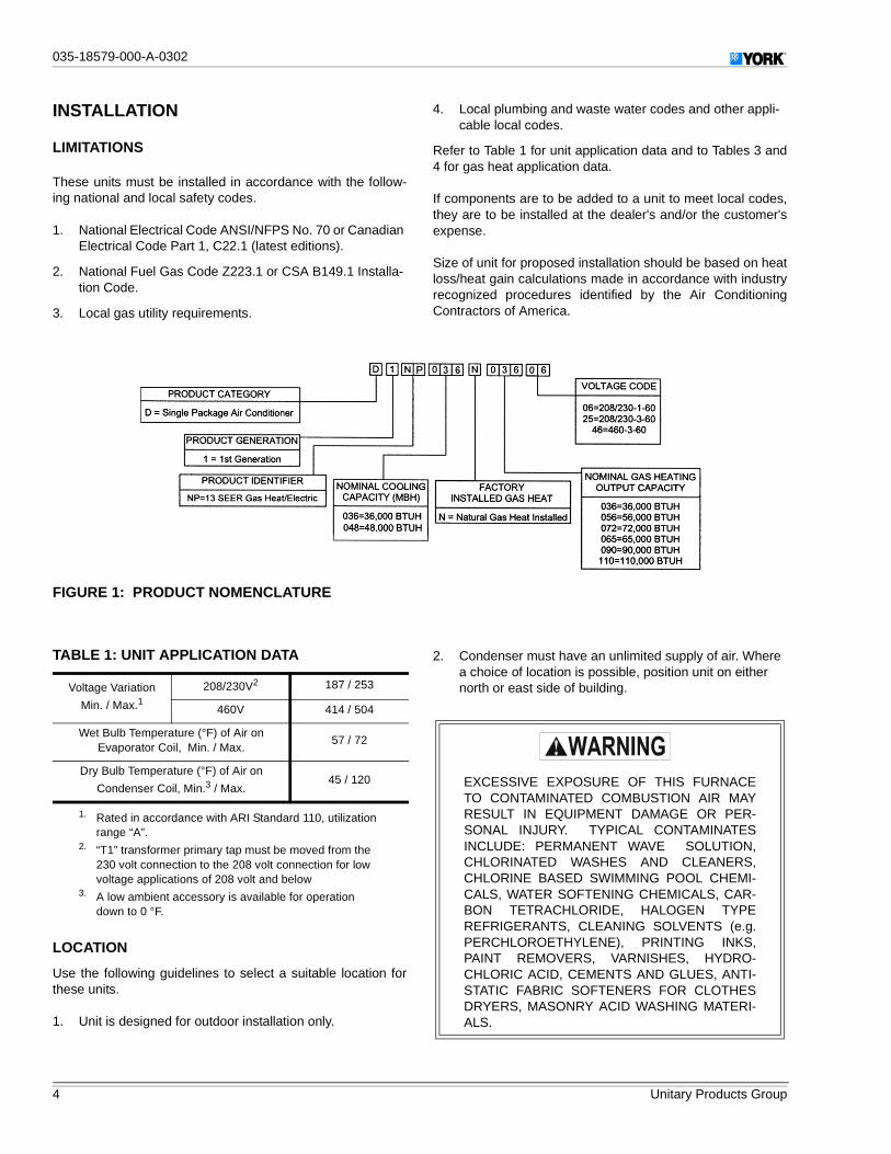
INSTALLATION
LIMITATIONS
These units must be installed in accordance with the follow-ing national and local safety codes.
1. National Electrical Code ANSI/NFPS No. 70 or CanadianElectrical Code Part 1, C22.1 (latest editions).
2. National Fuel Gas Code Z223.1 or CSA B149.1 Installa-tion Code.
3. Local gas utility requirements.
4. Local plumbing and waste water codes and other appli-cable local codes.
Refer to Table 1 for unit application data and to Tables 3 and4 for gas heat application data.
If components are to be added to a unit to meet local codes,they are to be installed at the dealer's and/or the customer'sexpense.
Size of unit for proposed installation should be based on heatloss/heat gain calculations made in accordance with industryrecognized procedures identified by the Air ConditioningContractors of America.
LOCATION
Use the following guidelines to select a suitable location forthese units.
1. Unit is designed for outdoor installation only.
2. Condenser must have an unlimited supply of air. Wherea choice of location is possible, position unit on eithernorth or east side of building.
FIGURE 1: PRODUCT NOMENCLATURE
TABLE 1: UNIT APPLICATION DATA
Voltage Variation
Min. / Max.1
1. Rated in accordance with ARI Standard 110, utilizationrange “A”.
208/230V2
2. “T1” transformer primary tap must be moved from the230 volt connection to the 208 volt connection for lowvoltage applications of 208 volt and below
187 / 253
460V 414 / 504
Wet Bulb Temperature (°F) of Air onEvaporator Coil, Min. / Max.
57 / 72
Dry Bulb Temperature (°F) of Air on
Condenser Coil, Min.3 / Max.
3. A low ambient accessory is available for operationdown to 0 °F.
45 / 120 EXCESSIVE EXPOSURE OF THIS FURNACETO CONTAMINATED COMBUSTION AIR MAYRESULT IN EQUIPMENT DAMAGE OR PER-SONAL INJURY. TYPICAL CONTAMINATESINCLUDE: PERMANENT WAVE SOLUTION,CHLORINATED WASHES AND CLEANERS,CHLORINE BASED SWIMMING POOL CHEMI-CALS, WATER SOFTENING CHEMICALS, CAR-BON TETRACHLORIDE, HALOGEN TYPEREFRIGERANTS, CLEANING SOLVENTS (e.g.PERCHLOROETHYLENE), PRINTING INKS,PAINT REMOVERS, VARNISHES, HYDRO-CHLORIC ACID, CEMENTS AND GLUES, ANTI-STATIC FABRIC SOFTENERS FOR CLOTHESDRYERS, MASONRY ACID WASHING MATERI-ALS.

035-18579-000-A-0302
Unitary Products Group 5
��
3. For ground level installation, a level pad or slab shouldbe used. The thickness and size of the pad or slab usedshould meet local codes and unit weight. Do not tie theslab to the building foundation.
4. For roof top installation, be sure the structure will supportthe weight of the unit plus any field installed components.Unit must be installed on a level roof curb or appropriateangle iron frame providing adequate support under thecompressor/condenser section.
5. Maintain level tolerance of unit to 1/8" maximum.
CLEARANCES
All units require certain clearances for proper operation andservice. Refer to Table 10 for the clearances required forcombustion, construction, servicing and proper unit opera-tion.
RIGGING OR HANDLING
Care must be exercised when moving the unit. Do notremove any packaging until the unit is near the place ofinstallation. Rig unit with slings placed under the unit.Spreader bars of sufficient length should be used across thetop of the unit.
Units may also be moved or lifted with a fork-lift. Slottedopenings in the skid are provided for this purpose. Forksmust pass completely through the base.
Refer to Table 2 for unit weights and to Figure 2 for approxi-mate center of gravity.
DUCT WORK
These units are adaptable to downflow use as well as rearsupply and return air duct openings. To convert to downflow,use the following steps:
1. Remove the duct covers found in the bottom return andsupply air duct openings. There are four (4) screwssecuring each duct cover (save these screws to uselater).
2. Install the duct covers, removed in step one, to the rearsupply and return air duct openings. Secure with the four(4) screws used in step one.
DO NOT PERMIT OVERHANGING STRUC-TURES OR SHRUBS TO OBSTRUCT THE CON-DENSER AIR DISCHARGE, COMBUSTION AIRINLET OR VENT OUTLET.
BEFORE LIFTING A UNIT, MAKE SURE THATITS WEIGHT IS DISTRIBUTED EQUALLY ONTHE CABLES SO THAT IT WILL LIFT EVENLY.
TABLE 2: UNIT WEIGHTS AND CENTER OFGRAVITY
UNITSIZE
SHIPPINGWEIGHT
(LBS.)
OPERATINGWEIGHT
(LBS.)
CORNER WEIGHTS(LOCATION, LBS.)
“A” “B” “C” “D”
036 400 395 100 96 98 101
048 475 470 133 130 102 104
FIGURE 2: UNIT CENTER OF GRAVITY
"A"
"B"
"C"
"D"
49 1/825 25
47 1/4
FRONT
OF
UNIT
CENTER OF
GRAVITY

��035-18579-000-A-0302
6 Unitary Products Group
Duct work should be designed and sized according to themethods of the Air Conditioning Contractors of America(ACCA), as set forth in their Manual D.
A closed return duct system shall be used. This shall not pre-clude use of economizers or ventilation air intake. Flexiblejoints may be used in the supply and return duct work to min-imize the transmission of noise.
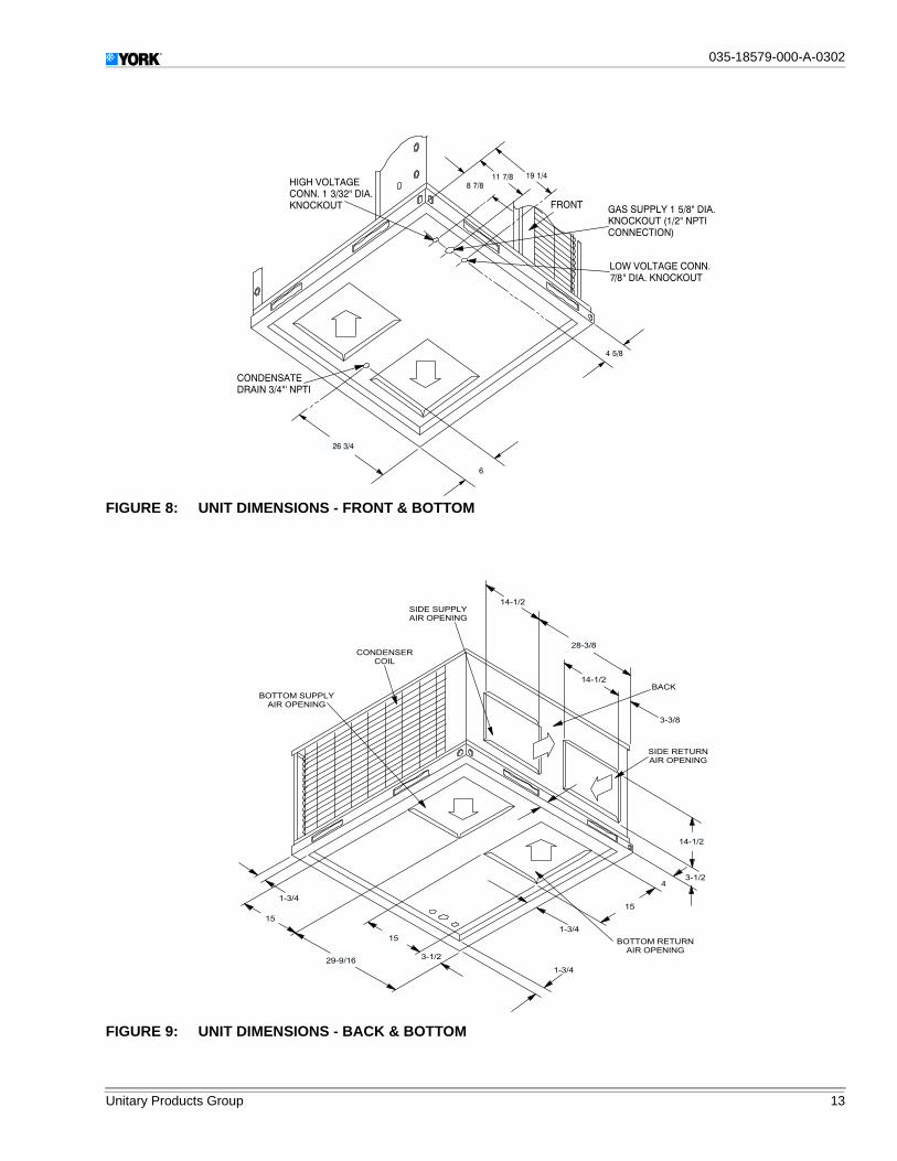
NOTE: Be sure to note supply and return openings.
Refer to Figure 8 and 9 for information concerning rear andbottom supply and return air duct openings.
ROOF CURB
On applications when a roof curb is used, the unit must bepositioned on the curb so the front of the unit is tight againstthe curb.
FILTERS
Single phase units are shipped without a filter or filter racksand is the responsibility of the installer to secure a filter in thereturn air ductwork or install a Filter/Frame Kit (1FF0110).
A filter rack and a high velocity filters are standard on threephase units.
Filters must always be used and must be kept clean. Whenfilters become dirt laden, insufficient air will be delivered bythe blower, decreasing your units efficiency and increasingoperating costs and wear-and-tear on the unit and controls.
Filters should be checked monthly especially since this unit isused for both heating and cooling.
CONDENSATE DRAIN
A condensate trap is recommended to be installed in the con-densate drain. The plumbing must conform to local codes.
Use a sealing compound on male pipe threads. Install thecondensate drain line (NPTF) to spill into an open drain.
SERVICE ACCESS
Access to all serviceable components is provided by the fol-lowing removable panels:
• Blower compartment• Gas control/electrical service access
Refer to Figure 7 for location of these access panels and min-imum clearances in Table 10.
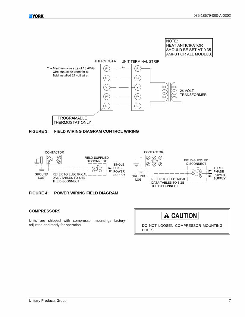
THERMOSTAT
The room thermostat should be located on an inside wallapproximately 56" above the floor where it will not be subjectto drafts, sun exposure or heat from electrical fixtures orappliances. Follow manufacturer's instructions enclosed withthe thermostat for general installation procedure. Four colorcoded insulated wires (minimum #18 AWG) should be usedto connect thermostat to unit. See Figure 3.
POWER AND CONTROL WIRING
Field wiring to the unit must conform to provisions of the cur-rent N.E.C. ANSI/NFPA No. 70 or C.E.C. and/or local ordi-nances. The unit must be electrically grounded in accordancewith local codes or, in their absence, with the N.E.C./C.E.C.Voltage tolerances which must be maintained at the com-pressor terminals during starting and running conditions areindicated on the unit Rating Plate and Table 8.
The wiring entering the cabinet must be provided withmechanical strain relief.
A fused disconnect switch should be field provided for theunit. If any of the wire supplied with the unit must be replaced,replacement wire must be of the type shown on the wiringdiagram.
Electrical line must be sized properly to carry the load. Eachunit must be wired with a separate branch circuit fed directlyfrom the meter panel and properly fused.
Refer to Figure 4 for typical field wiring and to the appropriateunit wiring diagram for control circuit and power wiring infor-mation.
WHEN FASTENING DUCT WORK TO THE SIDEDUCT FLANGES ON THE UNIT, INSERT THESCREWS THROUGH THE DUCT FLANGESONLY. DO NOT INSERT THE SCREWSTHROUGH THE CASING. OUTDOOR DUCT-WORK MUST BE INSULATED AND WATER-PROOFED.
035-18579-000-A-0302
Unitary Products Group 7
��
COMPRESSORS
Units are shipped with compressor mountings factory-adjusted and ready for operation.
FIGURE 3: FIELD WIRING DIAGRAM CONTROL WIRING
�
�
�
�
�
�
��
�
�
� � � � � � � � �
� � � � � � � � � � �
� �� � � � � � � � � � � � � � � � � � � � � � � � � � � � � �
� � � � � � � � � � � � ! � � " # � $ � � � � � # � � � � � % " "
� � � � � � � � � " # � � � � & % " " � # � ' ( � ) � " & � � � � � *
� � � � � � + � , � � � , � � � � � � , �
� � � -
� � � � � � , � , � � � �
� � � + � . � � � � � � � � / * 0 1
� � � � 2 � � � � � � � � . � � � *
' ( � 3 � �
� � � � 2 � � � �
FIGURE 4: POWER WIRING FIELD DIAGRAM
� � � � � �
� � �
� � � � � � � � � � � � � � �
� � � � � � � � � � � � � � �
� � � � � � � � � � � �
� � � � � � � � � � �
� � � � � � � � �
� � � � � � � � �
� � � � � � � � � � �
� � � � � � � � �
� � � � � � � � �
� � � � � �
� � � � � � � � � � � � � � � � � �
� � � � � � � � � � � � � � �
� � � � � � � � � � � �
� � � � �
� � � � �
� � � � �
� � � � � �
� � � � �
� � � � �
� � � � �
� � � � � �
DO NOT LOOSEN COMPRESSOR MOUNTINGBOLTS.
��035-18579-000-A-0302
8 Unitary Products Group
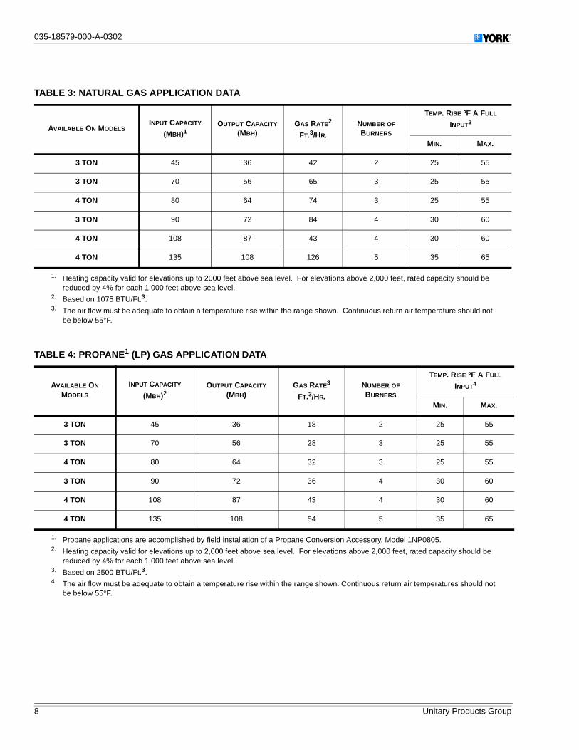
TABLE 3: NATURAL GAS APPLICATION DATA
AVAILABLE ON MODELSINPUT CAPACITY
(MBH)1OUTPUT CAPACITY
(MBH)GAS RATE2
FT.3/HR.
NUMBER OF
BURNERS
TEMP. RISE ºF A FULL
INPUT3
MIN. MAX.
3 TON 45 36 42 2 25 55
3 TON 70 56 65 3 25 55
4 TON 80 64 74 3 25 55
3 TON 90 72 84 4 30 60
4 TON 108 87 43 4 30 60
4 TON 135 108 126 5 35 65
1. Heating capacity valid for elevations up to 2000 feet above sea level. For elevations above 2,000 feet, rated capacity should bereduced by 4% for each 1,000 feet above sea level.
2. Based on 1075 BTU/Ft.3.3. The air flow must be adequate to obtain a temperature rise within the range shown. Continuous return air temperature should not
be below 55°F.
TABLE 4: PROPANE1 (LP) GAS APPLICATION DATA
AVAILABLE ON
MODELS
INPUT CAPACITY
(MBH)2OUTPUT CAPACITY
(MBH)GAS RATE3
FT.3/HR.
NUMBER OF
BURNERS
TEMP. RISE ºF A FULL
INPUT4
MIN. MAX.
3 TON 45 36 18 2 25 55
3 TON 70 56 28 3 25 55
4 TON 80 64 32 3 25 55
3 TON 90 72 36 4 30 60
4 TON 108 87 43 4 30 60
4 TON 135 108 54 5 35 65
1. Propane applications are accomplished by field installation of a Propane Conversion Accessory, Model 1NP0805.2. Heating capacity valid for elevations up to 2,000 feet above sea level. For elevations above 2,000 feet, rated capacity should be
reduced by 4% for each 1,000 feet above sea level.3. Based on 2500 BTU/Ft.3.4. The air flow must be adequate to obtain a temperature rise within the range shown. Continuous return air temperatures should not
be below 55°F.
035-18579-000-A-0302
Unitary Products Group 9
��
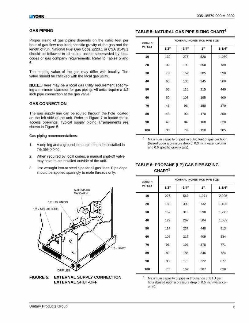
GAS PIPING
Proper sizing of gas piping depends on the cubic feet perhour of gas flow required, specific gravity of the gas and thelength of run. National Fuel Gas Code Z223.1 or CSA B149.1should be followed in all cases unless superseded by localcodes or gas company requirements. Refer to Tables 5 and6.
The heating value of the gas may differ with locality. Thevalue should be checked with the local gas utility.
NOTE: There may be a local gas utility requirement specify-ing a minimum diameter for gas piping. All units require a 1/2inch pipe connection at the gas valve.
GAS CONNECTION
The gas supply line can be routed through the hole locatedon the left side of the unit. Refer to Figure 7 to locate theseaccess openings. Typical supply piping arrangements areshown in Figure 5.
Gas piping recommendations:
1. A drip leg and a ground joint union must be installed inthe gas piping.
2. When required by local codes, a manual shut-off valvemay have to be installed outside of the unit.
3. Use wrought iron or steel pipe for all gas lines. Pipe dopeshould be applied sparingly to male threads only.
FIGURE 5: EXTERNAL SUPPLY CONNECTIONEXTERNAL SHUT-OFF
� � � � � � � � � � � � � � �
� � � � � � � � � � � �
� � � � � � �
� � � � � � � � �
� � � � � � � �
� � � � � � � � � �
TABLE 5: NATURAL GAS PIPE SIZING CHART1
LENGTH
IN FEET
NOMINAL INCHES IRON PIPE SIZE
1/2” 3/4” 1” 1-1/4”
10 132 278 520 1,050
20 92 190 350 730
30 73 152 285 590
40 63 130 245 500
50 56 115 215 440
60 50 105 195 400
70 46 96 180 370
80 43 90 170 350
90 40 84 160 320
100 38 79 150 305
1. Maximum capacity of pipe in cubic feet of gas per hour(based upon a pressure drop of 0.3 inch water columnand 0.6 specific gravity gas).
TABLE 6: PROPANE (LP) GAS PIPE SIZINGCHART1
1. Maximum capacity of pipe in thousands of BTU perhour (based upon a pressure drop of 0.5 inch water col-umn).
LENGTH
IN FEET
NOMINAL INCHES IRON PIPE SIZE
1/2” 3/4” 1” 1-1/4”
10 275 567 1,071 2,205
20 189 393 732 1,496
30 152 315 590 1,212
40 129 267 504 1,039
50 114 237 448 913
60 103 217 409 834
70 96 196 378 771
80 89 185 346 724
90 83 173 322 677
100 78 162 307 630
��035-18579-000-A-0302
10 Unitary Products Group
4. All piping should be cleaned of dirt and scale by ham-mering on the outside of the pipe and blowing out theloose dirt and scale. Before initial start-up, be sure thatall of the gas lines external to the unit have been purgedof air.
5. The gas supply should be a separate line and installed inaccordance with all safety codes as prescribed underLimitations. After the gas connections have been com-pleted, open the main shut-off valve admitting normalgas pressure to the mains. Check all joints for leaks withsoap solution or other material suitable for the purpose.NEVER USE A FLAME.
6. The furnace must be isolated from the gas supply pipingsystem by closing its individual manual shut-off valveduring any pressure testing of the gas supply piping sys-tem at test pressures equal to or less than 1/2 psig (3.48kPa).
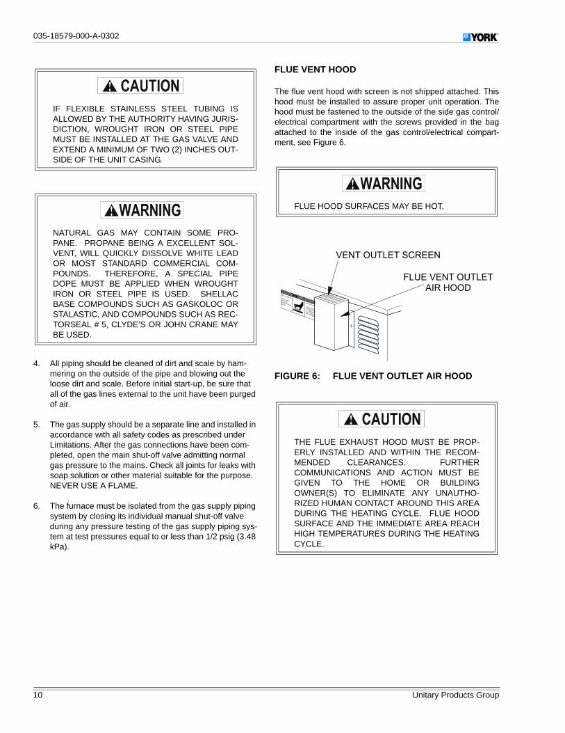
FLUE VENT HOOD
The flue vent hood with screen is not shipped attached. Thishood must be installed to assure proper unit operation. Thehood must be fastened to the outside of the side gas control/electrical compartment with the screws provided in the bagattached to the inside of the gas control/electrical compart-ment, see Figure 6.
IF FLEXIBLE STAINLESS STEEL TUBING ISALLOWED BY THE AUTHORITY HAVING JURIS-DICTION, WROUGHT IRON OR STEEL PIPEMUST BE INSTALLED AT THE GAS VALVE ANDEXTEND A MINIMUM OF TWO (2) INCHES OUT-SIDE OF THE UNIT CASING.
NATURAL GAS MAY CONTAIN SOME PRO-PANE. PROPANE BEING A EXCELLENT SOL-VENT, WILL QUICKLY DISSOLVE WHITE LEADOR MOST STANDARD COMMERCIAL COM-POUNDS. THEREFORE, A SPECIAL PIPEDOPE MUST BE APPLIED WHEN WROUGHTIRON OR STEEL PIPE IS USED. SHELLACBASE COMPOUNDS SUCH AS GASKOLOC ORSTALASTIC, AND COMPOUNDS SUCH AS REC-TORSEAL # 5, CLYDE’S OR JOHN CRANE MAYBE USED.
FLUE HOOD SURFACES MAY BE HOT.
FIGURE 6: FLUE VENT OUTLET AIR HOOD
THE FLUE EXHAUST HOOD MUST BE PROP-ERLY INSTALLED AND WITHIN THE RECOM-MENDED CLEARANCES. FURTHERCOMMUNICATIONS AND ACTION MUST BEGIVEN TO THE HOME OR BUILDINGOWNER(S) TO ELIMINATE ANY UNAUTHO-RIZED HUMAN CONTACT AROUND THIS AREADURING THE HEATING CYCLE. FLUE HOODSURFACE AND THE IMMEDIATE AREA REACHHIGH TEMPERATURES DURING THE HEATINGCYCLE.
� � � � � � � � � � � � � � � �
� � � � � � � � � � � � � � � �
� � � � � � �

035-18579-000-A-0302
Unitary Products Group 11
��
TABLE 7: PHYSICAL DATA
MODELDNP
036 048
EVAPORATOR BLOWERCENTRIFUGAL BLOWER (Dia. x Wd. in.) 11 x 10 12 x 11
FAN MOTOR HP 3/4 1
EVAPORATOR COIL
ROWS DEEP 3 3
FINS PER INCH 13 16
FACE AREA (Sq. Ft.) 3.5 4.5
CONDENSER FAN
PROPELLER DIA. (in.) 22 22
FAN MOTOR HP 1/4 1/3
NOM. CFM TOTAL 2,400 3,000
CONDENSER COIL
ROWS DEEP 2 2
FINS PER INCH 20 20
FACE AREA (Sq. Ft.) 11.7 14.7
CHARGE REFRIGERANT 22 (lbs./oz.) 6 / 12 8 / 4
FILTER FACE AREA (Sq. Ft.) Size (Nominal) 2.6/20x20 3.3/20x12(2 Reqd.)
FURNACE SECTION
NATURAL GAS BURNER ORIFICE NO.(Drill Size) 43 40
PROPANE BURNER ORIFICE NO.(Drill Size) 55 53
GAS CONNECTION SIZE 1/2 NPTI 1/2 NPTI
COMPRESSOR HERMETIC TYPE, (Qty. = 1) Scroll Scroll
TABLE 8: ELECTRICAL DATA
MODELDNP POWER SUPPLY
VOLTAGELIMITATIONS1 COMPRESSOR COND.
FANMOTOR,
FLA
SUPPLYAIR
BLOWERMOTOR
FLA
MINIMUMCIRCUIT
AMPACITY
MAX.FUSESIZE,
AMPS2
MAX.HACR
BREAKERSIZE,AMPS
UNITPOWERFACTOR
TRANSFORMERSIZE (VA)
MIN. MAX. RLA LRA
036 208/230-1-60 187 253 17.2 88 1.1 6.8 29.4 45 45 0.96 40
036 208/230-3-60 187 253 11.4 77 1.1 6.8 22.2 30 30 0.96 75
036 460-3-60 414 504 5.7 39 0.6 6.8 14.8 20 20 0.96 75
048 208/230-1-60 187 253 23.4 126 1.9 9.1 39.5 60 60 0.96 40
048 208/230-3-60 187 253 13 93 1.9 9.1 26.5 35 35 0.96 75
048 460-3-60 414 504 6.4 46.5 1.0 9.1 18.4 25 25 0.96 75
1. Rated in accordance with ARI Standard 110, utilization range “A”.2. Dual element, time delay type.
��035-18579-000-A-0302
12 Unitary Products Group
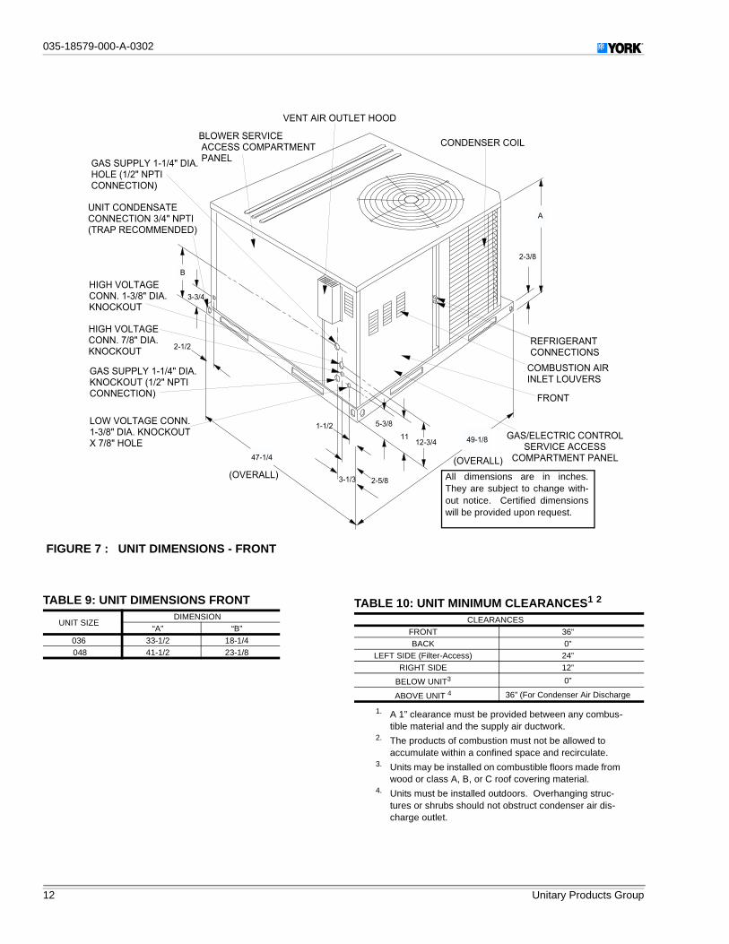
FIGURE 7 : UNIT DIMENSIONS - FRONT
� � � � �
� � � � �
� � � � � �
� � � � �
� � � � � � � � �
� � � �
� �� � � � � � � � � �
�
� � � �
� � � � � � � � � � � � � � � � � �
� � � � � � � � � � � � � � � � � � � � � � � � � � � �� � � � �
� � � � � � � � � � � � � � � � � � � � !� � � � " � � � � � � � � �� � � � � � � � � #
� � � � � � � � � � � � � � � � � � � � � � � � � � � � � � �" � � � � � � � � � � � � � #
�
� � � � � � � � � � � � � � � ! � � � � � � � � � !$ � � � $ � � �
� � � � � � � � � � � � � � � ! � � � � � � � !$ � � � $ � � �
� � � � � � � � � � � � � � � � � � � � !$ � � � $ � � � � " � � � � � � � �� � � � � � � � � #
� � � � � � � � � � � � � � � !� � � � � � � � ! � $ � � � $ � � �% � � � � � � �
� � � � � � � � � � � �
� & � � � � � � �� � � � � � � � � �
� � � � � � � � � � � � � �� � � � � � � � � � �
& � � � �
� � � � � � � � � � � � � � � � � �� � � � � � � � � � �
� � � � � � � � � � � � � � �
" � � � � � � #
" � � � � � � #
All dimensions are in inches.They are subject to change with-out notice. Certified dimensionswill be provided upon request.
TABLE 9: UNIT DIMENSIONS FRONT
UNIT SIZEDIMENSION
“A” “B”
036 33-1/2 18-1/4048 41-1/2 23-1/8
TABLE 10: UNIT MINIMUM CLEARANCES1 2
1. A 1” clearance must be provided between any combus-tible material and the supply air ductwork.
2. The products of combustion must not be allowed toaccumulate within a confined space and recirculate.
CLEARANCES
FRONT 36”BACK 0”
LEFT SIDE (Filter-Access) 24”
RIGHT SIDE 12”
BELOW UNIT3
3. Units may be installed on combustible floors made fromwood or class A, B, or C roof covering material.
0”
ABOVE UNIT 4
4. Units must be installed outdoors. Overhanging struc-tures or shrubs should not obstruct condenser air dis-charge outlet.
36” (For Condenser Air Discharge
035-18579-000-A-0302
Unitary Products Group 13
��
FIGURE 8: UNIT DIMENSIONS - FRONT & BOTTOM
26 3/4
6
4 5/8
8 7/811 7/8 19 1/4
HIGH VOLTAGECONN. 1 3/32" DIA.KNOCKOUT FRONT
CONDENSATEDRAIN 3/4"' NPTI
GAS SUPPLY 1 5/8" DIA.KNOCKOUT (1/2" NPTICONNECTION)
LOW VOLTAGE CONN." DIA. KNOCKOUT/87
FIGURE 9: UNIT DIMENSIONS - BACK & BOTTOM
� � � � �
� �
� � � � � �
� �
� � � � �
� � � � �
� � � � �
� �
�
� � � � � �
� � � � �
� � � �
� � � � � �
� � � �
� � � � � �
� � � � � � �
� � � �
� � � � � � � � � � � � �
� � � � � � � � �
� � � � � � � � � � � �
� � � � � � � � �
� � � � � � � � � �
� � � � � � � � �
� � � � � � � � � � �
� � � � � � � � �
� � � �
��035-18579-000-A-0302
14 Unitary Products Group
SEQUENCE OF OPERATION
The unit is controlled by a conventional four wire heating/cooling thermostat common to this class of equipment.
HEATING
When the thermostat calls for HEAT, the thermostat terminalW is energized, energizing the combustion air blower.
After airflow is established, the air proving switch closes, thehot surface ignitor is energized and the pilot valve opensigniting the pilot flame.
The flame rod senses a flame and de-energizes the ignitoropening the main gas valve and the main burners light.
30 seconds after the main burners light the circulating fan isenergized at the heating speed.
When the thermostat is satisfied, terminal W is de-energized,de-energizing the ignition system closing the gas valve.
After a 5 second postpurge timing period, the combustion airblower is de-energized and the heat fan off timing begins.
When this field selected heat fan off timing is completed thecirculating fan is de-energized.
If the primary, rollout and auxiliary limit switches open, thethermostat and ignition system is de-energized and the gasvalve closes. The combustion blower and the circulating fan,at heat speed, are energized.
The combustion blower remains energized for the 5 secondpostpurge timing period if the primary, rollout and auxiliarylimit switches remake the contact (the rollout and auxiliarylimit switches must be manually reset). The circulating fanremains energized for the selected heat delay off timing.
Normal operation of the system resumes.
COOLING
When the thermostat calls for COOL, the thermostat termi-nals G and Y are energized signaling the compressor andoutdoor fan to run.
After a cool fan on delay timing of 2 seconds, the circulatingfan is energized at cooling speed.
When the thermostat is satisfied, terminals G and Y are de-energized, de-energizing the compressor and outdoor fan.
After a cool fan off delay timing of 30 seconds the circulatingfan is de-energized.
CIRCULATING FAN
When the thermostat calls for FAN, the thermostat terminal Gis energized signaling the circulating fan to run at the heatspeed 2 seconds after the G terminal is energized.
If a call for HEAT occurs, the circulating fan continues to runat the heat speed.
If a call for COOL occurs, the circulating fan switches to coolspeed after a 4 second delay.
When the thermostat ends the call for FAN, the thermostatterminal G is de-energized, de-energizing the circulating fan.
START-UP
PRE-START CHECK LIST
Complete the following checks before starting the unit.
1. Check the type of gas being supplied. Be sure that it isthe same as listed on the unit nameplate.
2. Make sure that the vent outlet air hoods has been prop-erly installed.
OPERATING INSTRUCTIONS
1. STOP! Read the information on the unit safety label.
2. Set the thermostat to the OFF position.
3. Turn off all electrical power to the unit.
4. DO NOT try to light the burners by hand. This applianceis equipped with an ignition device which automaticallylights the burners.
5. Remove the access panel.
6. Turn the gas valve switch to the OFF position.
7. Wait five (5) minutes to clear out any gas. If you thensmell gas, STOP! Follow B in the information on the unitsafety label. If you don't smell gas, go to the next step.
8. Turn the gas valve switch to the ON position.
9. Replace the control access panel.
10. Turn on all electric power to the unit.
11. Set the thermostat to the desired setting.
12. If the unit will not operate, follow the instructions To TurnOff Gas To Appliance and call your service technician orgas supplier.

035-18579-000-A-0302
Unitary Products Group 15
��
TO TURN OFF GAS TO UNIT
1. Set the thermostat to the OFF position.
2. Turn off all electric power to the appliance if service is tobe performed.
3. Remove the control access panel.
4. Turn the gas valve switch to the OFF position. DO NOTFORCE.
5. Replace the control access panel.
POST-START CHECK LIST (GAS)
After the entire control circuit has been energized and theheating section is operating, make the following checks:
1. Check for gas leaks in the unit piping as well as the sup-ply piping.
2. Check for correct manifold gas pressures. See CheckingGas Input.
3. Check the supply gas pressure. It must be within the lim-its shown on rating nameplate. Supply pressure shouldbe checked with all gas appliances in the building at fullfire. At no time should the standby gas line pressureexceed 10.5", nor the operating pressure drop below4.5" for natural gas units. If gas pressure is outside theselimits, contact the local gas utility for corrective action.
MANIFOLD GAS PRESSURE ADJUSTMENT
Small adjustments to the gas flow may be made by turningthe pressure regulator adjusting screw on the automatic gasvalve. Refer to Figure 10.
Adjust as follows:
1. Remove the cap from the valve body. See Figure 11 forlocation.
2. To decrease the gas pressure, turn the adjusting screwcounterclockwise.
3. To increase the gas pressure, turn the adjusting screwclockwise.
NOTE: The correct manifold pressure for natural gas fur-naces is 3.5 IWG. The correct manifold pressure forpropane (LP) is 10.0 IWG.
BURNER INSTRUCTIONS
To check or change the burners, CLOSE THE MAIN MAN-UAL SHUT-OFF VALVE AND SHUT OFF ALL POWER TOTHE UNIT.
1. Remove the two (2) #8 screws holding each burner inplace.
2. Remove the burner assembly from the manifold assem-bly by moving the burner assembly forward, turn at anangle and pull back.
3. Burners are now accessible for service.
HOT SURFACE PILOT INSTRUCTIONS
To adjust the pilot flame:
FIGURE 10: GAS VALVE - FRONT
� � � � � � � � � �� � � � � � � � � � � � � �� � � � � � �
� � � � � � �� � � � � � � � �� � � � � � � � �
� � � � � � � � � � � � � � �� � � � � � � � �
� � � � � � �� � � � � � � �� � �
� � � � � �� � � � � � �
� � � � � � � � � �� � � � � � � �
� � � � � � � �� � � � � � � � �
� � � �� � � � � � � � � �
FIGURE 11: GAS VALVE - REAR
FIGURE 12: PROPER FLAME ADJUSTMENT
� � � � � � � � � � � � � � � � � � �
� � � � � � � � � � � �� � � � � �
� � � � � � � � � � � � � � � �
� � � � � � � � � � � � � � � �� � � � � � � � � �� � � � � � � � � � � �
� � �

��035-18579-000-A-0302
16 Unitary Products Group
1. Remove the pilot adjustment cover screw.
2. Adjust the pilot adjustment screw to achieve the properpilot flame.
3. The pilot flame should envelope 3/8 inch of the end ofthe flame sensor and not contain any yellow color, seeFigure 12.
4. Replace the pilot adjustment cover screw after the pilotflame is set.
To check, adjust or remove the hot surface pilot assembly,CLOSE THE MAIN MANUAL SHUT-OFF VALVE AND SHUTOFF ALL POWER TO THE UNIT.
1. Disconnect the wiring from the gas valve to the hot sur-face pilot assembly.
2. Remove the two (2) #8 screws holding the hot surfacepilot assembly in place.
3. Remove the hot surface pilot assembly.
To remove the hot surface ignitor and flame sensor assem-bly:
1. Remove the clip attaching the ignitor and sensor assem-bly as shown in Figure 13.
2. Lift the pilot and sensor from the assembly. Care must betaken not to damage the pilot or sensor when removingthis assembly.
ADJUSTMENT OF TEMPERATURE RISE
After about 20 minutes of operation, determine the furnacetemperature rise. Take readings of both the return air and the
heated air in the ducts about six feet from the furnace wherethey will not be affected by radiant heat.
The temperature rise (or temperature difference between thereturn air and the heated air from the furnace) must lie withinthe range shown on the rating plate and the data in Tables 3and 4.
After the temperature rise has been determined, the CFM canbe calculated as follows:
DIRECT DRIVE BLOWER
All units have direct drive, constant CFM blower motors.Refer to the unit wiring diagram, Table 1 for the desired cool-ing CFM. Heating CFM is preset at the factory.
CHECKING GAS INPUT
NATURAL GAS
1. Turn off all other gas appliances connected to the gasmeter.
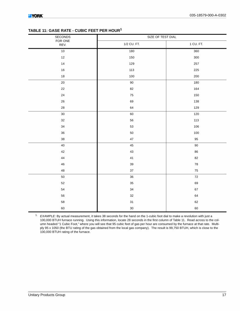
2. With the furnace turned on, measure the time needed forone revolution of the hand on the smallest dial on themeter. A typical gas meter usually has a 1/2 or a 1 cubicfoot test dial.
3. Using the number of seconds for each revolution and thesize of the test dial increment, find the cubic feet of gasconsumed per hour from Table 11.
If the actual input is not within 5% of the furnace rating withallowance being made for the permissible range of the regu-lator setting, replace the orifice spuds with spuds of theproper size.
NOTE: To find the BTU input, multiply the number of cubicfeet of gas consumed per hour by the BTU contentof the gas in your particular locality. (Contact yourgas company for this information since it varieswidely from city to city.)
FIGURE 13: IGNITOR AND FLAME SENSORASSEMBLY
Degrees F Temp RiseBTUH Output
1.08 CFM×------------------------------------=
OR
CFMBTUH Output
1.08 Degrees F Temp Rise×-------------------------------------------------------------------------=
035-18579-000-A-0302
Unitary Products Group 17
��
TABLE 11: GASE RATE - CUBIC FEET PER HOUR1
SECONDSFOR ONE
REV.
SIZE OF TEST DIAL
1/2 CU. FT. 1 CU. FT.
10 180 360
12 150 300
14 129 257
16 113 225
18 100 200
20 90 180
22 82 164
24 75 150
26 69 138
28 64 129
30 60 120
32 56 113
34 53 106
36 50 100
38 47 95
40 45 90
42 43 86
44 41 82
46 39 78
48 37 75
50 36 72
52 35 69
54 34 67
56 32 64
58 31 62
60 30 60
1. EXAMPLE: By actual measurement, it takes 38 seconds for the hand on the 1-cubic foot dial to make a revolution with just a100,000 BTUH furnace running. Using this information, locate 28 seconds in the first column of Table 11. Read across to the col-umn headed “1 Cubic Foot,” where you will see that 95 cubic feet of gas per hour are consumed by the furnace at that rate. Multi-ply 95 x 1050 (the BTU rating of the gas obtained from the local gas company). The result is 99,750 BTUH, which is close to the100,000 BTUH rating of the furnace.
��035-18579-000-A-0302
18 Unitary Products Group
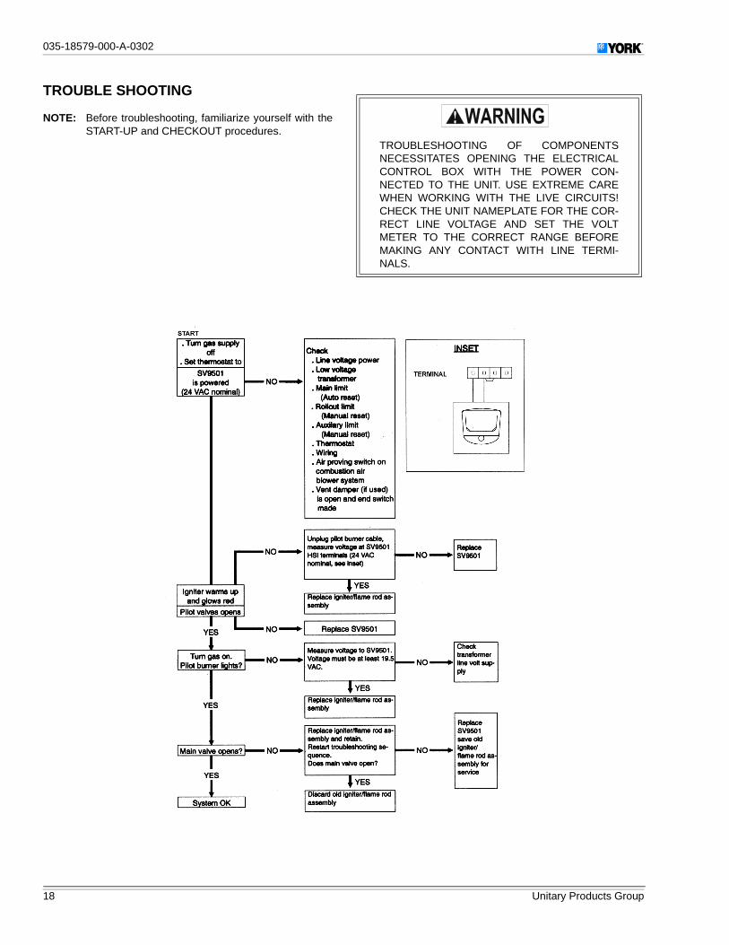
TROUBLE SHOOTING
NOTE: Before troubleshooting, familiarize yourself with theSTART-UP and CHECKOUT procedures.
TROUBLESHOOTING OF COMPONENTSNECESSITATES OPENING THE ELECTRICALCONTROL BOX WITH THE POWER CON-NECTED TO THE UNIT. USE EXTREME CAREWHEN WORKING WITH THE LIVE CIRCUITS!CHECK THE UNIT NAMEPLATE FOR THE COR-RECT LINE VOLTAGE AND SET THE VOLTMETER TO THE CORRECT RANGE BEFOREMAKING ANY CONTACT WITH LINE TERMI-NALS.
035-18579-000-A-0302
Unitary Products Group 19
��
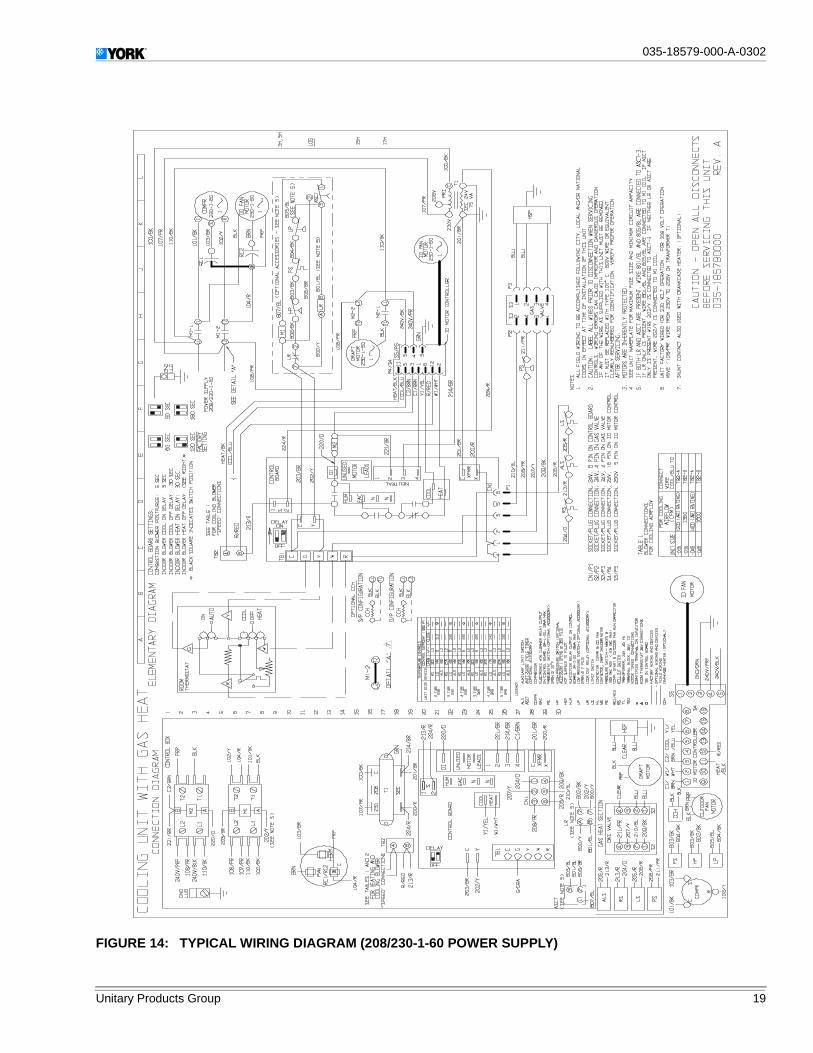
FIGURE 14: TYPICAL WIRING DIAGRAM (208/230-1-60 POWER SUPPLY)
��035-18579-000-A-0302
20 Unitary Products Group
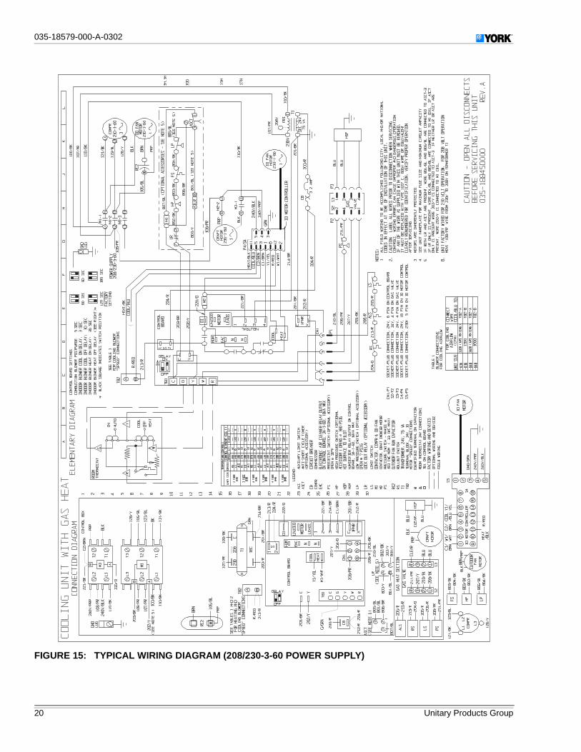
FIGURE 15: TYPICAL WIRING DIAGRAM (208/230-3-60 POWER SUPPLY)

035-18579-000-A-0302
Unitary Products Group 21
��
FIGURE 16: TYPICAL WIRING DIAGRAM (460-3-60 POWER SUPPLY)
��035-18579-000-A-0302
22 Unitary Products Group
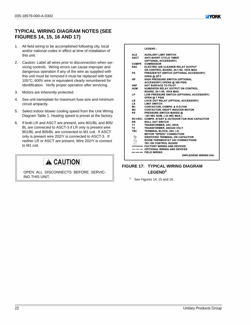
TYPICAL WIRING DIAGRAM NOTES (SEEFIGURES 14, 15, 16 AND 17)
1. All field wiring to be accomplished following city, localand/or national codes in effect at time of installation ofthis unit.
2. Caution: Label all wires prior to disconnection when ser-vicing controls. Wiring errors can cause improper anddangerous operation if any of the wire as supplied withthis unit must be removed it must be replaced with type105°C, 600V wire or equivalent clearly renumbered foridentification. Verify proper operation after servicing.
3. Motors are inherently protected.
4. See unit nameplate for maximum fuse size and minimumcircuit ampacity.
5. Select indoor blower cooling speed from the Unit WiringDiagram Table 1. Heating speed is preset at the factory.
6. If both LR and ASCT are present, wire 801/BL and 805/BL are connected to ASCT-3 if LR only is present wire801/BL and 805/BL are connected to M1 coil. If ASCTonly is present wire 202/Y is connected to ASCT-3. Ifneither LR or ASCT are present, Wire 202/Y is connectto M1 coil.
OPEN ALL DISCONNECTS BEFORE SERVIC-ING THIS UNIT.
FIGURE 17: TYPICAL WIRING DIAGRAMLEGEND1
1. See Figures 14, 15 and 16.
ALS
ASCT
COMPR
EAC
FS
HP
HSP
HUM
LP
LR
LS
M1
M2
PS
RC1/RC2
RS
T1
T2
TB2
ELECTRIC AIR CLEANER RELAY OUTPUT
LEGEND :
AUXILARY LIMIT SWITCH
ANTI-SHORT CYCLE TIMER
(OPTIONAL ACCESSORY)
COMRESSOR
ON CONTROL BOARD, 24-1-60, 18VA MAX.
FREEZESTAT SWITCH (OPTIONAL ACCESSORY)
OPEN @ 250 F
HIGH PRESSURE SWITCH (OPTIONAL
ACCESSORY) OPENS @ 380 PSIG
HOT SURFACE TO PILOT
HUMIDIFER RELAY OUTPUT ON CONTROL
BOARD, 24-1-60, 18VA MAX.
LOW PRESSURE SWITCH (OPTIONAL ACCESSORY)
OPEN @ 7 PSIG
LOCK OUT RELAY (OPTIOAL ACCESSORY)
LIMIT SWITCH
CONTACTOR, COMPR. & O.D.FAN
CONTACTOR, DRAFT INDUCER MOTOR
PRESSURE SWITCH MAKES @
.193 IWC NOM. (.33 IWC MAX.)
COMPR. START & OUTDOOR FAN RUN CAPACITOR
ROLL OUT SWITCH
TRANSFORMER, 24V, 40VA
TRANSFORMER, 480/240 VOLT
TERMINAL BLOCK, 24V, I.D.
MOTOR "SPEED" CONNECTION
IDENTIFIED TERMINAL ON CAPACITOR
FIELD WIRING
DNPLEGEND WIRING DIA.
ROOM THERMOSTAT 24V CONNECTIONS
TB1 ON CONTROL BOARD
FACTORY WIRING AND DEVICES
OPITIONAL WIRING AND DEVICES

035-18579-000-A-0302
Unitary Products Group 23
��

Subject to change without notice. Printed in U.S.A.Copyright © by Unitary Products Group 2002. All rights reserved. Supersedes: Nothing 035-18579-000-A-0302
Unitary 5005 NormanProducts York OKGroup Drive 73069