installation instruction sliding freezer door type …...installation instruction sliding freezer...
TRANSCRIPT
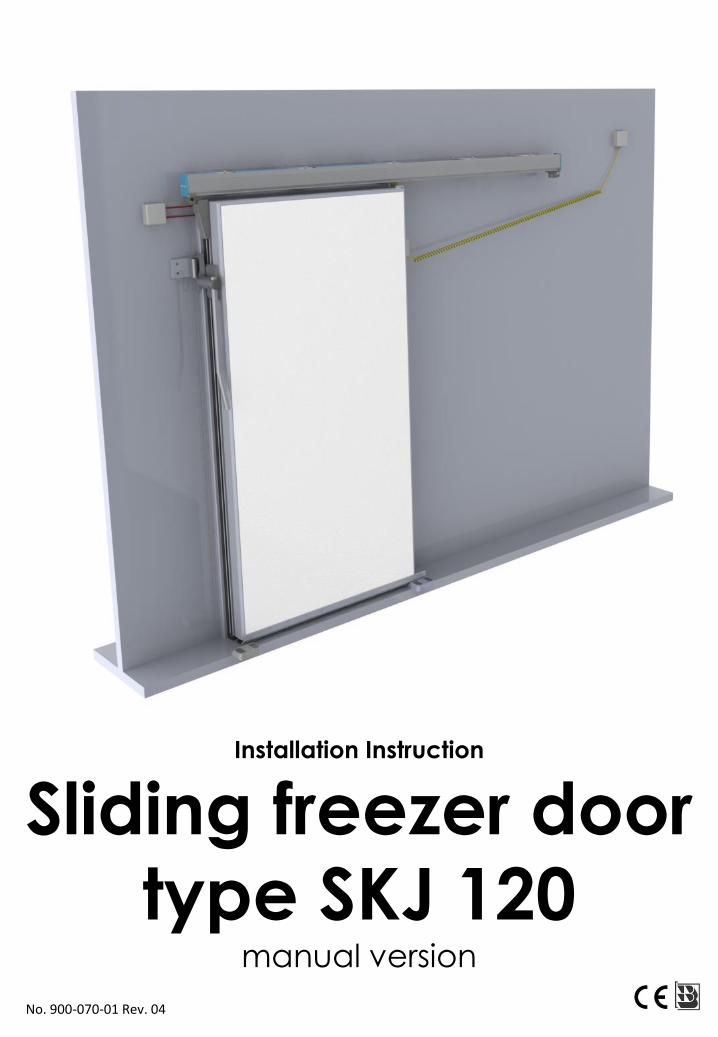
Installation Instruction
Sliding freezer door type SKJ 120
manual version
No. 900-070-01 Rev. 04
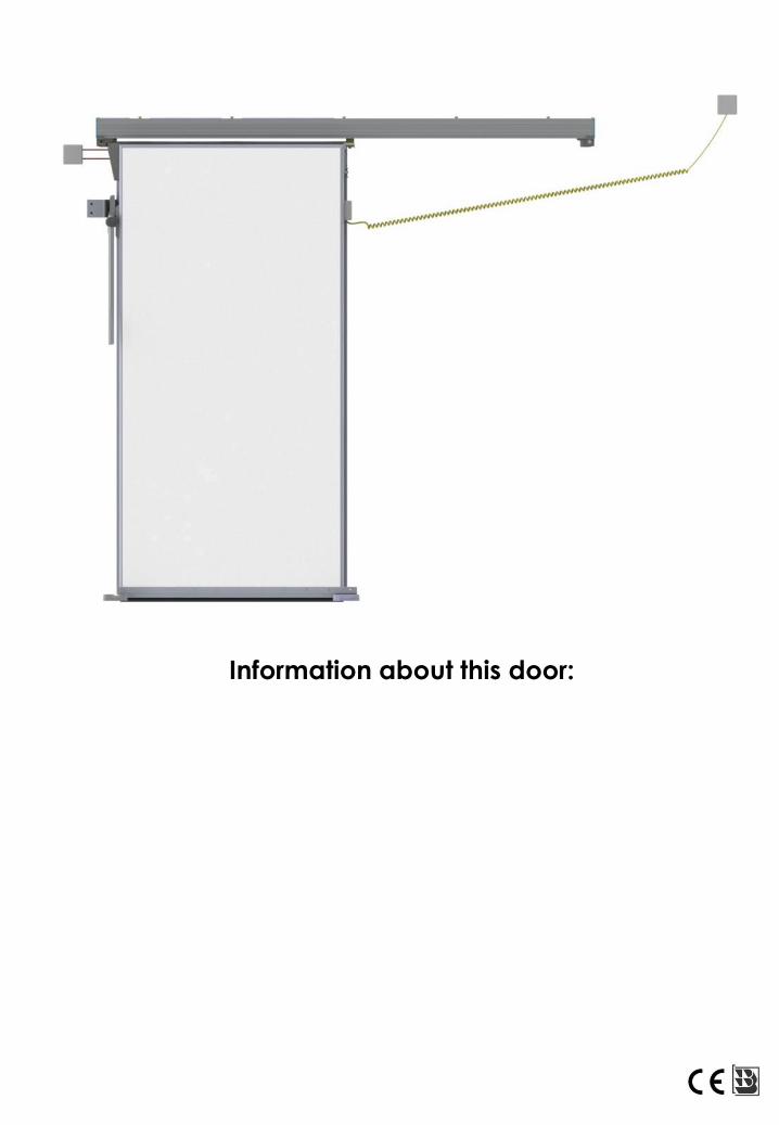
Information about this door:
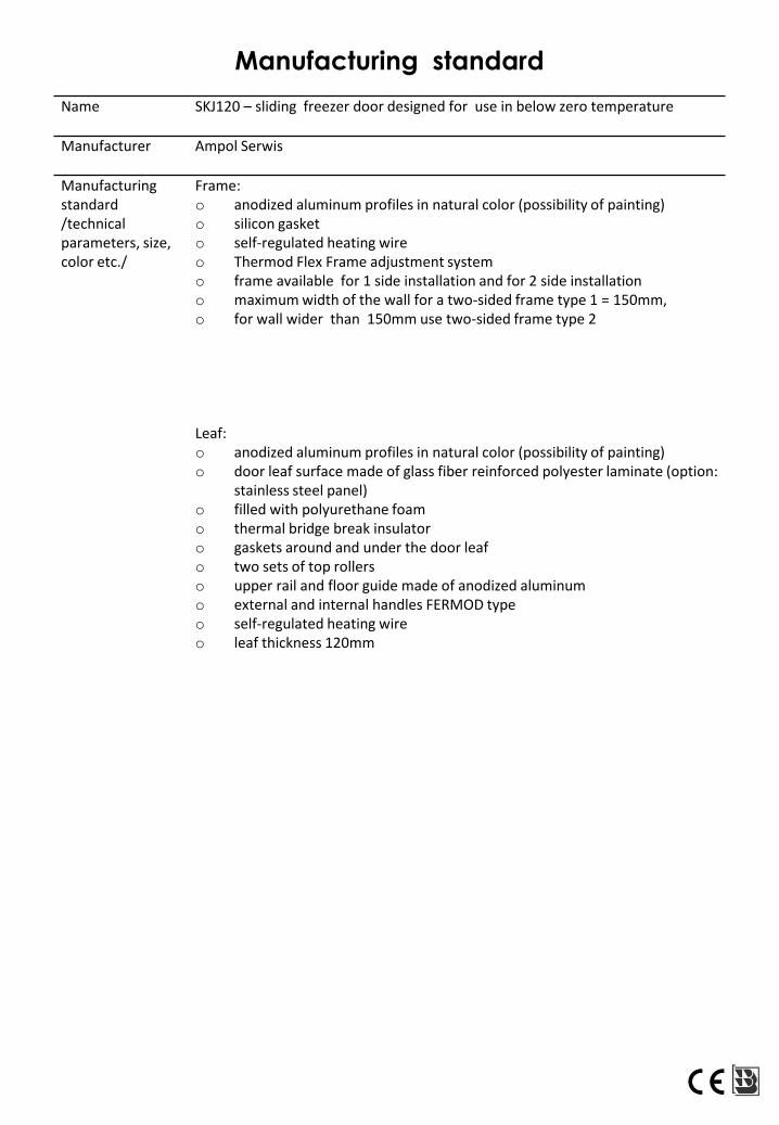
Name SKJ120 – sliding freezer door designed for use in below zero temperature
Manufacturer Ampol Serwis
Manufacturing standard/technical parameters, size, color etc./
Frame:o anodized aluminum profiles in natural color (possibility of painting)o silicon gasketo self-regulated heating wireo Thermod Flex Frame adjustment systemo frame available for 1 side installation and for 2 side installationo maximum width of the wall for a two-sided frame type 1 = 150mm,o for wall wider than 150mm use two-sided frame type 2
Leaf:o anodized aluminum profiles in natural color (possibility of painting)o door leaf surface made of glass fiber reinforced polyester laminate (option:
stainless steel panel)o filled with polyurethane foamo thermal bridge break insulatoro gaskets around and under the door leafo two sets of top rollerso upper rail and floor guide made of anodized aluminumo external and internal handles FERMOD typeo self-regulated heating wireo leaf thickness 120mm
Manufacturing standard
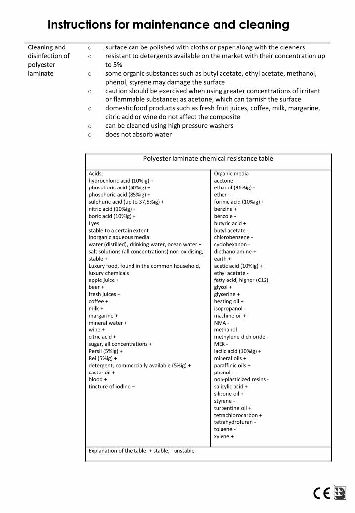
Instructions for maintenance and cleaning
Cleaning and disinfection of polyester laminate
o surface can be polished with cloths or paper along with the cleaners o resistant to detergents available on the market with their concentration up
to 5% o some organic substances such as butyl acetate, ethyl acetate, methanol,
phenol, styrene may damage the surfaceo caution should be exercised when using greater concentrations of irritant
or flammable substances as acetone, which can tarnish the surfaceo domestic food products such as fresh fruit juices, coffee, milk, margarine,
citric acid or wine do not affect the compositeo can be cleaned using high pressure washerso does not absorb water
Polyester laminate chemical resistance table
Acids:hydrochloric acid (10%ig) +phosphoric acid (50%ig) +phosphoric acid (85%ig) +sulphuric acid (up to 37,5%ig) +nitric acid (10%ig) +boric acid (10%ig) +Lyes:stable to a certain extentInorganic aqueous media:water (distilled), drinking water, ocean water +salt solutions (all concentrations) non-oxidising, stable +Luxury food, found in the common household, luxury chemicalsapple juice +beer +fresh juices +coffee +milk +margarine +mineral water +wine +citric acid +sugar, all concentrations +Persil (5%ig) +Rei (5%ig) +detergent, commercially available (5%ig) +caster oil +blood +tincture of iodine –
Organic mediaacetone -ethanol (96%ig) -ether -formic acid (10%ig) +benzine +benzole -butyric acid +butyl acetate -chlorobenzene -cyclohexanon -diethanolamine +earth +acetic acid (10%ig) +ethyl acetate -fatty acid, higher (C12) +glycol +glycerine +heating oil +isopropanol -machine oil +NMA -methanol -methylene dichloride -MEK -lactic acid (10%ig) +mineral oils +paraffinic oils +phenol -non-plasticized resins -salicylic acid +silicone oil +styrene -turpentine oil +tetrachlorocarbon +tetrahydrofuran -toluene -xylene +
Explanation of the table: + stable, - unstable
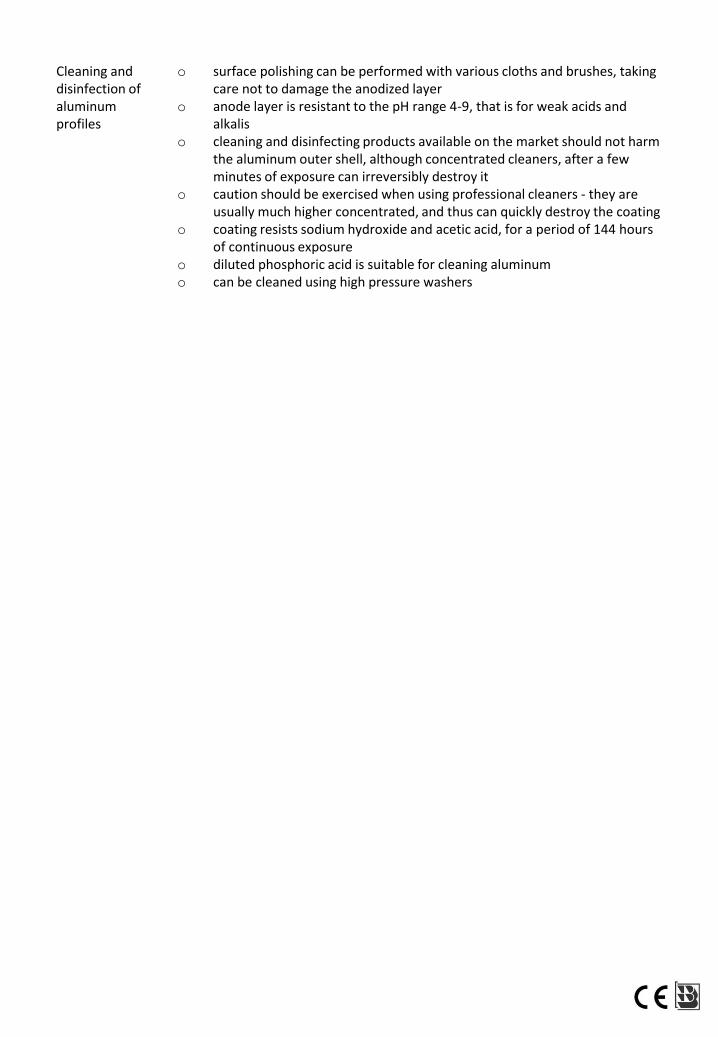
Cleaning and disinfection of aluminum profiles
o surface polishing can be performed with various cloths and brushes, taking care not to damage the anodized layer
o anode layer is resistant to the pH range 4-9, that is for weak acids and alkalis
o cleaning and disinfecting products available on the market should not harm the aluminum outer shell, although concentrated cleaners, after a few minutes of exposure can irreversibly destroy it
o caution should be exercised when using professional cleaners - they are usually much higher concentrated, and thus can quickly destroy the coating
o coating resists sodium hydroxide and acetic acid, for a period of 144 hours of continuous exposure
o diluted phosphoric acid is suitable for cleaning aluminum o can be cleaned using high pressure washers
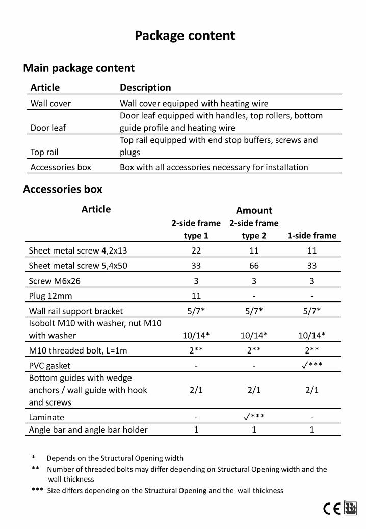
Article Description
Wall cover Wall cover equipped with heating wire
Door leaf
Door leaf equipped with handles, top rollers, bottom
guide profile and heating wire
Top rail
Top rail equipped with end stop buffers, screws and
plugs
Accessories box Box with all accessories necessary for installation
Article Amount2-side frame
type 1
2-side frame
type 2 1-side frame
Sheet metal screw 4,2x13 22 11 11
Sheet metal screw 5,4x50 33 66 33
Screw M6x26 3 3 3
Plug 12mm 11 - -
Wall rail support bracket 5/7* 5/7* 5/7*
Isobolt M10 with washer, nut M10
with washer 10/14* 10/14* 10/14*
M10 threaded bolt, L=1m 2** 2** 2**
PVC gasket - - ✓***
Bottom guides with wedge
anchors / wall guide with hook
and screws
2/1 2/1 2/1
Laminate - ✓*** -
Angle bar and angle bar holder 1 1 1
Package content
Main package content
Accessories box
* Depends on the Structural Opening width
** Number of threaded bolts may differ depending on Structural Opening width and the wall thickness
*** Size differs depending on the Structural Opening and the wall thickness
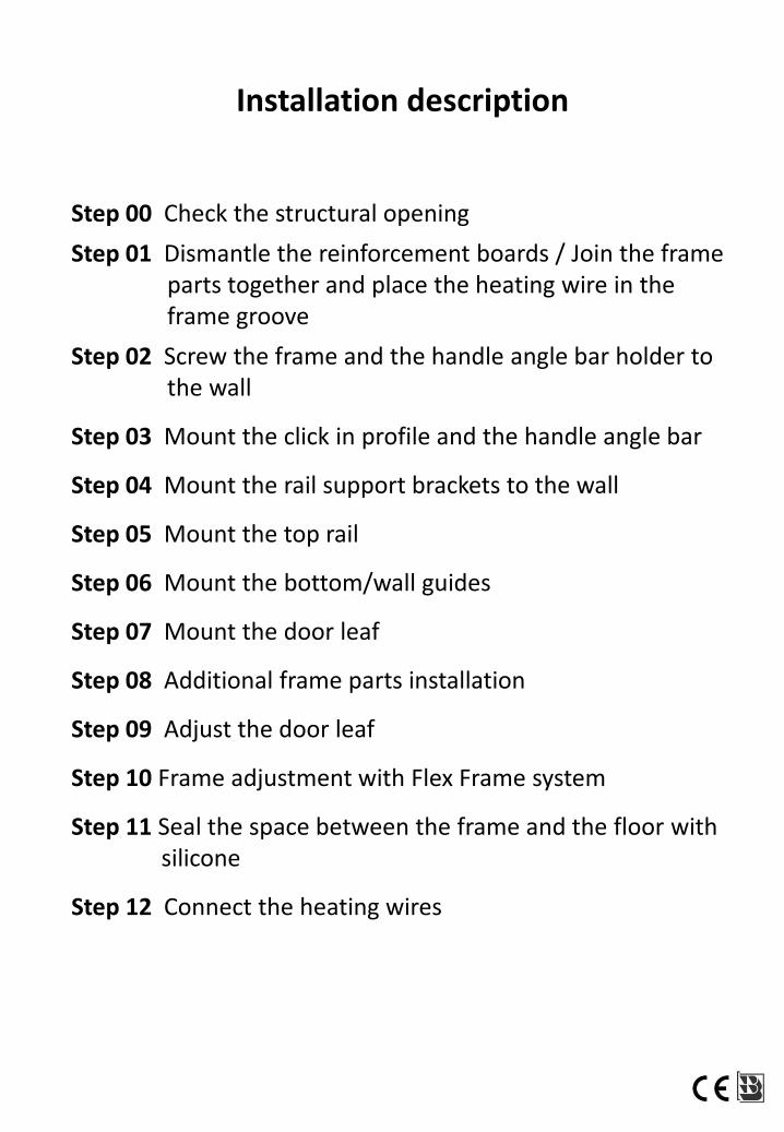
Installation description
Step 00 Check the structural opening
Step 01 Dismantle the reinforcement boards / Join the frame parts together and place the heating wire in the frame groove
Step 02 Screw the frame and the handle angle bar holder to the wall
Step 03 Mount the click in profile and the handle angle bar
Step 04 Mount the rail support brackets to the wall
Step 05 Mount the top rail
Step 06 Mount the bottom/wall guides
Step 07 Mount the door leaf
Step 08 Additional frame parts installation
Step 09 Adjust the door leaf
Step 10 Frame adjustment with Flex Frame system
Step 11 Seal the space between the frame and the floor withsilicone
Step 12 Connect the heating wires
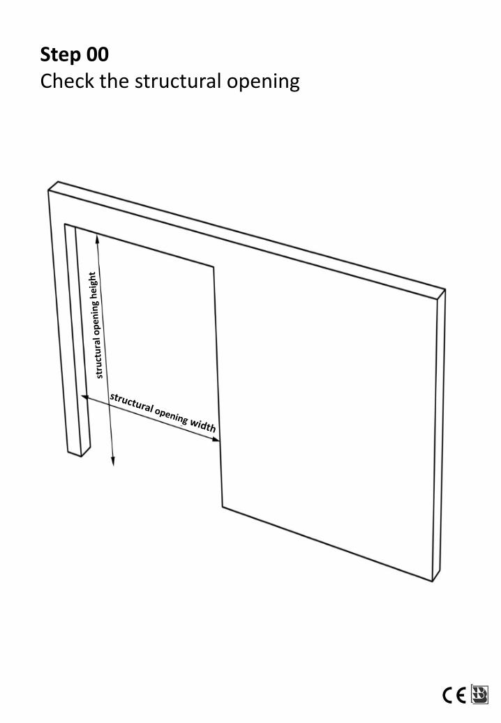
Step 00Check the structural opening
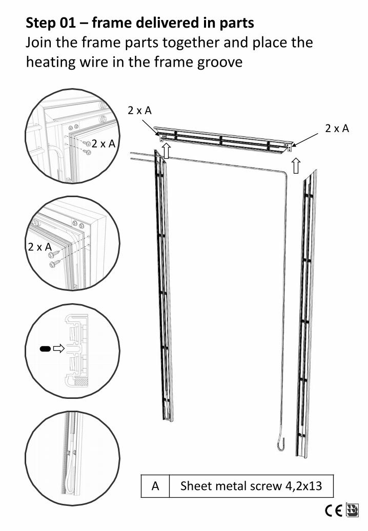
Step 01 – frame delivered in partsJoin the frame parts together and place the heating wire in the frame groove
A Sheet metal screw 4,2x13
2 x A
2 x A
2 x A
2 x A
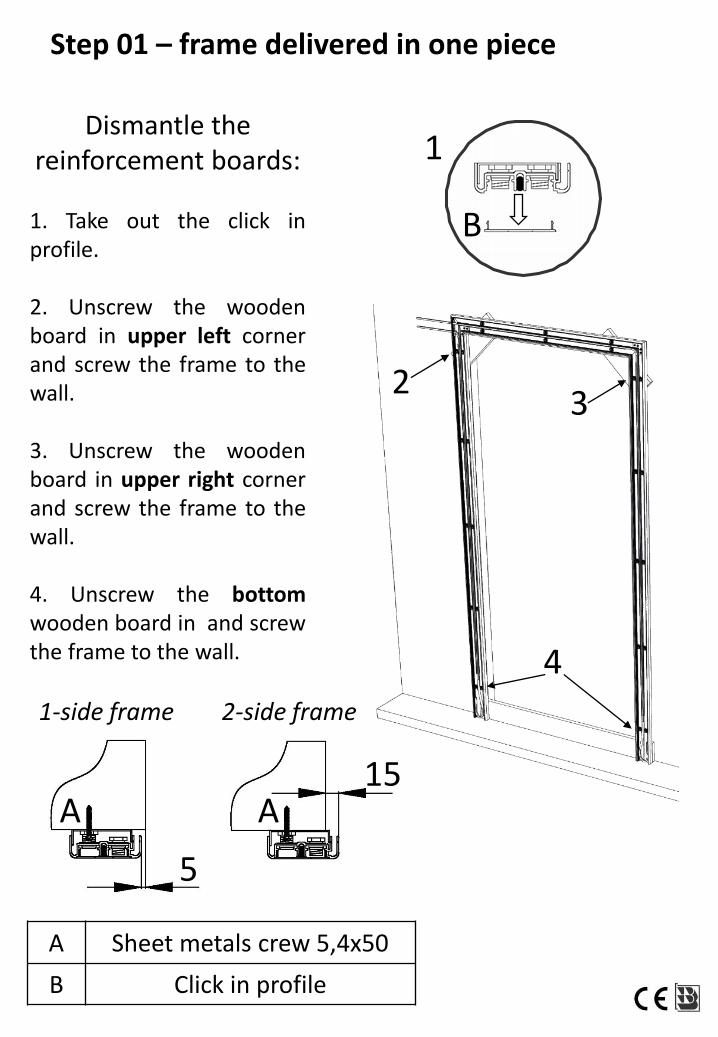
Step 01 – frame delivered in one piece
3
A Sheet metals crew 5,4x50
B Click in profile
4
Dismantle the reinforcement boards:
1. Take out the click inprofile.
2. Unscrew the woodenboard in upper left cornerand screw the frame to thewall.
3. Unscrew the woodenboard in upper right cornerand screw the frame to thewall.
4. Unscrew the bottomwooden board in and screwthe frame to the wall.
1-side frame 2-side frame
5
15
2
B
A A
1
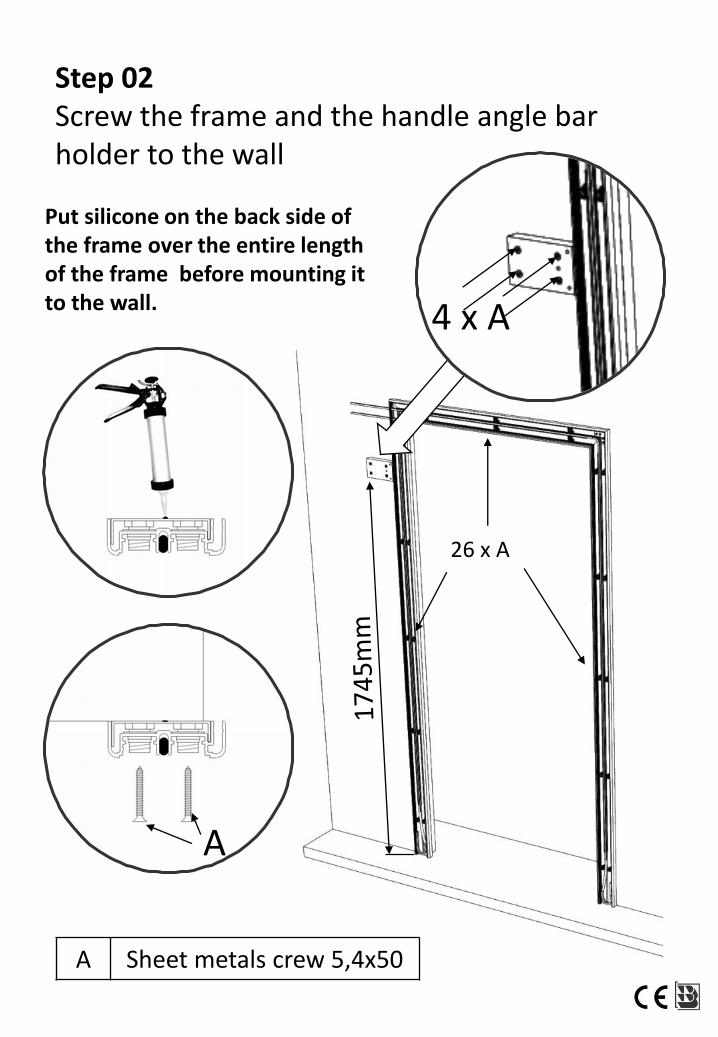
Step 02Screw the frame and the handle angle bar holder to the wall
26 x A
A Sheet metals crew 5,4x50
4 x A
A
Put silicone on the back side of the frame over the entire lengthof the frame before mounting itto the wall.
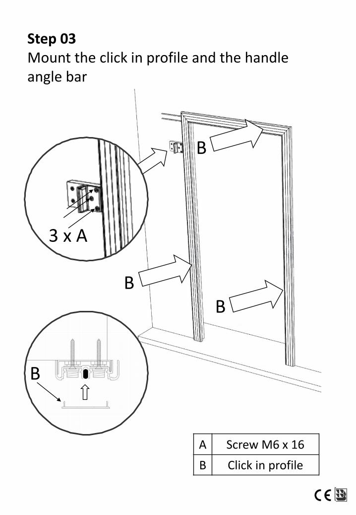
Step 03Mount the click in profile and the handle angle bar
3 x A
B
B
BB
A Screw M6 x 16
B Click in profile
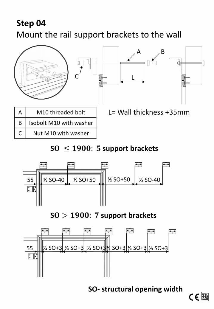
Step 04Mount the rail support brackets to the wall
SO- structural opening width
55 ½ SO-40
55 ⅓ SO+3
½ SO+50 ½ SO+50 ½ SO-40
⅓ SO+3 ⅓ SO+3⅓ SO+3 ⅓ SO+3 ⅓ SO+3
S𝐎 > 𝟏𝟗𝟎𝟎: 𝟕 support brackets
S𝐎 ≤ 𝟏𝟗𝟎𝟎: 𝟓 support brackets
L= Wall thickness +35mm
B
A M10 threaded bolt
B Isobolt M10 with washer
C Nut M10 with washer
A
C L
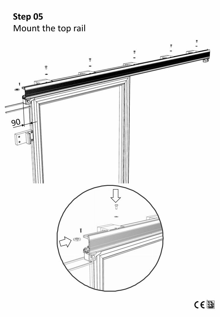
Step 05Mount the top rail
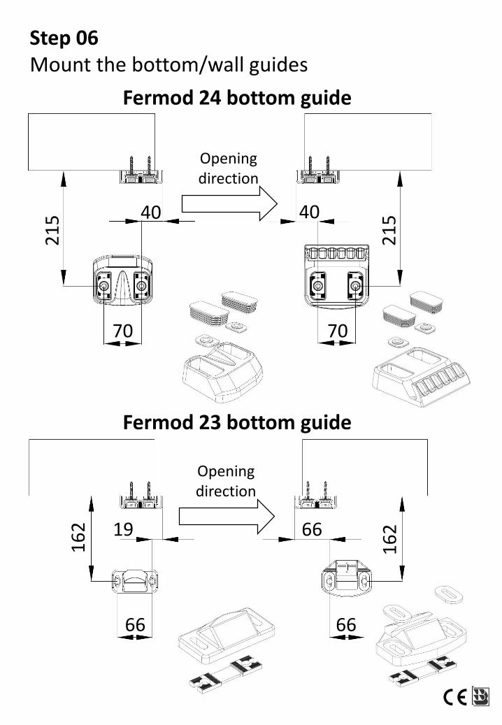
Step 06Mount the bottom/wall guides
40 40
70 70
21
5
21
5
Openingdirection
19 66
66 66
16
2
16
2
Openingdirection
Fermod 23 bottom guide
Fermod 24 bottom guide
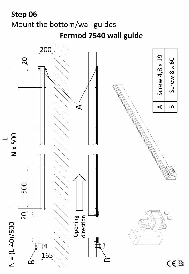
165
Fermod 7540 wall guide
Op
enin
gd
irec
tio
n
N =
(L-
40
)/5
00
Step 06Mount the bottom/wall guides
N x
50
0
50
02
02
0
L
200
BB
A
Scre
w4
,8 x
19
Scre
w8
x 6
0
A B
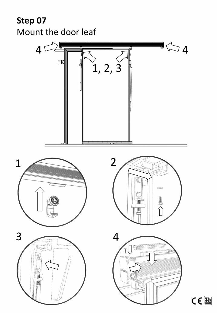
Step 07Mount the door leaf
1 2
3
1, 2, 3
4 4
4
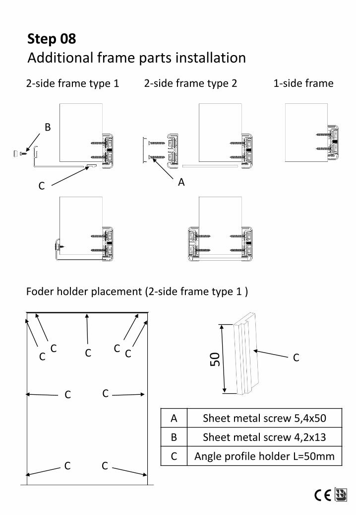
C
2-side frame type 1 2-side frame type 2 1-side frame
A Sheet metal screw 5,4x50
B Sheet metal screw 4,2x13
C Angle profile holder L=50mm
C A
B
Foder holder placement (2-side frame type 1 )
C C
CC
CC C C C
Step 08Additional frame parts installation
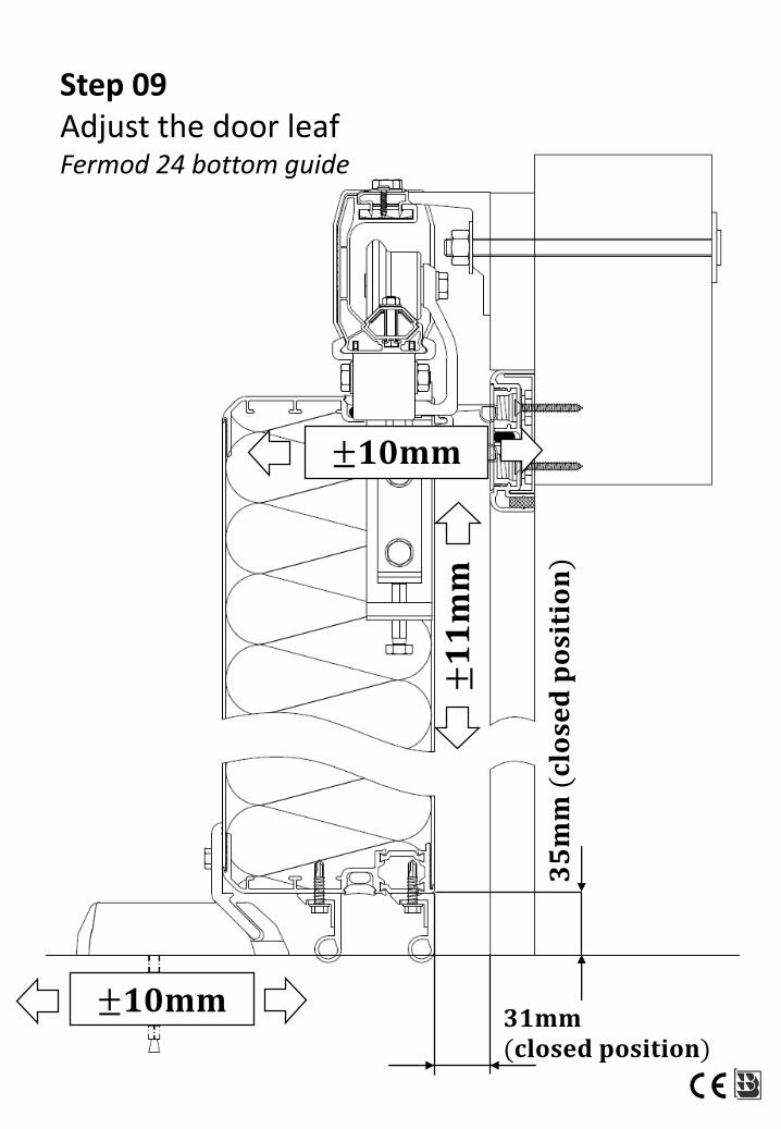
Step 09Adjust the door leafFermod 24 bottom guide
±𝟏𝟎𝐦𝐦
±𝟏𝟎𝐦𝐦±𝟏𝟏𝐦𝐦
𝟑𝟓𝐦𝐦
(𝐜𝐥𝐨𝐬𝐞𝐝𝐩𝐨𝐬𝐢𝐭𝐢𝐨𝐧)
𝟑𝟏𝐦𝐦(𝐜𝐥𝐨𝐬𝐞𝐝 𝐩𝐨𝐬𝐢𝐭𝐢𝐨𝐧)
±𝟕, 𝟓𝐦𝐦
±𝟕, 𝟓𝐦𝐦±𝟏𝟏𝐦𝐦
𝟑𝟓𝐦𝐦
(𝐜𝐥𝐨𝐬𝐞𝐝𝐩𝐨𝐬𝐢𝐭𝐢𝐨𝐧)
𝟑𝟏𝐦𝐦(𝐜𝐥𝐨𝐬𝐞𝐝 𝐩𝐨𝐬𝐢𝐭𝐢𝐨𝐧)
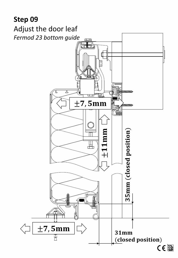
Step 09Adjust the door leafFermod 23 bottom guide
±𝟕𝐦𝐦
±𝟕𝐦𝐦
±𝟕𝐦𝐦
𝟑𝟓𝐦𝐦
(𝐜𝐥𝐨𝐬𝐞𝐝𝐩𝐨𝐬𝐢𝐭𝐢𝐨𝐧)
𝟑𝟏𝐦𝐦 (𝐜𝐥𝐨𝐬𝐞𝐝 𝐩𝐨𝐬𝐢𝐭𝐢𝐨𝐧)
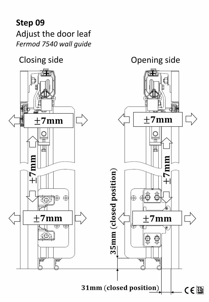
Step 09Adjust the door leafFermod 7540 wall guide
±𝟕𝐦𝐦
±𝟕𝐦𝐦
±𝟕𝐦𝐦
Closing side Opening side
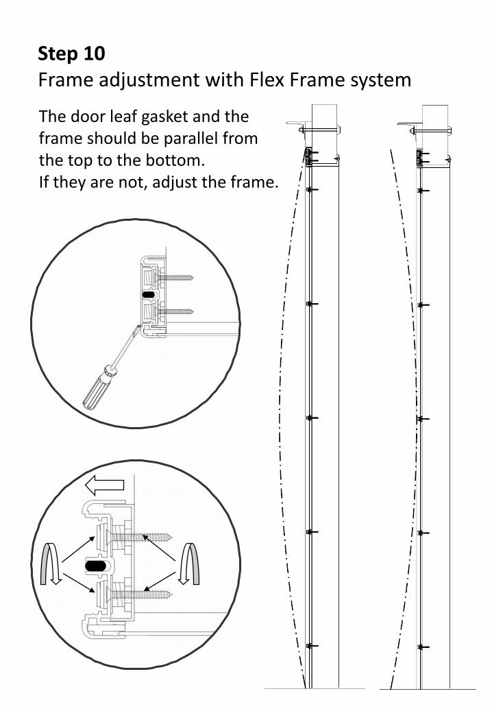
Step 10Frame adjustment with Flex Frame system
The door leaf gasket and the frame should be parallel from the top to the bottom. If they are not, adjust the frame.
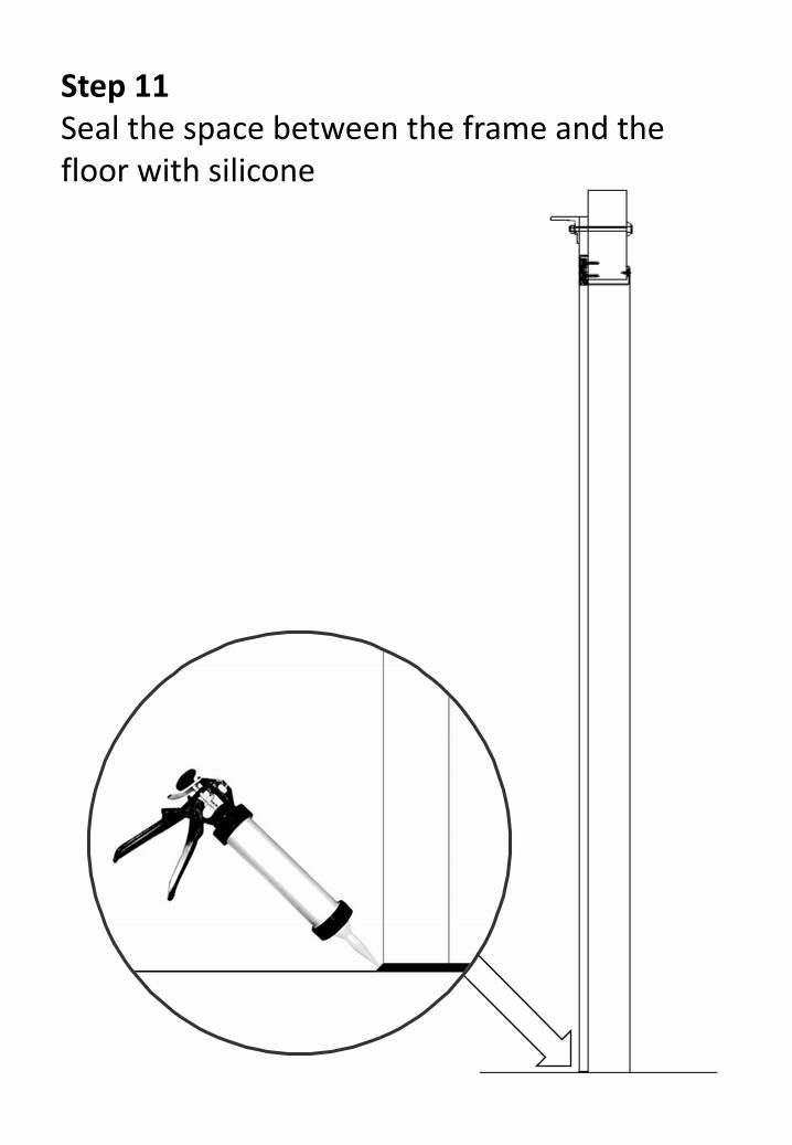
Step 11Seal the space between the frame and the floor with silicone
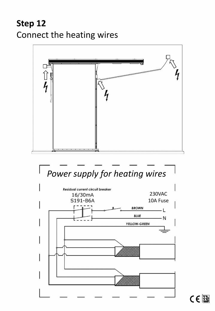
Step 12Connect the heating wires
Power supply for heating wires
230VAC10A Fuse