installation instructions - qualityedge.com · (9) 2. installation of the g-channel 1” under the...
TRANSCRIPT

Installation Instructions
(2)
Table of Contents
Installation Worksheet ..........................................................................................3
Calculation Chart .............................................................................................. 4–5
Installation Overview ............................................................................................6
Glossary of Terms .................................................................................................7
Determine Drainage Location ................................................................................8
Installation of the G-Channel ................................................................................9
Alternate Installation of the G-Channel .................................................................9
Installation of Side Cap .........................................................................................9
Installation of carrier ...........................................................................................10
Carrier Tips ..........................................................................................................11
Installation of Gutter .............................................................................................11
Side Cap Location .................................................................................................11
Notching the Gutter ..............................................................................................12
Ceiling Panel Alignment ........................................................................................12
Carrier Spacing ....................................................................................................12
Installing Remaining carriers ................................................................................12
Hanging Technique to Permanently Fasten carriers ...............................................13
Insulating the carrier ............................................................................................13
Straightness .........................................................................................................13
Installation of Panels ............................................................................................13
Gutter Specifics ....................................................................................................14
Prevent Water Wicking ..........................................................................................14
Boxing and Caulking .............................................................................................14
Installation of the Final Panel ...............................................................................14
G-Channel Specifics ..............................................................................................15
Flashing ...............................................................................................................15
Side Cap Specifics ................................................................................................15
Ceiling Fans ..........................................................................................................15
Cantilevers ...........................................................................................................16
Side Cap Flashing Outside and Under the Joist ......................................................16
Change in Direction of Panels ...............................................................................16
Column Tips .........................................................................................................17
Dryer Vents ...........................................................................................................17
Helpful Hint ..........................................................................................................17
(3)
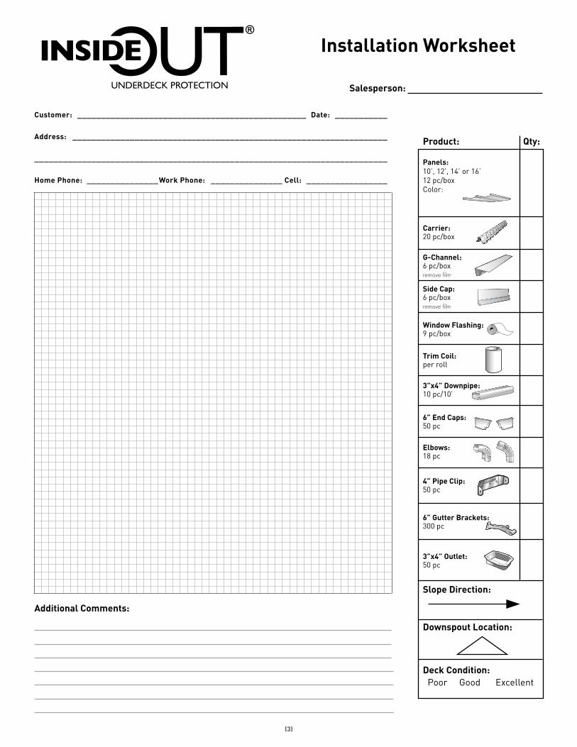
Installation Worksheet
Panels:10’, 12’, 14’ or 16’ 12 pc/boxColor:
Product: Qty:
Additional Comments:
Salesperson:
Carrier:20 pc/box
G-Channel:6 pc/boxremove film
Side Cap:6 pc/boxremove film
Window Flashing:9 pc/box
Trim Coil:per roll
3”x4” Downpipe:10 pc/10’
6” End Caps:50 pc
Elbows:18 pc
4” Pipe Clip:50 pc
6” Gutter Brackets:300 pc
Downspout Location:
Slope Direction:
Deck Condition: Poor Good Excellent
3”x4” Outlet:50 pc
1"
8.25"
Customer: ________________________________________________ Date: ___________
Address: __________________________________________________________________
__________________________________________________________________________
Home Phone: _______________Work Phone: _______________ Cell: _________________
(4)
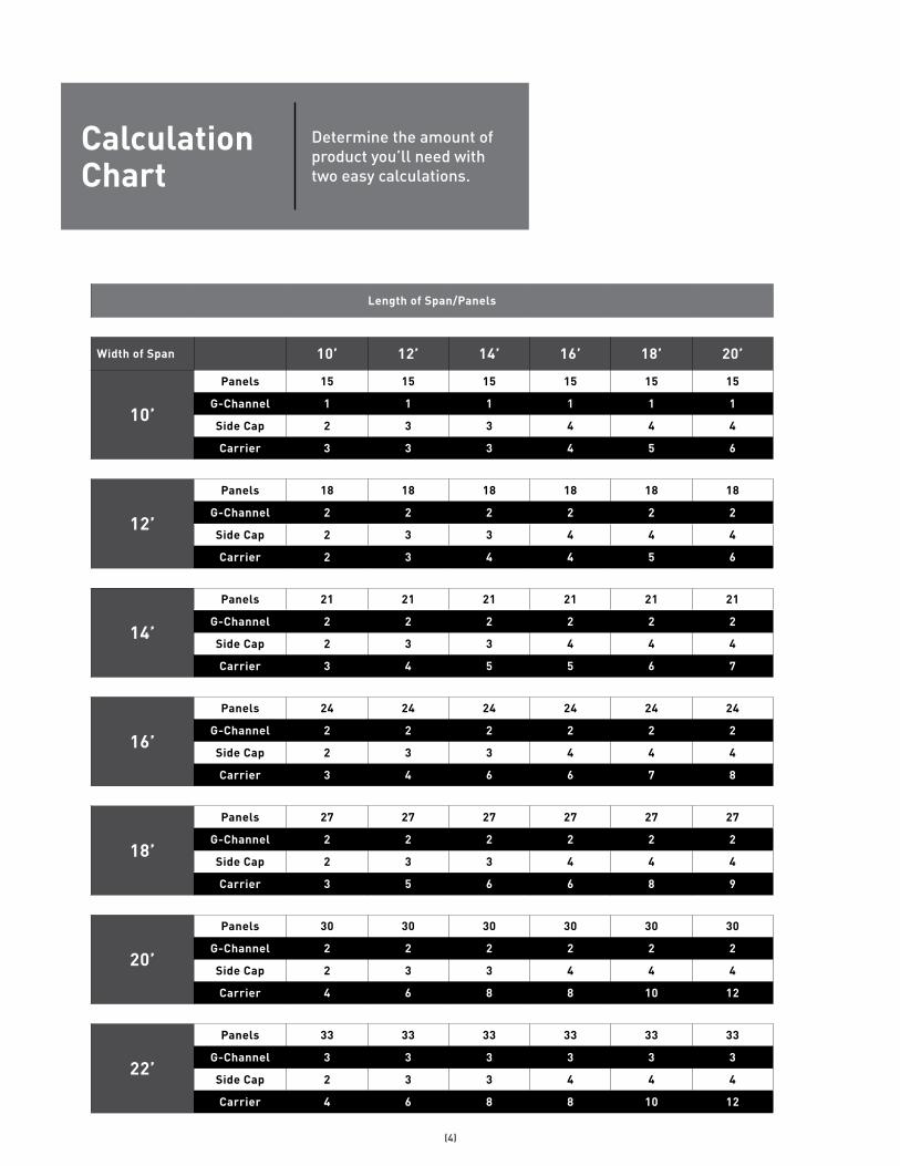
Length of Span/Panels
Width of Span 10’ 12’ 14’ 16’ 18’ 20’
10’
Panels 15 15 15 15 15 15
G-Channel 1 1 1 1 1 1
Side Cap 2 3 3 4 4 4
Carrier 3 3 3 4 5 6
12’
Panels 18 18 18 18 18 18
G-Channel 2 2 2 2 2 2
Side Cap 2 3 3 4 4 4
Carrier 2 3 4 4 5 6
14’
Panels 21 21 21 21 21 21
G-Channel 2 2 2 2 2 2
Side Cap 2 3 3 4 4 4
Carrier 3 4 5 5 6 7
16’
Panels 24 24 24 24 24 24
G-Channel 2 2 2 2 2 2
Side Cap 2 3 3 4 4 4
Carrier 3 4 6 6 7 8
18’
Panels 27 27 27 27 27 27
G-Channel 2 2 2 2 2 2
Side Cap 2 3 3 4 4 4
Carrier 3 5 6 6 8 9
20’
Panels 30 30 30 30 30 30
G-Channel 2 2 2 2 2 2
Side Cap 2 3 3 4 4 4
Carrier 4 6 8 8 10 12
22’
Panels 33 33 33 33 33 33
G-Channel 3 3 3 3 3 3
Side Cap 2 3 3 4 4 4
Carrier 4 6 8 8 10 12
Calculation Chart
Determine the amount of product you’ll need with two easy calculations.
(5)
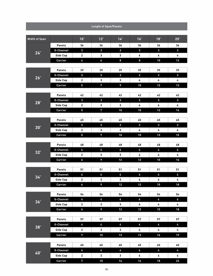
Length of Span/Panels
Width of Span 10’ 12’ 14’ 16’ 18’ 20’
24’
Panels 36 36 36 36 36 36
G-Channel 3 3 3 3 3 3
Side Cap 2 3 3 4 4 4
Carrier 4 6 8 8 10 12
26’
Panels 39 39 39 39 39 39
G-Channel 3 3 3 3 3 3
Side Cap 2 3 3 4 4 4
Carrier 5 7 9 10 12 13
28’
Panels 42 42 42 42 42 42
G-Channel 3 3 3 3 3 3
Side Cap 2 3 3 4 4 4
Carrier 5 7 10 10 12 14
30’
Panels 45 45 45 45 45 45
G-Channel 3 3 3 3 3 3
Side Cap 2 3 3 4 4 4
Carrier 5 7 10 10 13 15
32’
Panels 48 48 48 48 48 48
G-Channel 4 4 4 4 4 4
Side Cap 2 3 3 4 4 4
Carrier 6 9 12 12 15 16
34’
Panels 51 51 51 51 51 51
G-Channel 4 4 4 4 4 4
Side Cap 2 3 3 4 4 4
Carrier 6 9 12 12 15 18
36’
Panels 54 54 54 54 54 54
G-Channel 4 4 4 4 4 4
Side Cap 2 3 3 4 4 4
Carrier 6 9 12 12 15 18
38’
Panels 57 57 57 57 57 57
G-Channel 4 4 4 4 4 4
Side Cap 2 3 3 4 4 4
Carrier 7 10 13 13 16 19
40’
Panels 60 60 60 60 60 60
G-Channel 4 4 4 4 4 4
Side Cap 2 3 3 4 4 4
Carrier 7 10 14 14 18 22
(6)
1. 2. 3. 4.
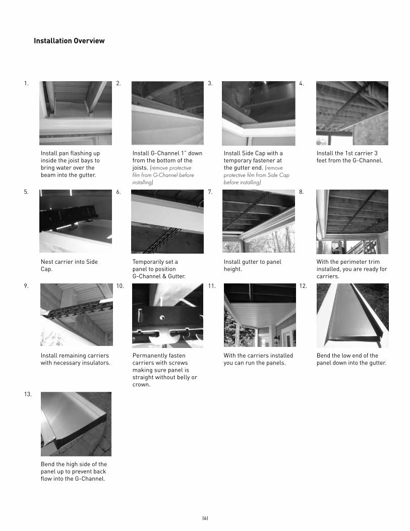
Install pan flashing up inside the joist bays to bring water over the beam into the gutter.
Install G-Channel 1” down from the bottom of the joists. (remove protective film from G-Channel before installing)
Install Side Cap with a temporary fastener at the gutter end. (remove protective film from Side Cap before installing)
Install the 1st carrier 3 feet from the G-Channel.
5. 6. 7. 8.
Nest carrier into Side Cap.
Temporarily set a panel to position G-Channel & Gutter.
Install gutter to panel height.
With the perimeter trim installed, you are ready for carriers.
9. 10. 11. 12.
Install remaining carriers with necessary insulators.
Permanently fasten carriers with screws making sure panel is straight without belly or crown.
With the carriers installed you can run the panels.
Bend the low end of the panel down into the gutter.
13.
Bend the high side of the panel up to prevent back flow into the G-Channel.
Installation Overview
(7)
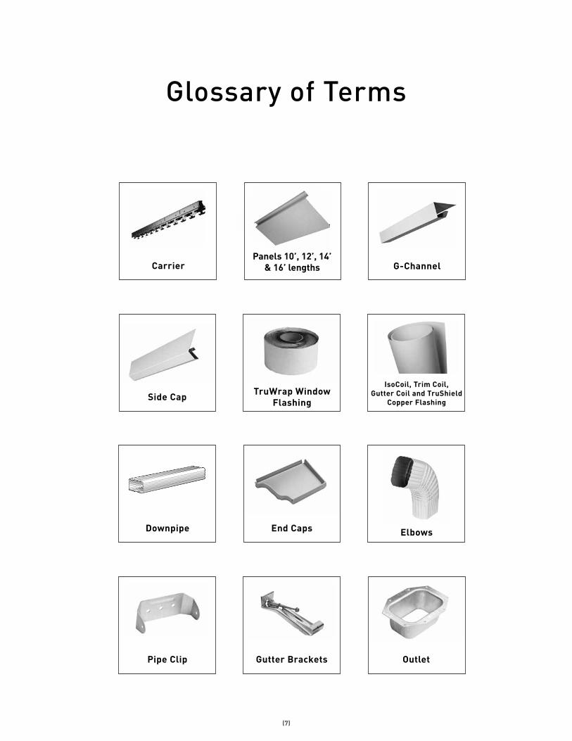
Side Cap TruWrap Window Flashing
IsoCoil, Trim Coil, Gutter Coil and TruShield
Copper Flashing
Downpipe End Caps Elbows
Pipe Clip Gutter Brackets Outlet
Glossary of Terms
Panels 10’, 12’, 14’ & 16’ lengths G-ChannelCarrier
(8)
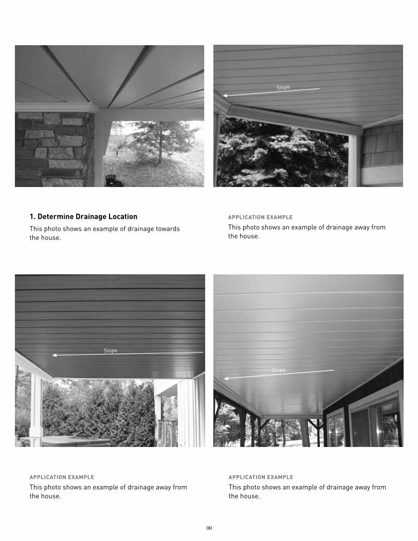
1. Determine Drainage Location
This photo shows an example of drainage towards the house.
APPLICATION EXAMPLE
This photo shows an example of drainage away from the house.
APPLICATION EXAMPLE
This photo shows an example of drainage away from the house.
APPLICATION EXAMPLE
This photo shows an example of drainage away from the house.
Slope
Slope
Slope
(9)
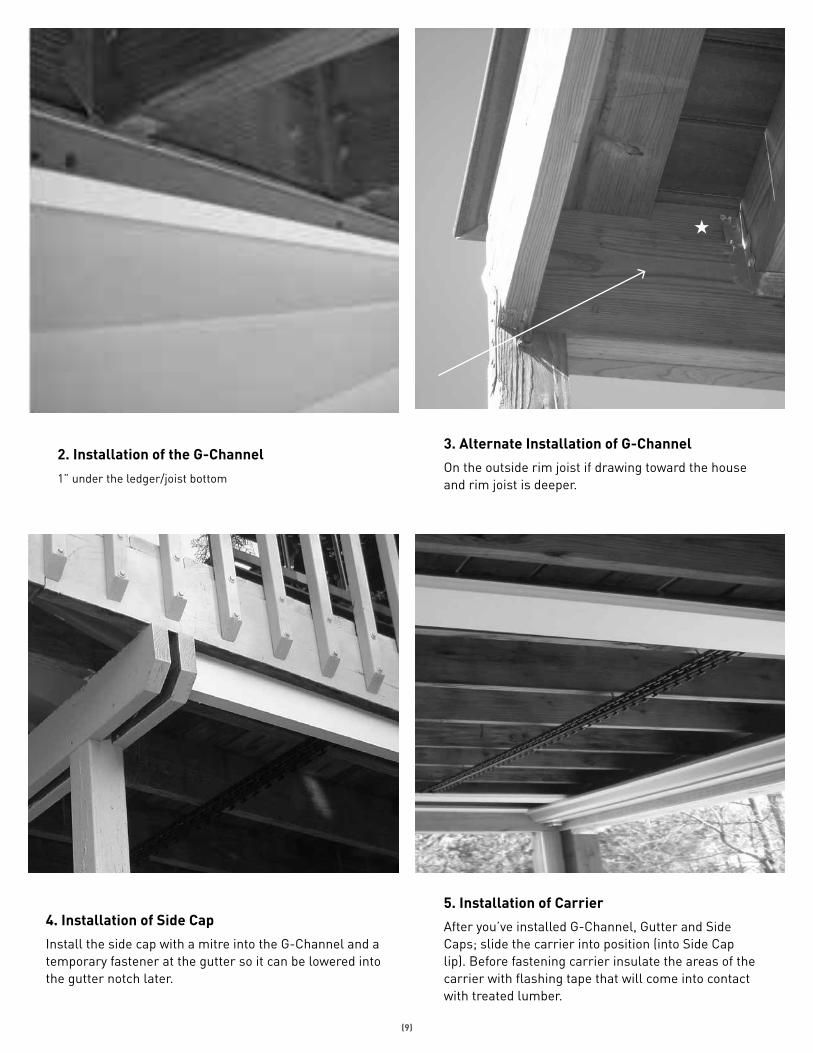
2. Installation of the G-Channel
1” under the ledger/joist bottom
3. Alternate Installation of G-Channel
On the outside rim joist if drawing toward the house and rim joist is deeper.
4. Installation of Side Cap
Install the side cap with a mitre into the G-Channel and a temporary fastener at the gutter so it can be lowered into the gutter notch later.
5. Installation of Carrier
After you’ve installed G-Channel, Gutter and Side Caps; slide the carrier into position (into Side Cap lip). Before fastening carrier insulate the areas of the carrier with flashing tape that will come into contact with treated lumber.

(10)
APPLICATION EXAMPLE
Carrier in position
Carriers should be 30” to 40” apart.
APPLICATION EXAMPLE
Carrier slides into side cap lip.
Bend the teeth of the carrier sideways so the first panel will nest into the side cap tightly.
APPLICATION EXAMPLE
Install window tape on the carrier where it makes contact with pressure treated lumber.
APPLICATION EXAMPLE
Fasten permanently by putting in a second screw on an angle to lock carrier elevation.
a.
a.
b.
(11)
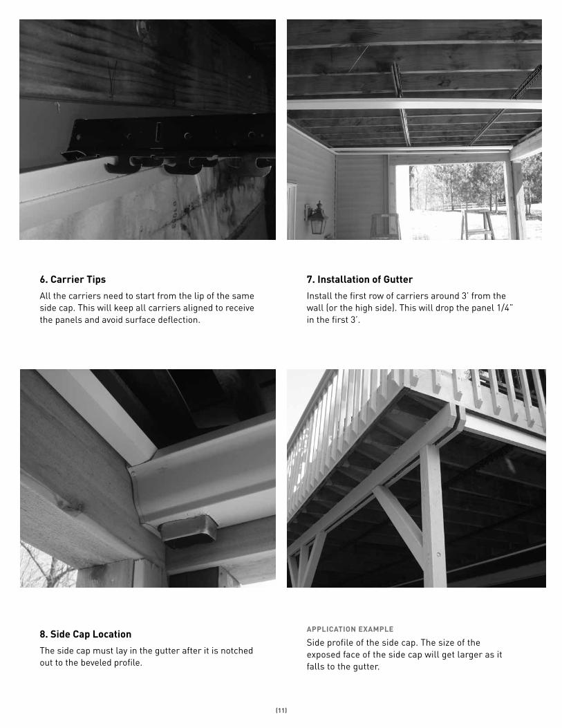
6. Carrier Tips
All the carriers need to start from the lip of the same side cap. This will keep all carriers aligned to receive the panels and avoid surface deflection.
7. Installation of Gutter
Install the first row of carriers around 3’ from the wall (or the high side). This will drop the panel 1/4” in the first 3’.
8. Side Cap Location
The side cap must lay in the gutter after it is notched out to the beveled profile.
APPLICATION EXAMPLE
Side profile of the side cap. The size of the exposed face of the side cap will get larger as it falls to the gutter.
(12)
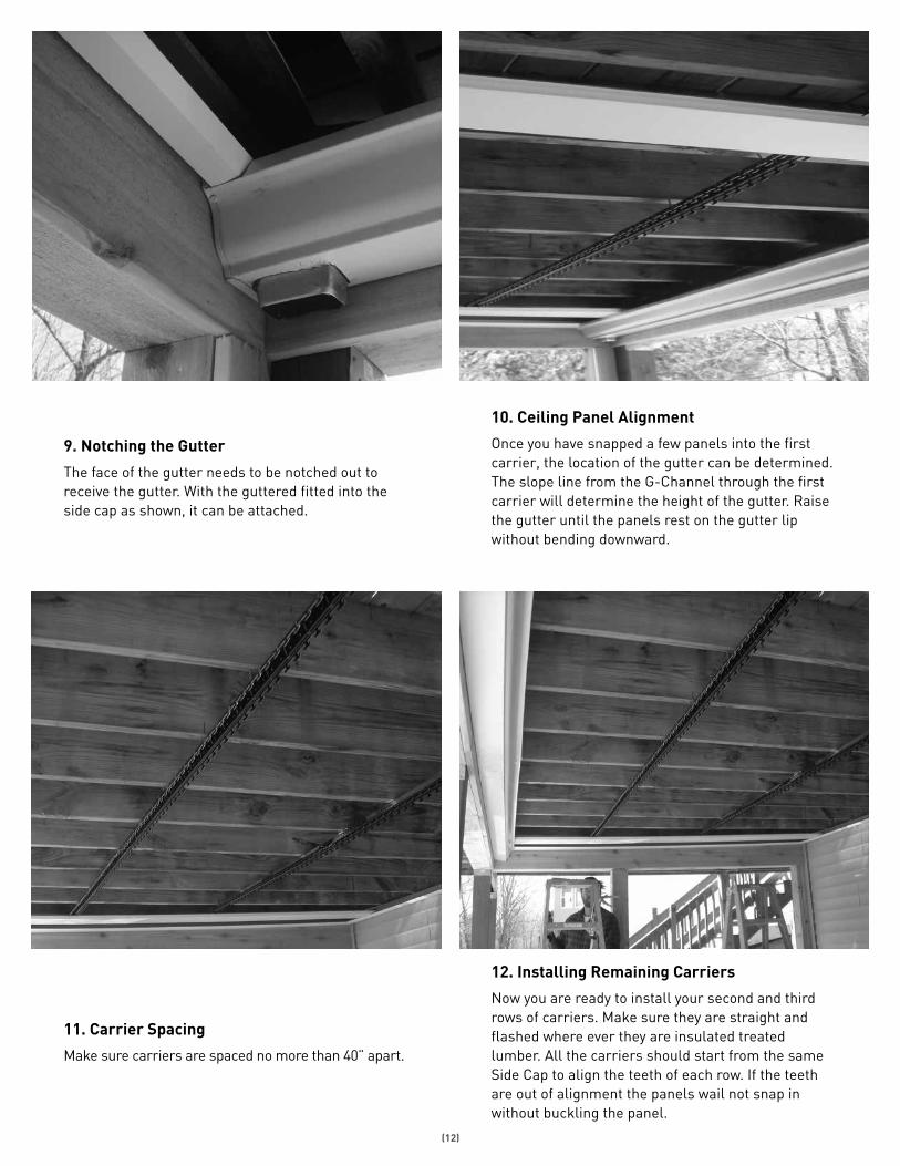
10. Ceiling Panel Alignment
Once you have snapped a few panels into the first carrier, the location of the gutter can be determined. The slope line from the G-Channel through the first carrier will determine the height of the gutter. Raise the gutter until the panels rest on the gutter lip without bending downward.
9. Notching the Gutter
The face of the gutter needs to be notched out to receive the gutter. With the guttered fitted into the side cap as shown, it can be attached.
11. Carrier Spacing
Make sure carriers are spaced no more than 40” apart.
12. Installing Remaining Carriers
Now you are ready to install your second and third rows of carriers. Make sure they are straight and flashed where ever they are insulated treated lumber. All the carriers should start from the same Side Cap to align the teeth of each row. If the teeth are out of alignment the panels wail not snap in without buckling the panel.
(13)
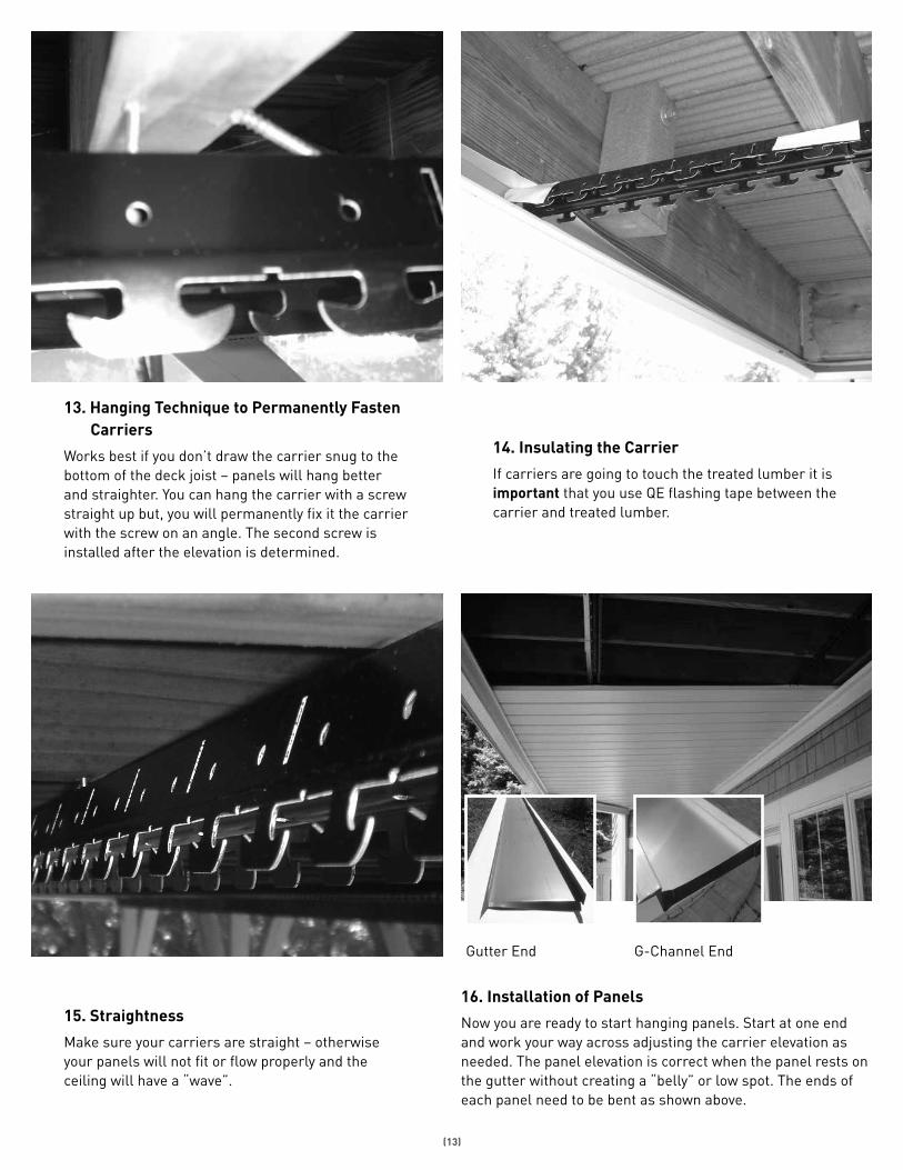
13. Hanging Technique to Permanently Fasten Carriers
Works best if you don’t draw the carrier snug to the bottom of the deck joist – panels will hang better and straighter. You can hang the carrier with a screw straight up but, you will permanently fix it the carrier with the screw on an angle. The second screw is installed after the elevation is determined.
14. Insulating the Carrier
If carriers are going to touch the treated lumber it is important that you use QE flashing tape between the carrier and treated lumber.
15. Straightness
Make sure your carriers are straight – otherwise your panels will not fit or flow properly and the ceiling will have a “wave”.
16. Installation of Panels
Now you are ready to start hanging panels. Start at one end and work your way across adjusting the carrier elevation as needed. The panel elevation is correct when the panel rests on the gutter without creating a “belly” or low spot. The ends of each panel need to be bent as shown above.
Gutter End G-Channel End
(14)
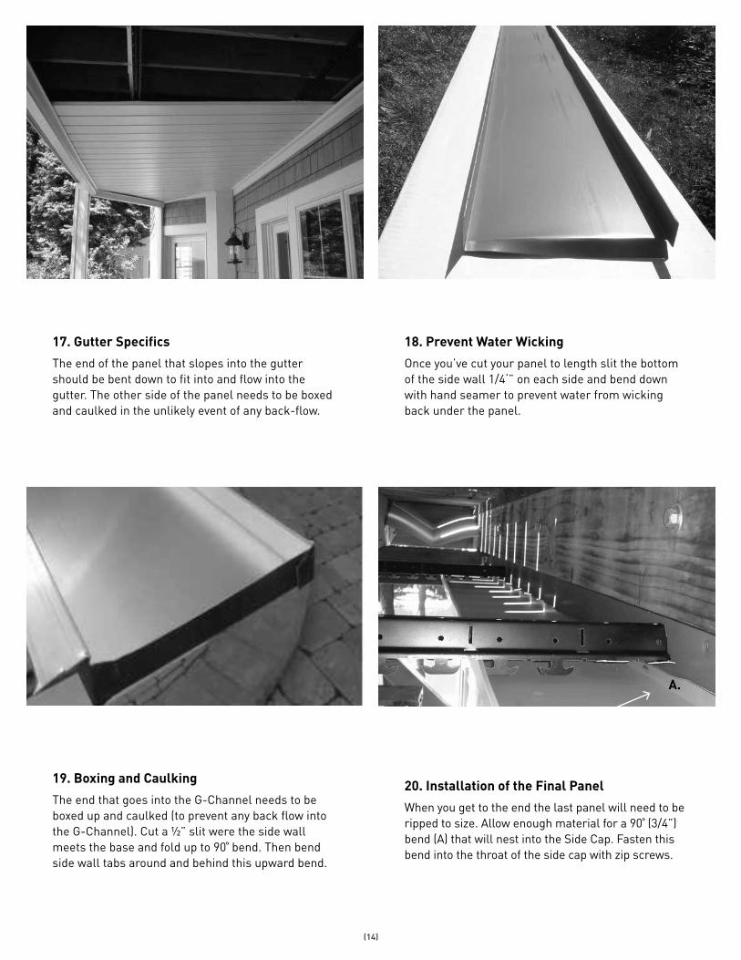
17. Gutter Specifics
The end of the panel that slopes into the gutter should be bent down to fit into and flow into the gutter. The other side of the panel needs to be boxed and caulked in the unlikely event of any back-flow.
18. Prevent Water Wicking
Once you’ve cut your panel to length slit the bottom of the side wall 1/4‘” on each side and bend down with hand seamer to prevent water from wicking back under the panel.
19. Boxing and Caulking
The end that goes into the G-Channel needs to be boxed up and caulked (to prevent any back flow into the G-Channel). Cut a ½” slit were the side wall meets the base and fold up to 90˚ bend. Then bend side wall tabs around and behind this upward bend.
20. Installation of the Final Panel
When you get to the end the last panel will need to be ripped to size. Allow enough material for a 90˚ (3/4”) bend (A) that will nest into the Side Cap. Fasten this bend into the throat of the side cap with zip screws.
A.
(15)
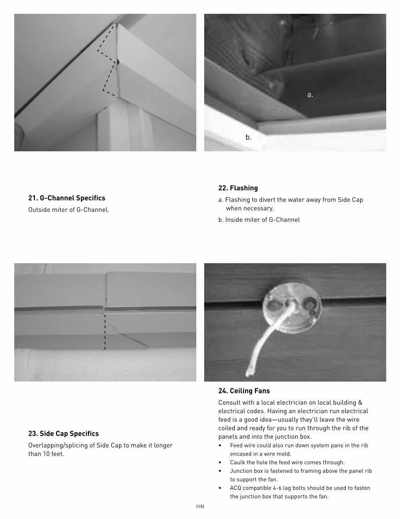
21. G-Channel Specifics
Outside miter of G-Channel.
22. Flashing
a. Flashing to divert the water away from Side Cap when necessary.
b. Inside miter of G-Channel
23. Side Cap Specifics
Overlapping/splicing of Side Cap to make it longer than 10 feet.
a.
b.
24. Ceiling Fans
Consult with a local electrician on local building & electrical codes. Having an electrician run electrical feed is a good idea—usually they’ll leave the wire coiled and ready for you to run through the rib of the panels and into the junction box.• Feed wire could also run down system pans in the rib
encased in a wire mold.• Caulk the hole the feed wire comes through.• Junction box is fastened to framing above the panel rib
to support the fan.• ACQ compatible 4-6 lag bolts should be used to fasten
the junction box that supports the fan.
(16)
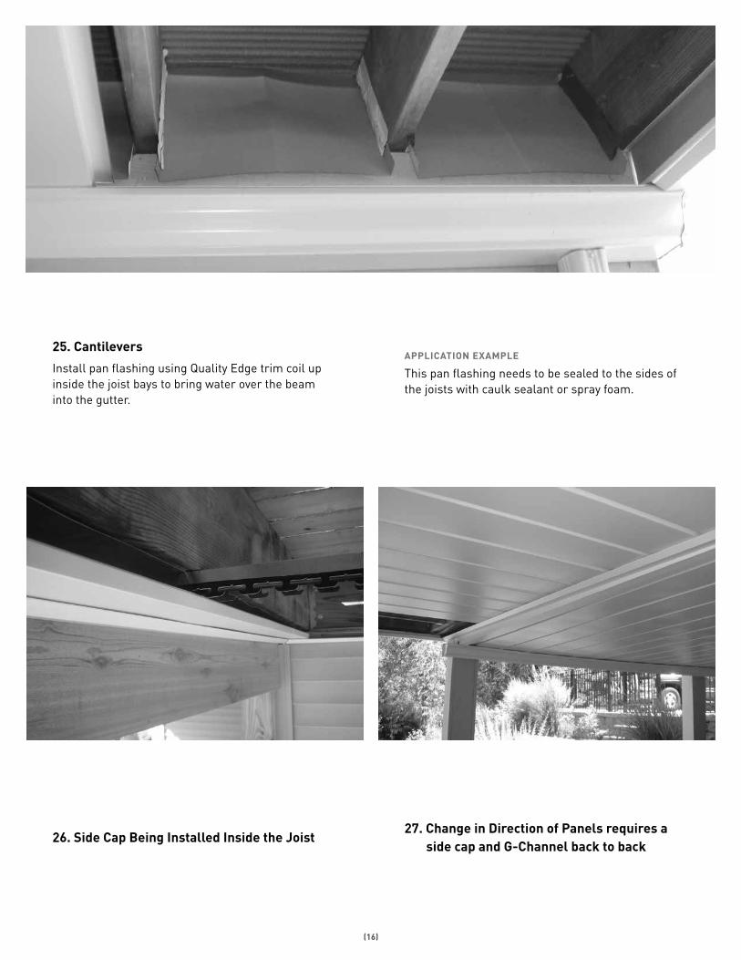
25. Cantilevers
Install pan flashing using Quality Edge trim coil up inside the joist bays to bring water over the beam into the gutter.
APPLICATION EXAMPLE
This pan flashing needs to be sealed to the sides of the joists with caulk sealant or spray foam.
26. Side Cap Being Installed Inside the Joist27. Change in Direction of Panels requires a
side cap and G-Channel back to back

(17)
28. Column Tips
Any panel the column penetrates needs to be flashed dry. In other words they cannot carry any water. This is achieved with a tent flashing running the full length of the panel.
APPLICATION EXAMPLE
Additional Column Applications
Columns that come to the system and get trimmed around need to be flashed dry.
29. Dry Vents
It is recommend that warm air vents be diverted down to direct hot air away from inside the system. Install a 90˚ elbow and flash above to keep this area dry. Then install the wall grill on the bottom of the panel to allow the warm air to escape.
30. Helpful Hint
Make sure the entire system is enclosed to keep the birds and pests out of the system.


insideoutunderdeck.comqualityedge.com
LAST
REV
ISED
11/
21/1
4