installation instructions and operating manual for
TRANSCRIPT

Page 1 of 39 ©WIH W:\MN-\MN-0027\MN-0027 (B-160) RevA 1-13-06.doc
14125 South Bridge Circle., Charlotte, NC 28273 USA • Tel: 704-716-7600 Fax: 704-295-9080 • www.wedecouv.com
Installation Instructions and
Operating Manual for
Ultraviolet Water Treatment System
Series B-160
-SEC-

Page 2 of 39 ©WIH W:\MN-\MN-0027\MN-0027 (B-160) RevA 1-13-06.doc
14125 South Bridge Circle., Charlotte, NC 28273 USA • Tel: 704-716-7600 Fax: 704-295-9080 • www.wedecouv.com
Table of Contents
1. INSTALLATION Before Mounting 4 Mounting of UV Chamber 4 Electrical Installation 6
2. START- UP Controller SEC 9 Switching on 10 Settings 12
3. OPERATION General 13 UV Lamp Monitoring System 14
4. MAINTENANCE
Cleaning Procedure 16 Replacement of UV Lamps 17 Disposal of used UV Lamps / Cleaning Agent Lime-A-Way 18 Replacement of Cooling Fan, Cleaning of Filter Mats 18 Check of UV Sensor during Operation 19 Ordering of Spare Parts 20
5. THRESHOLD VALUES 21 6. TROUBLE SHOOTING 22 7. ENCLOSURES: Installation Drawing Wiring Diagram Parts List Instruction “Cleaning Unit“ (if ordered)
Custom made project specific design of the delivered UV system and/or
additionally integrated components may result in non-conformity of the system to some instructions given in this manual. If this occurs, follow instruction only if they are clearly correct. If there are any questions regarding the conformity of your UV system to any instruction in this manual, contact WEDECO Ultraviolet Technologies or your representative for clarification. The numbers within this manual (marked: > ... <) are identical with those of the figure in chapter IVb) “Replacement of UV Lamps" and enclosed drawings.
Remark

Page 3 of 39 ©WIH W:\MN-\MN-0027\MN-0027 (B-160) RevA 1-13-06.doc
14125 South Bridge Circle., Charlotte, NC 28273 USA • Tel: 704-716-7600 Fax: 704-295-9080 • www.wedecouv.com
WEDECO ULTRAVIOLET TECHNOLOGIES ULTRAVIOLET INDUSTRIAL UNITS WEDECO Ultraviolet Technologies produces a variety of quality ultraviolet equipment to meet the needs of our industrial customers. We offer a simplified numbering system to better help our customers identify the unit that fits their requirements. EXAMPLE:
B120-U-EW-R-120-RF Series - Model Size –Chamber Configuration-Electric Wipe Option-Remote Option-Voltage supplied- Connection Options The numbering system for WEDECO Ultraviolet Technologies industrial units provides the series, model size, chamber configuration, a variety of options and voltage supplied by the customer. The model number begins by identifying the model as a member of the "B" or “LBA” series. The next section provides information on the model size. The numbers range from 15 to 400 depending on the dosage required. The letter(s) that follows describes the chamber configuration: "U" for chambers with inlet and outlet on the same side of the chamber and "Z" for inlet and outlets which are on opposite sides of the chamber. If an Electric Wiper is included then the letters “EW” follow. For systems where the enclosure needs to be more than 5m away from the chamber, an “R” is added. The voltage supplied is indicated next and lastly the connection is defined. RF for raised face flange, DN for DIN flanges and SN for sanitary fittings. Therefore, the B120-U-EW-R-120-RF label above identifies a B series unit, model 120, with a “U” type chamber configuration incorporating Electric Wiping and a remote enclosure that has 120v supplied to it. The chamber has raised face flanges for connection. Following is a chart indicating the sizes of connections for each model. Different connection sizes are not available due to chamber certification.
Model DIN Flange ANSI RF Flange Sanitary Fitting B40 DN150 6” 6” B60 DN150 6” 6” B80 DN150 6” 6” B120 DN200 8” 8” B160 DN200 8” 8” B220 DN250 10” 10” B300 DN300 12” 12” B400 DN300 12” 12”
LBA15 DN65 2 ½” 2 ½” LBA20 DN80 3” 3” LBA30 DN100 4” 4” LBA40 DN100 4” 4” LBA50 DN150 6” 6” LBA80 DN150 6” 6”
LBA110 DN150 6” 6” LBA150 DN200 8” 8” LBA200 DN200 8” 8”

Page 4 of 39 ©WIH W:\MN-\MN-0027\MN-0027 (B-160) RevA 1-13-06.doc
14125 South Bridge Circle., Charlotte, NC 28273 USA • Tel: 704-716-7600 Fax: 704-295-9080 • www.wedecouv.com
1. INSTALLATION
Before Mounting
Take care not to damage fragile components (UV Sensor, quartz jacket, UV lamp) during handling or installation!
Remove quartz sleeves only if it is absolutely necessary.
UV Chamber Installation Procedure Purpose To install UV chamber
Equipment required
Spanners Bolts, nuts, washers Lifting equipment with slings
1 Transport crate to mounting position.
2 Open lid and side plates.
3 Check the UV Chamber for any transport damage.
4 Check inside of UV chamber for any dirt, which may be present due to packaging. If necessary spray the inside of the UV chamber with clean water.
5 Install flexible pipe section to avoid mechanical tension on the UV chamber.
6 Install Inlet and Outlet isolation Valves.
7 Lift UV chamber in position with lifting eyes provided
8 Check required distances for maintenance purposes.
9 Insert UV chamber into existing pipe work.
10 Chamber to be levelled to within ± 1/16”
11 Connect Piping
12 Use EPDM seals, s/s bolts, nuts and washers to fix UV chamber to pipe work. Equally tighten bolts with torque spanner.
13 Check position of sampling valves, cleaning valve and air vent.
14 Insert UV lamps. Refer to section UV lamp Installation.
15 Fill UV chamber and pipe work with water and vent air thoroughly.
Procedure
16 Recycle all transport boxes.

Page 5 of 39 ©WIH W:\MN-\MN-0027\MN-0027 (B-160) RevA 1-13-06.doc
14125 South Bridge Circle., Charlotte, NC 28273 USA • Tel: 704-716-7600 Fax: 704-295-9080 • www.wedecouv.com
Take care not to damage fragile components like UV sensor, quartz sleeves and UV lamps during handling or installation! Ensure that the operational conditions, e.g. operating pressure, water quality, space, etc. meet the requirements. All piping must be fitted without mechanical tension. Freezing must be prevented. The chemical cleaning procedure of the UV chamber requires isolation valves at the UV chamber inlet and outlet. These valves should be installed directly at the flanges of the UV chamber to minimise the required volume of cleaning agent. For safety reasons, the UV lamps are shipped in separate transport boxes. Take care when handling s/s to prevent contamination with mild steel materials, dust and shavings. This can distort the protective oxide film and render it liable to pitting corrosion. Ensure that the UV chamber can be drained completely.
Operating periods ≥ 30 minutes without flow can cause excessive heat accumulation within the chamber. If combining an automatic shut-off valve with the UV system and/or other flow control devices, they must not stop the flow to cause heat accumulation. Pressure drop is about 1.5 – 7.3 PSI at nominal flow rate. Flow Direction – preferably upward (mandatory at gravity flow) as well as: Series B and Series LBA preferably towards module heads. To avoid quartz sleeve cracking, the UV Chamber must be isolated from pressure surges. Vent air thoroughly.
Wear safety boots.
Wear safety hat.
Safety
General Health and Safety Requirements. The UV lamps and quartz sleeves are fragile.
Page 6 of 39 ©WIH W:\MN-\MN-0027\MN-0027 (B-160) RevA 1-13-06.doc
14125 South Bridge Circle., Charlotte, NC 28273 USA • Tel: 704-716-7600 Fax: 704-295-9080 • www.wedecouv.com
UV lamps contain mercury. DO NOT PUT IN TRASH.
Recycle or dispose as hazardous waste. www.lamprecycle.org 1-866-457-6697
WARNING: This product contains a chemical known to the State of California to cause birth
defects or other reproductive harm.
Electrical Installation Avoid "dry running" of UV Chamber during function checks, respectively limit it to a maximum of 5 minutes. deposits on the quartz jackets should be removed before testing in order to avoid a "baking" effect. Purpose To install Electrical Cabinet
Equipment required
Spanners
Screwdrivers
Anchor bolts
Wire cutting pliers
Lifting equipment with slings
1 Transport crate to mounting position.
2 Open lid and side plates.
3 Check the Electrical Cabinet for any transport damage.
4 Lift Electrical Cabinet into position.
5 If required, fix Electrical Cabinet to the flooring. To do this, drill through holes located at the inside of plinth and fix with anchor bolts.
6 Install UV sensor cable between UV chamber and Electrical Cabinet.
7 Install lamp and control cables between UV chamber and Electrical Cabinet.
8 Install ground cable (PE, ≥ 4 mm²) between UV chamber and Electrical Cabinet.
9 Install customer interface cables to Electrical Cabinet.
10 Install mains supply cable to Electrical Cabinet.
Procedure
11 Recycle all transport boxes.

Page 7 of 39 ©WIH W:\MN-\MN-0027\MN-0027 (B-160) RevA 1-13-06.doc
14125 South Bridge Circle., Charlotte, NC 28273 USA • Tel: 704-716-7600 Fax: 704-295-9080 • www.wedecouv.com
Install all cables as short as possible. Install signal cables separate from power cables. Ensure that the operational conditions, e.g. power supply, room temperature, etc. meet the requirements. Install the Electrical Cabinet in a dry and cool place. Ensure appropriate protective safety systems are installed and operating (e.g. ground fault circuit breaker). Do not extend Lamp Cables or Sensor Cables or problems with UV lamp ignition and UV Intensity Monitoring may occur. When pulling cable, secure sensor plug so that it will not become disconnected. Electrical installation to be carried out according to relevant local standards and regulations. Refer to Electrical Schematics.
Risk of Electric Shock.
Wear safety hat.
Wear safety boots.
Safety
General Health and Safety Requirements.

Page 8 of 39 ©WIH W:\MN-\MN-0027\MN-0027 (B-160) RevA 1-13-06.doc
14125 South Bridge Circle., Charlotte, NC 28273 USA • Tel: 704-716-7600 Fax: 704-295-9080 • www.wedecouv.com
The electrical cabinet has terminals for:
Remote ON/OFF by a dry contact. To protect the UV lamps against high frequencies of switching it may be useful to install a additional off-delay timer (~30 minutes) for the UV system.
Signalling “NORMAL ON” This contact leaves rest position when the system is switched on with selector switch in position “NORMAL”. It may be combined with other contacts to avoid alarm signalling when the UV system is switched OFF. Signalling “System Running” This contact leaves rest position ~ 8 minutes after switching ON, this means ~ 3 minutes after the UV intensity is higher than the alarm threshold value*. Signalling “Low UV Intensity”
The contact leaves rest position when the UV intensity is lower than the pre-alert threshold value but higher than the alarm threshold value*. Signalling “System Failure” The contact is in rest position when the UV intensity is lower than the alarm threshold value* (or when a UV lamp fails). It is recommended to combine this contact with terminals “NORMAL ON”. *) See Section 5. “THRESHOLD VALUES"
Interlocking a pump or valve control circuit With too low UV intensity (or lamp failure) the control circuit of a pump or shut-off valve will be interlocked. As soon as “system running” is signalled, flow is allowed. Due to the integrated timer (~8 min.) the intensity will be stabilized before this happens. See also chapter III. “OPERATION“.
Signalling “cabinet high temperature” The contact leaves rest position when temperature inside is higher than 122°F. With “high temperature”, the UV lamps cannot be switched on. “Analog output 0/4-20 mA“ This signal at this terminal corresponds with the displayed UV Intensity. The load for external signal processing must not exceed 500 Ohm.
Page 9 of 39 ©WIH W:\MN-\MN-0027\MN-0027 (B-160) RevA 1-13-06.doc
14125 South Bridge Circle., Charlotte, NC 28273 USA • Tel: 704-716-7600 Fax: 704-295-9080 • www.wedecouv.com
2. START- UP
Controller SEC
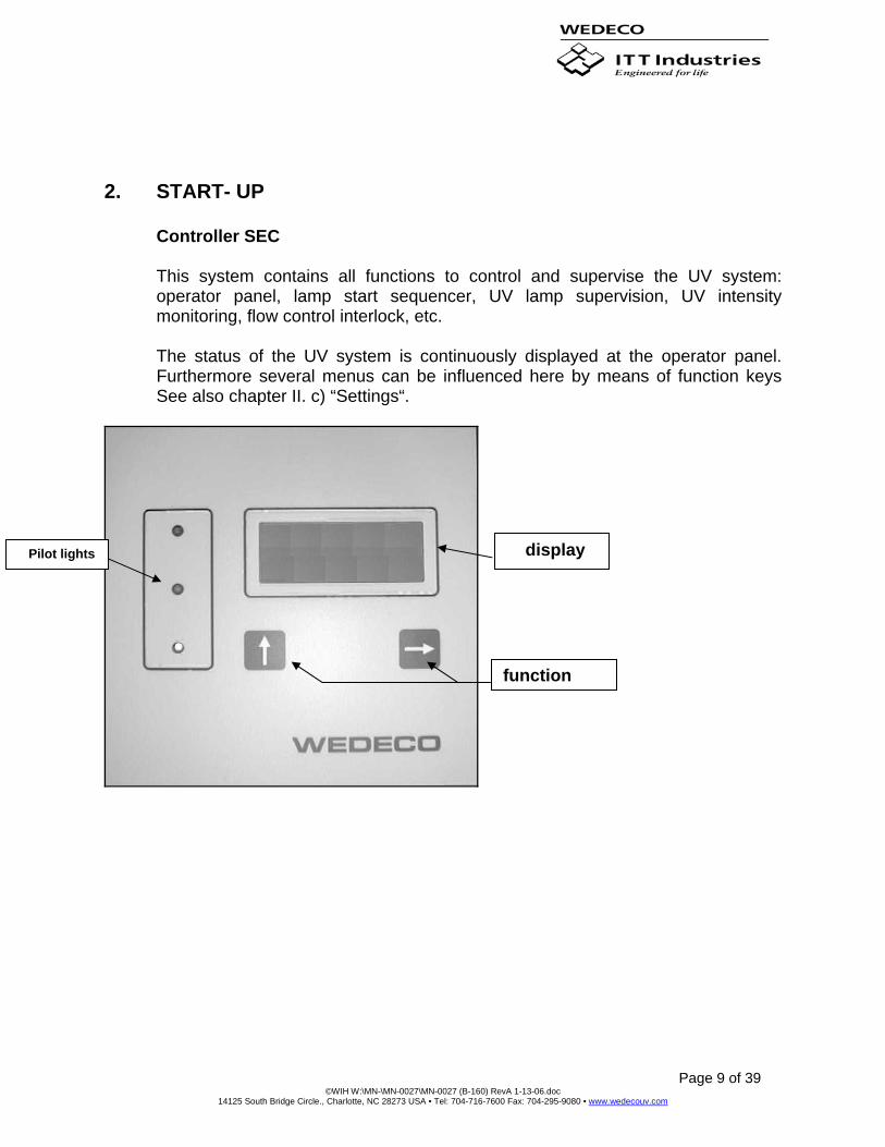
This system contains all functions to control and supervise the UV system: operator panel, lamp start sequencer, UV lamp supervision, UV intensity monitoring, flow control interlock, etc. The status of the UV system is continuously displayed at the operator panel. Furthermore several menus can be influenced here by means of function keys See also chapter II. c) “Settings“.
Pilot lights display
function

Page 10 of 39 ©WIH W:\MN-\MN-0027\MN-0027 (B-160) RevA 1-13-06.doc
14125 South Bridge Circle., Charlotte, NC 28273 USA • Tel: 704-716-7600 Fax: 704-295-9080 • www.wedecouv.com
Switching on Water hammer may damage the chamber if the complete system (chamber + piping) has not been thoroughly de- aerated. Also problems with the UV intensity monitoring system may occur !
Insert the separately packed UV lamps, if applicable. See Section 4 “Replacement of UV Lamps". Avoid “dry running“, then switch on: When the SEC controller is in operation, now the following messages will be displayed. If this does not happen or other questions/problems occur, please contact WEDECO Ultraviolet Technologies Service 704-716-7610 FAX 704-716-7601 As soon as >NEW SETTING ? / PRESS UP< is displayed, the following settings may be done (See section 2)
-reset of counter operational hours > UV lamps< -selection of analog output signal >UV intensity< (0-20mA or 4-20mA)
displayed message description
Preparation of UV system’s start-up phase, step 1:When switching on, the controller always will be checked automatically.
Preparation of UV system’s start-up phase, step 2: Now switch over to menu NEW SETTING is possible by function key ⇑ See also Section 2. If no settings are to be done, the start-up phase will be continued automatically after ~ 15 seconds.
This message appears if the selector switch is in position NORMAL and the remote command ON is missing. To continue the ON command is necessary or the selector switch has to be set to TEST.
This message appears if the temperature inside electrical cabinet is higher than 122°F. In this case the start-up phase will be stopped. continued on next page
WEDECO Ultraviolet Technologies AG
CONTROLLER SEC UV CONTROL
NEW SETTING ? PRESS UP
TEMPERATURE HIGH
WAIT FOR START UP
Page 11 of 39 ©WIH W:\MN-\MN-0027\MN-0027 (B-160) RevA 1-13-06.doc
14125 South Bridge Circle., Charlotte, NC 28273 USA • Tel: 704-716-7600 Fax: 704-295-9080 • www.wedecouv.com
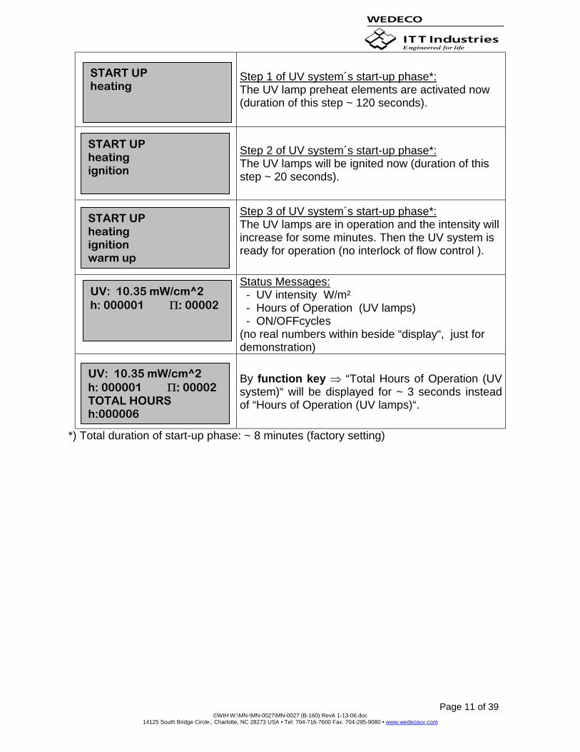
Step 1 of UV system´s start-up phase*: The UV lamp preheat elements are activated now (duration of this step ~ 120 seconds).
Step 2 of UV system´s start-up phase*: The UV lamps will be ignited now (duration of this step ~ 20 seconds).
Step 3 of UV system´s start-up phase*: The UV lamps are in operation and the intensity will increase for some minutes. Then the UV system is ready for operation (no interlock of flow control ).
Status Messages: - UV intensity W/m² - Hours of Operation (UV lamps) - ON/OFFcycles (no real numbers within beside “display“, just for demonstration)
By function key ⇒ “Total Hours of Operation (UV system)“ will be displayed for ~ 3 seconds instead of “Hours of Operation (UV lamps)“.
*) Total duration of start-up phase: ~ 8 minutes (factory setting)
START UP heating
START UP heating ignition
START UP heating ignition warm up
UV: 10.35 mW/cm^2 h: 000001 Π: 00002
UV: 10.35 mW/cm^2 h: 000001 Π: 00002 TOTAL HOURS h:000006

Page 12 of 39 ©WIH W:\MN-\MN-0027\MN-0027 (B-160) RevA 1-13-06.doc
14125 South Bridge Circle., Charlotte, NC 28273 USA • Tel: 704-716-7600 Fax: 704-295-9080 • www.wedecouv.com
Settings - selection of analog output signal >UV intensity< (0-20mA or 4-20mA) - reset of counter operational hours > UV lamps< - switch over to stand-by mode (for UV sensor check during normal operation) Therefore the UV system has to be switched ON first. When >NEW SETTING ? / PRESS UP< is displayed, proceed as described:
displayed message description
Press function key ⇑ ~ 1 second.
Set password 0 0 0 0* by pressing four times function key ⇒ .
After setting the password, it has to be confirmed bypressing function key ⇑ . Press function key ⇒ for corrections, and set password again if necessary.
Selection of analog output signal 0-20 mA = function key ⇒ 4-20 mA = function key ⇑
„Counter Operational Hours > UV lamps<: Reset (“0“) = function key ⇑ No reset = function key ⇒after this step the menu is closed.
NEW SETTING ? PRESS UP
PASSWORD: 0 * * * *
^ +1 cont.
PASSWORD: 8 0 0 0 0
FIGURES OK ? YES NO
RESET HOURS ? YES NO
SIGNAL CONVERTER 0–20 mA 4–20 mA

Page 13 of 39 ©WIH W:\MN-\MN-0027\MN-0027 (B-160) RevA 1-13-06.doc
14125 South Bridge Circle., Charlotte, NC 28273 USA • Tel: 704-716-7600 Fax: 704-295-9080 • www.wedecouv.com
3. OPERATION
General
The UV system normally is designed for water temperatures 41-140°F See order submittal and/or invoice.
The UV sensor is heat-proof up to 158°F continuously. Higher temperatures may occur within a few minutes if the UV lamps are switched on while the chamber is empty! The UV chamber may be included into hot CIP-cleaning or steam sterilization procedures up to 15 minutes, the UV system then must be switched off!!
After power supply failure the UV system re-starts automatically when mains returns.
Excessive on/off-switching (> 5/24h) as well as "dry running" will cause premature failure of the UV lamps (no claim for warranty).
The selector switch “TEST-NORMAL“ usually is in position NORMAL (especially if the UV system is combined with an automatically operated valve or pump):
Position Function
TEST
The UV system switches on without delay independent from remote control, the contact “interlock flow“ opens/stays open (flow interruption).
NORMAL
With remote “ON“ the UV system will be switched on without delay, the interlock contact switches on after UV intensity is higher than the threshold value for 3 minutes.With remote “OFF“ the UV system will be off without delay, the interlock contact switches off also without delay.
If the flow is interrupted, the UV system must be switched off (eventual manually) within 30 minutes. See chapter I. b) “Mounting ...“.
Lamp holders, plug connectors, as well as the electrical cabinet and the distribution box, if applicable, must always be tightly closed. They should be opened only for maintenance purposes with mains OFF.
TEMPERATURE HIGH will be signalled as soon as the cabinet’s internal temperature is higher than 122°F. See section 4. “TROUBLE SHOOTING“. With “high temperature” the UV system will not start running.
Page 14 of 39 ©WIH W:\MN-\MN-0027\MN-0027 (B-160) RevA 1-13-06.doc
14125 South Bridge Circle., Charlotte, NC 28273 USA • Tel: 704-716-7600 Fax: 704-295-9080 • www.wedecouv.com
UV Lamp Monitoring System
This system consists of UV sensor, electronics (amplifier/limit value relays), UV lamp supervision as well as operator panel with pilot lights, and text display. The intensity (254nm) within the chamber chamber is measured continuously by the UV sensor and is transferred as an analog signal to the electronics. After amplifying, it is displayed as [W/m2]. In addition, it is available as a standard analog output signal (0-20 or 4-20mA) for external signal processing.
The efficiency of the UV system substantially depends on the UV intensity inside the chamber. During operation, aging of the UV lamps reduces the UV intensity, as does scale formation. The intensity also may be influenced by supply voltage and/or UV absorption (water quality). Furthermore, alteration in water temperature or flow rate may be responsible for this. Also see chapter IV. “MAINTENANCE”.
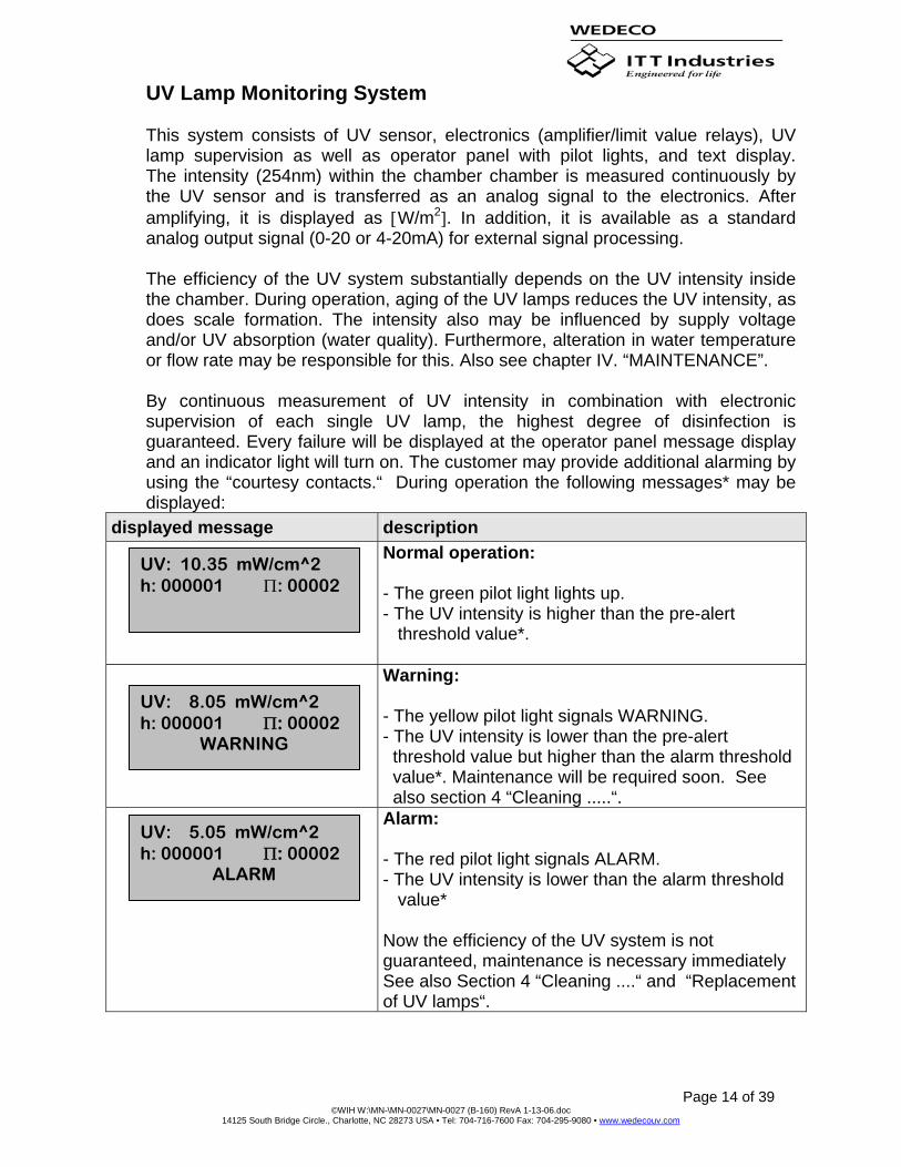
By continuous measurement of UV intensity in combination with electronic supervision of each single UV lamp, the highest degree of disinfection is guaranteed. Every failure will be displayed at the operator panel message display and an indicator light will turn on. The customer may provide additional alarming by using the “courtesy contacts.“ During operation the following messages* may be displayed:
displayed message description
Normal operation: - The green pilot light lights up. - The UV intensity is higher than the pre-alert threshold value*.
Warning: - The yellow pilot light signals WARNING. - The UV intensity is lower than the pre-alert threshold value but higher than the alarm threshold value*. Maintenance will be required soon. See also section 4 “Cleaning .....“.
Alarm: - The red pilot light signals ALARM. - The UV intensity is lower than the alarm threshold value* Now the efficiency of the UV system is not guaranteed, maintenance is necessary immediately See also Section 4 “Cleaning ....“ and “Replacement of UV lamps“.
UV: 10.35 mW/cm^2 h: 000001 Π: 00002
UV: 8.05 mW/cm^2 h: 000001 Π: 00002
WARNING
UV: 5.05 mW/cm^2 h: 000001 Π: 00002
ALARM
Page 15 of 39 ©WIH W:\MN-\MN-0027\MN-0027 (B-160) RevA 1-13-06.doc
14125 South Bridge Circle., Charlotte, NC 28273 USA • Tel: 704-716-7600 Fax: 704-295-9080 • www.wedecouv.com
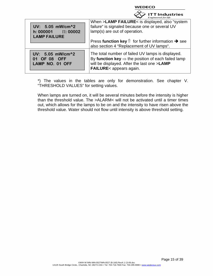
When >LAMP FAILURE< is displayed, also “system failure“ is signaled because one or several UV lamp(s) are out of operation. Press function key ⇑ for further information see also section 4 “Replacement of UV lamps“.
The total number of failed UV lamps is displayed. By function key ⇒ the position of each failed lamp will be displayed. After the last one >LAMP FAILURE< appears again.
*) The values in the tables are only for demonstration. See chapter V. “THRESHOLD VALUES” for setting values. When lamps are turned on, it will be several minutes before the intensity is higher than the threshold value. The >ALARM< will not be activated until a timer times out, which allows for the lamps to be on and the intensity to have risen above the threshold value. Water should not flow until intensity is above threshold setting.
UV: 5.05 mW/cm^2 01 OF 08 OFF LAMP NO. 01 OFF
UV: 5.05 mW/cm^2 h: 000001 Π: 00002 LAMP FAILURE

Page 16 of 39 ©WIH W:\MN-\MN-0027\MN-0027 (B-160) RevA 1-13-06.doc
14125 South Bridge Circle., Charlotte, NC 28273 USA • Tel: 704-716-7600 Fax: 704-295-9080 • www.wedecouv.com
4. MAINTENANCE Cleaning Procedure
(normally not required within de-ionized water systems)
A cleaning procedure should be carried out as often as scale causes a decrease in UV intensity of ~ 20% ( when >WARNING< is displayed). An intensity decrease may also be caused by aging of the UV lamps or changes in water quality (UV transmission). A visual inspection is helpful before starting the cleaning procedure:
Dismount the sensor tube (including UV sensor) and/or one complete UV module. Wipe it/them off with a soft white cloth. When re-installing the sensor tube, screw it only by hand. If it leaks, use a wrench (23mm) to twist it for about 10°. Proceeding in this way leads to cleaning intervals, which are adapted to the individual operating conditions (water quality).
The UV module (assembly group) mainly consists of: quartz module, lamp holder and UV lamp (See figure in section 4 “Replacement of UV Lamps”). For dismounting no special tools are required:
• Close shut-off valves slowly at inlet and outlet, then switch off mains. • Discharge chamber or release pressure. • Disconnect module cable (plug) and loosen screws. • Carefully pull off complete UV module from the chamber (when re-
assembling check o-ring for injury and correct position). Each module is centered by a TEFLON spacer which is located inside the chamber about 1.18” from module‘s end. Due to this there is some resistance when installing/re-installing the module.
To remove scale caused by dissolved minerals (calcium, etc.), flushing with a cleaning agent based upon phosphoric acid or citric acid or similar acids is recommended. Usually, the cleaning agent will be used none diluted (components in chamber are highly resistant against these chemicals). Alternatively an external cleaning of UV modules and sensor tube is possible, this cleaning procedure is similar as described beneath.
We recommend using Lime-A-Way, which is based upon phosphoric acid (> 25%). For dilution of Lime-A-Way the required quantity of concentrate will be at least 20% of the chamber volume, chamber volume see nameplate.
Page 17 of 39 ©WIH W:\MN-\MN-0027\MN-0027 (B-160) RevA 1-13-06.doc
14125 South Bridge Circle., Charlotte, NC 28273 USA • Tel: 704-716-7600 Fax: 704-295-9080 • www.wedecouv.com
Protect eyes, skin and clothes when handling cleaning agent. Splashes must be washed away immediately. Furthermore, the usual safety regulations must be observed!
Replacement of UV Lamps
The effective life of the UV lamps depends on the required minimum UV dose [J/m2] which is resulting from the existing UV intensity [W/m2] as well as the individual operating parameters (flow rate, UV transmission). The lamps have to be replaced when the required water quality is not obtained with the available UV intensity. This may be earlier or later than indicated by the UV Lamp Monitoring System. For general orientation: Due to ageing, decrease in UV intensity of ~50% occurs after about 8,-10,000 hours of operation.
If a UV lamp near to the UV sensor fails, it must be replaced by a “working“ lamp of the same chamber. By this, wrong UV intensity monitoring is avoided as new lamps in this position will generate too high intensity values.
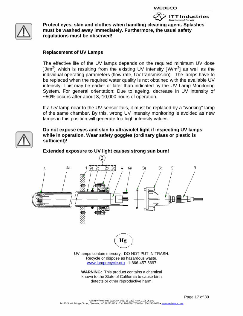
Do not expose eyes and skin to ultraviolet light if inspecting UV lamps while in operation. Wear safety goggles (ordinary glass or plastic is sufficient)!
Extended exposure to UV light causes strong sun burn!
4a
UV lamps contain mercury. DO NOT PUT IN TRASH.
Recycle or dispose as hazardous waste. www.lamprecycle.org 1-866-457-6697
WARNING: This product contains a chemical known to the State of California to cause birth
defects or other reproductive harm.
Page 18 of 39 ©WIH W:\MN-\MN-0027\MN-0027 (B-160) RevA 1-13-06.doc
14125 South Bridge Circle., Charlotte, NC 28273 USA • Tel: 704-716-7600 Fax: 704-295-9080 • www.wedecouv.com
Close shut-off valves at inlet or outlet, then switch off. Disconnect module cable (plug) >3< and loosen screws >5b<.
UV lamps may be hot, hold them at both ends when handling, otherwise risk of breaking!
Carefully pull off complete “lamp assembly“ (UV lamp >4< including lamp holder >5< and socket >6<) out of the chamber (quartz module >2< which is consisting of item 2a + 2c). Put “lamp assembly“ on a table and pull pin contacts >6a< from lamp holder (by means of a pair of pointed pliers). Then remove lamp holder as well as socket from UV lamp. Inspect quartz module inside and clean it, if necessary (e.g. soft cloth wetted with denatured alcohol). Therefore dismounting of the quartz module is helpful. See also Section 4 “Cleaning Procedure“.
De-pressurize chamber before dismounting a quartz module! A cracked quartz module must be replaced immediately to avoid breakage (leakage)! When inserting a new UV lamp, take care that no fingerprints are left on lamp, clean it with denatured alcohol, if necessary!
Before re-assembly, check O-rings >5a< and >2d< for injury/correct position. If necessary, lubricate O-rings with a thin film of Vaseline to improve sealing effect. Carefully insert new UV lamps by applying above instructions in reverse order (the amalgam >4a< should be upside, if applicable), but do not tighten lamp holder. Check functioning of new lamps by switching on for a few seconds (wear safety goggles !), then tighten screws >5b<. Finally re-start UV system and reset hours counter, if applicable. See Section 2) “Settings“.
Disposal of used UV Lamps / Lime-A-Way
UV lamps must be disposed of in the same way as traditional fluorescent lamps, as they contain small quantities of mercury (amalgam). They are special waste and must be returned unbroken to the respective collecting depot or to WEDECO Ultraviolet Technologies.
Lime-A-Way is non-toxic and biologically degradable, there is no need for special disposal.
Replacement of Cooling Fan, Cleaning of Filter Mats
The fan in the electrical cabinet should be replaced after 30,000 hours of operation. The filter mats of the fan (air inlet and outlet) should be washed/replaced when “cabinet high temperature” is signalled.
Page 19 of 39 ©WIH W:\MN-\MN-0027\MN-0027 (B-160) RevA 1-13-06.doc
14125 South Bridge Circle., Charlotte, NC 28273 USA • Tel: 704-716-7600 Fax: 704-295-9080 • www.wedecouv.com
Check of UV sensor during Operation
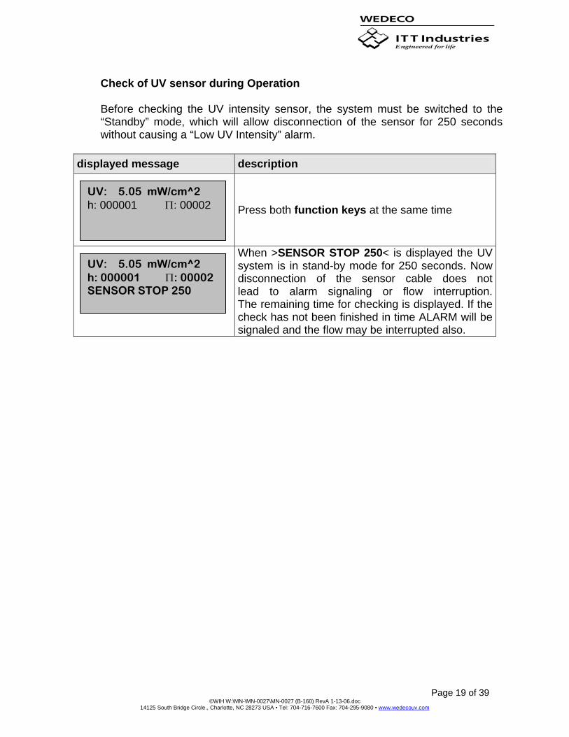
Before checking the UV intensity sensor, the system must be switched to the “Standby” mode, which will allow disconnection of the sensor for 250 seconds without causing a “Low UV Intensity” alarm.
displayed message description
Press both function keys at the same time
When >SENSOR STOP 250< is displayed the UV system is in stand-by mode for 250 seconds. Now disconnection of the sensor cable does not lead to alarm signaling or flow interruption.The remaining time for checking is displayed. If the check has not been finished in time ALARM will be signaled and the flow may be interrupted also.
UV: 5.05 mW/cm^2 h: 000001 Π: 00002
UV: 5.05 mW/cm^2 h: 000001 Π: 00002 SENSOR STOP 250
Page 20 of 39 ©WIH W:\MN-\MN-0027\MN-0027 (B-160) RevA 1-13-06.doc
14125 South Bridge Circle., Charlotte, NC 28273 USA • Tel: 704-716-7600 Fax: 704-295-9080 • www.wedecouv.com
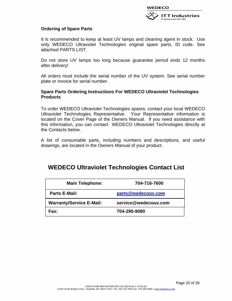
Ordering of Spare Parts
It is recommended to keep at least UV lamps and cleaning agent in stock. Use only WEDECO Ultraviolet Technologies original spare parts, ID code. See attached PARTS LIST.
Do not store UV lamps too long because guarantee period ends 12 months after delivery! All orders must include the serial number of the UV system. See serial number plate or invoice for serial number.
Spare Parts Ordering Instructions For WEDECO Ultraviolet Technologies Products
To order WEDECO Ultraviolet Technologies spares, contact your local WEDECO Ultraviolet Technologies Representative. Your Representative information is located on the Cover Page of the Owners Manual. If you need assistance with this information, you can contact WEDECO Ultraviolet Technologies directly at the Contacts below.
A list of consumable parts, including numbers and descriptions, and useful drawings, are located in the Owners Manual of your product.
WEDECO Ultraviolet Technologies Contact List
Parts E-Mail: [email protected]
Warranty/Service E-Mail: [email protected]
Main Telephone: 704-716-7600
Fax: 704-295-9080
Page 21 of 39 ©WIH W:\MN-\MN-0027\MN-0027 (B-160) RevA 1-13-06.doc
14125 South Bridge Circle., Charlotte, NC 28273 USA • Tel: 704-716-7600 Fax: 704-295-9080 • www.wedecouv.com
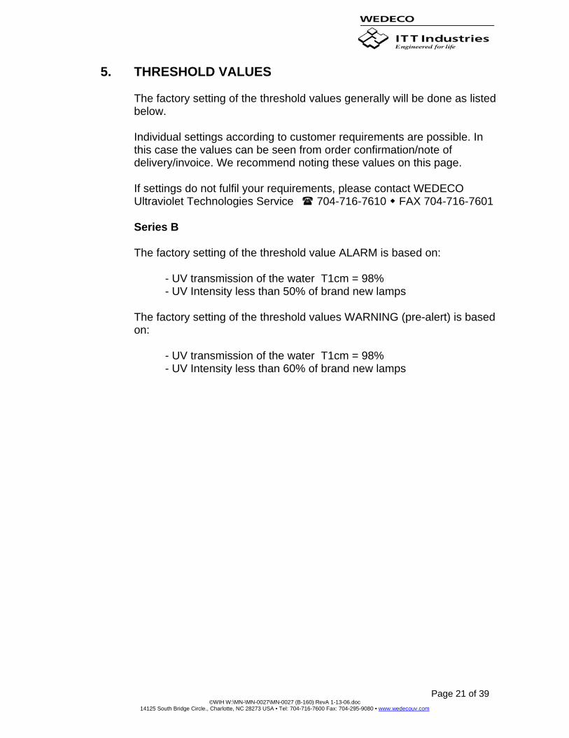
5. THRESHOLD VALUES
The factory setting of the threshold values generally will be done as listed below. Individual settings according to customer requirements are possible. In this case the values can be seen from order confirmation/note of delivery/invoice. We recommend noting these values on this page. If settings do not fulfil your requirements, please contact WEDECO Ultraviolet Technologies Service 704-716-7610 FAX 704-716-7601 Series B The factory setting of the threshold value ALARM is based on: - UV transmission of the water T1cm = 98% - UV Intensity less than 50% of brand new lamps The factory setting of the threshold values WARNING (pre-alert) is based on: - UV transmission of the water T1cm = 98% - UV Intensity less than 60% of brand new lamps

Page 22 of 39 ©WIH W:\MN-\MN-0027\MN-0027 (B-160) RevA 1-13-06.doc
14125 South Bridge Circle., Charlotte, NC 28273 USA • Tel: 704-716-7600 Fax: 704-295-9080 • www.wedecouv.com
6. TROUBLE SHOOTING SWITCH OFF MAINS BEFORE WORKING AT ELECTRICAL EQUIPMENT!
Problem Possible reason
No function while selector switch in position TEST
No mains (supply) voltage. Circuit breaker off.
Yellow or red pilot light lights up
UV sensor cable (plug) interrupted/defective. UV sensor defective. UV lamp(s) not inserted or not ignited.
UV lamp(s) do(es) not ignite UV lamp defective (quartz broken, electrodes interrupted, etc.) or over aged or too high on/off frequency. Faulty contact (plug connector, socket, etc.). Lamp devices (ballast, igniters, transformer, etc.) defective. Mains (supply) voltage less than 200 volts. Water temperature too low.
UV intensity too low UV absorption too high (bad water quality). UV lamps reached “end of life“. Cleaning procedure necessary. Moisture or dust inside quartz module. UV sensor or sensor tube faulty.
UV meter reacts “confused“ Air bubbles within water. Analog output signal overloaded. Mains voltage or water quality (UV absorption) permanently altering. Sensor signal or electronics influenced by a strong external source of interference (frequency converter “oldtimer“, devices with pulse current, etc.).
>TEMPERATURE HIGH< is displayed
Room temperature more than 104°F. Filter mats have to be cleaned. Fan or thermal switch defective.
SEC CONTROL OUTPUTS
• K1 contactor- controls (on/off) the voltage across the lamp • K2 contactor- controls (on/off) the voltage across the filaments • K3 relay- system failure, should be energized without a failure • K4 relay- system running, energizes after the start up is complete • K5 relay- cabinet high temp. should be energized when the system is cool
enough to operate • K6 relay- system normal, should be energized when the system is in
normal mode
Page 23 of 39 ©WIH W:\MN-\MN-0027\MN-0027 (B-160) RevA 1-13-06.doc
14125 South Bridge Circle., Charlotte, NC 28273 USA • Tel: 704-716-7600 Fax: 704-295-9080 • www.wedecouv.com
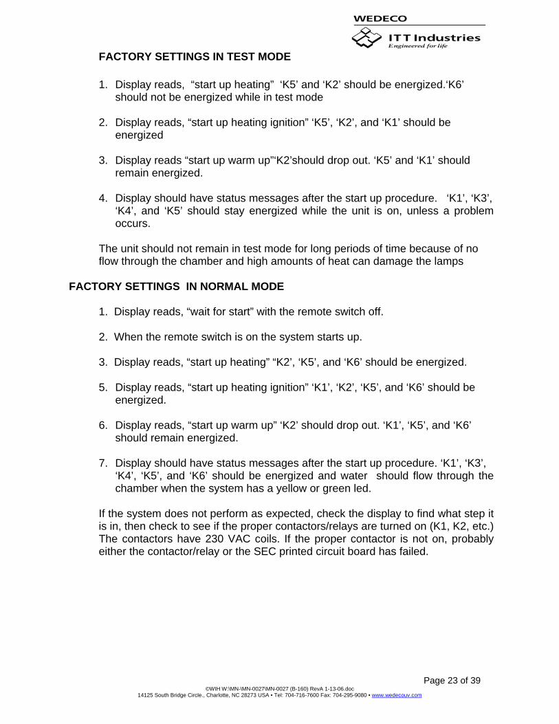
FACTORY SETTINGS IN TEST MODE
1. Display reads, “start up heating” ‘K5’ and ‘K2’ should be energized.‘K6’ should not be energized while in test mode
2. Display reads, “start up heating ignition” ‘K5’, ‘K2’, and ‘K1’ should be
energized
3. Display reads “start up warm up”‘K2’should drop out. ‘K5’ and ‘K1’ should remain energized.
4. Display should have status messages after the start up procedure. ‘K1’, ‘K3’,
‘K4’, and ‘K5’ should stay energized while the unit is on, unless a problem occurs.
The unit should not remain in test mode for long periods of time because of no flow through the chamber and high amounts of heat can damage the lamps
FACTORY SETTINGS IN NORMAL MODE
1. Display reads, “wait for start” with the remote switch off.
2. When the remote switch is on the system starts up.
3. Display reads, “start up heating” “K2’, ‘K5’, and ‘K6’ should be energized.
5. Display reads, “start up heating ignition” ‘K1’, ‘K2’, ‘K5’, and ‘K6’ should be energized.
6. Display reads, “start up warm up” ‘K2’ should drop out. ‘K1’, ‘K5’, and ‘K6’
should remain energized.
7. Display should have status messages after the start up procedure. ‘K1’, ‘K3’, ‘K4’, ‘K5’, and ‘K6’ should be energized and water should flow through the chamber when the system has a yellow or green led.
If the system does not perform as expected, check the display to find what step it is in, then check to see if the proper contactors/relays are turned on (K1, K2, etc.) The contactors have 230 VAC coils. If the proper contactor is not on, probably either the contactor/relay or the SEC printed circuit board has failed.
Page 24 of 39 ©WIH W:\MN-\MN-0027\MN-0027 (B-160) RevA 1-13-06.doc
14125 South Bridge Circle., Charlotte, NC 28273 USA • Tel: 704-716-7600 Fax: 704-295-9080 • www.wedecouv.com
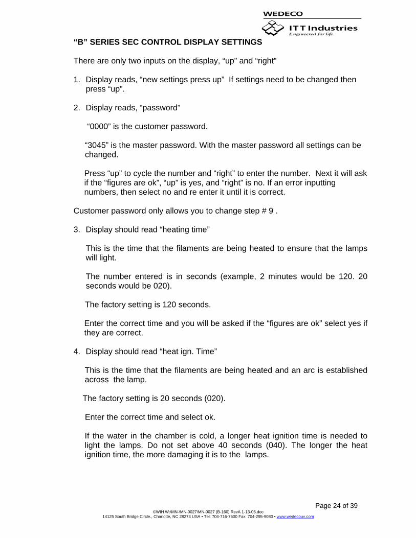
“B” SERIES SEC CONTROL DISPLAY SETTINGS
There are only two inputs on the display, “up” and “right”
1. Display reads, “new settings press up” If settings need to be changed then press “up”.
2. Display reads, “password”
“0000” is the customer password.
“3045” is the master password. With the master password all settings can be changed.
Press “up” to cycle the number and “right” to enter the number. Next it will ask if the “figures are ok”, “up” is yes, and “right” is no. If an error inputting numbers, then select no and re enter it until it is correct.
Customer password only allows you to change step # 9 .
3. Display should read “heating time”
This is the time that the filaments are being heated to ensure that the lamps will light. The number entered is in seconds (example, 2 minutes would be 120. 20 seconds would be 020).
The factory setting is 120 seconds.
Enter the correct time and you will be asked if the “figures are ok” select yes if they are correct.
4. Display should read “heat ign. Time”
This is the time that the filaments are being heated and an arc is established across the lamp.
The factory setting is 20 seconds (020).
Enter the correct time and select ok.
If the water in the chamber is cold, a longer heat ignition time is needed to light the lamps. Do not set above 40 seconds (040). The longer the heat ignition time, the more damaging it is to the lamps.

Page 25 of 39 ©WIH W:\MN-\MN-0027\MN-0027 (B-160) RevA 1-13-06.doc
14125 South Bridge Circle., Charlotte, NC 28273 USA • Tel: 704-716-7600 Fax: 704-295-9080 • www.wedecouv.com
5. Display should read, “warm up time” This is the time it takes for the lamps to warm up to have a high enough kill level before water is allowed to pass through the chamber.
The factory setting is 180 seconds.
Enter the correct time and select ok.
5. Display should read “warning level”
This is the level of intensity that will give you a yellow warning, which means the chamber needs to be cleaned.
The factory setting is 70%. The unit must be run in test mode at least once to determine the level of intensity (example, if the intensity level is 120W/m2, then 70% would be 084).
Enter the actual number (not percentage), and if its ok, select yes.
Every time the chamber is cleaned, the number will have to be changed so that when the lamps age you do not get a yellow warning.
6. Display should read “alarm level”
This is the level of intensity that will give a red alarm and shut off the flow to the chamber.
The factory setting is 50% like the warning level.
The unit must be run to determine the level of intensity (example, 120W/m2 would be 060). Enter the actual number (not percentage), and if it’s ok, select yes. 7. Display should read “nr of lamps”
This is the number of lamps that is in the system. Up to 64 is allowed per one SEC board (if there are more than 64 lamps, then another SEC board is needed) Enter the number of lamps (5 lamps would be 05), if it’s ok, select yes.
Page 26 of 39 ©WIH W:\MN-\MN-0027\MN-0027 (B-160) RevA 1-13-06.doc
14125 South Bridge Circle., Charlotte, NC 28273 USA • Tel: 704-716-7600 Fax: 704-295-9080 • www.wedecouv.com
8. Display should read “stromausgang/ma”
This is a German description for the UV intensity selection. It’s nothing more than selecting “0-20mA” or “4-20mA” for the SEC output for “UV” intensity. “0-20mA” is the “up” key, and “4-20mA” is the “right key”
9. Display should read, “reset hours”
This resets the hour meter on the display. Every time the lamps are changed, the hours should be reset. “up” for yes, and “right” for no.
If there are any questions or problems your can not solve, do not hesitate to contact WEDECO Ultraviolet Technologies 704-716-7600 FAX 704-295-9080

Page 27 of 39 ©WIH W:\MN-\MN-0027\MN-0027 (B-160) RevA 1-13-06.doc
14125 South Bridge Circle., Charlotte, NC 28273 USA • Tel: 704-716-7600 Fax: 704-295-9080 • www.wedecouv.com
MS UV DISINFECTION SYSTEM
THIS DRAWING CONTAINS DESIGNS AND OTHER INFORMATION WHICH ARE THE PROPERTY OF WEDECO-IDEAL HORIZONS, INC. EXCEPT FOR RIGHTS EXPRESSLY
GRANTED BY CONTRACT TO THE UNITED STATES GOVERNMENT. THIS DRAWING MAY NOT, IN WHOLE OR IN PART, BE DUPLICATED OR DISCLOSED OR USED FOR
MANUFACTURE OF THE PART DISCLOSED HEREIN, WITHOUT THE PRIOR WRITTEN PERMISSION OF WEDECO-IDEAL HORIZONS, INC.
B1 OF 1
GA-1001
UV REACTOR
B160
NOTES:
1. ALL DIMENSIONS ARE ±1/4" UNLESS STATED OTHERWISE.
2. ALL WETTED PARTS SHALL HAVE FULL PENETRATION FUSION WELDS.
3. CABLES TO UV SYSTEM ENCLOSURE TO BE 15' LONG.
56 " SERVICEAREA REQUIRED
37 5/16 "
Ø40 9/16 "
Ø50 7/8 "
1/4" SAMPLE VALVEUV SENSOR
8" RFF
LAMP CABLE
LAMP CONNECTOR1/2" NPT BALL DRAIN VALVE
174 9/16 "
128 3/4 "
Page 28 of 39 ©WIH W:\MN-\MN-0027\MN-0027 (B-160) RevA 1-13-06.doc
14125 South Bridge Circle., Charlotte, NC 28273 USA • Tel: 704-716-7600 Fax: 704-295-9080 • www.wedecouv.com
RPRP
STANDARD PRODUCT
JJJJ B
11
-1
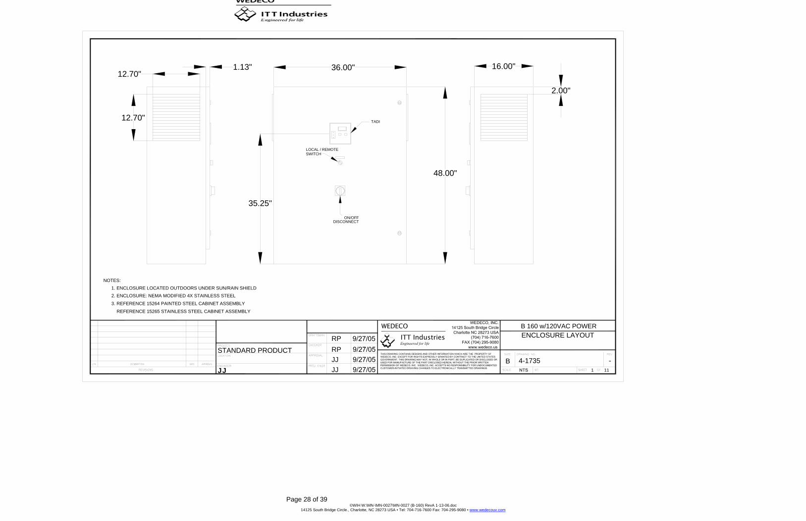
B 160 w/120VAC POWERENCLOSURE LAYOUT
4-1735JJ
36.00"
35.25"
REFERENCE 15265 STAINLESS STEEL CABINET ASSEMBLY
3. REFERENCE 15264 PAINTED STEEL CABINET ASSEMBLY
2. ENCLOSURE: NEMA MODIFIED 4X STAINLESS STEEL1. ENCLOSURE LOCATED OUTDOORS UNDER SUN/RAIN SHIELD
NOTES:
12.70"1.13"
12.70"
48.00"
16.00"
2.00"
DISCONNECTON/OFF
LOCAL / REMOTESWITCH
TADI

Page 29 of 39 ©WIH W:\MN-\MN-0027\MN-0027 (B-160) RevA 1-13-06.doc
14125 South Bridge Circle., Charlotte, NC 28273 USA • Tel: 704-716-7600 Fax: 704-295-9080 • www.wedecouv.com
RPRP
STANDARD PRODUCT
JJJJ B
11
-2
B 160 w/120VAC POWERMOUNTING PANEL LAYOUT
4-1735JJ
46.50"
SU
B P
AN
EL
34.20"
56
78
32
56
78
32
B1
B6
B7B2
B3
B4
B5
C4
C3
C2
C1
56
78
32
56
78
32
56
78
32
56
78
32
56
78
32
56
78
32
56
78
32
56
78
32
56
78
32
56
78
32
56
78
32
56
78
32

Page 30 of 39 ©WIH W:\MN-\MN-0027\MN-0027 (B-160) RevA 1-13-06.doc
14125 South Bridge Circle., Charlotte, NC 28273 USA • Tel: 704-716-7600 Fax: 704-295-9080 • www.wedecouv.com
RPRP
STANDARD PRODUCT
JJJJ B
11
-3
B 160 w/120VAC POWERSINGLE LINE DIAGRAM
4-1735JJ
VESSEL
ELECTRICALENCLOSURE
MC = 5 CONDUCTOR LAMP CABLE (.318" OD)
SHALL NOT EXCEED 25 FT. IN LENGTH.
SR = 5 CONDUCTOR SHIELDED CABLE (.17" OD)
IN ACCORDANCE WITH LOCAL AND NATIONAL1. ALL CONDUITS SHALL BE PROVIDED BY CONTRACTOR
2. CONDUIT OR CABLE TRAYS FOR LAMP CABLES
= SUPPLIED BY WEDECO IDEAL HORIZONS
NOTES:
LEGEND:
*
ELECTRICAL CODES
PR = 2 CONDUCTOR SHIELDED CABLE
C = CONDUCTOR
CC = CAT 5 CABLE
CONDUIT OR CABLE TRAYSIZED FOR 7-MC*
UV
ISO TRANSFORMER120V/1/60HZ TO 240V/1/60HZ3 KVA
CONDUIT SIZED FOR
ELECTRIC WIPER SYSTEM
230VAC/1/60HZ FROM ENCLOSURE
(IF REQUIRED)
1-6C-16AWG
WIRING SUPPLIED BY OTHERS
CONNECTION OPTIONALCUSTOMER COURTESY TERMINALS
CONDUIT SIZED FOR1-SR*
SUPPLIED BY OTHERS
CONTRACTOR TO SIZEAND SUPPLY 120V/1/60Hz
Page 31 of 39 ©WIH W:\MN-\MN-0027\MN-0027 (B-160) RevA 1-13-06.doc
14125 South Bridge Circle., Charlotte, NC 28273 USA • Tel: 704-716-7600 Fax: 704-295-9080 • www.wedecouv.com
RPRP
STANDARD PRODUCT
JJJJ B
11
-4
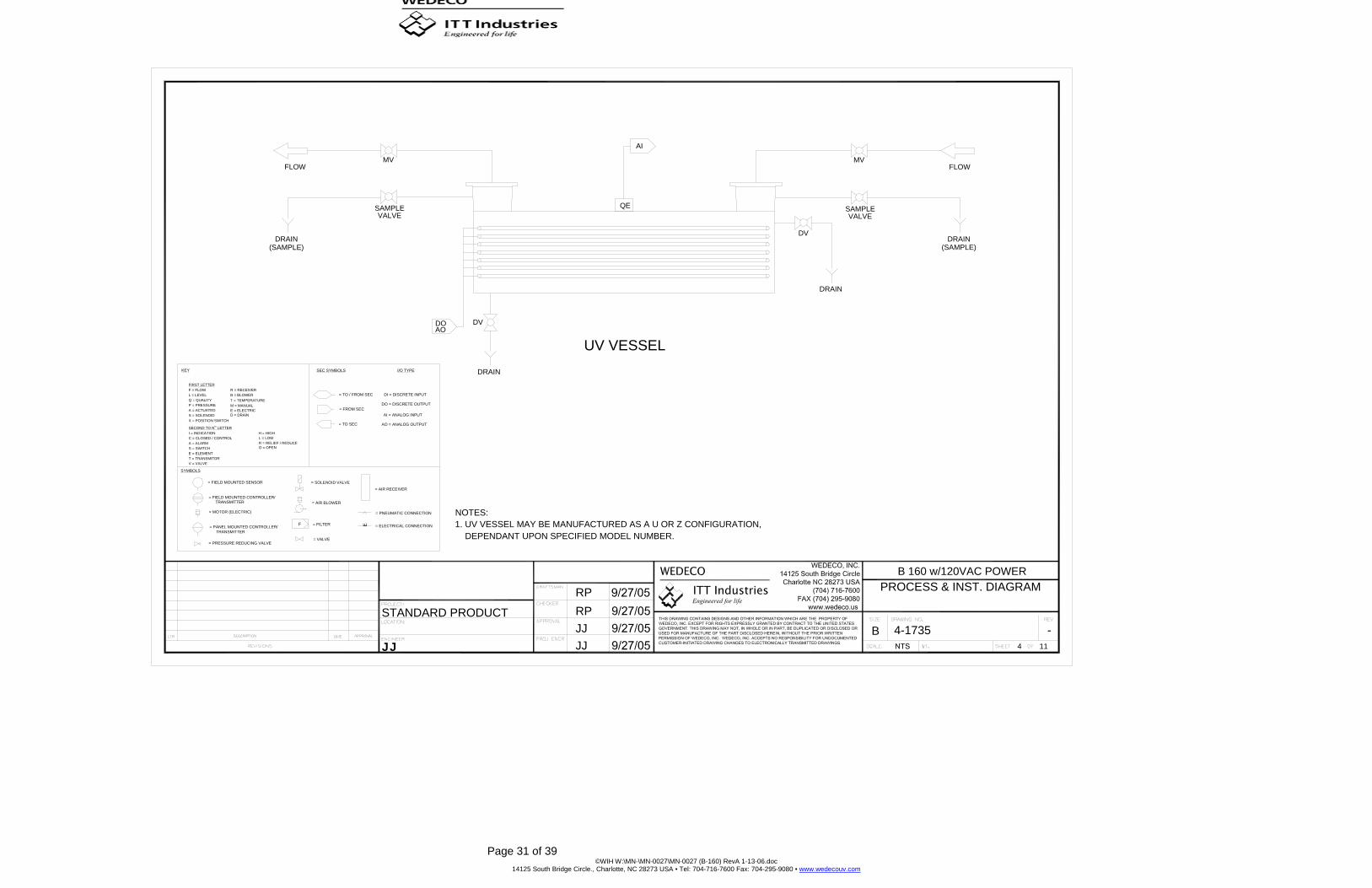
B 160 w/120VAC POWERPROCESS & INST. DIAGRAM
4-1735JJ
1. UV VESSEL MAY BE MANUFACTURED AS A U OR Z CONFIGURATION,DEPENDANT UPON SPECIFIED MODEL NUMBER.
QE
UV VESSELSEC SYMBOLS
= SOLENOID VALVE
= AIR BLOWER
KEY
SYMBOLS
E = ELEMENT
= FIELD MOUNTED SENSOR
= FIELD MOUNTED CONTROLLER/
= PANEL MOUNTED CONTROLLER/
= PRESSURE REDUCING VALVE
TRANSMITTER
TRANSMITTER
= MOTOR (ELECTRIC)
V = VALVET = TRANSMITOR
F = FILTER
= VALVE
H = HIGH
T = TEMPERATURE
L = LOW
O = OPENR = RELIEF / REDUCE
M = MANUALP = PRESSURE
X = POSITION SWITCH
SECOND TO N LETTER
C = CLOSED / CONTROLI = INDICATION
A = ALARMS = SWITCH
S = SOLENOIDA = ACTUATED
TH
D = DRAINE = ELECTRIC
L = LEVELQ = QUALITY
F = FLOWFIRST LETTER
B = BLOWERR = RECEIVER
NOTES:
DRAIN
= ELECTRICAL CONNECTION
= PNEUMATIC CONNECTION
= AIR RECEIVER
EI/O TYPE
DI = DISCRETE INPUT
DO = DISCRETE OUTPUT
AO = ANALOG OUTPUT
AI = ANALOG INPUT
= TO SEC
= FROM SEC
= TO / FROM SEC
FLOW
(SAMPLE)DRAIN
DVDOAO
VALVESAMPLE
MV
DRAIN
SAMPLE
DV
VALVE
AI
MVFLOW
DRAIN(SAMPLE)

Page 32 of 39 ©WIH W:\MN-\MN-0027\MN-0027 (B-160) RevA 1-13-06.doc
14125 South Bridge Circle., Charlotte, NC 28273 USA • Tel: 704-716-7600 Fax: 704-295-9080 • www.wedecouv.com
RPRP
STANDARD PRODUCT
JJJJ B
11
-5
B 160 w/120VAC POWERPOWER DISTRIBUTION
4-1735JJ
L1D
L2D
L1E
L2E
L1C
L2C
N1
L1B
N1
L1G
N1
N1

Page 33 of 39 ©WIH W:\MN-\MN-0027\MN-0027 (B-160) RevA 1-13-06.doc
14125 South Bridge Circle., Charlotte, NC 28273 USA • Tel: 704-716-7600 Fax: 704-295-9080 • www.wedecouv.com
RPRP
STANDARD PRODUCT
JJJJ B
11
-6
B 160 w/120VAC POWERLAMP CONTROLLER
4-1735JJ
SYSTEM FAILUREUV LAMPS ON
PRE ALERTANALOG
4-20mAOUTPUT
K-1
PREHEATING,IGNITING
TB3-5
K-2
13
14CR-3
SENSOR INPUT
WEDECO INC.
A1
ST S6
1 2
1
SEC_KOME
510
ANALOG OUT
11 12_ +
8 9
ST S5
1 2
ST S4
3 4
76 5
ST S3
7
SH. 6CR-5
12 8
11CR-6SH. 8
32 4
ST S1
I38794ST S7
ST S2
GND
A2
AWG 28-10F10 X AWG28(GRAY RIBBON)
SYSTEM RUNNING
CR-414
13
TB3-4
CABINET HIGH TEMPERATURE
2
14
13CR-5
SW2
50° C
WEDECOW35171
1
TB1-4
GRN BLK
/GR
YW
HT
BLU
/BR
NG
RN
5
UV SENSOR
GR
YTB
4-3
1B
RN
TB4-
2TB
4-4
523 4W
HT
BLU
BLK
TB4-
1342 1
UV
(GRAY RIBBON)(GRAY RIBBON)
12319 FC1
AWG 28-10F12319 FC2
(MULT COLOR RIBBON)10 X AWG28
RC
1
RC
2
RC
3
RC
4
RC
5

Page 34 of 39 ©WIH W:\MN-\MN-0027\MN-0027 (B-160) RevA 1-13-06.doc
14125 South Bridge Circle., Charlotte, NC 28273 USA • Tel: 704-716-7600 Fax: 704-295-9080 • www.wedecouv.com
RPRP
STANDARD PRODUCT
JJJJ B
11
-7
B 160 w/120VAC POWERLAMP MONITOR
4-1735JJ
8
LAMP MONITOR
JP1JP8
6B5-2
A3
3B7-2
B6-2
L1D
5
12
S2
I35169
4
S4
21 3 65 7
SEC_AUKO
S16
1
9 10
3S3
2
54
B4-2B3-2L1D
B2-2B1-2NC
4NCNC

Page 35 of 39 ©WIH W:\MN-\MN-0027\MN-0027 (B-160) RevA 1-13-06.doc
14125 South Bridge Circle., Charlotte, NC 28273 USA • Tel: 704-716-7600 Fax: 704-295-9080 • www.wedecouv.com
RPRP
STANDARD PRODUCT
JJJJ B
11
-8
B 160 w/120VAC POWERCUSTOMER CONTACTS
4-1735JJ
2 POS SWITCHLOCAL / REMOTE
SH.6
12
-
14
13
CR-6
518
+
12
CR-4
SH.8CR-6
SH.6
CR-3
SH.6
12CR-5
9CR-5
8
8
CR-6SH.8SH.610
1CR-3SH.6
9
5CR-3
TB5-
12
SH.8CR-6
6
51CR-4CR-4
9 9
5
9
SH.8
TB5-
11
TB5-
10
TB5-
9
TB5-
8
TB5-
7
TB5-
6
TB5-
5
TB5-
13
TB5-
14
TB5-
15
TB5-
16
TB5-
17
TB5-
18
TB5-
4
TB5-
3
TB5-
2
TB5-
1
RC
-6

Page 36 of 39 ©WIH W:\MN-\MN-0027\MN-0027 (B-160) RevA 1-13-06.doc
14125 South Bridge Circle., Charlotte, NC 28273 USA • Tel: 704-716-7600 Fax: 704-295-9080 • www.wedecouv.com
RPRP
STANDARD PRODUCT
JJJJ B
11
-9
B 160 w/120VAC POWERLAMP CIRCUITS
4-1735JJ
T46 6T26 T36T1
LAMP CONNECTIONS
TB3-5
LAMP # 2LAMP # 1
BKBNWH
GN
YE
TB2-
3
TB2-
2
TB2-
1
TB3-
5X100
BL
52
TB3-
9
5 2
GN
YE
BNWH
BK
TB3-
6B
L
2 5
TB3-
10
TB2-
6
TB2-
5
TB2-
4
5 2
TB7-1
G1
SH.6K2
C150uf
C230uf
1/2 WATT1 MR1
1/2 WATT1 MR2
TB6-1
3
78
3
78
31000K
N
PZS
2 6
3
78
3
87
TB6-2
1000KG2
N3
PZS
2 6
B1
4
2B2TB7-2
4
2
T7 T8666 6 T6T5
LAMP # 4LAMP # 3
BK GN
YEWH
BN
2
TB3-
10
TB2-
9
TB2-
8
TB2-
7
TB3-
6B
L
5 5
WH
BN
2
TB2-
10
TB3-
7
TB2-
11
BL
2 5
GN
YE
BK
TB3-
11
TB2-
12
5 2
TB7-3
3
78
78
PZS
2
1000K
N
TB6-3
G33
6
3 3
78
G4
TB6-4
1000K
N
PZS
2
3
6
B3
4
2
TB7-2B4
2
4
3
78
*
FOR THIS TERMINATION POINT.* FERRULE (PART# 15511)
INSURE USE OF 12mm
* * *

Page 37 of 39 ©WIH W:\MN-\MN-0027\MN-0027 (B-160) RevA 1-13-06.doc
14125 South Bridge Circle., Charlotte, NC 28273 USA • Tel: 704-716-7600 Fax: 704-295-9080 • www.wedecouv.com
RPRP
STANDARD PRODUCT
JJJJ B
11
-10
B 160 w/120VAC POWERLAMP CIRCUITS
4-1735JJ
3
87
56
TB2-
14BN
LAMP # 5
LAMP CONNECTIONS
TB3-6
BL WH
X100
TB3-
7
TB2-
13
GN
YE
BKTB
2-15
TB3-
11
30ufC4
1/2 WATT1 M
30ufC3
R3
PZSPZS
8
T92
65
7
3
TB6-51 M
1/2 WATT
R4
N
1000KG53
8
65
7
T102
3
T112
3
TB6-6
G6
N
1000K
2 6
4
B52
TB7-3
TB7-4
2
LAMP # 6
BKWHBL BN G
NY
E
TB2-
18
TB2-
16
TB3-
8
TB2-
17
TB3-
12
LAMP # 7
TB3-
12G
NY
E
BL BNWH
BK
TB3-
8
TB2-
20
TB2-
19
TB2-
21
PZS
3
2
8
65 2
7
3
T12 T13
TB6-7
G7
87
56
8
65
7
T142
3
N
1000K3
6
4
2B6 TB7-4B7
2 6
4
2
*
FOR THIS TERMINATION POINT.* FERRULE (PART# 15511)
INSURE USE OF 12mm
* *

Page 38 of 39 ©WIH W:\MN-\MN-0027\MN-0027 (B-160) RevA 1-13-06.doc
14125 South Bridge Circle., Charlotte, NC 28273 USA • Tel: 704-716-7600 Fax: 704-295-9080 • www.wedecouv.com
RPRP
STANDARD PRODUCT
JJJJ B
11
-11
B 160 w/120VAC POWERTERMINAL LAYOUT
4-1735JJ
L1 N L1B
GN
D
L1B
N1
26B
2-2
EN
D S
PAC
ER
1 2 43 5
B1-
6
B1-
5
B2-
6
B1-
2
B2-
5
97 8 1
B3-
2
B3-
6
B3-
5
EN
D S
PAC
ER
N1
53 4 6
N1
N1
N1
N1
1
GN
D
GN
D
GN
D
A1S
5-1
EN
D S
PAC
ER
GN
D
L1D
1
GR
EEN
/YE
LLO
W
GR
AY
GR
AY
GR
AY
GR
AY
2 3L1
D
L1D
B3N
INB
1NA
3
TB5-
99
A1S
5-11
332 4 1 2
EN
D S
PAC
ER
A1S
5-4
A1S
5-2
A1S
5-3
AU
X1
AU
X2
64 5 7 8
TB5-
6
A1S
5-12
TB5-
5
TB5-
7
TB5-
8
1110 12 1413 15
TB5-
11
TB5-
10
TB5-
12
TB5-
14
TB5-
13
A1S
5-9
1716 18
1 2
1NA
1NA
TB5-
17
A1S
5-8
A1S
5-10
EN
D S
PAC
ER
INB
INB
B1N
B2N
521 3 4 11 1312 14 161510 1211 13
B4-
6
B4-
2
B4-
5
B5-
6
1514 16 1817
B5-
2
B5-
5
B6-
6
B6-
2
B6-
5
2120
B7-
2
B7-
5
19B
7-6
N1
N1
87 109
GN
D
GN
D
GN
D
GN
D
41N
A
65
1NA
1NA
B4N
INB
B5N
B6N
INB
INB
71N
AB7
NIN
B
4 5
L1D
L1D
EN
D S
PAC
ER
EN
D S
PAC
ER
EN
D S
PAC
ER
EN
D S
PAC
ER
REM
OTE
OP
ERAT
ION
SW
ITC
H O
FF/O
N IN
PUT
AN
ALO
G O
UTP
UT,
4-2
0mA
REA
DY
FO
R F
LOW
OU
TPU
T
CAB
INET
HIG
H T
EM
PER
ATU
RE
CO
NTA
CTS
, OU
TPU
TS
SYS
TEM
FA
ILU
RE
CO
NTA
CTS
, OU
TPU
TS
SYS
TEM
RU
NN
ING
CO
NTA
CTS
, OU
TPU
T
NO
RM
AL/
RE
MO
TE C
ON
TAC
T
ALA
RM
CO
NTA
CTS
, CO
MM
ON
PR
E-A
LER
T C
ON
TAC
TS, O
UTP
UT
NO
RM
AL O
PER
ATIO
N C
ON
TAC
TS, O
UTP
UT
NC
NO
NC
NO
NO
C NC
NO
NC
NO
NO
NC
C
LAM
P #1
CO
NN
EC
TIO
NS
LAM
P #2
CO
NN
EC
TIO
NS
LAM
P #3
CO
NN
EC
TIO
NS
LAM
P #4
CO
NN
EC
TIO
NS
LAM
P #5
CO
NN
EC
TIO
NS
LAM
P #6
CO
NN
EC
TIO
NS
LAM
P #7
CO
NN
EC
TIO
NS
UV
SEN
SO
R C
ON
NEC
TIO
NS
Page 39 of 39 ©WIH W:\MN-\MN-0027\MN-0027 (B-160) RevA 1-13-06.doc
14125 South Bridge Circle., Charlotte, NC 28273 USA • Tel: 704-716-7600 Fax: 704-295-9080 • www.wedecouv.com
Manufactured by: WEDECO UV Technologies, Inc.
14125 South Bridge Circle South Point Business Park
Charlotte, NC 28273 Main: 704-716-7600 Fax: 704-716-7610 www.wedeco.us
Part # 15332, RevA, 1/13/06