installation instructions for part 99-3108 2 desmontaje del tablero – saturn ion 2003-2005 .....2
TRANSCRIPT

APPLICATIONS
METRA. The World’s best kits.™ metraonline.com1-800-221-0932 © COPYRIGHT 2004-2013 METRA ELECTRONICS CORPORATION
REV.
1/2
7/20
14
INST
99-3
108
CAUTION: Metra recommends disconnecting the negative battery terminal before beginning any installation. All accessories, switches, and especially air bag indicator lights must be plugged in before reconnecting the battery or cycling the ignition.
NOTE: Refer to the instructions included with the aftermarket radio.
INSTALLATION INSTRUCTIONS FOR PART 99-3108
• ISODINradioprovisionwithpocket• DoubleDINradioprovision
•A)Radiohousing•B)Radiohousingbrackets•C)Pocket•D)(4)#8x3/8”Phillipsscrews
KIT FEATURES
KIT COMPONENTS
WIRING & ANTENNA CONNECTIONS(soldseparately)
WiringHarness:•70-2002-Saturn2000-2005•70-2102-Saturn2002-2005
AntennaAdapter:•Notrequired
•Flatbladescrewdriver•Phillipsscrewdriver•Socketwrench
TOOLS REQUIRED
Saturn Ion 2003-2005, L Series 2000-2005,S Series 2000-2002, Vue 2002-2005
99-3108
A B C D
99-3108
2
Dash Disassembly
– SaturnIon2003-2005.........................................................................................2
– SaturnL2000-2005...........................................................................................2
– SaturnS2000-2002...........................................................................................3
– SaturnVue2002-2005........................................................................................3
Kit Assembly
– ISODINradioprovisionwithpocket.....................................................................4
– DoubleDINradioprovision..................................................................................4
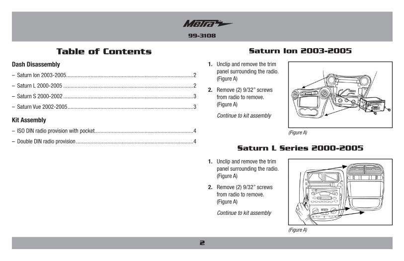
Table of Contents1. Unclipandremovethetrim
panelsurroundingtheradio.(FigureA)
2. Remove(2)9/32”screwsfromradiotoremove.(FigureA)
Continue to kit assembly
Saturn Ion 2003-2005
(Figure A)
1. Unclipandremovethetrimpanelsurroundingtheradio.(FigureA)
2. Remove(2)9/32”screwsfromradiotoremove.(FigureA)
Continue to kit assembly
Saturn L Series 2000-2005
(Figure A)

3
Dash Disassembly 99-3108
1. Remove(4)Phillipsfrompanelbelowsteeringcolumnandunclipandremove.(FigureA)
2. Remove(4)Phillipsscrewsfromthesteeringcolumntrimpanelandremove.(FigureB)
3. Remove(2)screwsfromtheendcap/ventontheleftsideofthesteeringcolumnthenunclipandremove.(FigureC)
4. Unclipandremovetheentiredashpanelsurroundingtheradio,instrumentclusterandA/Ccontrols.(FigureD)
5. Remove(2)9/32”screwssecuringtheheadunittoremove.(FigureD)
Continue to kit assembly
Saturn S Series 2000-2002
(Figure D)
1. Unsnapandremoveshiftertrimpanel.(FigureA)
2. Remove(4)9/32”screwsfromthedashpocketandremove.(FigureA)
3. UnsnapandremovepanelsurroundingradioandA/Ccontrols.(FigureA)
4. Remove(2)9/32”screwsfromradiotoremove.(FigureA)
Continue to kit assembly
Saturn Vue 2002-2005
(Figure A) (Figure B)
(Figure C)
(Figure A)
Turn signal indicator
Shiftindicator
Dashside view
4
Kit Assembly 99-3108
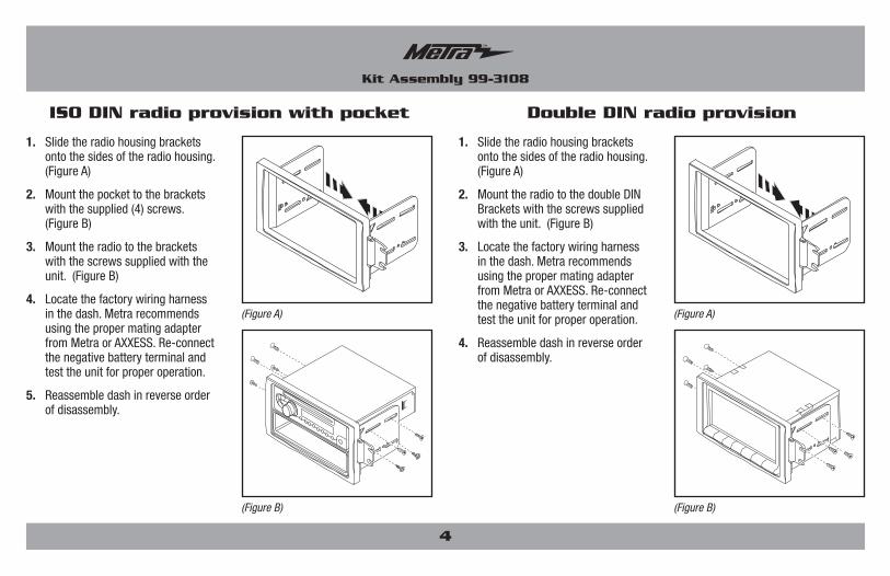
1. Slidetheradiohousingbracketsontothesidesoftheradiohousing.(FigureA)
2. Mountthepockettothebracketswiththesupplied(4)screws.(FigureB)
3. Mounttheradiotothebracketswiththescrewssuppliedwiththeunit.(FigureB)
4. Locatethefactorywiringharnessinthedash.MetrarecommendsusingthepropermatingadapterfromMetraorAXXESS.Re-connectthenegativebatteryterminalandtesttheunitforproperoperation.
5. Reassembledashinreverseorderofdisassembly.
ISO DIN radio provision with pocket
1. Slidetheradiohousingbracketsontothesidesoftheradiohousing.(FigureA)
2. MounttheradiotothedoubleDINBracketswiththescrewssuppliedwiththeunit.(FigureB)
3. Locatethefactorywiringharnessinthedash.MetrarecommendsusingthepropermatingadapterfromMetraorAXXESS.Re-connectthenegativebatteryterminalandtesttheunitforproperoperation.
4. Reassembledashinreverseorderofdisassembly.
Double DIN radio provision
(Figure B)
(Figure A)
(Figure B)
(Figure A)

Notes

Notes

Notes

METRA. The World’s best kits.™ metraonline.com1-800-221-0932 © COPYRIGHT 2004-2013 METRA ELECTRONICS CORPORATION
REV.
1/2
7/20
14
INST
99-3
108
KNOWLEDGE IS POWEREnhance your installation and fabrication skills by enrolling in the most recognized and respected mobile electronics school in our industry.Log onto www.installerinstitute.com or call 800-354-6782 for more information and take steps toward a better tomorrow.
Metra recommends MECP certified technicians
INSTALLATION INSTRUCTIONS FOR PART 99-3108

APLICACIONES
METRA. The World’s best kits.™ metraonline.com1-800-221-0932 © COPYRIGHT 2004-2013 METRA ELECTRONICS CORPORATION
REV.
1/2
7/20
14
INST
99-3
108
PRECAUCIÓN: Metra recomienda desconectar el terminal negativo de la batería antes de comenzar cualquier instalación. Todos los accesorios, interruptores y, especialmente, las luces indicadoras de airbag deben estar enchufados antes de volver a conectar la batería o comenzar el ciclo de ignición.
NOTA: Remítase a las instrucciones incluidas con el radio de postventa.
INSTRUCCIONES DE INSTALACIÓN PARA LA PIEZA 99-3108
• ProvisiónderadioISODINconbolsillo• ProvisiónderadiodobleDIN
•A)Alojamientodelradio•B)Soportesdecarcasadelradio•C)Bolsillo•D)(4)TornillosPhillips#8x3/8”
CArACtEríStICAS dEL kIt
COmPONENtES dEL kIt
•Destornilladordehojaplana•DestornilladorPhillips•Llavedetubo
HErrAmIENtAS rEquErIdAS
Saturn Ion 2003-2005, L Series 2000-2005,S Series 2000-2002, Vue 2002-2005
99-3108
CABLEAdO Y CONEXIONES dE ANtENAArnésdecableado:
•70-2002-Saturn2000-2005•70-2102-Saturn2002-2005
Adaptadordeantena:•Noserequiere
(sevendenporseparado)
A B C D
99-3108
2
Desmontaje del tablero
– SaturnIon2003-2005.........................................................................................2
– SaturnL2000-2005...........................................................................................2
– SaturnS2000-2002...........................................................................................3
– SaturnVue2002-2005........................................................................................3
Ensamble del kit
– ProvisiónderadioISODINconbolsillo................................................................4
– ProvisiónderadiodobleDIN................................................................................4
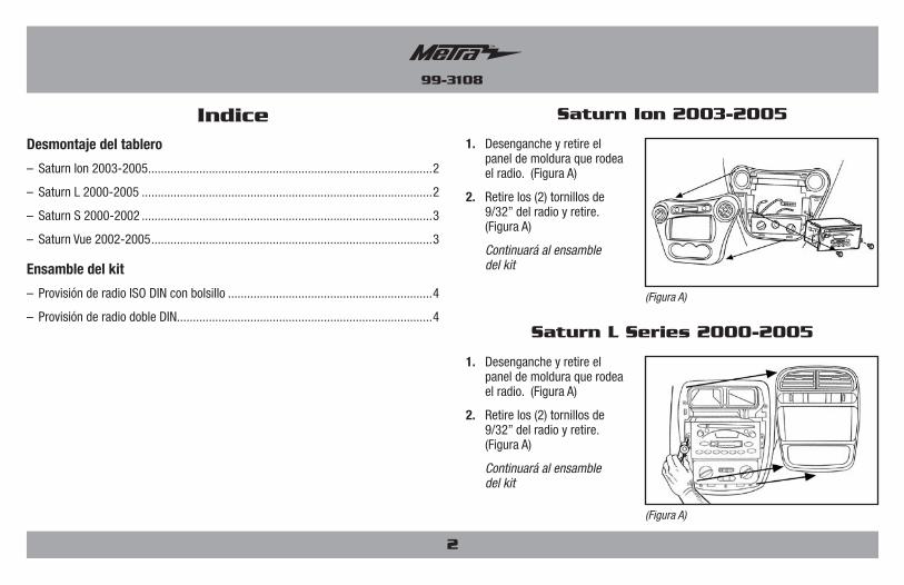
Indice1. Desengancheyretireel
paneldemolduraquerodeaelradio.(FiguraA)
2. Retirelos(2)tornillosde9/32”delradioyretire.(FiguraA)
Continuará al ensamble del kit
Saturn Ion 2003-2005
(Figura A)
1. Desengancheyretireelpaneldemolduraquerodeaelradio.(FiguraA)
2. Retirelos(2)tornillosde9/32”delradioyretire.(FiguraA)
Continuará al ensamble del kit
Saturn L Series 2000-2005
(Figura A)
3
Desmontaje del tablero 99-3108
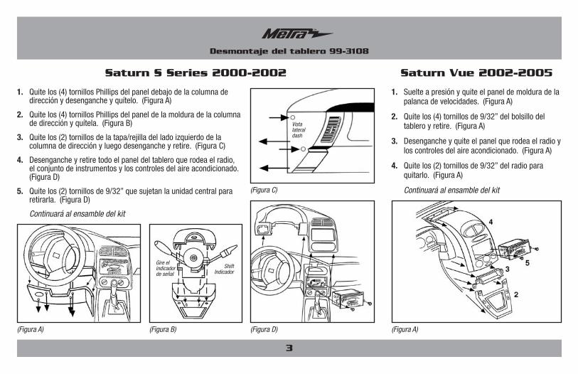
1. Quitelos(4)tornillosPhillipsdelpaneldebajodelacolumnadedirecciónydesengancheyquítelo.(FiguraA)
2. Quitelos(4)tornillosPhillipsdelpaneldelamolduradelacolumnadedirecciónyquítela.(FiguraB)
3. Quitelos(2)tornillosdelatapa/rejilladelladoizquierdodelacolumnadedirecciónyluegodesengancheyretire.(FiguraC)
4. Desengancheyretiretodoelpaneldeltableroquerodeaelradio,elconjuntodeinstrumentosyloscontrolesdelaireacondicionado.(FiguraD)
5. Quitelos(2)tornillosde9/32”quesujetanlaunidadcentralpararetirarla.(FiguraD)
Continuará al ensamble del kit
Saturn S Series 2000-2002
(Figura D)
1. Suelteapresiónyquiteelpaneldemolduradelapalancadevelocidades.(FiguraA)
2. Quitelos(4)tornillosde9/32”delbolsillodeltableroyretire.(FiguraA)
3. Desengancheyquiteelpanelquerodeaelradioyloscontrolesdelaireacondicionado.(FiguraA)
4. Quitelos(2)tornillosde9/32”delradioparaquitarlo.(FiguraA)
Continuará al ensamble del kit
Saturn Vue 2002-2005
(Figura A) (Figura B)
(Figura C)
(Figura A)
Gire el indicador de señal
Shift Indicador
Vista lateral dash

4
Ensamble del kit 99-3108
1. Deslicelossoportesdecarcasadelradiosobrelosladosdelacarcasadelradio.(FiguraA)
2. Monteelbolsilloenlossoportesconlos(4)tornillossuministrados.(FiguraB)
3. Monteelradioenlossoportesconlostornillossuministradosconlaunidad.(FiguraB)
4. Ubiqueelarnésdelcableadodefábricaeneltablero.MetrarecomiendausareladaptadordeacoplamientoadecuadodeMetraoAXXESS.Vuelvaaconectarelterminalnegativodelabateríaypruebelaunidadparaverificarquefuncionecorrectamente.
5. Vuelvaamontareltableroenformainversaaldesmontaje.
Provisión de radio ISO DIN con bolsillo
1. Deslicelossoportesdecarcasadelradiosobrelosladosdelacarcasadelradio.(FiguraA)
2. MonteelradioenlossoportesDDINconlostornillosquevienenconlaunidad.(FiguraB)
3. Ubiqueelarnésdelcableadodefábricaeneltablero.MetrarecomiendausareladaptadordeacoplamientoadecuadodeMetraoAXXESS.Vuelvaaconectarelterminalnegativodelabateríaypruebelaunidadparaverificarquefuncionecorrectamente.
4. Vuelvaamontareltableroenformainversaaldesmontaje.
Provisión de radio doble DIN
(Figura B)
(Figura A)
(Figura B)
(Figura A)

Notas
Notas

Notas
METRA. The World’s best kits.™ metraonline.com1-800-221-0932 © COPYRIGHT 2004-2013 METRA ELECTRONICS CORPORATION
REV.
1/2
7/20
14
INST
99-3
108
KNOWLEDGE IS POWEREnhance your installation and fabrication skills by enrolling in the most recognized and respected mobile electronics school in our industry.Log onto www.installerinstitute.com or call 800-354-6782 for more information and take steps toward a better tomorrow.
Metra recomienda técnicos con certificación del Programa de Certificación en Electrónica Móvil (Mobile Electronics Certification Program, MECP).
EL CONOCIMIENTO ES PODERMejoresushabilidadesdeinstalaciónyfabricacióninscribiéndoseenlaescueladedispositivoselectrónicosmóvilesmásreconocidayrespetadadenuestraindustria.Regístreseenwww.installerinstitute.comollameal800-354-6782paraobtenermásinformaciónyavancehaciaunfuturomejor.
INSTRUCCIONES DE INSTALACIÓN PARA LA PIEZA 99-3108