installation instructions lumiwall pulley system · 7p-lumiwallpou installing the hoisting system...
TRANSCRIPT

VERSION 1.0- 18/03/13 7P-LUMIWALLPOU
Installation Instructions
LUMIWALL
Pulley System
Ventilation Secco division of Secco International inc. 4040 blvd. Casavant West St-Hyacinthe, Qc J2S 8E3 T: 450-771-0777 F: 450-771-5779 [email protected]

7P-LUMIWALLPOU
NOTICE TO PROJECT CONTRACTOR:
Please Refer Yourself To The Secco Dealer For Any Questions On Installation Plans And
Specifications.
7P-LUMIWALLPOU
This document contains all information related to: The drive mechanisms:
1. Pulley
BEFORE YOU INSTALL YOUR NEW SECCO VENTILATION SYSTEM, WE RECOMMEND THAT YOU: 1. DOUBLE-CHECK THAT THE HARDWARE DELIVERED CORRESPONDS TO THAT LISTED ON YOUR DELIVERY SLIP. 2. MEASURE THE VENTILATION OPENING AS WELL AS THE PANELS DELIVERED. THE PANEL SHOULD BE 4 INCHES (10 CM) LONGER THAN THE HEIGHT AND WIDTH OF THE OPENING. THANK YOU FOR TRUSTING US WITH YOUR VENTILATION NEEDS. WE WISH YOU A SMOOTH INSTALLATION!
7P-LUMIWALLPOU
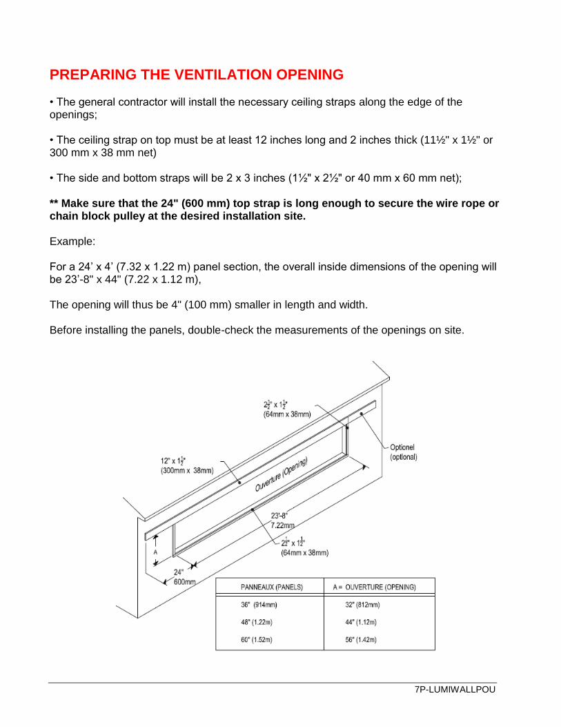
PREPARING THE VENTILATION OPENING • The general contractor will install the necessary ceiling straps along the edge of the openings; • The ceiling strap on top must be at least 12 inches long and 2 inches thick (11½" x 1½" or 300 mm x 38 mm net) • The side and bottom straps will be 2 x 3 inches (1½" x 2½" or 40 mm x 60 mm net); ** Make sure that the 24" (600 mm) top strap is long enough to secure the wire rope or chain block pulley at the desired installation site. Example: For a 24’ x 4’ (7.32 x 1.22 m) panel section, the overall inside dimensions of the opening will be 23’-8" x 44" (7.22 x 1.12 m), The opening will thus be 4" (100 mm) smaller in length and width. Before installing the panels, double-check the measurements of the openings on site.

7P-LUMIWALLPOU
INSTALLING THE BIRD BARRIER (OPTIONAL) Installing a bird barrier is optional and at the client’s discretion; It is important to properly stretch out the wire fence before securing it to the wall (see diagram below); Secure the wire fence to the structure with 1¼" (31 mm) nails or clips at 6" (150 mm) intervals.

7P-LUMIWALLPOU
INSTALLING THE HOISTING SYSTEM (PULLEY SYSTEM)
Outside wire rope pulley (PC-105)
Determine the installation site for the outside wire rope pulley (PC-105). It should be on either the right or left side of the ventilation wall.
Then, drill a hole for the master cable.
A DOUBLE PULLEY KIT - 5'' (127mm) (PC-105)
B 8- ZINC LAG SCREW - 1/4 X 1-1/2'' (6mm x 38mm)
INSIDE WIRE ROPE PULLEY (PA-105) / (PC-105)
Determine the installation site for the inside wire rope pulley.
For a manual ventilation system, the pulley (PA-105) must be installed as seen on the diagram.
For an automatic ventilation system, a pulley (PC-105) is only necessary if the cable turns at a 180º angle, i.e. the actuator is above the ventilation opening. No pulley is needed when the actuator is perpendicular to the opening (90º).

7P-LUMIWALLPOU
MANUAL SYSTEM
A PULLEY BRACKET KIT - 5'' (127mm) (PA-105)
B 8 - ZINC LAG SCREW - 1/4 X 1-1/2'' (6mm x 38mm)
AUTOMATIC SYSTEM (IF THE ACTUATOR IS ABOVE THE OPENING)
A DOUBLE PULLEY KIT - 5'' (127mm)
B 8- ZINC LAG SCREW - 1/4 X 1-1/2'' (6mm x 38mm)

7P-LUMIWALLPOU
A. MANUAL WINCH
To install the manual winch, align it with the previously installed pulley (PA-105). Follow the instructions below.
A 1- WINCH - 2500 LBS (1135KG)
B 1- GALV. WINCH BRACKET
C 1- WINCH BRACKET REINFORCEMENT PLATE
D 3- HEX BOLT - 3/8"X 1 1/4" (9.52mm x 31.75mm)
E 3- NYLON LOCK NUT SS304 3/8-16 NC (9.52mm)
F 6- ZINC LAG SCREW - 5/16 X 3 (8mm X 76mm)
G 8- ZINC LAG SCREW - 1/4 X 1-1/2'' (6mm x 38mm)
H 8- ZINC LAG SCREW ZINC 1/4 X 1-1/2'' (6mm x 38mm)
7P-LUMIWALLPOU
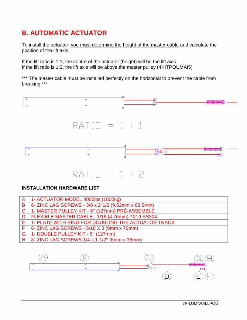
B. AUTOMATIC ACTUATOR
To install the actuator, you must determine the height of the master cable and calculate the position of the lift axis. If the lift ratio is 1:1, the centre of the actuator (height) will be the lift axis. If the lift ratio is 1:2, the lift axis will be above the master pulley (4KITPOUMAI5) *** The master cable must be installed perfectly on the horizontal to prevent the cable from breaking.***
INSTALLATION HARDWARE LIST
A 1- ACTUATOR MODEL 4000lbs (1800kg)
B 6- ZINC LAG SCREWS - 3/8 x 2''1/2 (9.52mm x 63.5mm)
C 1- MASTER PULLEY KIT - 5'' (127mm) PRÉ-ASSEMBLÉ
D FLEXIBLE MASTER CABLE - 3/16 (4.76mm) 7X19 SS304
E 1- PLATE WITH RING FOR DOUBLING THE ACTUATOR TRACK
F 6- ZINC LAG SCREWS - 5/16 X 3 (8mm x 76mm)
G 1- DOUBLE PULLEY KIT - 5'' (127mm)
H 8- ZINC LAG SCREWS 1/4 x 1-1/2'' (6mm x 38mm)
7P-LUMIWALLPOU
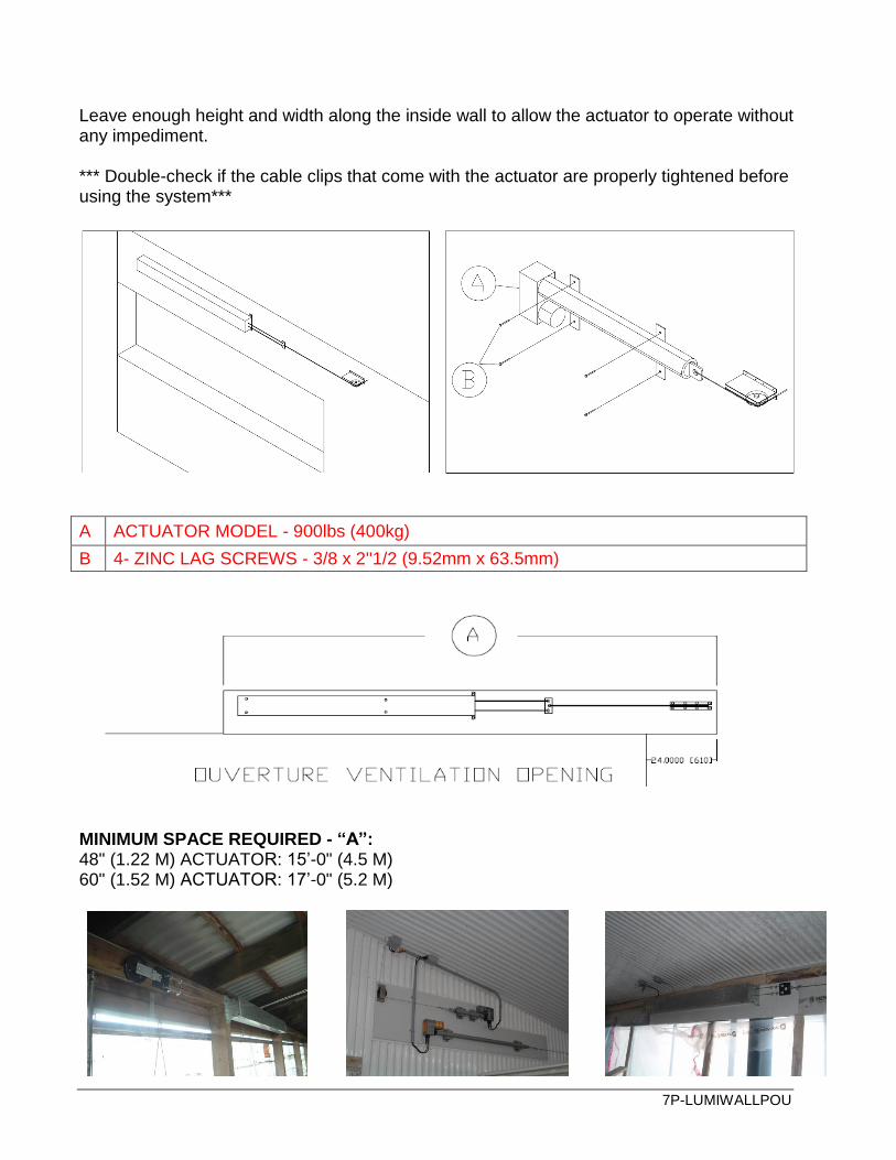
Leave enough height and width along the inside wall to allow the actuator to operate without any impediment. *** Double-check if the cable clips that come with the actuator are properly tightened before using the system***
A ACTUATOR MODEL - 900lbs (400kg)
B 4- ZINC LAG SCREWS - 3/8 x 2''1/2 (9.52mm x 63.5mm)
MINIMUM SPACE REQUIRED - “A”: 48" (1.22 M) ACTUATOR: 15’-0" (4.5 M) 60" (1.52 M) ACTUATOR: 17’-0" (5.2 M)
7P-LUMIWALLPOU
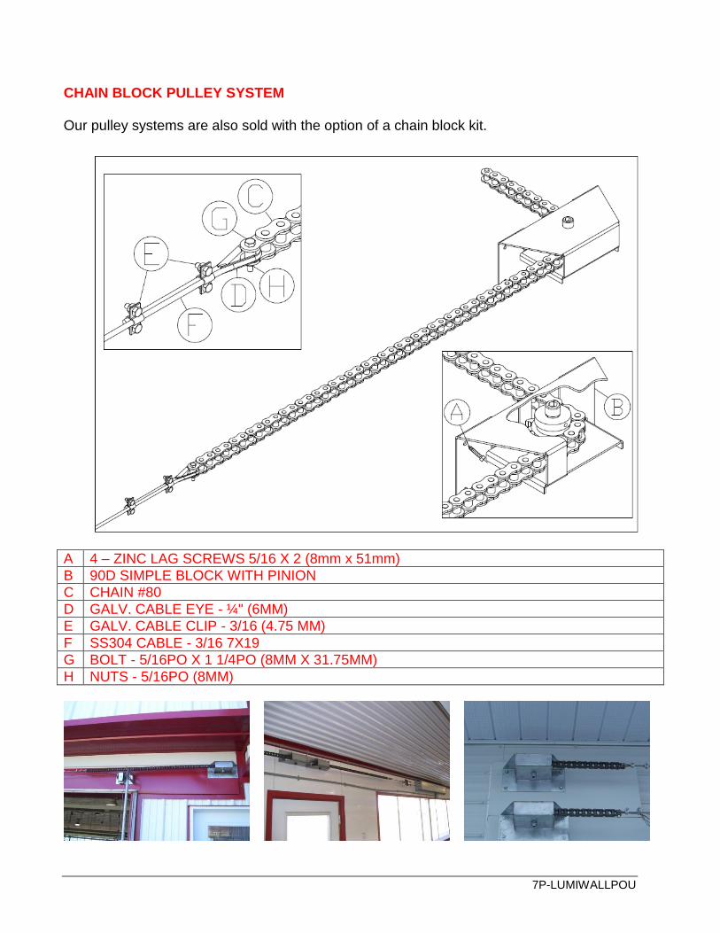
CHAIN BLOCK PULLEY SYSTEM Our pulley systems are also sold with the option of a chain block kit.
A 4 – ZINC LAG SCREWS 5/16 X 2 (8mm x 51mm)
B 90D SIMPLE BLOCK WITH PINION
C CHAIN #80
D GALV. CABLE EYE - ¼" (6MM)
E GALV. CABLE CLIP - 3/16 (4.75 MM)
F SS304 CABLE - 3/16 7X19
G BOLT - 5/16PO X 1 1/4PO (8MM X 31.75MM)
H NUTS - 5/16PO (8MM)
7P-LUMIWALLPOU
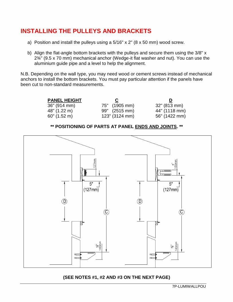
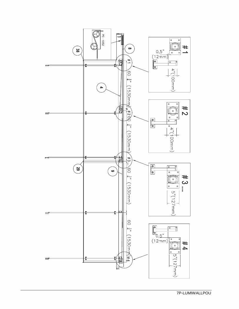
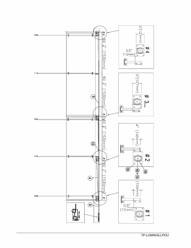
INSTALLING THE PULLEYS AND BRACKETS
a) Position and install the pulleys using a 5/16" x 2" (8 x 50 mm) wood screw. b) Align the flat-angle bottom brackets with the pulleys and secure them using the 3/8" x
2¾" (9.5 x 70 mm) mechanical anchor (Wedge-it flat washer and nut). You can use the aluminium guide pipe and a level to help the alignment.
N.B. Depending on the wall type, you may need wood or cement screws instead of mechanical anchors to install the bottom brackets. You must pay particular attention if the panels have been cut to non-standard measurements.
PANEL HEIGHT C D 36" (914 mm) 75" (1905 mm) 32" (813 mm)
48" (1.22 m) 99" (2515 mm) 44" (1118 mm) 60" (1.52 m) 123" (3124 mm) 56" (1422 mm)
** POSITIONING OF PARTS AT PANEL ENDS AND JOINTS. **
(SEE NOTES #1, #2 AND #3 ON THE NEXT PAGE)
7P-LUMIWALLPOU
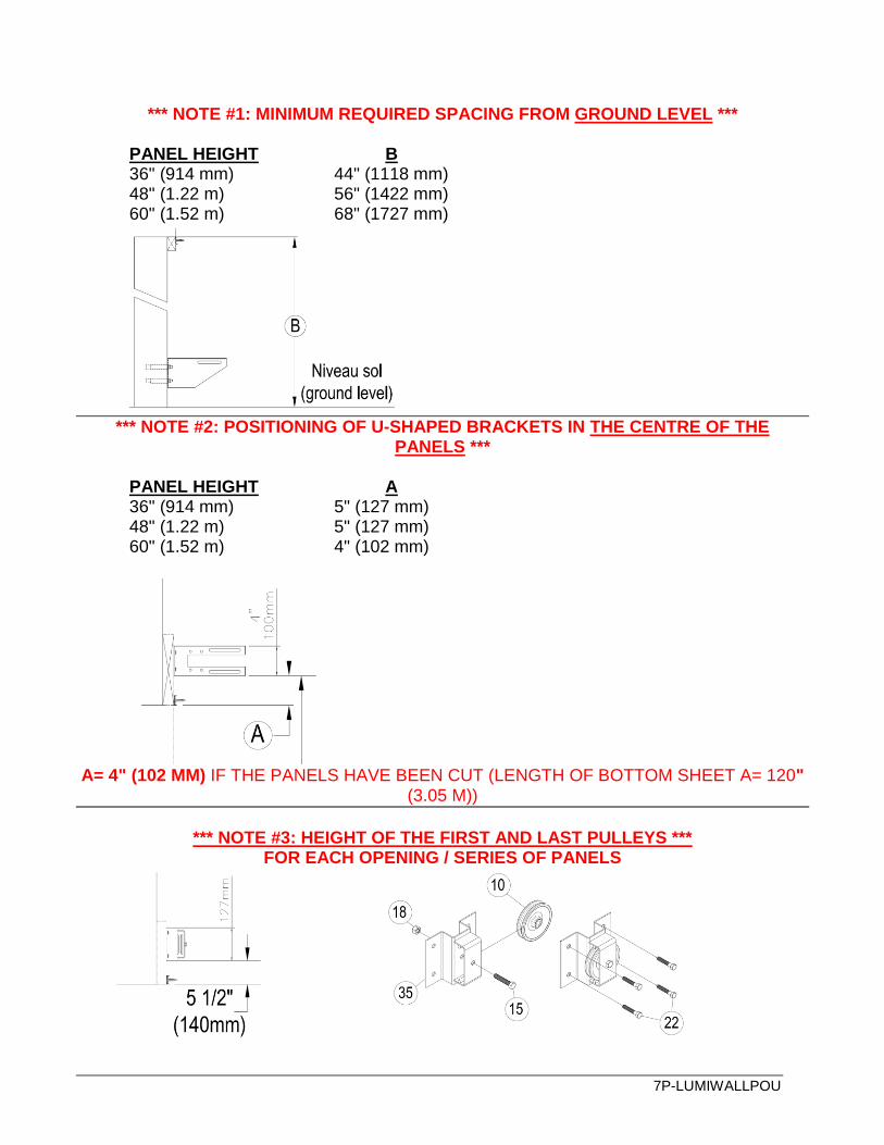
*** NOTE #1: MINIMUM REQUIRED SPACING FROM GROUND LEVEL ***
PANEL HEIGHT B 36" (914 mm) 44" (1118 mm)
48" (1.22 m) 56" (1422 mm) 60" (1.52 m) 68" (1727 mm)
*** NOTE #2: POSITIONING OF U-SHAPED BRACKETS IN THE CENTRE OF THE
PANELS ***
PANEL HEIGHT A 36" (914 mm) 5" (127 mm)
48" (1.22 m) 5" (127 mm) 60" (1.52 m) 4" (102 mm)
A= 4" (102 MM) IF THE PANELS HAVE BEEN CUT (LENGTH OF BOTTOM SHEET A= 120"
(3.05 M))
*** NOTE #3: HEIGHT OF THE FIRST AND LAST PULLEYS ***
FOR EACH OPENING / SERIES OF PANELS
7P-LUMIWALLPOU
7P-LUMIWALLPOU
7P-LUMIWALLPOU

7P-LUMIWALLPOU
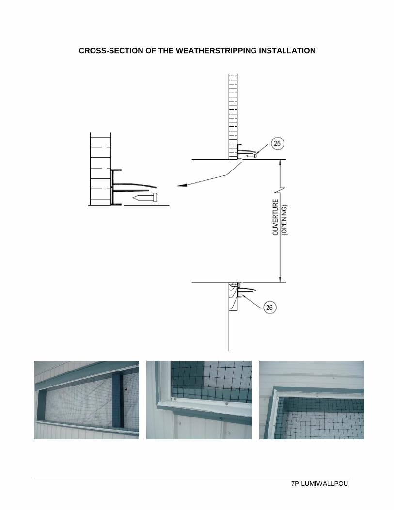
INSTALLING THE WEATHERSTRIPPING
Note that the elongated lip will be installed near the top for the longitudinal weather-stripping and towards the outside of the opening for the vertical weather stripping. (See details below)
Install the longitudinal and vertical weather-stripping on the opening’s wooden frames using the #8-18 X 1'' (#8 x 25 mm) PAN S/S TEK SCREW
Cut the weather-stripping on an angle as shown below;
NOTE: The inside measurements between the vertical weather-stripping should be similar to those in Step 1. Ex: 23' - 8" (7.22 m).
7P-LUMIWALLPOU
CROSS-SECTION OF THE WEATHERSTRIPPING INSTALLATION

7P-LUMIWALLPOU
PREPARING THE PANELS FOR ASSEMBLY a) Remove the protective film from the inside face of each panel. **Keep the protective film on the UV-exposed face up until the end. b) Apply a self-adhesive protective band on each end of the panel at a height of approx. 38'' (965 mm) for a 36'' panel, approx. 50" (1270 mm) for a 48'' panel and approx. 62'' (1584 mm) for a 60'' panel. Once you have applied them to the panels, trim the edges.
7P-LUMIWALLPOU
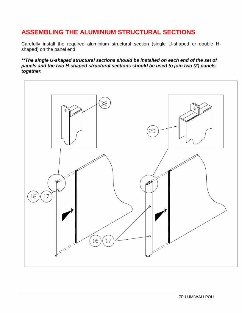
ASSEMBLING THE ALUMINIUM STRUCTURAL SECTIONS Carefully install the required aluminium structural section (single U-shaped or double H-shaped) on the panel end. **The single U-shaped structural sections should be installed on each end of the set of panels and the two H-shaped structural sections should be used to join two (2) panels together.
7P-LUMIWALLPOU
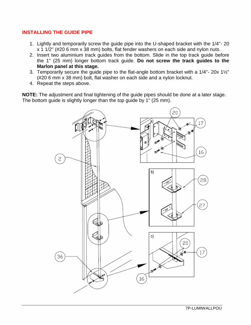
INSTALLING THE GUIDE PIPE
1. Lightly and temporarily screw the guide pipe into the U-shaped bracket with the 1/4"- 20 x 1 1/2" (#20 6 mm x 38 mm) bolts, flat fender washers on each side and nylon nuts.
2. Insert two aluminium track guides from the bottom. Slide in the top track guide before the 1" (25 mm) longer bottom track guide. Do not screw the track guides to the Marlon panel at this stage.
3. Temporarily secure the guide pipe to the flat-angle bottom bracket with a 1/4"- 20x 1½" (#20 6 mm x 38 mm) bolt, flat washer on each side and a nylon locknut.
4. Repeat the steps above.
NOTE: The adjustment and final tightening of the guide pipes should be done at a later stage. The bottom guide is slightly longer than the top guide by 1" (25 mm).

7P-LUMIWALLPOU
ASSEMBLING THE PANELS Position the panels so that the sides with the UV protective film face outside.
Carefully place and adjust the panels on the flat-angle bottom brackets. This is just temporary.
NOTE: Only the UV-exposed face is treated. It is important that this side face the exterior, or else the warranty will be cancelled.
7P-LUMIWALLPOU
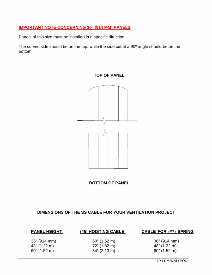
IMPORTANT NOTE CONCERNING 36" (914 MM) PANELS Panels of this size must be installed in a specific direction.
The curved side should be on the top, while the side cut at a 90º angle should be on the bottom.
TOP OF PANEL
BOTTOM OF PANEL
DIMENSIONS OF THE SS CABLE FOR YOUR VENTILATION PROJECT
PANEL HEIGHT (#5) HOISTING CABLE CABLE FOR (#7) SPRING
36" (914 mm) 60" (1.52 m) 36" (914 mm)
48" (1.22 m) 72" (1.82 m) 48" (1.22 m) 60" (1.52 m) 84" (2.13 m) 60" (1.52 m)
7P-LUMIWALLPOU
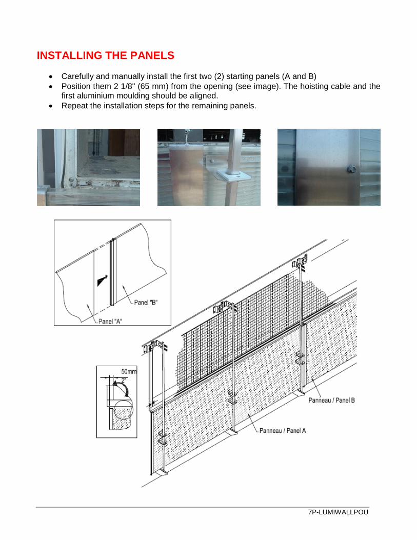
INSTALLING THE PANELS
Carefully and manually install the first two (2) starting panels (A and B)
Position them 2 1/8" (65 mm) from the opening (see image). The hoisting cable and the first aluminium moulding should be aligned.
Repeat the installation steps for the remaining panels.
7P-LUMIWALLPOU
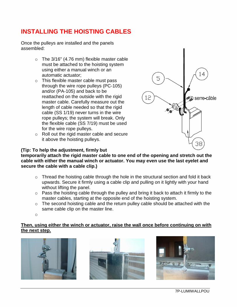
INSTALLING THE HOISTING CABLES Once the pulleys are installed and the panels assembled:
o The 3/16" (4.76 mm) flexible master cable must be attached to the hoisting system using either a manual winch or an automatic actuator;
o This flexible master cable must pass through the wire rope pulleys (PC-105) and/or (PA-105) and back to be reattached on the outside with the rigid master cable. Carefully measure out the length of cable needed so that the rigid cable (SS 1/19) never turns in the wire rope pulleys; the system will break. Only the flexible cable (SS 7/19) must be used for the wire rope pulleys.
o Roll out the rigid master cable and secure it above the hoisting pulleys.
(Tip: To help the adjustment, firmly but temporarily attach the rigid master cable to one end of the opening and stretch out the cable with either the manual winch or actuator. You may even use the last eyelet and secure the cable with a cable clip.)
o Thread the hoisting cable through the hole in the structural section and fold it back upwards. Secure it firmly using a cable clip and pulling on it lightly with your hand without lifting the panel.
o Pass the hoisting cable through the pulley and bring it back to attach it firmly to the master cables, starting at the opposite end of the hoisting system.
o The second hoisting cable and the return pulley cable should be attached with the same cable clip on the master line.
o
Then, using either the winch or actuator, raise the wall once before continuing on with the next step.
7P-LUMIWALLPOU
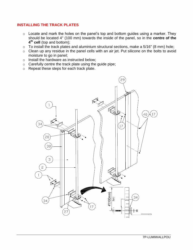
INSTALLING THE TRACK PLATES
o Locate and mark the holes on the panel’s top and bottom guides using a marker. They should be located 4" (100 mm) towards the inside of the panel, so in the centre of the 4th cell (top and bottom);
o To install the track plates and aluminium structural sections, make a 5/16" (8 mm) hole; o Clean up any residue in the panel cells with an air jet. Put silicone on the bolts to avoid
moisture to go in panel; o Install the hardware as instructed below; o Carefully centre the track plate using the guide pipe; o Repeat these steps for each track plate.

7P-LUMIWALLPOU
IMPORTANT NOTE CONCERNING THE PREVIOUS STEP
1. When drilling a hole in the Lumiwall sheet, make sure to turn the drill rapidly without applying force to the inside cells. The first wall is rigid, but the inside cells are fragile.
2. Be sure to always have a well-sharpened drill bit on hand. 3. Make sure that the drill is parallel to the Lumiwall sheet when proceeding to drill holes. 4. Always centre the guide pipe with the aluminium plate. 5. Lightly tighten the two aluminium track plates (top and bottom). 6. Inspect the inside cells one last time before completing the installation.
Remember that the primary goal of these precautions is to avoid breaking the material during the installation process. If these precautions are not heeded, cracks could appear on the inside walls. In this case, the warranty will not cover the material as the damage occurred during the installation. Always handle the sheets with care and follow each installation step with attention to detail. ADJUSTING AND INSTALLING THE SPRINGS
o Using a winch or the actuator, slowly raise the ventilation panels to their full height (‘closed’ mode). Make adjustments as needed until the weather-stripping is compressed by app. 1" (25 mm). (See cross-section below)
o Carefully position the guide pipes at an inclination of app. 2" (50 mm) and tighten them. o Double-check the bolts on all the panels and accessories.

7P-LUMIWALLPOU
7P-LUMIWALLPOU
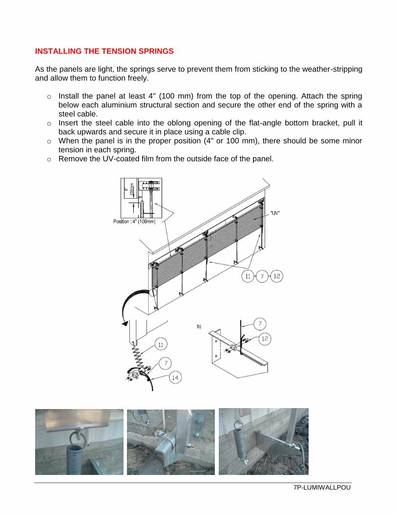
INSTALLING THE TENSION SPRINGS As the panels are light, the springs serve to prevent them from sticking to the weather-stripping and allow them to function freely.
o Install the panel at least 4" (100 mm) from the top of the opening. Attach the spring below each aluminium structural section and secure the other end of the spring with a steel cable.
o Insert the steel cable into the oblong opening of the flat-angle bottom bracket, pull it back upwards and secure it in place using a cable clip.
o When the panel is in the proper position (4" or 100 mm), there should be some minor tension in each spring.
o Remove the UV-coated film from the outside face of the panel.
7P-LUMIWALLPOU

7P-LUMIWALLPOU
LIST OF PARTS / LUMIWALL PANEL
No Description Unit code
1 TRACK PLATE WITH SQUARE BOLT 1ASSPLAQGLISS
2 PANEL GUIDE PIPE 1TUYGUID36/48/60
3 MARLON SHEET - 25 MM THICK 10' X 49-1/4'' 2MARLON25MM10
4 DOUBLING SS CABLE - 1/8 20’ (6M) 4CABSS3/16
5 SS 1/8 CABLE - HOISTING CABLE 4CABSS1/8
6 SS304 PI.LI. CABLE - 1/8 7X19 (ROLL 250') 4CABSS1/8719
7 SS CABLE – SPRING CABLE - 1/8 48'' 4CABSS1/8MAR
8 FLEXIBLE SS304 CABLE – 3/16 7X19 (4.76MM X 7-19) 4CABSS3/16
9 RIGID SS304 CABLE - 3/16 1X19 (4.76MM X 1-19) 4CABSS3/16119
10 PULLEY ON WHEELS - 3 1/2'' (89MM) 4PO3.5NBE
11 MARLON PANEL SPRING 4RESSMAR
12 GALV CABLE CLIP - 1/8 (3.18MM) 4SERCA1/8G
13 GALV CABLE CLIP - 3/16 (4.75MM) 4SERCA3/16G
14 ALUMINIUM CABLE BRAKE 8ALUMST1/8
15 SS304 HEX BOLT - 3/8 X 2 (50MM) 8BOHEXSS382
16 SS HEX BOLT - 1 1/2 X 1/4-20 (38MM X 6MM) 8BOUHEX14112
17 SS304 NYLON LOCK NUT 1/4-20 NC (6MM) 8ECRNYL1/4
18 NYLON NUT - 3/8" (9.52MM) 8ECRNYL3/8
19 WEDGE ANCHOR - 3/8 X 2 3/4'' (9.52MM X 70MM) 8ENCWEDG23/4
20 FENDER WASHER - 1/4 X 1-1/4 (6MM X 32MM) 8FEWAS1/4
21 MARLON PANEL TAPE 8TAPEMARLON
22 ZINC LAG SCREW - 5/16 X 2 (8MM X 51MM) 8VIS5/16X2
23 ZINC LAG SCREW - 5/16 X 3 (8MM X 76MM) 8VIS5/16X3
24 SS-304 T.R. SCREW - 14 X 2 – PULLEY BLOCK (#14 X 51MM) 8VISS214R
25 PAN SS TEK SCREW - 8-18 X 1'' - WEATHERSTRIPPER (#8 X 25MM) 8VISAUT81PAN
26 NATURAL VENTILATION WEATHERSTRIPPER 90COUPFR
27 ALUM BOTTOM TRACK - 1/8'' (3MM) LONG 90GLISBAS
28 ALUM TOP TRACK - 1/8'' (3MM) 90GLISHAUT
29 ALUM. H-SHAPED STRUCTURAL SECTION - 1/8'' (3MM) 90HMARLON
30 MARLON SIDE-PANEL 90MARL48CONT
31 MARLON FRONT-END PANEL 90MARL48DEB
32 MARLON END PANEL 90MARL48FIN
33 MARLON CENTRE PANEL 90MARL48INTER
34 TRACK PLATE JOINT SEALED 90PLAQGLISG
35 PULLEY BRACKET FOR PANEL - 2" (51MM) 90POPAN2
36 GALVANIZED BOTTOM TRIANGLE BRACKET 90SUPPORTRIAG
37 (GALV) U-SHAPED BRACKET 90SUPPORTUG
38 ALUM. U-SHAPED STRUCTURAL SECTION - 1/8'' (3MM) 90UMARLON
39 BIRDWIRE 3NETLEG65
40 SS HEX BOLT - 1 3/4 X 1/4-20 (44.45MM X 6MM) 8BOUHEX14134