installation instructions neon rgb · 2018-11-08 · installation instructions neon rgb **danger:...
TRANSCRIPT
847-412-4880 // [email protected] // 1555 Barclay Blvd. Buffalo Grove, IL 60089
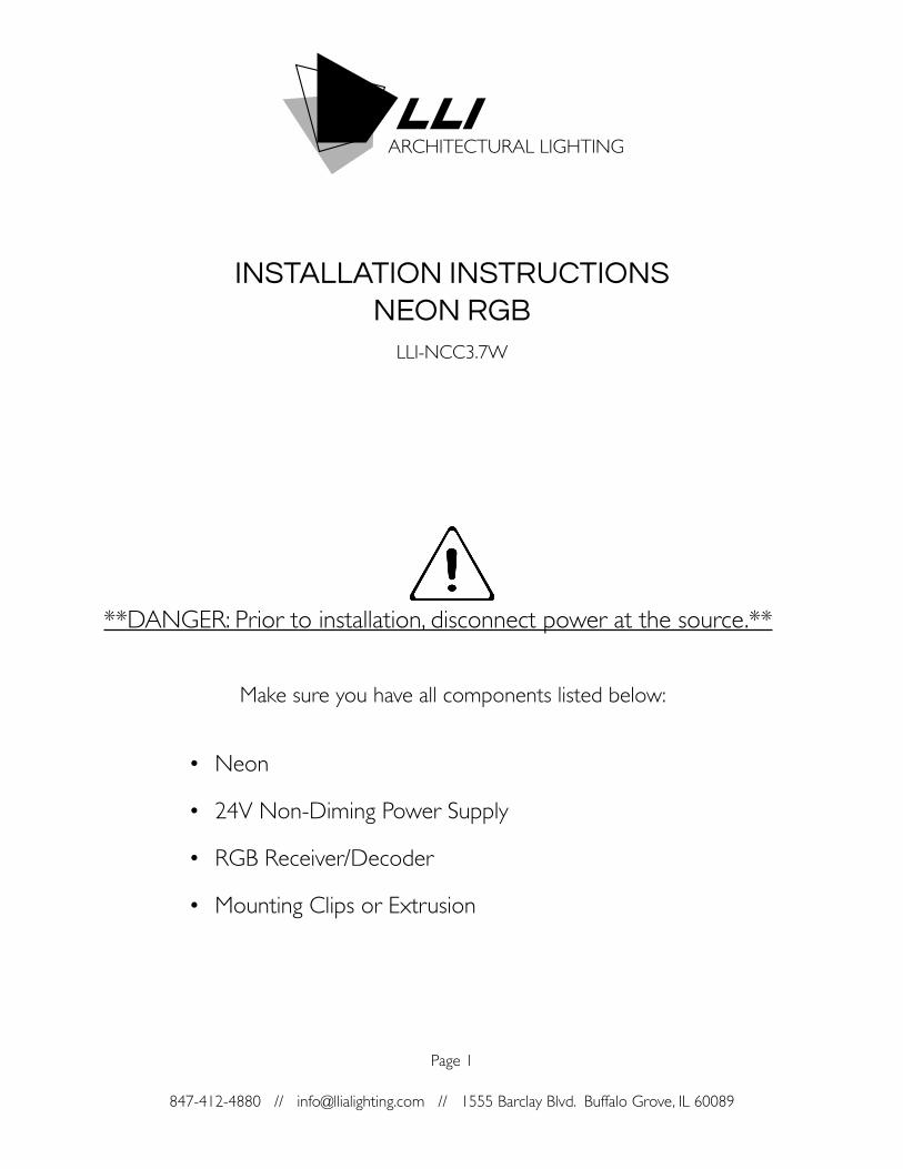
INSTALLATION INSTRUCTIONS NEON RGB
**DANGER: Prior to installation, disconnect power at the source.**
Make sure you have all components listed below:
• Neon
• 24V Non-Diming Power Supply
• RGB Receiver/Decoder
• Mounting Clips or Extrusion
Page 1
LLI-NCC3.7W

Please read all steps before beginning the installation.
847-412-4880 // [email protected] // 1555 Barclay Blvd. Buffalo Grove, IL 60089
INSTALLATION INSTRUCTIONS NEON RGB
• DANGER, RISK OF SHOCK: Prior to installation, disconnect power at the source.
• These products may represent a potential shock or fire hazard if improperly installed or attached in any way. Products should be installed in accordance with these instructions, local electrical codes and the National Electric Code (NEC).
• Do not connect directly to high voltage power (120-277V)!
• To avoid electrical shock, use only 24v hardwire or plug in power supply. Factory warranty will be void if used otherwise.
• Do not energize Neon when rolled up in a spool.
• LLI Architectural Lighting’s Neon is suitable for outdoor use and damp locations (IP65).
• Do not use if there is any damage to the unit or to the power cord’s insulation. Inspect periodically.
• Do not puncture, cut, shorten, or splice Neon. Consult factory at 847-412-4880 or [email protected] for custom configurations.
• Do not route cords or Neon through walls, doors, windows or any similar part of a building structure.
• Do not secure Neon or its power cord with staples, nails, or any other sharp objects that may cause damage. Mounting clips are available (sold separately).
• Do not install Neon closer than 6” to combustible material.
• Ensure applicable wires are in compliance with local codes (In-wall rated, wet-location, high temperature, etc.).
Page 2
847-412-4880 // [email protected] // 1555 Barclay Blvd. Buffalo Grove, IL 60089847-412-4880 // [email protected] // 1555 Barclay Blvd. Buffalo Grove, IL 60089
INSTALLATION INSTRUCTIONS NEON RGB
Page 3
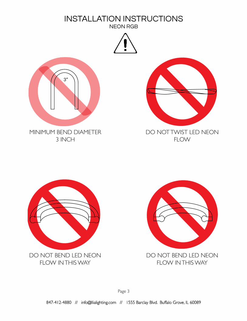
MINIMUM BEND DIAMETER3 INCH
DO NOT BEND LED NEON FLOW IN THIS WAY
DO NOT TWIST LED NEON FLOW
DO NOT BEND LED NEON FLOW IN THIS WAY
1 1/2”3”

847-412-4880 // [email protected] // 1555 Barclay Blvd. Buffalo Grove, IL 60089
INSTALLATION INSTRUCTIONS NEON RGB
Page 4
Remove the Neon from its package and un-roll the Neon.
Fasten mounting clips/channel onto mounting surface using appropriate hardware.
Measure the location where the Neon will be placed.
Carefully press the Neon into the support channel or mounting clips until secure.
NOTE: Do not bend the Neon tighter than a 1.5” radius (3” diameter).
STEP 1
STEP 3
STEP 2
STEP 4

847-412-4880 // [email protected] // 1555 Barclay Blvd. Buffalo Grove, IL 60089
INSTALLATION INSTRUCTIONS NEON RGB
Page 5
NOTE: Connect the positive wire from the power supply to the positive (+) wire on the Neon. Connect the negative (-) wire from the power supply to the negative wire on the Neon. Please make sure you always connect to the correct polarity. Each section is marked with a (+)
for positive and a (-) for negative. If a section does not energize, you may need to check the connector or switch the wires.
Open both wiring compartments on each end of the RGB Receiver/Decoder.
Connect the RGB wires from the Neon to the output terminals of the Receiver/Decoder. Connect the positive (+) wire to the positive (V+) input terminal, and connect the color wires to the corresponding color negative (-) input terminals.
Connect the positive (+) wire from the power supply to the positive (+) input terminal of the receiver. Connect negative (-) wire from the power supply to the negative (-) input terminal of the Receiver/Decoder.
STEP 14
STEP 16
STEP 15
Connect the power supply to AC power/line voltage. Please refer to the wiring diagram of the power supply being used. Each power supply has its own specific wiring. Once connected, turn on the Neon.
STEP 17
IMPORTANT: Polarity is crucial for the operation of the Neon. Please ensure that your wiring corresponds with the polarity of the Neon.
847-412-4880 // [email protected] // 1555 Barclay Blvd. Buffalo Grove, IL 60089
INSTALLATION INSTRUCTIONS NEON RGB
Page 6
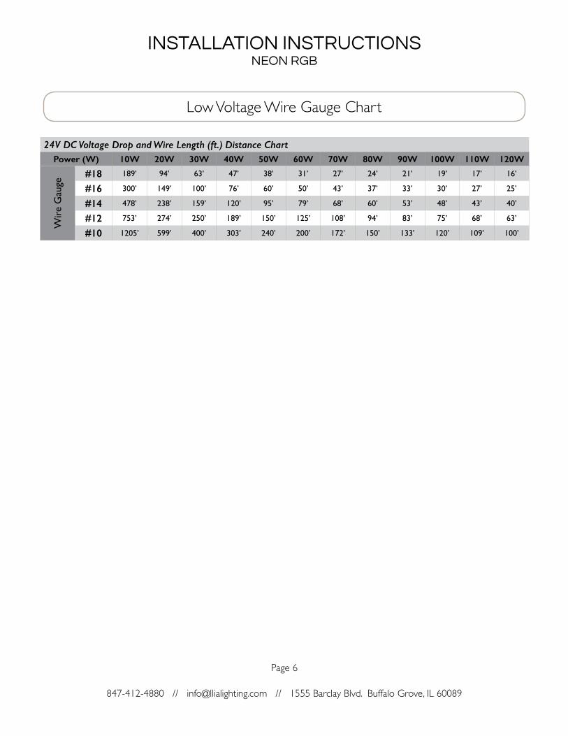
Low Voltage Wire Gauge Chart
24V DC Voltage Drop and Wire Length (ft.) Distance ChartPower (W) 10W 20W 30W 40W 50W 60W 70W 80W 90W 100W 110W 120W
Wir
e G
auge
#18 189’ 94’ 63’ 47’ 38’ 31’ 27’ 24’ 21’ 19’ 17’ 16’
#16 300’ 149’ 100’ 76’ 60’ 50’ 43’ 37’ 33’ 30’ 27’ 25’
#14 478’ 238’ 159’ 120’ 95’ 79’ 68’ 60’ 53’ 48’ 43’ 40’
#12 753’ 274’ 250’ 189’ 150’ 125’ 108’ 94’ 83’ 75’ 68’ 63’
#10 1205’ 599’ 400’ 303’ 240’ 200’ 172’ 150’ 133’ 120’ 109’ 100’