installation instructions rgb / rgbw 24v led tape...led tape into the connector. be sure to guide...
TRANSCRIPT

847-412-4880 // [email protected] // 1555 Barclay Blvd. Buffalo Grove, IL 60089
INSTALLATION INSTRUCTIONS RGB / RGBW 24V LED TAPE
LLI-LCC4.4WLLI-LCC5.9W
LLI-LCCW4.4WLLI-LCCW5.8WLLI-LTPCC4.4W
**DANGER: Prior to installation, disconnect power at the source.**
Make sure you have all components listed below:
• LED tape
• 24VDC Power Supply
• Connectors (if creating DIY connections)
• Extrusion/Lens (optional)
Page 1

Please read all steps before beginning the installation.
847-412-4880 // [email protected] // 1555 Barclay Blvd. Buffalo Grove, IL 60089
INSTALLATION INSTRUCTIONS RGB / RGBW 24V LED TAPE
• WARNING: Do not connect directly to high voltage power (120v-277v). Use only with 24V DC hardwire or plug-in power supply. Factory warranty will be void is used otherwise.
• These products may represent a potential shock or fire hazard if improperly installed or attached in any way. Products should be installed in accordance with these instructions, local electrical codes and the National Electric Code (NEC).
• Do not energize LED tape light when rolled up in its spool.
• Uncoated products are intended for indoor use in dry locations. Coated products are intended for outdoor use or in damp/wet locations. Refer to product spec sheet for location ratings.
• Do not use if there is any damage to the unit or to the wiring/insulation. Inspect periodically.
• Do not route cords or LED tape through walls, doors, windows or any similar part of a building structure.
• Do not secure LED tape or its power cord with staples, nails, or any other sharp objects that may cause damage. Mounting adhesive is available (sold separately).
• Do not install LED tape closer than 6” to combustible material.
• Ensure proper gauge wires are installed between Power Supplies, Controls & LED tape to avoid voltage drop.
• Ensure applicable wires are in compliance with local codes (In-wall rated, wet-location, high temperature, etc.).
• Recommended load for power supplies is 80%.
Page 2

847-412-4880 // [email protected] // 1555 Barclay Blvd. Buffalo Grove, IL 60089847-412-4880 // [email protected] // 1555 Barclay Blvd. Buffalo Grove, IL 60089
INSTALLATION INSTRUCTIONS RGB / RGBW 24V LED TAPE
1.5”
MINIMUM BEND RADIUS1.5 INCH
DO NOT FOLD OR CREASE LED TAPE
DO NOT COVER LED TAPE OR APPLY EXCESS PRESSURE TO
LED TAPE
DO NOT BEND LED TAPE SIDE TO SIDE
Page 3

Remove the LED tape spool from its package and un-roll the LEDs.
Cut the Linear LED to the desired length. Make sure you cut along the marked line and that the cut is straight.
Measure the location where the LED tape will be placed and identify the cut point of the LED tape. The cut point will be marked with a black line, and/or a small scissors image.
Peel back about a ¼ inch of the red backing and the adhesive tape. Make sure to expose the copper pads on the back of the Linear LED.
NOTE: This product can be interconnected and energized by soldering leads to the copper pads.
STEP 1
STEP 3
STEP 2
STEP 4
Prep LED Tape for Installation
847-412-4880 // [email protected] // 1555 Barclay Blvd. Buffalo Grove, IL 60089
INSTALLATION INSTRUCTIONS RGB / RGBW 24V LED TAPE
Page 4
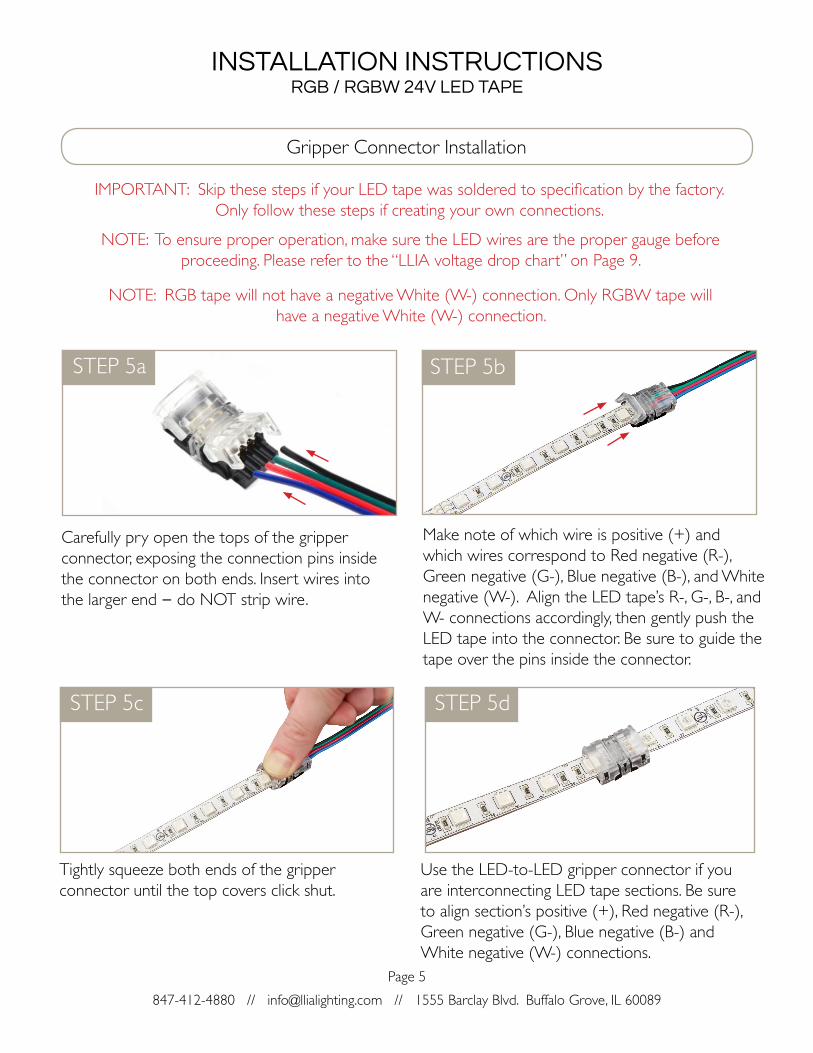
Gripper Connector Installation
Make note of which wire is positive (+) and which wires correspond to Red negative (R-), Green negative (G-), Blue negative (B-), and White negative (W-). Align the LED tape’s R-, G-, B-, and W- connections accordingly, then gently push the LED tape into the connector. Be sure to guide the tape over the pins inside the connector.
STEP 5c
STEP 5b
847-412-4880 // [email protected] // 1555 Barclay Blvd. Buffalo Grove, IL 60089
INSTALLATION INSTRUCTIONS RGB / RGBW 24V LED TAPE
STEP 5a
STEP 5d
IMPORTANT: Skip these steps if your LED tape was soldered to specification by the factory. Only follow these steps if creating your own connections.
NOTE: To ensure proper operation, make sure the LED wires are the proper gauge before proceeding. Please refer to the “LLIA voltage drop chart” on Page 9.
Carefully pry open the tops of the gripper connector, exposing the connection pins inside the connector on both ends. Insert wires into the larger end – do NOT strip wire.
Tightly squeeze both ends of the gripper connector until the top covers click shut.
Use the LED-to-LED gripper connector if you are interconnecting LED tape sections. Be sure to align section’s positive (+), Red negative (R-), Green negative (G-), Blue negative (B-) and White negative (W-) connections.
NOTE: RGB tape will not have a negative White (W-) connection. Only RGBW tape will have a negative White (W-) connection.
Page 5

Installation without Channel/Lens
STEP 6 STEP 7
847-412-4880 // [email protected] // 1555 Barclay Blvd. Buffalo Grove, IL 60089
INSTALLATION INSTRUCTIONS RGB / RGBW 24V LED TAPE
Remove the red adhesive backing from the LED tape.
Carefully press the LED tape to the mounting surface. Secure lead wire from connector.
IMPORTANT: Prior to mounting the LED tape, please ensure the surface is clean and free of any loose debris.
Page 6
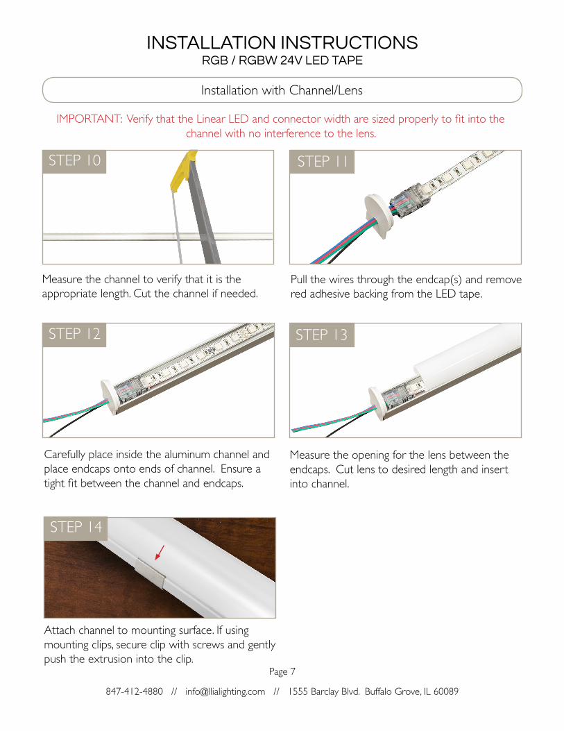
Installation with Channel/Lens
IMPORTANT: Verify that the Linear LED and connector width are sized properly to fit into the channel with no interference to the lens.
STEP 10
STEP 12
STEP 11
STEP 13
847-412-4880 // [email protected] // 1555 Barclay Blvd. Buffalo Grove, IL 60089
INSTALLATION INSTRUCTIONS RGB / RGBW 24V LED TAPE
Measure the channel to verify that it is the appropriate length. Cut the channel if needed.
Carefully place inside the aluminum channel and place endcaps onto ends of channel. Ensure a tight fit between the channel and endcaps.
Pull the wires through the endcap(s) and remove red adhesive backing from the LED tape.
Measure the opening for the lens between the endcaps. Cut lens to desired length and insert into channel.
Attach channel to mounting surface. If using mounting clips, secure clip with screws and gently push the extrusion into the clip.
STEP 14
Page 7

847-412-4880 // [email protected] // 1555 Barclay Blvd. Buffalo Grove, IL 60089
INSTALLATION INSTRUCTIONS RGB / RGBW 24V LED TAPE
IMPORTANT: Polarity is crucial for the operation of the RGB(W) LED tape. Please ensure that your wiring corresponds with the polarity of each copper pad.
Open both wiring compartments on each end of the 4-channel receiver.
Power Supply & Receiver Setup
Connect the wires from the RGB(W) Linear LED to the output terminals of the receiver. Connect the positive (+) wire to the positive (+) input terminal, and connect the color wires to the corresponding color negative (-) input terminals.
NOTE: Refer to the controller/receiver installation guides for more detail on connection and control of your RGB(W) LED tape.
Connect the positive (+) wire from the power supply to the positive (+) input terminal of the receiver. Connect negative (-) wire from the power supply to the negative (-) input terminal of the receiver.
NOTE: Verify that the power supply you are installing has the proper input and output voltage.
STEP 14
STEP 16
STEP 15
Connect the power supply to AC power/line voltage. Please refer to the wiring diagram of the power supply being used. Each power supply has its own specific wiring.
STEP 17
Page 8

INSTALLATION INSTRUCTIONS RGB / RGBW 24V LED TAPE
Low Voltage Wire Gauge Chart
847-412-4880 // [email protected] // 1555 Barclay Blvd. Buffalo Grove, IL 60089
24V DC Voltage Drop and Wire Length (ft.) Distance ChartPower (W) 10W 20W 30W 40W 50W 60W 70W 80W 90W 100W 110W 120W
Wir
e G
auge
#18 189’ 94’ 63’ 47’ 38’ 31’ 27’ 24’ 21’ 19’ 17’ 16’
#16 300’ 149’ 100’ 76’ 60’ 50’ 43’ 37’ 33’ 30’ 27’ 25’
#14 478’ 238’ 159’ 120’ 95’ 79’ 68’ 60’ 53’ 48’ 43’ 40’
#12 753’ 274’ 250’ 189’ 150’ 125’ 108’ 94’ 83’ 75’ 68’ 63’
#10 1205’ 599’ 400’ 303’ 240’ 200’ 172’ 150’ 133’ 120’ 109’ 100’
Page 9