installation instructions - todd's...
TRANSCRIPT

CRHEATER101A00 -- CRHEATER119A00,CRHEATER264A00 -- CRHEATER269A00,CRHEATER288A00 -- CRHEATER299A00CRHEATER301A00, CRHEATER308A00CRHEATER316A00 -- CRHEATER322A00CRSINGLE037A00 -- CRSINGLE054A00
Installation Instructions
SMALL ROOFTOP UNITSACCESSORY ELECTRIC HEATER
AND SINGLE POINT BOXELECTRIC COOLINGAND HEAT PUMP
SELECT 3 to 15 TONS
TABLE OF CONTENTSSAFETY CONSIDERATIONS 1. . . . . . . . . . . . . . . . . . . . . . . . .
PACKAGE USAGE 2. . . . . . . . . . . . . . . . . . . . . . . . . . . . . . . . . .
PACKAGE CONTENTS 2. . . . . . . . . . . . . . . . . . . . . . . . . . . . . .
GENERAL 6. . . . . . . . . . . . . . . . . . . . . . . . . . . . . . . . . . . . . . . . .
GENERAL INSTALLATION SEQUENCE 9. . . . . . . . . . . . . . . .
SECTION 1 INSTALLATION, SMALL--MEDIUM CABINET 10
Installing Single Point Box (CRSINGLE037A00--054A00) 10. . . . . . . . . . . . . . . . . . . . . . . . . . . . . . . . . . . . . . .
Installing Electric Heater (CRHEATER101A00--119A00,CRHEATER264A00--269A00, 297A00--299A00, 301A00,308A00, CRHEATER316A00--322A00) 10. . . . . . . . . . . . .
SECTION 2 INSTALLATION, LARGE CABINET (3 OUT-DOOR FANS) 18. . . . . . . . . . . . . . . . . . . . . . . . . . . . . . . . . . . . .
Installing Single Point Box (CRSINGLE047A00,049A00--054A00 18. . . . . . . . . . . . . . . . . . . . . . . . . . . . . . . .
Installing Electric Heater (CRHEATER288A00--296A00) 20. . . . . . . . . . . . . . . . . . . . . . . . . . . . . . . . . . . . . . .
UNIT POWER SUPPLY WIRING -- ALL UNITS 29. . . . . . . . .
APPENDIX A: CONNECTION FIGURES, AC--1, AC--2 31. . .
APPENDIX B: CONNECTION FIGURES, AC--3 42. . . . . . . . .
APPENDIX C: CONNECTION FIGURES, HP--1, HP2 49. . . . .
APPENDIX D: HEATER DATA 67. . . . . . . . . . . . . . . . . . . . . . .
IMPORTANT: Read these instructions completely beforeattempting to install this accessory.
SAFETY CONSIDERATIONSInstallation and servicing of air--conditioning equipmentcan be hazardous due to system pressure and electricalcomponents. Only trained and qualified service personnelshould install, repair, or service air-conditioningequipment.Untrained personnel can perform the basic maintenancefunctions. All other operations should be performed bytrained service personnel.
When working on air-conditioning equipment, observeprecautions in the literature, tags and labels attached tothe unit, and other safety precautions that may apply.Follow all safety codes. Wear safety glasses and workgloves.Recognize safety information. This is the safety--alert
symbol . When you see this symbol on the unit and ininstructions or manuals, be alert to the potential forpersonal injury.Understand the signal words DANGER, WARNING, andCAUTION. These words are used with the safety--alertsymbol. DANGER identifies the most serious hazardswhich will result in severe personal injury or death.WARNING signifies a hazard which could result inpersonal injury or death. CAUTION is used to identifyunsafe practices which may result in minor personalinjury or product and property damage. NOTE is used tohighlight suggestions which will result in enhancedinstallation, reliability, or operation.
ELECTRICAL SHOCK HAZARD
Failure to follow this warning could result in personalinjury or death.
Turn off all power to unit and install lockout tag.Power can come to unit from multiple sources. Verifypower is off with a meter or probe.
! WARNING
CUT HAZARD
Failure to follow this caution may result in personalinjury. Sheet metal parts may have sharp edges orburrs. Use care and wear appropriate protectiveclothing, safety glasses and gloves when handlingparts and servicing units.
CAUTION!
2
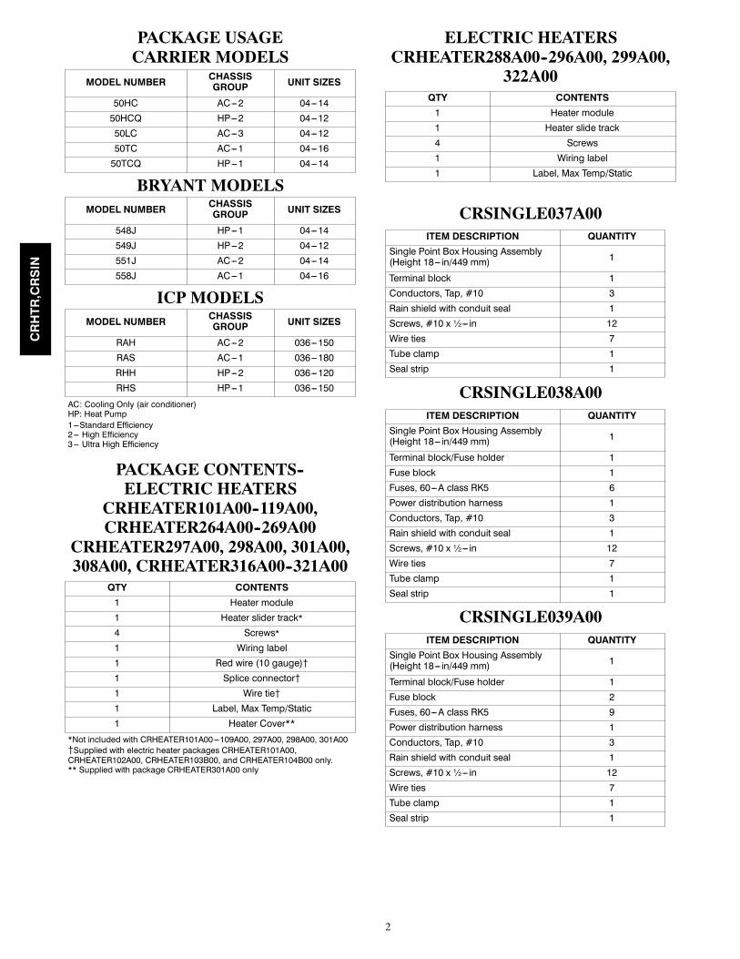
PACKAGE USAGECARRIER MODELS
MODEL NUMBER CHASSISGROUP UNIT SIZES
50HC AC---2 04---1450HCQ HP---2 04---1250LC AC---3 04---1250TC AC---1 04---1650TCQ HP---1 04---14
BRYANT MODELSMODEL NUMBER CHASSIS
GROUP UNIT SIZES
548J HP---1 04---14549J HP---2 04---12551J AC---2 04---14558J AC---1 04---16
ICP MODELSMODEL NUMBER CHASSIS
GROUP UNIT SIZES
RAH AC---2 036---150RAS AC---1 036---180RHH HP---2 036---120RHS HP---1 036---150
AC: Cooling Only (air conditioner)HP: Heat Pump1---Standard Efficiency2--- High Efficiency3--- Ultra High Efficiency
PACKAGE CONTENTS--ELECTRIC HEATERS
CRHEATER101A00--119A00,CRHEATER264A00--269A00
CRHEATER297A00, 298A00, 301A00,308A00, CRHEATER316A00--321A00
QTY CONTENTS1 Heater module1 Heater slider track*4 Screws*1 Wiring label1 Red wire (10 gauge){1 Splice connector{1 Wire tie{1 Label, Max Temp/Static1 Heater Cover**
*Not included with CRHEATER101A00---109A00, 297A00, 298A00, 301A00{Supplied with electric heater packages CRHEATER101A00,CRHEATER102A00, CRHEATER103B00, and CRHEATER104B00 only.** Supplied with package CRHEATER301A00 only
ELECTRIC HEATERSCRHEATER288A00--296A00, 299A00,
322A00QTY CONTENTS1 Heater module1 Heater slide track4 Screws1 Wiring label1 Label, Max Temp/Static
CRSINGLE037A00ITEM DESCRIPTION QUANTITY
Single Point Box Housing Assembly(Height 18--- in/449 mm) 1
Terminal block 1Conductors, Tap, #10 3Rain shield with conduit seal 1Screws, #10 x ½--- in 12Wire ties 7Tube clamp 1Seal strip 1
CRSINGLE038A00ITEM DESCRIPTION QUANTITY
Single Point Box Housing Assembly(Height 18--- in/449 mm) 1
Terminal block/Fuse holder 1Fuse block 1Fuses, 60---A class RK5 6Power distribution harness 1Conductors, Tap, #10 3Rain shield with conduit seal 1Screws, #10 x ½--- in 12Wire ties 7Tube clamp 1Seal strip 1
CRSINGLE039A00ITEM DESCRIPTION QUANTITY
Single Point Box Housing Assembly(Height 18--- in/449 mm) 1
Terminal block/Fuse holder 1Fuse block 2Fuses, 60---A class RK5 9Power distribution harness 1Conductors, Tap, #10 3Rain shield with conduit seal 1Screws, #10 x ½--- in 12Wire ties 7Tube clamp 1Seal strip 1
CRHTR,CRSIN

3
CRSINGLE040A00ITEM DESCRIPTION QUANTITY
Single Point Box Housing Assembly(Height 18--- in/449 mm) 1
Terminal block/Fuse holder 1Fuse block 1Fuses, 60---A class RK5 4Power distribution harness 1Conductors, Tap, #10 2Rain shield with conduit seal 1Screws, #10 x ½--- in 12Wire ties 7Tube clamp 1Seal strip 1
CRSINGLE041A00ITEM DESCRIPTION QUANTITY
Single Point Box Housing Assembly(Height 18--- in/449 mm) 1
Terminal block/Fuse holder 1Fuse block 1Fuses, 60---A class RK5 6Power distribution harness 1Conductors, Tap, #10 2Rain shield with conduit seal 1Screws, #10 x ½--- in 12Wire ties 7Tube clamp 1Seal strip 1
CRSINGLE042A00ITEM DESCRIPTION QUANTITY
Single Point Box Housing Assembly(Height 25--- in/639 mm) 1
Terminal block 1Conductors, Tap, #10 3Rain shield with conduit seal 1Screws, #10 x ½--- in 8Wire ties 7Seal strip 1
CRSINGLE043A00ITEM DESCRIPTION QUANTITY
Single Point Box Housing Assembly(Height 25--- in/639 mm) 1
Terminal block/Fuse holder 1Fuse block 1Terminal block (TB---10) 2Fuses, 60---A class RK5 6Power distribution harness 1Conductors, Tap, #10 6Screws, #8 x ½--- in 2Rain shield with conduit seal 1Screws, #10 x ½--- in 8Wire ties 7Seal strip 1
CRSINGLE044A00ITEM DESCRIPTION QUANTITY
Single Point Box Housing Assembly(Height 25--- in/639 mm) 1
Terminal block 1Fuse block 2Fuses, 60---A class T (600v) 6Power distribution harness 1Conductors, Tap, #10 3Rain shield with conduit seal 1Screws, #10 x ½--- in 8Wire ties 7Seal strip 1
CRSINGLE045A00ITEM DESCRIPTION QUANTITY
Single Point Box Housing Assembly(Height 25--- in/639 mm) 1
Terminal block/fuse holder 1Fuse block 2Fuses, 60---A class RK5 9Power distribution harness 1Conductors, Tap, #10 6Terminal block (TB10) 2Screws, #8 x ½--- in 2Rain shield with conduit seal 1Screws, #10 x ½--- in 8Wire ties 7Seal strip 1
CRSINGLE046A00ITEM DESCRIPTION QUANTITY
Single Point Box Housing Assembly(Height 25--- in/639 mm) 1
Terminal block/fuse holder 1Fuse block 3Fuses, 60---A class RK5 12Power distribution harness 1Conductors, Tap, #10 3Rain shield with conduit seal 1Screws, #10 x ½--- in 8Wire ties 7Seal strip 1
CRSINGLE047A00ITEM DESCRIPTION QUANTITY
Single Point Box Housing Assembly(Height 33--- in/845 mm) 1
Terminal block 1Conductors, Tap, #10 3Rain shield, small 1Rain shield with conduit seal 1Screws, #10 x ½--- in 8Wire ties 7Seal strip 1
CRHTR,CRSIN

4
CRSINGLE048A00ITEM DESCRIPTION QUANTITY
Single Point Box Housing Assembly(Height 25--- in/639 mm) 1
Terminal block 1Fuse block 3Fuses, 60---A class RK5 9Power distribution harness 1Conductors, Tap, #10 3Rain shield with conduit seal 1Screws, #10 x ½--- in 8Wire ties 7Seal strip 1
CRSINGLE049A00ITEM DESCRIPTION QUANTITY
Single Point Box Housing Assembly(Height 33--- in/845 mm) 1
Terminal block/Fuse holder 1Fuse block 1Fuses, 60---A class RK5 6Power distribution harness 1Conductors, Tap, #10 8Terminal block (TB10) 2Screws, #8 x ½--- in 2Rain shield, small 1Rain shield with conduit seal 1Screws, #10 x ½--- in 8Wire ties 7Seal strip 1
CRSINGLE050A00ITEM DESCRIPTION QUANTITY
Single Point Box Housing Assembly(Height 33--- in/845 mm) 1
Terminal block 1Fuse block 2Fuses, 60---A class T (600v) 6Power distribution harness 1Conductors, Tap, #10 3Rain shield, small 1Rain shield with conduit seal 1Screws, #10 x ½--- in 8Wire ties 7Seal strip 1
CRSINGLE051A00ITEM DESCRIPTION QUANTITY
Single Point Box Housing Assembly(Height 33--- in/845 mm) 1
Terminal block/fuse holder 1Fuse block 2Fuses, 60---A class RK5 9Power distribution harness 1Conductors, Tap, #10 8Terminal block (TB10) 2Screws, #8 x ½--- in 2Rain shield, small 1Rain shield with conduit seal 1Screws, #10 x ½--- in 8Wire ties 7Seal strip 1
CRSINGLE052A00ITEM DESCRIPTION QUANTITY
Single Point Box Housing Assembly(Height 33--- in/845 mm) 1
Terminal block 1Fuse block 3Fuses, 60---A class T (600v) 9Power distribution harness 1Conductors, Tap, #10 3Rain shield, small 1Rain shield with conduit seal 1Screws, #10 x ½--- in 8Wire ties 7Seal strip 1
CRSINGLE053A00ITEM DESCRIPTION QUANTITY
Single Point Box Housing Assembly(Height 33--- in/845 mm) 1
Terminal block 1Fuse block 4Fuses, 60---A class RK5 12Power distribution harness 1Conductors, Tap, #10 8Terminal block (TB10) 2Screws, #8 x ½--- in 2Rain shield, small 1Rain shield with conduit seal 1Screws, #10 x ½--- in 8Wire ties 7Seal strip 1
CRHTR,CRSIN

5
CRSINGLE054A00ITEM DESCRIPTION QUANTITY
Single Point Box Housing Assembly(Height 33--- in/845 mm) 1
Terminal block 1Fuse block 5Fuses, 60---A class RK5 15Power distribution harness 1Conductors, Tap, #10 8Terminal block (TB10) 2Screws, #8 x ½--- in 2Rain shield, small 1Rain shield with conduit seal 1Screws, #10 x ½--- in 8Wire ties 7Seal strip 1
CRHTR,CRSIN

6
GENERALPuronR UnitsThis installation instruction manual describes theinstallation of electric heaters and associated fuseblock/field power termination kits (single point box orSPB) on small rooftop units in nominal cooling capacitiesfrom 3 to 15 tons. These rooftop units use Puronrefrigerant (R-410A). See Package Usage tables on page2 for applicable unit models. Unit types include coolingunits (AC) and heat pumps (HP) distributed over severalchassis sizes. Unit types AC--1, AC--2, HP--1, HP--2 areidentified. Unit type AC--3 consists of a single model —Carrier 50LC.This information does not include selection data. Refer toproject plans, job submittals and selection programs forheater and field power termination/SPB kit usage.Some electric heaters used on these Puron (R-410A) unitsmay also be installed in earlier R-22 rooftop units. Referto Form 50-8SI or IIK-548-36-49 for installationinstructions on heater packages CRHEATER101A00through 119A00 with earlier models. Contact your localdistributor office for a copy of this form.
Electric HeatersHeaters are shipped with one heater per carton. Thecarton is marked with a Sales Package Number. On allheaters except CRHEATER101A00 through 119A00, theheater Model Number (as marked on the heater infoplate)is the same as the Sales Package number. OnCRHEATER101A00 through 119A00 heaters, the value inposition 9 of the part number differs between the salespackage part number (value is 1) and bare heater modelnumber (value is 0). (See Table 1.)The heaters are modular in design, with heater framesholding open coil resistance wires strung through ceramicinsulators, limit switches and one or two controlcontactors. Power conductors are attached. One or twoheater modules may be used in a unit.Heater modules are installed in the compartment belowthe indoor (supply) fan outlet. Access is through theindoor access panel. Heater modules slide into thecompartment on tracks along the bottom of the heateropening. (See Fig. 15.)NOTE: The following heaters do not use the slide track --CRHEATER01A00--109A00, 297A00, 298A00, and301A00.
Not all available heater modules may be used in everyunit. Use only those heater modules that are UL listed foruse in a specific size unit. Refer to the label on the unitcabinet for the list of approved heaters. (See Fig. 1 and2.) See Appendix D for electric heater module data.
Single Point Boxes and FusesThe Single Point Box kits provide a field powertermination location plus an enclosure for heater fuseswhen required by code. The SPBs are installed under theunit’s main control box and include a cover plus allinternal wiring. Minimum components of the SPB are afield power terminal block with tap conductors (toconnect to the unit’s main control box field terminals).Maximum component population includes up to five fuseblocks.Fuses for electric heater circuits are required and providedwhen the unit’s MOCP exceeds 60-A or when the totalheater Full Load Amp value exceeds 48-A. When fusesare required and provided, the cooling circuit is alsoprovided with fuse protection; some units require minorwiring changes in the main control box (see section onTB10 terminal blocks).
No FusesIf the unit’s MOCP device rating is 60-A or less, then theMOCP device is recognized as providing the requiredovercurrent protection to the heater and no internal fusingis required. If two heater modules are installed, a singlepoint box that contains only a field power terminal blockis required. See tables at the beginning of Appendix A, Band C for where-used information on the single pointboxes and for connections Figure number.
Units with Factory Installed HACRThe amp rating of the HACR factory installed option isbased on the size, voltage, indoor motor and otherelectrical options of the unit as shipped from the factory.When field installed accessory electric heaters are addedor changed in the unit, the HACR may no longer be of theproper amp rating and therefore will need to be removedfrom the unit. See unit nameplate and label on factoryinstalled HACR for the amp rating of the HACR that wasshipped with the unit from the factory. See unitnameplates for the proper fuse, HACR or maximumover--current protection device required on the unit withfield installed electric heat.
Single Point Box ContentsSee Package Content tables for a list of componentsincluded in each single point box kit. Note the heightdifferences and their use in specific size units.
Control WiringHeater modules contain one or two heater controlcontactors. If two heater modules are installed, or atwo-circuit heater module is installed, the cooling unit(AC type) can be connected for one-stage or two-stageheating control. On all heat pump units (HP type), allheater contactors will be connected to providesecond-stage heating control.
CRHTR,CRSIN

7
Table 1 – Heater Model Number
Bare Heater ModelNumber C R H E A T E R 0 0 1 A 0 0
Heater Sales PackagePNOIncludes:Bare HeaterCarton and packingmaterialsInstallation sheet
C R H E A T E R 1 0 1 A 0 0
7310 West Morris StreetIndianapolis, IN 46231 U.S.A.
BREAKER PER NEC
MAX OVERCURRENT
MINIMUM UNIT DISCONNECT
FLA LRA
PROTECTION DEVICE
VOLT
OTHER
LBS kg
CAPACITY Btu/Hr CAPACITY kW EER COP
COOLING
HP HEATING
THIS EQUIPMENT COMPLIES WITH THE
2004 REQUIREMENTS OF ASHRAE 90.1
CarrierCorporation
MODEL
QTY VOLTS AC PH HZ RLA LRA REF. SYSTEM R410A TEST PRESSURE GAGE
COMPR A
COMPR B
LBS
LBS
kg
kg
HI
LO
PSI kPa
PSI kPa
FAN MTR QTY VOLTS AC PH HZ FLA
OUTDOOR
COMPR C
INDOOR
PWR.EXH.
ELC.HEATCHARGE SYSTEM PER INSTALLATION INSTRUCTIONS
SUITABLE FOR OUTDOOR INSTALLATION
POWER
SUPPLY PH HZ
PERMISSIBLEVOLTAGE AT UNIT MINMAX
DOWN SUPPLYMIN CLEARANCE TO COMBUSTIBLE MATERIALS _____INCHES ______mm.
FOR FIRST _____INCHES______mm. OF DUCT WHEN ELECTRIC HEATER IS INSTALLEDSIDE SUPPLY
MIN CLEARANCE TO COMBUSTIBLE MATERIALS _____INCHES ______mm.
FOR FIRST _____INCHES______mm. OF DUCT WHEN ELECTRIC HEATER IS INSTALLED
*FOR INSTALLATION ON COMBUSTIBLE FLOORING OR
CLASS A,B, OR C ROOFING MATERIAL
ACCESSORYHEATER MODEL
NUMBER
CHECK
HEREVOLTS PH HZ
HEATER FLA
MIN CKT AMPS
FUSE OR HACRBREAKERPER NEC
MAXIMUM OVERCURRENT PROTECTION DEVICE
SINGLE PT. BOX MODEL NUMBER
MINIMUM UNIT DISCONNECT
FLA LRA
INSTALLER NOTE: 1.INSTALL ACCESS HEATER PER INSTALL INSTR ENCLOSED WITH HEATER. MARKSPACE "CHECK HERE" FOR MODEL USED USE MIN CKT AMPS & MAX OVER-CURRENT DEVICE AMPS LISTED FOR HEATER. IF NO HEATER IS USEDMARK SPACE "CHECK HERE" FOR NONE.
2.HEATERS ARE MANUFACTURED BY EMERSON HEATING PRODUCTS OR TUTCO ELECTRIC.
MIN. CKT.AMPS
MAX FUSE OR HACR
50TC-A06A2A5A0A0A0
10.7 4.9 650 4482450 3103
1 208/230 3 60 15.6 110
1 208/230 1 60 1.51 208/230 3 60 5.2
208/230 3 60
253 187 26.2
40
26 144-
1 2512 305
1 2512 305
17.25900013
102A 208/240
3 60 13.6/15.6
26.2/26.2
40/40 -/- - 26/26 144/144
104B 208/240
3 60 21.9/25.3
33.9/38.1
40/40 -/- - 31/35 144/144
105A 208/240
3 60 33.4/38.5
48.3/54.6
50/60 -/- 037 44/50 144/144
104B+104B 208/240
3 60 43.8/50.5
61.3/69.6
70/70 -/- 038 56/64 144/144
104B+105A 208/240
3 60 55.2/63.8
75.5/86.3
80/90 -/- 038 69/79 144/144
C10531
Fig. 1 -- Unit Informative Data Label
CRHTR,CRSIN

8
BOX MODELNUMBER
SINGLE PTBOX MODELNUMBER
SINGLE PTBOX MODELNUMBER
1.INSTALL ACCESS. HEATER AND/OR POWER EXHAUST PER INSTALL INSTR ENCLOSED
USE MIN CKT AMPS AND MAX OVER CURRENT DEVICE AMPS LISTED FOR HEATER
HERE
CHECK
MODEL
REFRIGERANT CHARGE R410A
ELECTRICAL DATA FOR ACCESSORY POWER EXHAUST INSTALLED
IN COMBINATAION WITH ELECTRIC HEATER
ACCESSORYHEATER MODEL
NUMBER
HEATER
FLA
FLA
LRA
INSTALLER NOTE:
WITH HEATER AND POWER EXHAUST. MARKSPACE "CHECK HERE" FOR MODEL USED.
AND POWER EXHAUST.
2.HEATERS ARE MANUFACTURED BY EMERSON HEATING PRODUCTS OR TUTCO ELECTRIC.
ELECTRICAL DATA FOR ACCESSORY POWER EXHAUST ONLY
ACCESSORYPOWER EXHAUST
MODEL NUMBER
CHECK
HERE
VOLTS PH HZ MIN CKTAMPS
FUSE ORHACR
BREAKERPER NEC
MAXIMUMOVERCURRENTPOROTECTION
DEVICE
MINIMUMUNIT
DISCONNECT
FLA
LRA
FLA
EXHAUSTPOWER
FUSE ORHACR
BREAKERPER NEC
MAXIMUMOVERCURRENTPOROTECTION
DEVICE
MINIMUMUNIT
DISCONNECT
SINGLE PTBOX MODELNUMBER
FLA
LRA
FLA
LRA
FLA
LRA
FLA
LRA
FLA
LRA
VOLTS PH HZ MIN CKTAMPS
SINGLE PTBOX MODELNUMBER
SINGLE PTBOX MODELNUMBER
SINGLE PT
50TC-A06A2A5A0A0A0
28.128
146
-/-
-/-
-/-
-/-
-/-
40 -/-
40/40
40/45
60/60
70/80
80/90
146/146
CRPWREXH_
146/146
146/146
28/28
33/37
146/146
47/52
59/66
146/146
72/82
28.1/28.4
36.3/40.5
50.6/57.0
63.6/72.0
77.9/88.6
102A208/240
3 60 13.6/15.6
-
104B208/240
3 60 21.9/25.3
-
105A208/240
3 60 33.4/38.5
037
104B+104B208/240
3 60 43.8/50.5
038
104B+105A208/240
3 60 55.2/63.8
038
*50TC-A06A2A5A0A0A0**50TC-A06A2A5A0A0A0**50TC-A06A2A5A0A0A0**50TC-A06A2A5A0A0A0**50TC-A06A2A5A0A0A0**50TC-A06A2A5A0A0A0**50TC-A06A2A5A0A0A0**50TC-A06A2A5A0A0A0**50TC-A06A2A5A0A0A0**50TC-A06A2A5A0A0A0**50TC-A06A2A5A0A0A0**50TC-A06A2A5A0A0A0**50TC-A06A2A5A0A0A0**50TC-A06A2A5A0A0A0**50TC-A06A2A5A0A0A0**50TC-A06A2A5A0A0A0**50TC-A06A2A5A0A0A0**50TC-A06A2A5A0A0A0**50TC-A06A2A5A0A0A0**50TC-A06A2A5A0A0A0**50TC-A06A2A5A0A0A0**50TC-A06A2A5A0A0A0**50TC-A06A2A5A0A0A0**50TC-A06A2A5A0A0A0**50TC-A06A2A5A0A0A0**50TC-A06A2A5A0A0A0*
C10532
Fig. 2 -- Unit Informative Data Label, Power Exhaust Installed
CRHTR,CRSIN

9
Terminal Block TB10 (208/230--V Units)Two small terminal blocks (designated TB10) areincluded in these single--point boxes used on select208/230--3--60 units.
SPB PNO CRSINGLE_043A00045A00049A00051A00053A00054A00
TB10 is a small single--pole terminal block, 2--1/2--in. (63mm) long with seven ¼--in. male quick--connectterminals. One or two terminal blocks are used to aid inre--arranging the unit’s base cooling power circuit into twocircuits, each under 60--A MOCP. On units using bothTB10 blocks, the indoor fan motor is separated into thesecond circuit. On units using only a single TB10 block,Compressor 2 is separated into the second circuit.On the largest units and on all AC--3 (50LC) units, theTB10 blocks are not used and may be discarded. The tapconductors from fuse blocks FU2 and FU3 are connectedin parallel to the main control box’s power terminal block.See unit--SPB connection figures in the Appendix section.The following tables indicate TB10 use on AC--1, AC--2,HP--1 and HP--2 units using these single point boxes:
AC--1AC--1 SPB TB10 Qty
08 (090,091)043A045A
2
09 (101,102)049A051A
2
12 (120,121)049A051A
2
14 (150)049A051A
1
16 (180)049A051A053A
NR
AC--2AC--2 SPB TB10 Qty07 (072) 043A 2
08 (090)049A051A
2
09 (102)049A051A
2
12 (120)049A051A
1
14 (150)049A051A
NR
HP--1HP--1 SPB TB10 Qty
08 (090)049A051A053A
2
09 (102)049A051A053A
2
12 (120)
049A051A053A054A
1
14 (150)051A053A054A
NR
HP--2HP--2 SPB TB10 Qty
07 (072)043A045A
2
08 (090)049A051A053A
2
09 (102)
049A051A053A054A
1
12 (120)
049A051A053A054A
NR
GENERAL INSTALLATIONSEQUENCE
1. Pre--stage heater packages and single point boxes byplacing the required component cartons at each unit.
2. Check the heater sales package number and singlepoint box part number (if used) against the partnumbers on the unit’s infoplate. See Fig. 1 and 2 fortypical data.
3. Disconnect power wiring into unit control box fromfactory--installed disconnect switch or HACR break-er and withdraw wiring from control box.
4. Install the single point box and connect powerwiring tap conductors to field power terminals inmain control box.
5. Install the electric heater module(s) and connectheater power conductors to single point box or mainunit control box per appropriate connections figure.(See Appendix A, B and C.)
6. Connect the heater control contactors to unit termi-nal block TB4.
7. Mark the unit infoplate to indicate which heatermodule(s) have been installed.
CRHTR,CRSIN
10
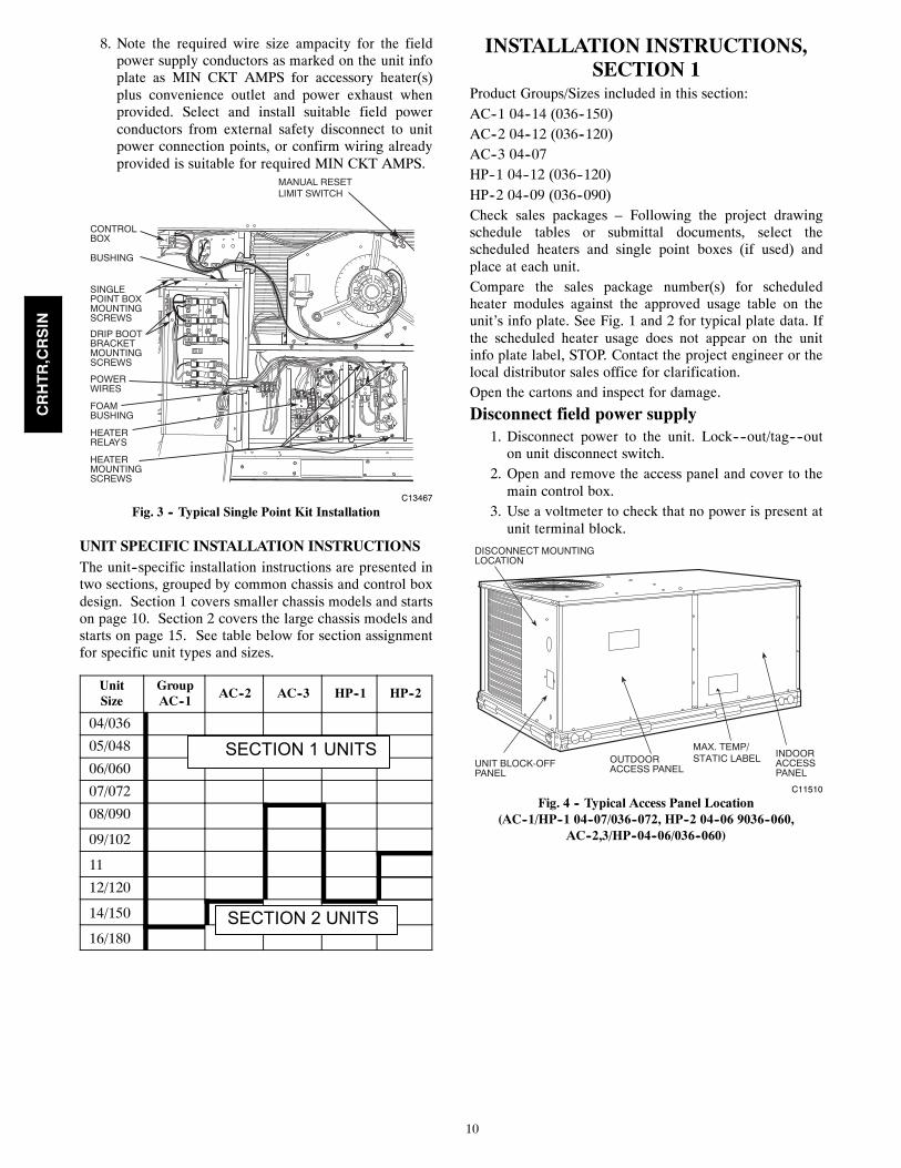
8. Note the required wire size ampacity for the fieldpower supply conductors as marked on the unit infoplate as MIN CKT AMPS for accessory heater(s)plus convenience outlet and power exhaust whenprovided. Select and install suitable field powerconductors from external safety disconnect to unitpower connection points, or confirm wiring alreadyprovided is suitable for required MIN CKT AMPS.
ALLIED PA
MODEL NO.
ERIAL NO.
CORP.
1113
2123
OD
22.2
3123
ISTED AIRNDITIONINGUIP ACCESS 346N.
P / N 2- 5610-4 REV
1113
2123
CONTROLBOX
BUSHING
SINGLEPOINT BOXMOUNTINGSCREWS
FOAMBUSHING
DRIP BOOTBRACKETMOUNTINGSCREWS
HEATERRELAYS
POWERWIRES
HEATERMOUNTINGSCREWS
MANUAL RESETLIMIT SWITCH
C13467
Fig. 3 -- Typical Single Point Kit Installation
UNIT SPECIFIC INSTALLATION INSTRUCTIONSThe unit--specific installation instructions are presented intwo sections, grouped by common chassis and control boxdesign. Section 1 covers smaller chassis models and startson page 10. Section 2 covers the large chassis models andstarts on page 15. See table below for section assignmentfor specific unit types and sizes.
UnitSize
GroupAC--1
AC--2 AC--3 HP--1 HP--2
04/036
05/048
06/060
07/072
08/090
09/102
11
12/120
14/150
16/180
INSTALLATION INSTRUCTIONS,SECTION 1
Product Groups/Sizes included in this section:AC--1 04--14 (036--150)AC--2 04--12 (036--120)AC--3 04--07HP--1 04--12 (036--120)HP--2 04--09 (036--090)Check sales packages – Following the project drawingschedule tables or submittal documents, select thescheduled heaters and single point boxes (if used) andplace at each unit.Compare the sales package number(s) for scheduledheater modules against the approved usage table on theunit’s info plate. See Fig. 1 and 2 for typical plate data. Ifthe scheduled heater usage does not appear on the unitinfo plate label, STOP. Contact the project engineer or thelocal distributor sales office for clarification.Open the cartons and inspect for damage.
Disconnect field power supply1. Disconnect power to the unit. Lock----out/tag----outon unit disconnect switch.
2. Open and remove the access panel and cover to themain control box.
3. Use a voltmeter to check that no power is present atunit terminal block.
DISCONNECT MOUNTINGLOCATION
UNIT BLOCK-OFFPANEL
OUTDOORACCESS PANEL
INDOORACCESSPANEL
MAX. TEMP/STATIC LABEL
C11510
Fig. 4 -- Typical Access Panel Location(AC--1/HP--1 04--07/036--072, HP--2 04--06 9036--060,
AC--2,3/HP--04--06/036--060)
CRHTR,CRSIN
SECTION 1 UNITS
SECTION 2 UNITS

11
DISCONNECT MOUNTINGLOCATION
UNITBLOCK-OFFPANEL
OUTDOORACCESS PANEL
INDOORACCESSPANELMAX. TEMP/
STATIC LABEL
C11511
Fig. 5 -- Typical Access Panel Location(AC--1 08--14/090--150, AC--2 07--12/072--120,AC--3 07,
HP--1 08--23/090--120, HP--2 07--09/072--102)
HEATERMOUNTINGBRACKET
HEATERMODULE(LOCATION 2)
HEATERMODULE(LOCATION 1)
SINGLE POINT BOX(NOT SHIPPED WITHUNIT)
HEATERCOVERS
MAINCONTROLBOX
CENTERPOST
C11514
(All units except large [3 outdoor fan] cabinet)
Fig. 6 -- Typical Component Location
4. Remove control box cover and center post. Savescrews. (See Fig. 6.)
5. If unit does not have the factory--installed discon-nect or HACR option or has not had field powerwiring connected, skip to Step 6.When unit is equipped with factory--installed dis-connect or HACR or has field power wiring connec-ted, disconnect the power leads at the control boxterminals and withdraw the conductors from thecontrol box.
6. Add seal strip to the rear bottom corner of the con-trol panel as shown in Fig. 7. Foil tape open screwholes on the back of the single point box as shownin Fig. 7. Different single point boxes will have dif-ferent screw holes open.
7. All bushings in the area of the control box wherethe single point box (SPB) mounts, must be re-moved prior to securing the SPB to the control box.(See Fig. 8.) Also, for units installed in the snowbelt, all unplugged holes in the bottom of the con-
trol box which are not used must be plugged beforeinstalling the SPB. Use foil tape or reinstall thebushings from the outside of the control box prior tosecuring the SPB. (See Fig. 9.)
8. Remove the single point box cover. Secure singlepoint box to the underside of the control box withthe 2 screws provided. (See Fig. 3.) Re--install bush-ing on the SPB tap conductors. (See Fig. 9.)
9. Secure the rainshield (conduit drip boot bracket) as-sembly to the back of the single point box with 2 ofthe screws provided. (See Fig. 3.) The channel por-tion of the bracket assembly extends to the top pan-el behind the control box. Secure all wires to brack-et with field--supplied wire tie as shown. (See Fig.13.)
Seal Bottom Corner
Seal Back Corner
Foil Tape LocationsC101085
Fig. 7 -- Seal Strip and Foil Tape Locations
C09005
Fig. 8 -- Control Box -- Bushings to Remove
CRHTR,CRSIN
12
C09006
Fig. 9 -- Bushings Replaced from Outside Control Box
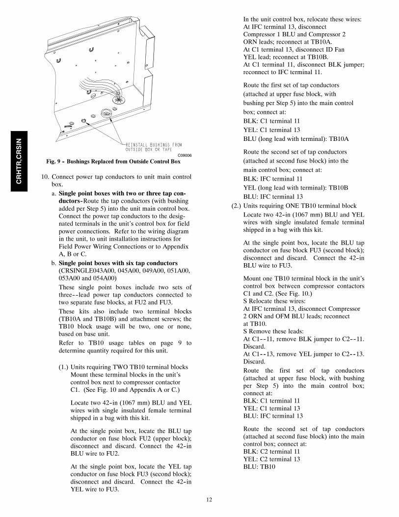
10. Connect power tap conductors to unit main controlbox.a. Single point boxes with two or three tap con-ductors--Route the tap conductors (with bushingadded per Step 5) into the unit main control box.Connect the power tap conductors to the desig-nated terminals in the unit’s control box for fieldpower connections. Refer to the wiring diagramin the unit, to unit installation instructions forField Power Wiring Connections or to AppendixA, B or C.
b. Single point boxes with six tap conductors(CRSINGLE043A00, 045A00, 049A00, 051A00,053A00 and 054A00)These single point boxes include two sets ofthree----lead power tap conductors connected totwo separate fuse blocks, at FU2 and FU3.These kits also include two terminal blocks(TB10A and TB10B) and attachment screws; theTB10 block usage will be two, one or none,based on base unit.Refer to TB10 usage tables on page 9 todetermine quantity required for this unit.
(1.) Units requiring TWO TB10 terminal blocksMount these terminal blocks in the unit’scontrol box next to compressor contactorC1. (See Fig. 10 and Appendix A or C.)
Locate two 42--in (1067 mm) BLU and YELwires with single insulated female terminalshipped in a bag with this kit.
At the single point box, locate the BLU tapconductor on fuse block FU2 (upper block);disconnect and discard. Connect the 42--inBLU wire to FU2.
At the single point box, locate the YEL tapconductor on fuse block FU3 (second block);disconnect and discard. Connect the 42--inYEL wire to FU3.
In the unit control box, relocate these wires:At IFC terminal 13, disconnectCompressor 1 BLU and Compressor 2ORN leads; reconnect at TB10A.At C1 terminal 13, disconnect ID FanYEL lead; reconnect at TB10B.At C1 terminal 11, disconnect BLK jumper;reconnect to IFC terminal 11.
Route the first set of tap conductors(attached at upper fuse block, withbushing per Step 5) into the main controlbox; connect at:BLK: C1 terminal 11YEL: C1 terminal 13BLU (long lead with terminal): TB10A
Route the second set of tap conductors(attached at second fuse block) into themain control box; connect at:BLK: IFC terminal 11YEL (long lead with terminal): TB10BBLU: IFC terminal 13
(2.) Units requiring ONE TB10 terminal blockLocate two 42--in (1067 mm) BLU and YELwires with single insulated female terminalshipped in a bag with this kit.
At the single point box, locate the BLU tapconductor on fuse block FU3 (second block);disconnect and discard. Connect the 42--inBLU wire to FU3.
Mount one TB10 terminal block in the unit’scontrol box between compressor contactorsC1 and C2. (See Fig. 10.)S Relocate these wires:At IFC terminal 13, disconnect Compressor2 ORN and OFM BLU leads; reconnectat TB10.S Remove these leads:At C1----11, remove BLK jumper to C2----11.Discard.At C1----13, remove YEL jumper to C2----13.Discard.Route the first set of tap conductors(attached at upper fuse block, with bushingper Step 5) into the main control box;connect at:BLK: C1 terminal 11YEL: C1 terminal 13BLU: IFC terminal 13
Route the second set of tap conductors(attached at second fuse block) into the maincontrol box; connect at:BLK: C2 terminal 11YEL: C2 terminal 13BLU: TB10
CRHTR,CRSIN

13
(3.) Units requiring NO TB10 terminal block
Route the first set of tap conductors(attached at upper fuse block, with bushingper Step 5) into the main control box.
Route the second set of tap conductors(attached at second fuse block) into the maincontrol box.
Connect both sets of tap conductors to unitterminal block TB1; connect at:BLK: terminal 11YEL: terminal 12BLU: terminal 13
HEATER012A
CIR#1
CIR#2
HEATER017A
C101084
Fig. 10 -- TB10 Locations and Connections
CRHTR,CRSIN

14
Installing Electric HeaterCRHEATER101A00----109A00,CRHEATER110A----119A00CRHEATER264A00----269A00CRHEATER297A00---- 299A00,CRHEATER301A00CRHEATER308A00CRHEATER316A00----322A00
1. Identify heater cover(s) to remove. See Fig. 14 and15.a. All two--heater installations: Remove bothheater covers. Save covers and screws.
b. All single--heater installations EXCEPTCRHEATER265A00 – 269A00, 299A00,301A00:Remove the heater cover at Heater 1 position.Save cover and screws.
c. Heater CRHEATER2650A---- ---- 269A00 ONLY:Remove the heater cover at Heater 2 position.Save cover and screws.
d. Heater CRHEATER301A00 ONLY: Removeboth heater covers. Save the screws. Discardthe covers.
2. Open the heater package(s) and remove the heatermodule, heater support track (where provided),screws, wring label, miscellaneous parts.
3. All heaters EXCEPT CRHEATER101A00--109A00,265A00--269A00 and 301A00: Install heater slidebracket(s) from the heater kit through the bottom ofthe heater mounting hole(s) and fasten each with thetwo screws provided. (See Fig. 15.)
4. Install the heater module(s) in the heater supportbracket opening(s). On two--heater installationswhere there is no key--forced heater position, installthe heater with the higher kW rating in heater posi-tion 1.a. Heaters CRHEATER101A00--109A00,265A00--269A00:To install module, insert heater frame into loca-tion notch in heater bracket opening in unit andslide heater through the opening. Fasten heatermodule to heater mounting bracket with the 4screws saved from Step 1. (See Fig. 14.)
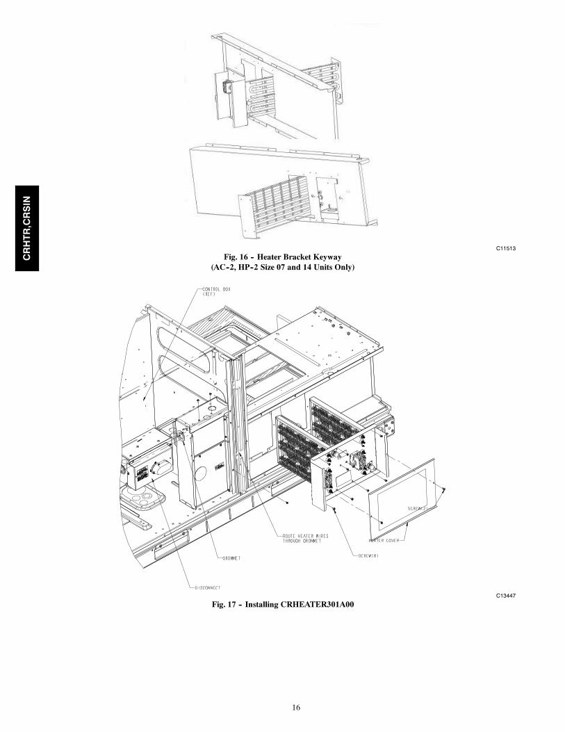
b. Heater CRHEATER301A00 only: To installmodule, insert both heater frames into locationnotches in heater bracket opening in unit andslide heater through the opening. Fasten heatermodule to heater mounting bracket with the 4screws saved from Step 1. (See Fig. 17.)
c. All other heaters: To install module, engageflange on heater with track in unit and slideheater through mounting bracket opening. Fastenheater module to heater mounting bracket withthe 4 screws saved from Step 1. (See Fig. 15.)
5. Single----phase heater conversion208/230----v heaters CRHEATER101A00 through104B00 are factory----wired for 3----phase applica-tions but can be converted to single----phase bychanging one wire as described below.
Three----phase applications: Skip to Step 6.
For single----phase applications, rewire the heater asfollows (see Fig. 11):a. Connect 10----gauge RED wire provided withheater package to splice connector included inpackage.
b. Remove YEL wire from heater relay HR at ter-minal 11.
c. Reconnect the YEL wire from step b to spliceconnector on RED wire.
d. Using the wire tie provided, fasten RED wire toheater power wire harness near existing wire tieon heater module. This provides strain relief forthe red wire. See Fig. 12.
Connect the BLU and YEL conductors in theheater power wire harness to same L1 pole onsingle point box TB or FU fuse block. Connectthe BLK and RED conductors in the heater pow-er wire harness to same L2 pole on single pointbox TB or FU fuse block. See Fig. 11 .
LEGENDHR -- Heater RelayHTR -- HeaterLS -- Limit Switch
CONNECTTO L2
CONNECTTO L1
Connect YELat splice
DisconnectYEL
C13448
Fig. 11 -- Single--Phase Heater Wiring
MODEL NO.
ERIAL NO.
1113
2123
OD
22.2
3123
ISTED AIRNDITIONINGUIP ACCESS 346N.
P / N 2- 5610-4 REV
RED WIRE
SPLICECONNECTOR
HEATERPOWERWIREHARNESS
Wire Tie
C13449
Fig. 12 -- Typical Single--Phase Wiring Installed
CRHTR,CRSIN

15
6. Route power wires from heater module(s) throughthe foam bushing in the center partition and into thesingle point box. (See Fig. 3.) Connect to terminalblock or fuse blocks per schematics in Appendix Aor B. See Tables at beginning of each Appendix toidentify the appropriate figure.
All heaters are single bank heaters exceptCRHEATER111A00, 112A00, 268A00, 269A00,301A00, 318A00 and 321A00 which are dual bankheaters. These heaters will be wired as two heaters(i.e., 6 leads). Fusing is shown pictorially on theunit wiring schematic label.
If no single point box is required for the unit andheater combination, run the heater power supplywiring through the grommet holes to the main unitcontrol box’s field power connection points or tooptional factory--supplied disconnect.
7. Factory control wiring for heaters runs from unitcontrol box to terminal block TB--4, mounted in theheater compartment above module 1 location. (SeeFig. 6 and 18.) Connect the heater control wiring atTB--4.
CONDUIT CONDUITDRIP BOOT
WIRE TIE
C—
CO
MM
30V—
OR
200V—
RD
OV
—Y
LD
24V 75VA
BD
236BN
—T
RA
N 3O
—B
V2075
E 60 H
Z 30-8703
C08417
Fig. 13 -- Typical Conduit Installation
KEY FOR MODULE LOCATON 1
C09010
Fig. 14 -- Typical Electric Heat Installation(AC--1 Sizes 04 to 07 and 036 to 072, AC--2 Sizes 04--06,HP--1 Sizes 04--07 and 036 to 072, HP--2 Sizes 04--06)
TRACK
FLANGE
HEATERSLIDE
TRACK SCREWS
KEY FOR MODULE LOCATION 1
C10557
Fig. 15 -- Typical Module Installation(AC--1 Sizes 08 to 14 and 090 to 150, AC--2 Sizes 07--12,HP--1 Sizes 08--12 and 090 to 121, HP--2 Sizes 07--09)
CRHTR,CRSIN
16
C11513
Fig. 16 -- Heater Bracket Keyway(AC--2, HP--2 Size 07 and 14 Units Only)
C13447
Fig. 17 -- Installing CRHEATER301A00
CRHTR,CRSIN

17
LCTB
CONTLBOARD
ORN
BRN
FieldConnections
HR1: On Heater 1 in Position #1HR2: On Heater 2 in Position #2 (if installed)
2
3
12
1 3
VIO
ORN VIO BRN
VIO BRN BRNVIO
2TB4
VIO HR2
HR1
BRN
VIO BRN
Elec Htr
C08331
Fig. 18 -- Accessory Electric Heater ControlConnections (AC--1 Except Size 16 and 180,
AC--2 Except Size 14 and 150)
C11555
Fig. 19 -- Accessory Electric Heater Control Connections(AC--2, Size 06 and 060, 575V only)
DEFROSTBOARD
ORN
BRN
FieldConnections
E-HEAT
P3-3
1 3
ORN BRN
VIO BRN BRNVIO
TB4
VIO HR2
HR1
BRN
VIO BRN
Elec Htr
HR1: On Heater 1 in Position #1HR2: On Heater 2 in Position #2 (if installed)
C09013
Fig. 20 -- Accessory Electric Heater ControlConnections (HP--1 Except Size 14 and 150,
HP--2 Except Size 12 and 120)
C11554
Fig. 21 -- Accessory Electric Heater Control Connections(HP--2, Size 06 and 060, 575V only)
CRHTR,CRSIN

18
MODEL NO.
ERIAL NO.
1113
2123
OD
3123
ISTED AIRNDITIONINGUIP ACCESS 346N.
P / N 2- 5610-4 REV
C08137
Fig. 22 -- Typical 3--Phase Wiring Installed
INSTALLATION INSTRUCTIONS,SECTION 2
Product Groups/Sizes included in this section:AC--1 16 (180)AC--2 14 (150)AC--3 08--12HP--1 14 (150)HP--2 12 (120)
Check sales packages – Following the project drawingschedule tables or submittal documents, select thescheduled heaters and single point boxes (if used) andplace at each unit.Compare the sales package number(s) for scheduledheater modules against the approved usage table on theunit’s infoplate. See Fig. 1 and 2 for typical plate data. Ifthe scheduled heater usage does not appear on the unitinfoplate label, STOP. Contact the project engineer or thelocal distributor sales office for clarification.Open the cartons and inspect for damage.
Disconnect field power supply1. Disconnect power to the unit. Lock----out/tag----outon unit disconnect switch.
2. Open and remove the access panel and cover to themain control box.
3. Use a voltmeter to check that no power is present atunit terminal block.
Install Single Point Box (CRSINGLE047A00,050A00----054A00)
1. Remove kits from boxes and verify that all of thecorrect parts have arrived undamaged.
2. If power is already connected to unit, disconnect allpower to the unit per correct lock----out/tag----outprocedures.Disconnect field power wiring or optional factory--
installed disconnect or HACR power leads at TB1and withdraw the wiring from the unit control box.
3. Remove outdoor access, control box, and left indooraccess panels from the unit. See Fig. 23. Fig. 24shows the unit with the panels already removed.
4. Optional – The center post may be removed to facil-itate wiring.
5. Remove the bushings and plug from the controlpanel per Fig. 25. Save the bushings and discard theplug.
6. Add seal strip to the rear bottom corner of the con-trol panel as shown in Fig. 26.
7. Foil tape open screw holes on the back of the singlepoint box as shown in Fig. 26. Different single pointboxes will have different screw holes open.
HEATERCOVERS
HEATERMOUNTINGBRACKETHEATER
MODULE(LOCATION 2)
HEATERMODULE(LOCATION 1)
MAINCONTROLBOX
SINGLE POINT BOX(NOT SHIPPED WITHUNIT)
CENTERPOST
C11515
(AC--1 16/180, AC--2 14--150, AC--3 08--12, HP1 14/150, HP--212/120)
Fig. 23 -- Typical component Location
CRHTR,CRSIN

19
Control BoxAccessPanel
OutdoorAccessPanel
Heater Covers
LeftIndoorAccessPanel
C10170
Fig. 24 -- Typical Unit with Access Panels Removed
Single Point Box Mounting Screws
Plug Location
Bushings(Re-installed)
C10169
Fig. 25 -- Single Point Box Installation Details
CRHTR,CRSIN

20
Seal Bottom Corner
Seal Back Corner
Foil Tape LocationsC101085
Fig. 26 -- Seal Strip and Foil Tape Locations
8. Remove the cover from the single point box.9. Install the single point box under the control panelwith two screws down through the control panel(Fig. 25) and one screw (not shown) into the centerpost. (See Fig. 25.) Holes have been provided.Foam wire guides in the center post may have to beremoved. If center post was removed per step 4, thesingle point box will have to be screwed into itlater.
10. The single point box kit will contain two rain shieldbrackets, a larger bracket with boot seal and a smal-ler (shorter) bracket without a seal. Remove theseal from the larger bracket and push the conduitdrip boot seal into the short rain shield bracket. (SeeFig. 27.) Discard the larger bracket.
Conduit Drip Boot
Rain Shield BracketC10167
Fig. 27 -- Rain Shield Installation
11. Install the rain shield bracket to the left and behindthe single point box using the two screws and holesprovided.
12. Re--install the bushings removed in Step 5.13. Connect the tap conductors.
a. CRSINGLE047A00, 050A00 and 052A00Connect the blue, yellow, and black power tap
conductors (pigtails) from the single point box tothe unit’s power terminal block TB--1 per unitlabel wiring schematic and per Appendix A or Band connection figures. A representative installa-tion of two 480V heaters and correspondingsingle point box is shown in Fig. 28, 29, and 30.
b. CRSINGLE051A00, 053A00 and 054A00These kits include two sets of tap conductors(blue, yellow and black pigtails) connected atfuse blocks 1 and 2. Connect these leads in par-allel to the unit’s power terminal block TB--1 perthe unit label wiring schematic and per Ap-pendix A, B or C and connection figures.(These kits also include two small terminalblocks (TB10). The TB10 blocks are not usedwith large cabinet units in this section; discard.)
Install CRHEATER288A00--296A001. Remove and save the heater covers.2. Install heater slide track(s) from the heater kitthrough the bottom of the heater mounting hole(s)and fasten each with the two screws provided. (SeeFig. 31.)
3. Install the heater(s) (Fig. 32, 230V shown) into theirmounting location(s) using the screws provided.Tables 2 and 3 give the correct heater location as afunction of heater size, voltage, and supply air flowdirection and unit supply air opening size
NOTE 1: Heaters with Restrictor PlatesHeater part numbers CRHEATER288A00, 289A00,290A00, 294A00, 295A00 and 296A00 have a RestrictorPlate attached to the heater base plate (see Fig. 33). Thehorizontal projection of this plate engages a slot on thelower left--hand side of Heater Position 2 (right--handopening), thus permitting a heater mounting in theright--hand heater opening and preventing its inadvertentmounting in the left--hand heater opening.On certain heater applications in Tables 2 and 3,designated by dagger ({) symbol, a heater with aRestrictor Plate must be installed in the left--hand heateropening. On these installations ONLY, remove the twoscrews at the Restrictor Plate, remove the plate anddiscard the plate and screws. Apply foil tape over theopen screw holes.NOTE 2: Heater CRHEATER295A00, Vertical Unit,Table 3.The mounting location for heater CRHEATER295A00differs based on unit type. When this heater is installed ina unit type AC--1, AC--2 or AC--3 with vertical supplyduct (unit base opening size is approximately 36 x 28inches), the heater is located in Heater Position 2(right--hand opening), with Restrictor Plate intact.When this heater is installed in a unit type HP--1 or HP--2with vertical supply duct (unit base opening size isapproximately 30 x 16 inches), the heater is located inHeater Position 1 (left--hand opening) and Restrictor Platemust be removed. On these installations ONLY, removethe two screws at the Restrictor Plate, remove the plateand discard the plate and screws. Apply foil tape over theopen screw holes.
CRHTR,CRSIN

21
C10174
Fig. 28 -- Heater Wiring
C10172
Fig. 29 -- Typical Single Point Box Wiring
CRHTR,CRSIN

22
Single Point BoxPower Wires
C10175
Fig. 30 -- Typical Control Panel Wiring
Mounting ScrewsHeater Slide Track
C10198
Fig. 31 -- Heater Slide Track Installation
CRHTR,CRSIN

23
Dual ElementHeater Module
Heater Mount Locations
Single ElementHeater Module
C10168
Fig. 32 -- Typical Heaters
Table 2 – Heater Location for HorizontalReturn and Discharge*
HeaterkW Volts
Heater Slot Location
CRHEATERXXXX00 Left Right
288A 10.0 240 -- 288A
291A 16.5 240 291A --
288A + 291A 26.5 240 291A 288A
294A 33.5 240 -- 294A
288A + 294A 43.5 240 288A{ 294A
291A + 294A 50.0 240 291A 294A
294A + 294A 67.0 240 294A{ 294A
289A 10.0 480 -- 289A
292A 16.5 480 292A --
289A + 292A 26.5 480 292A 289A
295A 33.5 480 -- 295A
289A + 295A 43.5 480 289A{ 295A
292A + 295A 50.0 480 292A 295A
295A + 295A 67.0 480 295A{ 295A
290A 10.0 600 -- 290A
293A 16.5 600 293A --
290A + 293A 26.5 600 293A 290A
296A 33.5 600 -- 296A
290A + 296A 43.5 600 290A{ 296A
293A + 296A 50.0 600 293A 296A
296A + 296A 67.0 600 296A{ 296A* XXXX --- 4 digit heater in table. For example, a CRHEATER291A000 islisted as a 291A.{Remove Restrictor Plate to install in Left Slot Location. Use foil tape tocover holes.
Table 3 – Heater Location for VerticalReturn and Discharge*
HeaterkW Volts
Heater Slot Location
CRHEATERXXXX00 Left Right
288A 10.0 240 -- 288A
291A 16.5 240 291A --
288A + 291A 26.5 240 291A 288A
294A 33.5 240 -- 294A
288A + 294A 43.5 240 288A{ 294A
291A + 294A 50.0 240 291A 294A
294A + 294A 67.0 240 294A{ 294A
289A 10.0 480 -- 289A
292A 16.5 480 292A --
289A + 292A 26.5 480 292A 289A
295A(See Note 2, Page20)
33.5 480295A {(HP---1
HP---2 only)
295A(AC---1,AC---2,
AC---3 only)
289A + 295A 43.5 480 289A{ 295A
292A + 295A 50.0 480 292A 295A
295A + 295A 67.0 480 295A{ 295A
290A 10.0 600 -- 290A
293A 16.5 600 293A --
290A + 293A 26.5 600 293A 290A
296A 33.5 600 -- 296A
290A + 296A 43.5 600 290A{ 296A
293A + 296A 50.0 600 293A 296A
296A + 296A 67.0 600 296A{ 296A* XXXX --- 4 digit heater in table. For example, a CRHEATER291A000 islisted as a 291A.{ Remove Restrictor Plate to install in Left Slot Location. Use foil tape tocover holes.
CRHTR,CRSIN

24
C13466
Fig. 33 -- Restrictor Plate
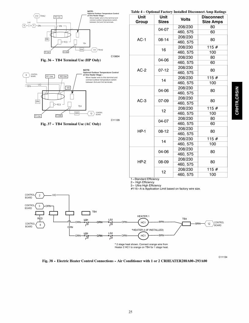
4. Connect the heater control wiring to terminal blockTB4 (located to left of the heaters, see Fig. 43 and44.)TB4 has five terminals. (See Fig. 34 and 36.) Bot-tom row left terminal is “R Use”; it has a factoryRED connection. Bottom row right terminal is “CUse”; it has a factory BRN connection. For ACunits, top row left is designated as “W1 Use” ad hasfactory ORN connections. The top row center isdesignated as “W2 Use” and has factory VIO con-nections. For HP units, top row left and center ter-minals are designated “W2 Use” and have factoryORN connections. The fifth terminal is for field--option connection of a staging control.
CRHEATER288A00--293A00 HeatersThese heaters have two control wires: ORN forheater contactor and BRN for control common.Connect BRN wire(s) to TB4’s “C Use” terminal.(Second BRN wire will require use of the piggybackterminal on the factory BRN wire.) For AC units,connect heater ORN control wiring to ORN on TB4for 1st stage heating and for units with heater pack-ages, connect to VIO on TB4 for 2nd stage heating.(See Fig. 38.) For HP units, connect heater ORNcontrol wires(s) to an available terminal on TB4’s“W2 Use” group. (See Fig. 40.)
CRHEATER294A00--296A00 HeatersThese heaters have four control wires: ORN andVIO for heater contactors, RED for safety circuitpower and BRN for control common. Connect REDwire to TB4’s “R Use”. Connect BRN wire toTB4’s “C Use” terminal. For AC units with oneheater package that has these 4 control wires, con-nect heater ORN control wiring to ORN on TB4 for1st stage heating and to VIO on TB4 for 2nd stageheating.For AC units with 2 of these heater packages that
has 4 control wires, connect both the ORN and VIOcontrol wires from the heater to ORN on TB4 for 1st
stage heating and connect the ORN and VIO controlwires from the other heater to VIO on TB4 for 2nd
stage heating. (See Fig. 39.)For AC units with one of these heater packages thathas these 4 control wires plus a heater package thathas 3 control wires, connect both the ORN and VIOcontrol wires from the 4 control wire heater to ORNon TB4 for 1st stage heating and connect the ORNcontrol wire from the other heater with 3 controlwires to VIO on TB4 for 2nd stage heating.For HP units, connect ORN and VIO wires to TB4’s“W2 Use” terminals.(See Fig. 42.)
NOTE 4AND 6
RED
EHR
EHRORN
TRAN2 FROM POWER SCHEMATIC
24V BRN24V
CB
3.2 AMPS
BRN
GRN/YEL
24V
RED
BRN
1 0
1 0
8 6
FPT
BLK BLK
BRNBRN
BRN
RED
ELECTRICHEAT(ACCESSORY)SEE HEATER LABEL DIAGRAM
BRN
BRN
24V
5
TRAN1 FROM POWER SCHEMATIC
24V BRN24VGRN/YEL
CB
3.2 AMPS
BRNOFRVIO
TB4
3
ORN ORN
RED
C10561
Fig. 34 -- TB4 Wiring (HP Only)
C11127
Fig. 35 -- TB4 Wiring (AC Only)
CRHTR,CRSIN
25
NOTE:Optional Outdoor Temperature Controlat One Heater Stage – Move heater wire to this terminal and connect outdoor temperature switch between 2nd and 3rd terminals.
W2 Use
R Use C Use
C10604
Fig. 36 -- TB4 Terminal Use (HP Only)
NOTE:Optional Outdoor Temperature Controlat One Heater Stage – Move heater wire to this terminal and connect outdoor temperature switch between 2nd and 3rd terminals.
W1 Use
R Use C Use12 CONTROL
BOARD
8 CONTROLBOARD
VIOVIO
W2 Use
C11129
Fig. 37 -- TB4 Terminal Use (AC Only)
Table 4 – Optional Factory Installed Disconnect Amp Ratings
UnitGroup
UnitSizes Volts Disconnect
Size Amps
AC-1
04-07208/230 80460, 575 60
08-14208/230
80460, 575
16208/230 115 #460, 575 100
AC-2
04-06208/230 80460, 575 60
07-12208/230
80460, 575
14208/230 115 #460, 575 100
AC-3
04-06208/230
80460, 575
07-09208/230
80460, 575
12208/230 115 #460, 575 100
HP-1
04-07208/230 80460, 575 60
08-12208/230
80460, 575
14208/230 115 #460, 575 100
HP-2
04-06208/230
80460, 575
08-09208/230
80460, 575
12208/230 115 #460, 575 100
1---Standard Efficiency2--- High Efficiency3--- Ultra High Efficiency#115---A is Application Limit based on factory wire size.
HC1
HC1
HEATER 1
*HEATER 2 (IF INSTALLED)
BRN
BRN
BRN
TB4
TB4
ORN
ORN
RED
8 12CONTROLBOARD
U
VIO
CONTROLBOARD
CONTROLBOARD
3
CONTROLBOARD
2
* 2 stage heat shown. Connect orange wire fromHeater 2 HC1 to orange on TB4 for 1 stage heat.
LS1ORN
LS1 LS2ORNORN ORN
LS1ORN
LS1 LS2ORNORN ORN
C11134
Fig. 38 -- Electric Heater Control Connections -- Air Conditioner with 1 or 2 CRHEATER288A00--293A00
CRHTR,CRSIN

26
HC2
HC1
HCR2
HCR1 BRN
BRN
BRN
BRN
BRN BRN
HCR1
HCR2
RED
ORN
VIO
ORN
TB4
TB4
12 CONTROLBOARD
U
8
CONTROLBOARD
CONTROLBOARD
3
CONTROLBOARD
12 VIO
RED
REDLS1LS1 LS2
RED
C11135
Fig. 39 -- Electric Heater Control Connections -- Air Conditioner with 1 CRHEATER294A00--296A00
TRAN2
HC1
HC1
HEATER 1
HEATER 2 (IF INSTALLED)
BRN
BRN
BRN
TB4TS
TS
TB4
ORN
ORN
RED ORN
ORNEHR
TB4
RED
C13468
Fig. 40 -- Electric Heater Control Connections--Heat Pump with 1 or 2 CRHEATER288A00--293A00
TRAN2
HC2
HC1
HCR2
HCR1 BRN
BRN
BRN
BRN
BRN BRN
BRN
HCR1
HCR2
RED
RED
TB4
RED ORN
ORNEHR
VIO
ORN
TB4
RED
TB4
LS1LS1 LS2RED
C13469
Fig. 41 -- Electric Heater Control Connections--Heat Pump with 1 CRHEATER294A00--296A00
CRHTR,CRSIN

27
TRAN2
HC2
HC1
HC1
HCR2
HCR1
BRN
BRN
BRN
BRN
BRN
BRN BRN
TB4
HCR2
HCR1RED
RED
TB4
RED ORN
EHRORN
ORN
VIO ORN
TB4
LS
1-STG HEATER
2-STG HEATER
BRNRED
LS1LS1 LS2RED
2-Stage Heater
C13470
Fig. 42 -- Electric Heater Control Connections--Heat Pump with 1 CRHEATER288A00--293A00Plus 1 CRHEATER294A00--296A00 (2--Stage Heater)
Terminal Block 4(TB4)
Heater Cover
C10173
Fig. 43 -- Heater Wiring
CRHTR,CRSIN

28
Terminal Block 4(TB4)
Heater Covers
C10171
Fig. 44 -- Heater Wiring and Covers
C11512
Fig. 45 -- Max. Air Temp/Max. Ext. Static
CRHTR,CRSIN

29
UNIT POWER SUPPLY WIRING –ALL UNITS
NOTE: Installers of unit power supply wiring connectingto these air conditioning and heat pump units must befamiliar with applicable requirements of the NationalElectrical Code (NFPA Standard 70), Articles 440, 430and 424 dealing with multiple load systems incorporatingrefrigeration compressors, motors and electric heatingequipment. Installers must also be familiar with andobserve all local codes regarding unit power supplywiring.
In most instances, adding electric heaters to these unitswill result in an increase in unit power supply wire sizecompared to base unit electrical loads. These changes mayalso impact the size selection of the branch circuitoverload protection device and the unit safety disconnectswitch. Check the unit’s informative data label (see Fig.1 and 2 for examples) for minimum wiring sizingampacity for full combined load (including power exhaustif also installed), for branch circuit protection size (amaximum value) and for unit minimum disconnect switchsize.
Device Infoplate DesignationPower Supply Wire MIN CKT AMPSBranch Circuit Protec-tion
FUSE OR HACRBREAKER
Disconnect Switch MINIMUM UNIT DIS-CONNECT
All wiring that terminates at a unit-mounted terminal mustbe selected from wiring materials under the NEC Table310.15(B)(16), 75 C (or higher) column only. Checkspecifications for external disconnect lug sizes todetermine if 60 C wiring materials may be used betweenbranch circuit origin and the disconnect switch.There are four different situations that an installer canencounter with these units. Three are for new unitinstallations (base unit has not been connected to a powersupply already): Unit without factory disconnect switch,unit with factory disconnect switch and unit with factoryHACR breaker. The fourth situation is for an existing unitalready connected to a power supply and the heaters arebeing retrofitted. For each situation, there is usually awithout single point box and a with single point boxcondition. Each situation is discussed below.
New Unit Without Factory Disconnect or HACRInstallation WITHOUT Single Point Box: Unit powersupply wires from the external (field-supplied) disconnectswitch are connected to the base unit’s power connectionterminal lugs. Refer to unit wiring label to identify theseterminals (these may be lugs on contactors or at powerterminal block). The heater power wires are alsoconnected at these terminals.Installation WITH Single Point Box:Remove knockouts for appropriate size conduitfrom unit block----off panel and single point box. Installconduit (rigid or electrometallic tubing)through conduit drip boot as shown. (See Fig. 13.)
Drip boot will accept conduit sizes 3/4----in. to 1----1/2inches. The drip boot eliminates the need for watertightconduit fittings at the single point box.Unit power supply wires from the external (field-supplied)disconnect switch are connected to the power lugs on thefield connection device provided in the Single Point Box.This device may be a terminal block or fuse block FU2’sline side terminals. The heater power wires are connectedto the load side terminals on the same device.
New Unit With Factory DisconnectThe optional factory----supplied disconnect has amaximum rating per Table 4.Check this unit’s infodata plate for the MINIMUMDISCONNECT SWITCH value (see Fig. 1 and 2) andcompare to the Table 4 value.If required minimum disconnect value is LOWER thanrating in Table 4: Reconnect the factory wiring from thefactory disconnect at the Single Point Box’s terminalblock or fuse block FU2’s line side terminals (or to maincontrol box’s line connection lugs if no Single Point Boxis installed). Remove any factory test leads connected atdisconnect line side terminals; discard these wires.Connect unit power supply wires to disconnect switch lineside lugs.If required minimum disconnect value is HIGHER thanrating in Table 4:For unit with 60--A, 80--A or 100--A disconnect, removethe factory disconnect switch assembly and wiring. Installa field--supplied disconnect switch sized per unit marking.Complete connections per instructions above under “NewUnit Without Factory Disconnect or HACR.”For unit with 115--A disconnect AND required minimumdisconnect value per unit infodata plate is less than200--A: Remove the factory wires at load side terminalsof the disconnect switch. Size new wires based on unitMIN CKT AMPS value for unit plus heaters plus powerexhaust (if installed). Connect new wires at disconnectswitch load side terminals and to Single Point Box’sterminal block or fuse block FU2’s line side terminals.Remove any factory test leads connected at disconnectline side terminals; discard these wires. Connect unitpower supply wires to disconnect switch line side lugs.For unit with 115--A disconnect AND required minimumdisconnect value per unit infodata plate is GREATER than200--A: Remove the factory disconnect switch assemblyand wiring. Install a field--supplied disconnect switchsized per unit marking. Complete connections perinstructions above under “New Unit Without FactoryDisconnect or HACR.”
New Unit With Factory HACRThe amp rating of the HACR factory installed option isbased on the size, voltage, indoor motor and otherelectrical options of the unit as shipped from the factory.When field installed accessory electric heaters are addedto the unit, the HACR may no longer be of the proper amprating and therefore will need to be removed from theunit.Check this unit’s infodata plate for the FUSE OR HACRBREAKER value (see Fig. 1 and 2) and compare to thefactory HACR breaker rating value.
CRHTR,CRSIN

30
If marked HACR value on unit dataplate isUNCHANGED from rating unit--mounted HACR:Reconnect the factory wiring from the factory HACR atthe Single Point Box’s terminal block or fuse block FU2’sline side terminals (or to main control box’s lineconnection lugs if no Single Point Box is installed).Remove any factory test leads connected at HACR lineside terminals; discard these wires. Connect unit powersupply wires to HACR line side lugs.If marked HACR value on unit dataplate is GREATERthan rating on unit--mounted HACR: Remove the factoryHACR switch assembly and wiring. Install afield--supplied fused or HACR disconnect switch sized perunit marking. Complete connections per instructionsabove under “New Unit Without Factory Disconnect orHACR.”
Existing UnitAn existing unit will usually have been installed followingthe values marked on the base unit’s informative dataplate for wire sizing, branch circuit over-currentprotection and disconnect switch rating. When electricheaters are added to air conditioning (cooling) units, thesevalues may be changed; when electric heaters are added toheat pump units, one or more of these values will bechanged.Check the installed unit’s field power wires for conductorsize and determine conductor rated ampacity per NECTable 310.15(B)(16). Compare this value to the MINCKT AMPS value on the unit infoplate for base unit pluselectric heaters (plus power exhaust if connected). If theMIN CKT AMPS value is greater than the rated ampacityof the power supply wires, the unit power supplyconductors must be replaced.NOTE: Supply wiring must comply with NEC (National
Electrical Code) and all local requirements.Check the installed unit’s branch circuit over-currentprotection device (fuse or HACR breaker) for rating inamps. Compare this value to the FUSE OR HACRBREAKER value on the unit infoplate for base unit pluselectric heaters (plus power exhaust if connected). If theFUSE OR HACR BREAKER value is greater than therated ampacity of the installed device, the unit branchcircuit over-current protection device must be replaced.Check the installed unit’s disconnect switch for rating inamps. Compare this value to MINIMUM UNITDISCONNECT value on the unit infoplate for base unitplus electric heaters (plus power exhaust if connected). Ifthe MINIMUM UNIT DISCONNECT value is greaterthan the rated ampacity of the installed disconnect switch,the unit disconnect switch must be replaced.To complete the unit power wiring at the Single Point Boxor base unit terminals, follow the appropriate directionsunder ”New Unit” discussions above.
Complete Unit Installation1. Mark the appropriate block on the unit nameplatefor the accessory heater kW installed. Note the re-quired MIN CKT AMPS value for this unit----heatercombination. Ensure the field power conductors aresized to handle this ampacity.
2. Locate the heater covers. For all heaters exceptCRHEATER301A00, the heater cover is the plateremoved from the heater mounting bracket in Step 4page 11 or Step 3 page 18. For CRHEATER301A00only, a new, wider cover is included in the accessoryheater package. See Fig. 17.
3. Place adhesive----backed wiring label on flangedside of heater cover.
4. Fasten heater cover to heater module with 2 screwsprovided with heater. Flanges of cover must faceout. (See Fig. 44)
5. Set manual reset limit switch (on supply fan hous-ing) by depressing button located between the ter-minals on the switch. (See Fig. 3.)
6. Close single point box cover and secure with onescrew.
7. Replace control box cover, using remainder ofscrews saved from page 11, Step 4 or page 18, Step3 of Installing Single Point Box sections.
8. Run conduit through (rigid or EMT) the conduitdrip boot in the rain shield bracket to the singlepoint box. Provide an appropriate fitting to connectthe conduit to the single point box wall and groundappropriately. (See Fig. 28.) Drip boot eliminatesthe need for watertight conduit fittings at the singlepoint box.
9. Run wire through conduit connecting outside powerto the designated terminals at the top of the singlepoint box. Ground appropriately. (See Fig. 30.)
10. Replace indoor and outdoor panels with screwssaved from Step 2 of Installing Single Point Boxsection on page 8. Place adhesive----backed Max.Air/ Max. Static label on external panel that coversheaters. (See Fig. 4, 5, and 45.)
11. If all other work on the unit is done, reapply unitpower per lock----out/tag out procedures.
CRHTR,CRSIN
31
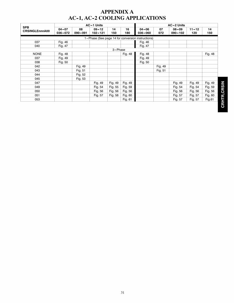
APPENDIX AAC--1, AC--2 COOLING APPLICATIONS
SPBCRSINGLEnnnA00
AC---1 Units AC---2 Units04---07036---072
08090---091
09---12102---121
14150
16180
04---06036---060
07072
08---09090---102
11---12120
14150
1---Phase (See page 14 for conversion instructions)037 Fig. 46 Fig. 46040 Fig. 47 Fig. 47
3---PhaseNONE Fig. 48 Fig. 48 Fig. 48 Fig. 48037 Fig. 49 Fig. 49038 Fig. 50 Fig. 50042 Fig. 49 Fig. 49043 Fig. 51 Fig. 51044 Fig. 52045 Fig. 53047 Fig. 49 Fig. 49 Fig. 49 Fig. 49 Fig. 49 Fig. 49049 Fig. 54 Fig. 55 Fig. 59 Fig. 54 Fig. 54 Fig. 59050 Fig. 56 Fig. 56 Fig. 56 Fig. 56 Fig. 56 Fig. 56051 Fig. 57 Fig. 58 Fig. 60 Fig. 57 Fig. 57 Fig. 60053 Fig. 61 Fig. 57 Fig. 57 Fig.61
CRHTR,CRSIN

32
Unit Control BoxC IFC
13 13 11
HEATER
HeaterWires
Unit DisconnectMOCP 60-A Max
FieldPowerConductors
C13477
Fig. 46 -- AC 1--Phase Single Point Box CRSINGLE037A00
Unit Control BoxC
11 11
FU2
HTR 1
FU3
HTR 2
HeaterFactory wiring connects line-side Wiresof FU2 to line-side terminals on FU3.
11 23
BLK + RED
BLU + YEL
BLK + RED
BLU + YEL
YELTapConductors
FieldPowerConductors
BLK
C13478
Fig. 47 -- AC 1--Phase Single Point Box CRSINGLE040A00
CRHTR,CRSIN

33
Unit Control Box
AC-1 SIZE 16 (180) BLK BLUYELAC-1 SIZE 16 (180)AC-2 SIZE 14 (150)HP-1 SIZE 14 (150)HP-2 SIZE 12 (120) 11 12 13TB-1
ULBKLB YEL
BLUUnit Control Box
C IFC
AC-1, AC-2HP-1, HP-2ALL EXCEPT ABOVE
WITH VFD
WITHOUT
IFTB
BLU
11 1111 13 11
BLK BLUYEL
VFD13
FieldPowerConductors
HEATER
BLK BLUYEL
Unit DisconnectMOCP 60-A Max
HeaterWires
C13479
Fig. 48 -- AC, HP — No Single Point Box
CRHTR,CRSIN

34
Unit Control Box
AC-1 SIZE 16 (180)AC-2 SIZE 14 (150)HP-1 SIZE 14 (150) 11 12 13TB-1
ULBKLB YEL
Unit Control Box
AC-2 SIZE 14 (150)HP-1 SIZE 14 (150)HP-2 SIZE 12 (120) 11 12 13TB-1
BLK BLUYEL
IFTB
BLU
C IFC
11 1111 13 11
AC-1, AC-2HP-1, HP-2ALL EXCEPT ABOVE
WITH VFD
WITHOUTVFD13
IFTB
TapConductors
FieldPower
TB
HEATER
ConductorsConductors
Unit DisconnectMOCP 60-A Max
HeaterWires
SPB037A042A047A
C13480
Fig. 49 -- AC Single Point Box CRSINGLE037A00, 042A00, and 047A00
CRHTR,CRSIN

35
Unit Control BoxC IFC
FU2HEATER
FU3HEATER
!!"5"5
HeaterWires
Factory wiring connects line-sideof FU2 to line-side terminals on FU3.This wiring not illustrated for simplicity in this figure.
FieldPower Conductors
Tap Conductors
13 13 11
Field TapPower Conductors
Heater 104 #2if used
Heater 104 #1or Heater 105
C10486
Fig. 50 -- AC Single Point Box CRSINGLE038A00
Unit Control BoxC
11 13 11 13
IFCTB-10BTB-10A
FU2HEATER111A or 112A
CIR 1
CIR 2
BLU BLUBLK BLKYEL YEL
HEATERWIRES
TAPCONDUCTORS
FIELDPOWER
CONDUCTOR
ALT.TWO HEATER
MODULESFactory wiring connects line-sideof FU2 to line-side terminals on FU3.This wiring not illustrated for simplicity in this figure.
FU3
C10489
Fig. 51 -- AC Single Point Box CRSINGLE043A00
CRHTR,CRSIN

36
Unit Control BoxC IFC
TB
FU2HEATER
FU3HEATER
Factory wiring connects line-sideof FU2 to line-side terminals on FU3.This wiring not illustrated for simplicity in this figure.
11
TapConductors
FieldPowerConductors
HeaterWires
13 13
C10490
Fig. 52 -- AC Single Point Box CRSINGLE044A00
Factory wiring connects line-sideof FU2 to line-side terminals on FU3-FU4.This wiring not illustrated for simplicity in this figure.
Unit Control Box C IFC
FU2HEATER111A or 112A
CIR 1
CIR 2
HEATER
11 13 11 13
HEATERWIRES
TAPCONDUCTORS
FIELDPOWER
CONDUCTOR
BLU BLUBLK BLKYEL YEL
TB-10BTB-10A
FU3
FU4
C10491
Fig. 53 -- AC Single Point Box CRSINGLE045A00
CRHTR,CRSIN

37
Unit Control BoxC
11 13 11 13
IFCTB-10BTB-10A
FU2HEATER111A or 112A
CIR 1
CIR 2
BLU BLUBLK BLKYEL YEL
HEATERWIRES
TAPCONDUCTORS
FIELDPOWER
CONDUCTOR
ALT.TWO HEATER
MODULESFactory wiring connects line-sideof FU2 to line-side terminals on FU3.This wiring not illustrated for simplicity in this figure.
FU3
C10489
Fig. 54 -- AC Single Point Box CRSINGLE049A00(Except Size 14--16 and 150--180)
Unit Control BoxC2 TB-10 C1 IFC
FU2HEATER112A
CIR 1
HEATER117A or 110A
CIR 2
$$&:&:
11 13 11 13 13
HEATERWIRES
TAPCONDUCTORS
FIELDPOWER
CONDUCTOR
Factory wiring connects line-sideof FU2 to line-side terminals on FU3.This wiring not illustrated for simplicity in this figure.
BLU BLUBLK BLKYEL YEL
FU3
C10566
Fig. 55 -- AC Single Point Box CRSINGLE049A00(AC Sizes 14 and 150 Only)
CRHTR,CRSIN

38
Unit Control BoxC IFC
TB
FU2HEATER
FU3HEATER
Factory wiring connects line-sideof FU2 to line-side terminals on FU3.This wiring not illustrated for simplicity in this figure.
11
TapConductors
FieldPowerConductors
HeaterWires
13 13
C10490
Fig. 56 -- AC Single Point Box CRSINGLE050A00
Factory wiring connects line-sideof FU2 to line-side terminals on FU3-FU4.This wiring not illustrated for simplicity in this figure.
Unit Control Box C IFC
FU2HEATER111A or 112A
CIR 1
CIR 2
HEATER
11 13 11 13
HEATERWIRES
TAPCONDUCTORS
FIELDPOWER
CONDUCTOR
BLU BLUBLK BLKYEL YEL
TB-10BTB-10A
FU3
FU4
C10491
Fig. 57 -- AC Single Point Box CRSINGLE051A00(AC--1 Except Size 14--16 and 150--180)
CRHTR,CRSIN
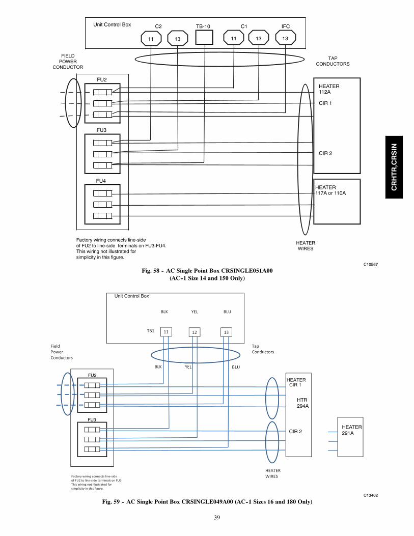
39
Unit Control Box C2 C1 TB-10 IFC
FU2HEATER112A
CIR 1
CIR 2
HEATER117A or 110A
HEATERWIRES
TAPCONDUCTORS
FIELDPOWER
CONDUCTOR
Factory wiring connects line-sideof FU2 to line-side terminals on FU3-FU4.This wiring not illustrated for simplicity in this figure.
11 13 11 13 13
FU3
FU4
C10567
Fig. 58 -- AC Single Point Box CRSINGLE051A00(AC--1 Size 14 and 150 Only)
Unit Control Box
11 11
Field TapPower ConductorsConductors
HEATER CIR 1
Factory wiring connects line-sideof FU2 to line-side terminals on FU3.This wiring not illustrated for simplicity in this figure.
BLK
ULBKLB
11 12 13TB1
YEL
HEATERWIRES
FU3
FU2
CIR 2
HTR294A
HEATER291A
C13462
Fig. 59 -- AC Single Point Box CRSINGLE049A00 (AC--1 Sizes 16 and 180 Only)
CRHTR,CRSIN

40
Unit Control Box
11 11
Field TapPower ConductorsConductors
HEATER 288A,291A
HEATER 294A
HeaterFactory wiring connects line-side Wiresof FU2 to line-side terminals on FU3,4.This wiring not illustrated for simplicity in this figure.
BLK
ULBKLB
11 12 13TB1
YEL
FU3
FU4
FU2
YEL BLU
C13463
Fig. 60 -- AC Single Point Box CRSINGLE051A00 (AC--1 Sizes 16 and 180 Only)
CRHTR,CRSIN
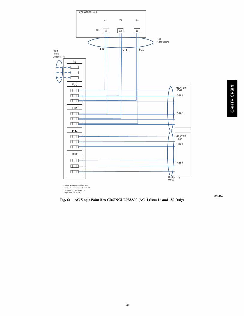
41
Unit Control Box
11 11
TapConductors
FieldPowerConductors
HEATER 294A
CIR 1
CIR 2
HEATER 294A
CIR 1
CIR 2
Heater 14Wires
Factory wiring connects load-sideof TB to line-side terminals on FU2-5.This wiring not illustrated for simplicity in this figure.
ULBKLB
11 12 13TB1
YEL
BLK YEL BLU
TB
FU2
FU3
FU4
FU5
C13464
Fig. 61 -- AC Single Point Box CRSINGLE053A00 (AC--1 Sizes 16 and 180 Only)
CRHTR,CRSIN

42
APPENDIX BAC--3 50LC COOLING APPLICATIONS
SPBCRSINGLEnnnA00
50LC Unit Sizes04---06 07 08---12
NONE Fig. 62037 Fig. 63038 Fig. 64047 Fig. 65 Fig. 68049 Fig. 66, Fig. 67 Fig. 69050 Fig. 71, Fig. 72051 Fig. 70
Unit Control BoxC
11 11
13
13
FieldPowerConductors
Unit DisconnectMOCP 60-A Max
HEATER
HeaterWires
BLK BLU
BLU
YEL
BLK
IFTB
C13450
Fig. 62 -- AC--3 No Single Point Box
Unit Control Box
C11 11
13
Unit DisconnectMOCP 60-A Max
TapConductors
FieldPowerConductors
50LC 004-006SPB 037A
BLK YEL BLU
BLK
13
ULBKLB
IFTB
HEATERWIRES
HEATER#2
IF USED
HEATER#1TB
BLUYEL
C13461
Fig. 63 -- AC--3 Single Point Box CRSINGLE037A00
CRHTR,CRSIN

43
13 13
Unit Control Box
C
11 11
TapConductors
HEATER
HEATER
Heater 104 #2if used
Heater 104 #1or Heater 105
HeaterWires
Factory wiring connects line-sideof TBF to line-side terminals on FB.This wiring not illustrated for simplicity in this figure.
13
ULBKLB
IFTB
BLK YEL BLU
FIELDPOWERCONNECTIONS
FieldTap Power Conductors
TBF
FB1
C13451
Fig. 64 -- AC--3 Single Point Box CRSINGLE037A00
Unit Control Box
11 11
Unit DisconnectMOCP 60-A Max
TapConductors
FieldPowerConductors
BLK YEL BLU
BLK
ULBKLB
HEATERWIRES
(321:CIR #2)
HEATER
(321A:CIR #1)
11 12 13TB3
YEL
TB
YEL
C13452
Fig. 65 -- AC--3 Single Point Box CRSINGLE047A00, Size 07
CRHTR,CRSIN

44
Unit Control Box
11 11
Field TapPower ConductorsConductors
HEATER 317A
HeaterWires
Factory wiring connects line-sideof TB to line-side terminals on FB.This wiring not illustrated for simplicity in this figure.
BLK
ULBKLB
11 12 13TB3
YEL
TBF
FB1
C13453
Fig. 66 -- AC--3 Single Point Box CRSINGLE049A00, Size 07
CRHTR,CRSIN

45
Unit Control Box
11 11
FieldPower TapConductors Conductors
HEATER 318A
CIR 1
CIR 2
HeaterFactory wiring connects line-side Wiresof TB to line-side terminals on FB.This wiring not illustrated for simplicity in this figure.
BLK
ULBKLB
11 12 13TB3
YEL
TBF
FB1
C13454
Fig. 67 -- AC--3 Single Point Box CRSINGLE049A00 Size 07
Unit Control Box
11 11
Unit DisconnectMOCP 60-A Max
TapConductors
FieldPowerConductors
BLK YEL BLU
BLK
ULBKLB
HEATERWIRES
(295A:CIR #2)
HEATER
(295A:CIR #1)
11 12 13TB1
YEL
HEATER
HEATER#2
IF USED
TB
YEL
C13456
Fig. 68 -- AC--3 Single Point Box CRSINGLE047A00 Sizes 08--12
CRHTR,CRSIN

46
Unit Control Box
11 11
Field TapPower ConductorsConductors
HEATER HEATER #1 CIR 1
Factory wiring connects line-sideof TB to line-side terminals on FB.This wiring not illustrated for simplicity in this figure.
BLK
ULBKLB
11 12 13TB1
YEL
HEATERWIRES
TBF
FB1
HEATER#2IF USED
CIR2
C13457
Fig. 69 -- AC--3 Single Point Box CRSINGLE049A00, Sizes 08--12
Unit Control Box
11 11
Field TapPower ConductorsConductors
HEATER CIR 1
HEATER #2
Factory wiring connects line-sideof TB to line-side terminals on FB.This wiring not illustrated for simplicity in this figure.
BLK
ULBKLB
11 12 13TB1
YEL
HEATERWIRES
FB1
TBF
FB1
CIR 2
C13458
Fig. 70 -- AC--3 Single Point Box CRSINGLE051A00, Sizes 08--12
CRHTR,CRSIN

47
Unit Control Box
11 11
FU2HEATER 295A
CIR #1
FU3
CIR #2
TapConductors
FieldPowerConductors
BLK
ULBKLB
HEATERWIRES
11 12 13TB1
YEL
YEL
TB
C13459
Fig. 71 -- AC--3 Single Point Box CRSINGLE050A00, Sizes08--12
CRHTR,CRSIN

48
Unit Control Box
11 11
TB
FU2HEATER #1
FU3HEATER 295A
CIR #1
CIR #2
TapConductors
FieldPowerConductors
BLK
ULBKLB
HEATERWIRES
11 12 13TB1
YEL
YEL
BLK
YEL
BLU
C13460
Fig. 72 -- AC--3 Single Point Box CRSINGLE050A00, Sizes 08--12
CRHTR,CRSIN

49
APPENDIX CHP--1, HP2 HEAT PUMP APPLICATIONS
SPBCRSINGLEnnnA00
HP---1 Units HP---2 Units04---07036---072
08---09090---102
12120
14150
04---06036---060
07072
08---09090---102
12120
1---Phase (See page 14 for conversion instructions)040 Fig. 73041 Fig. 74
3---PhaseNone Fig. 48* Fig. 48*037 Fig. 49* Fig. 49*038 Fig. 75 Fig. 75039 Fig. 76 Fig. 76042 Fig. 48*043 Fig. 75 Fig. 75045 Fig. 76 Fig. 76047 Fig. 49* Fig. 49* Fig. 49* Fig. 49* Fig. 49*049 Fig. 77 Fig. 78 Fig. 77 & 78 Fig. 78050 Fig. 79 Fig. 79 Fig. 80 Fig. 79 Fig. 80051 Fig. 81 Fig. 82 Fig. 83 Fig. 81 & 82 Fig. 83052 Fig. 84 Fig. 84 Fig. 85 Fig. 84 Fig. 85053 Fig. 86 Fig. 87 Fig. 88 Fig. 86 & 87 Fig. 88054 Fig. 89 Fig. 90 Fig. 91 Fig. 91
* Figure is in Appendix A
YELBLK
C13481
Fig. 73 -- AC 1--Phase Single Point Box CRSINGLE040A00
CRHTR,CRSIN

50
Unit Control BoxC
11 1111 2311 11
Field TapPower ConductorsConductors
11 23
FU2
BLK + REDHTR 1
FU3
BLK + RED
BLU + YEL
HTR 2
BLK + RED
BLU + YEL
HeaterFactory wiring connects line-side Wiresof FU2 to line-side terminals on FU3.
BLU + YEL
YELBLK
C13482
Fig. 74 -- HP 1--Phase Single Point Box CRSINGLE041A00
Unit Control Box C IFC
!! !!
FU2
HTR
7
TapConductors
FieldPowerConductors
HeaterWires
Factory wiring connects line-sideof FU2 to line-side terminals on FU3.This wiring not illustrated for simplicity in this figure.
BLUBLK YEL
11 13 11 13
FU3
C10497
Fig. 75 -- Heat Pump Single Point Box CRSINGLE038A00 & CRSINGLE043A00
CRHTR,CRSIN
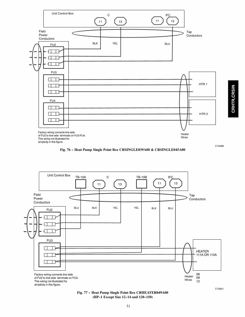
51
Unit Control BoxC IFC
!! !!
FU2
HTR 1
HTR 2
HeaterWires
Factory wiring connects line-sideof FU2 to line-side terminals on FU3-FU4.This wiring not illustrated for simplicity in this figure.
TapConductors
FieldPowerConductors
BLUBLK YEL
11 13 11 13
FU3
FU4
C10498
Fig. 76 -- Heat Pump Single Point Box CRSINGLE039A00 & CRSINGLE045A00
Unit Control BoxC IFC
FU2
HEATER 117A OR 110A
08 09 12
:
TB-10A
HeaterWires
Factory wiring connects line-sideof FU2 to line-side terminals on FU3.This wiring not illustrated for simplicity in this figure.
TapConductors
FieldPowerConductors
11 13 11 13
BLU BLUBLK BLKYEL YEL
TB-10B
FU3
C10501
Fig. 77 -- Heat Pump Single Point Box CRHEATER049A00(HP--1 Except Size 12--14 and 120--150)
CRHTR,CRSIN

52
Unit Control BoxC2 C1 IFC
FU2
FU3
HEATER 117A OR 110A
11 13 11 13 13
TB-10
TAPCONDUCTORS
FIELDPOWER
CONDUCTOR
BLUBLK YEL BLUBLK YEL
Factory wiring connects line-sideof FU2 to line-side terminals on FU3.This wiring not illustrated for simplicity in this figure.
HEATERWIRES
C10568
Fig. 78 -- Heat Pump Single Point Box CRHEATER049A00(HP--1 Size 12 and 120 Only)
Unit Control Box C IFC
TB
FU2
HEATER 116A
HEATER 1 HEATER 114A
08 08 09 09 12 12
NOTE: ALL HEATERS CONNECT TO FU3
!!"7"711 13 13
TapConductors
FieldPowerConductors
BLU BLUBLK BLKYEL YEL
Factory wiring connects line-sideof TB to line-side terminals on FU2-FU3.This wiring not illustrated for simplicity in this figure.
HeaterWires
6 Wires
FU3
C10502
Fig. 79 -- Heat Pump Single Point Box CRHEATER050A(HP--1 Except Size 14 and 150)
CRHTR,CRSIN

53
Unit Control Box
TB
FU2
HEATER CIR 1 289A
CIR 2 HEATER 292A
14 14
NOTE: ALL HEATERS CONNECT TO FU3
11 12 13
TB1
BLUBLK YEL
HEATERWIRES
6 WIRES
TAPCONDUCTORS
FIELDPOWER
CONDUCTOR
Factory wiring connects line-sideof TB to line-side terminals on FU2-FU3.This wiring not illustrated for simplicity in this figure.
FU3
C10569
Fig. 80 -- Heat Pump Single Point Box CRHEATER050A00(HP--1 Size 14 Only and 150 Only)
!"
Unit Control BoxC IFC
FU2
FU3
CIR 1
FU4HEATER 112A
CIR 2
11 13 11 13
HeaterWires
Factory wiring connects line-sideof FU2 to line-side terminals on FU3-FU4.This wiring not illustrated for simplicity in this figure.
BLU BLUBLK BLKYEL YEL
TapConductors
FieldPowerConductors
TB-10A TB-10B
C10503
Fig. 81 -- Heat Pump Single Point Box CRHEATER051A00(HP--1 Except Size 12--14 and 120--150)
CRHTR,CRSIN

54
Unit Control Box C2 TB-10 C1 IFC
FU2
HEATER 112A
CIR 1
HEATER 117A or
CIR 2 110A
11 13 11 13 13
BLUBLK YEL BLUBLK YEL
Factory wiring connects line-sideof FU2 to line-side terminals on FU3-FU4.This wiring not illustrated for simplicity in this figure.
HEATERWIRES
TAPCONDUCTORS
FIELDPOWER
CONDUCTOR
FU3
FU4
C10570
Fig. 82 -- Heat Pump Single Point Box CRHEATER051A00(Size 12 Only and 121)
Unit Control Box
FU2
FU3
FU4 HEATER 291A
HEATERWIRES
TAPCONDUCTORS
FIELDPOWER
CONDUCTOR
Factory wiring connects line-sideof FU2 to line-side terminals on FU3-FU4.This wiring not illustrated for simplicity in this figure.
11 12 13
BLUBLK YEL
TB1
C10571
Fig. 83 -- Heat Pump Single Point Box CRHEATER051A00(HP--1 Sizes 14 and 150 Only)
CRHTR,CRSIN

55
!"
Unit Control Box C IFC
TB
FU3
HEATER 1
HEATER 2
08 09 12
HeaterWiresFactory wiring connects line-side
of TB to line-side terminals on FU2-FU4.This wiring not illustrated for simplicity in this figure.
TapConductors
FieldPowerConductors
11 13 13
BLUBLK YEL
FU4
FU2
C13483
Fig. 84 -- Heat Pump Single Point Box CRHEATER052A00(HP--1 Except Size 14 and 150)
CRHTR,CRSIN

56
Unit Control Box
TB
FU2
FU3
CIR 1
FU4 HEATER 294A
CIR 2
11 12 13
TB1
BLUBLK YEL
HEATERWIRES
TAPCONDUCTORS
FIELDPOWER
CONDUCTOR
Factory wiring connects line-sideof TB to line-side terminals on FU2-FU4.This wiring not illustrated for simplicity in this figure.
C10572
Fig. 85 -- Heat Pump Single Point Box CRHEATER052A00(Size 14 and 150 Only)
CRHTR,CRSIN

57
Unit Control BoxC IFC
TB
FU2
FU3
CIR 1
FU4HEATER 112A
CIR 2
FU5
HEATER 117A
Factory wiring connects line-sideof TB to line-side terminals on FU2-FU5.This wiring not illustrated for simplicity in this figure.
TB-10BTB-10A
11 13 11 13
TapConductors
FieldPowerConductors
HeaterWires
BLU BLUBLK BLKYEL YEL
C10505
Fig. 86 -- Heat Pump Single Point Box CRHEATER053A00(HP--1 Except Sizes 12--14 and 120--150)
CRHTR,CRSIN

58
Unit Control Box C2 C1 IFC
TB
FU2
FU3 HEATER 117A or 110A (when used)
FU4HEATER 112A
CIR 1
FU5
CIR 2
TB-10
11 1113 13 13
TAPCONDUCTORSFIELD
POWERCONDUCTOR
Factory wiring connects line-sideof TB to line-side terminals on FU2-FU5.This wiring not illustrated for simplicity in this figure.
BLUBLK YEL BLUBLK YEL
HEATERWIRES
C10573
Fig. 87 -- Heat Pump Single Point Box CRHEATER053A00(HP--1 Size 12 and 120 Only)
CRHTR,CRSIN

59
Unit Control Box
TB
FU2
FU3
FU4
HEATER 288A
CIR 1
HEATER 294A
FU5
HEATER 291A
CIR 2
HEATERWIRES
TAPCONDUCTORS
FIELDPOWER
CONDUCTOR
Factory wiring connects line-sideof TB to line-side terminals on FU2-FU5.This wiring not illustrated for simplicity in this figure.
BLUBLK YEL
11 12 13
TB1
1414
C10574
Fig. 88 -- Heat Pump Single Point Box CRHEATER053A00(HP--1 Size 14 and 150 Only)
CRHTR,CRSIN
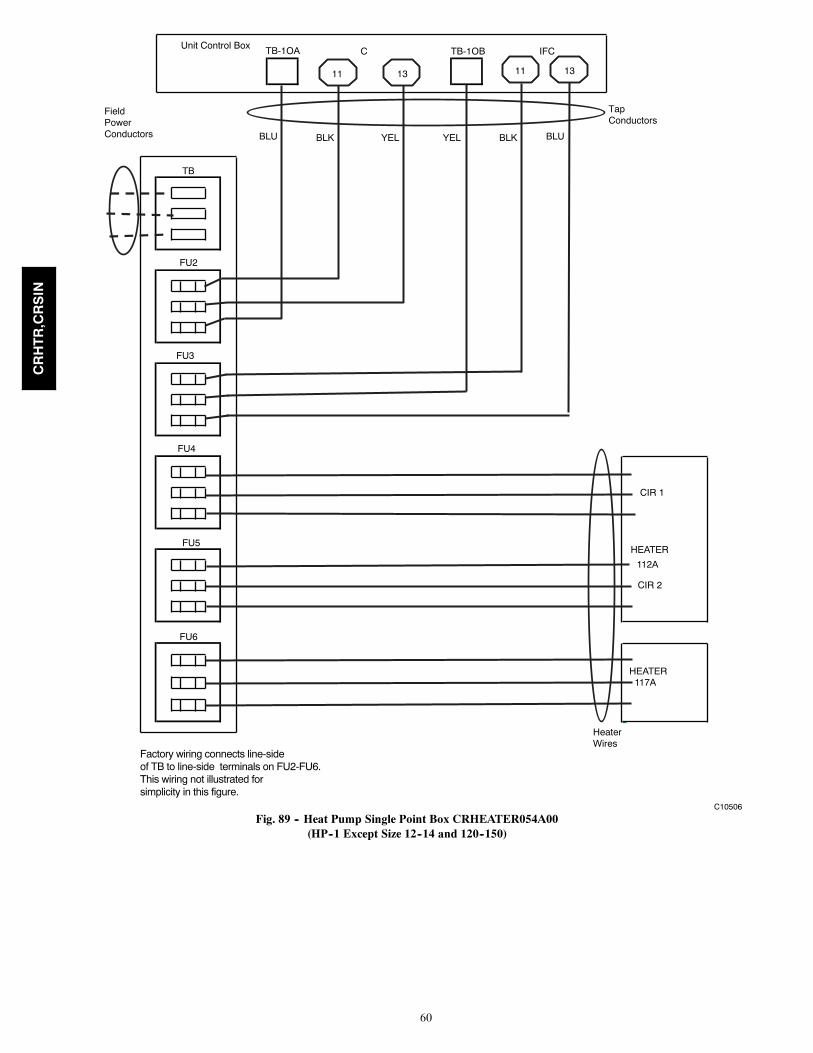
60
Unit Control BoxC TB-1OB IFC
!!!! !!!!
TapConductors
TB
FU2
FU3
FU4
CIR 1
FU5HEATER
112A
CIR 2
FU6
HEATER 117A
HeaterWires
BLU BLUBLK BLKYEL YEL
TB-1OA
11 13 11 13
FieldPowerConductors
Factory wiring connects line-sideof TB to line-side terminals on FU2-FU6.This wiring not illustrated for simplicity in this figure.
C10506
Fig. 89 -- Heat Pump Single Point Box CRHEATER054A00(HP--1 Except Size 12--14 and 120--150)
CRHTR,CRSIN

61
Unit Control Box C2 TB-10 C1 IFC$& $&
TB
FU2
FU3
FU4
CIR 1
FU5 HEATER 112A
CIR 2
FU6
HEATER 117A
or 110A
HeaterConductors
911 13 11 13 13
TAPCONDUCTORS
FIELDPOWER
CONDUCTOR
Factory wiring connects line-sideof TB to line-side terminals on FU2-FU6.This wiring not illustrated for simplicity in this figure.
BLUBLK YEL BLUBLK YEL
C10575
Fig. 90 -- Heat Pump Single Point Box CRHEATER054A00(HP--1 Sizes 12 and 120 Only)
CRHTR,CRSIN

62
Unit Control Box
TB
FU2
FU3
FU4
HEATER 288A or 291A
FU5
CIR 1
HEATER 294A
FU6
CIR 2
11 12
TB1
13
BLUBLK YEL
TAPCONDUCTORS
FIELDPOWER
CONDUCTOR
HEATERWIRES
Factory wiring connects line-sideof TB to line-side terminals on FU2-FU6.This wiring not illustrated for simplicity in this figure.
14
C10576
Fig. 91 -- Heat Pump Single Point Box CRHEATER054A00(HP--1 Size 14 and 150 Only)
CRHTR,CRSIN

63
Unit Control BoxC IFCC C
11 1111
TapConductors
FieldPower
TB
TapConductors
FieldPowerConductors ULBKLB
YEL + BLU
BLK + RED
Unit DisconnectMOCP 60-A Max
HEATER#2
YEL + BLU
BLK + RED#2
IF USED
SPB037A
YEL + BLU
BLK + RED
HeaterWires
SPB037A
HEATER
13
C13471
Fig. 92 -- 1--PH/DNU
13 13
Unit Control BoxUnit Control BoxC IFC
11 11 13
Field TapPower ConductorsConductors
11
FU2HEATER
FU3HEATER
RED + BLK
RED + BLK
YEL + BLU
HEATER
SPB 040AHeaterWires
RED + BLK
YEL + BLU
Wires
Factory wiring connects line-sideof FU2 to line-side terminals on FU3This wiring not illustrated for simplicity in this figure.
C13472
Fig. 93 -- 1--PH/DNU
CRHTR,CRSIN
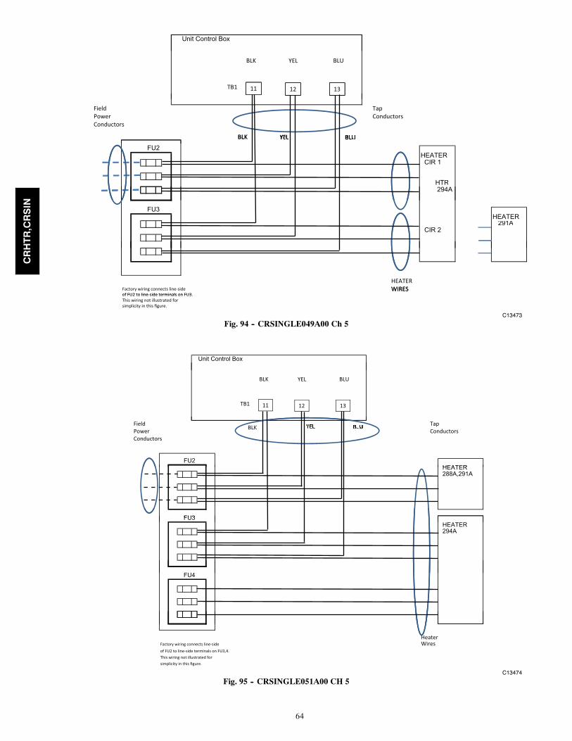
64
13 13
Unit Control Box
11 11
ULBKLB
11 12 13TB1
YEL
Field TapPower ConductorsConductors
BLK
FU2HEATERCIR 1
HTR294A
BLK
FU3HEATER
291ACIR 2
Factory wiring connects line-sideof FU2 to line-side terminals on FU3
HEATERWIRES
of FU2 to line-side terminals on FU3.This wiring not illustrated for simplicity in this figure.
WIRES
C13473
Fig. 94 -- CRSINGLE049A00 Ch 5
13 13
Unit Control Box
11 11
ULBKLB
11 12 13TB1
YEL
Field TapPower ConductorsConductors
FU2HEATER
BLK
HEATER288A,291A
FU3FU3 HEATER294A
FU4
HeaterFactory wiring connects line-side Wiresof FU2 to line-side terminals on FU3,4.This wiring not illustrated for simplicity in this figure.
C13474
Fig. 95 -- CRSINGLE051A00 CH 5
CRHTR,CRSIN

65
13 13
Unit Control Box
ULBKLB YEL
11 11
TapConductors
Field BLUBLK
11 12 13TB1
PowerConductors
TB
BLUBLK
FU2HEATER294A
CIR 1
FU3FU3
CIR 2
FU4
HEATER294A
CIR 1
FU5
CIR 2
Heater 14Wires
Factory wiring connects load-sideof TB to line-side terminals on FU2-5.This wiring not illustrated for simplicity in this figure.
C13475
Fig. 96 -- CRSINGLE053A00 CH 5
CRHTR,CRSIN

66
13
Unit Control BoxUnit Control BoxC IFC
11 11 1311 13 11
BLK + RED
HeaterWiresFactory wiring connects line-side
of FU2 to line-side terminals on FU3
YEL + BLU
BLK + RED
WiresFactory wiring connects line-sideof FU2 to line-side terminals on FU3.This wiring not illustrated for simplicity in this figure.
Tap ConductorsFieldPowerConductors
FU2
FU3
SPB 040A
HEATER
C13476
Fig. 97 -- HP 1--PH CRSINGLE041A00
CRHTR,CRSIN

67
APPENDIX
DELECTRIC
HEATERDATA
NOTES:
1.“Usedon”dataissimplifiedtoindicategeneralcabinetsize
use.
Noteveryheaterisapproved
foruseon
everyunitsize.Consultproductdata,electronicselectionprograms
andpricepagesfordetailed
usagedata.
2.Shaded
areasindicateno
usageofheaterinthisrowon
unittype
inthiscolumn.
ELECTRIC
HEATERDATA
(CRHEATERnnna00)
SALES
PKGNBR
HEATER
MODELNBR
VOLTS
KW
FLA1-PH
FLA3-PH
QTYCIRS
Usedon
AC-1
HP-1
AC-2
HP-2
AC-3
101A
001A
208/240
3.3/4.4
15.9/18.6
9.4/10.6
1
04-07
(036-072)
04-07
(036-072)
04-06
(036-060)
04-06
(036-060)
04-06
102A
002A
4.9/6.5
23.6/27.3
13.8/15.7
1
103B
003B
6.5/8.7
31.2/36.2
18.1/20.7
1
104B
004B
7.9/10.5
38.0/43.8
22.2/25.3
1
105A
005A
12.1/16.0
--33.6/38.4
1
106A
006A
480
6.0
--7.0
1
107A
007A
8.8
--10.5
1
108A
008A
11.5
--13.8
1
109A
009A
14.0
--16.8
1
110A
010A
208/240
12.0/16.0
--33.3/38.5
1
08-14
(090-150)
08-12
(090-121)
07-12
(072-120)
07-09
(072-102)
111A
011A
18.6/24.8
--51.7/59.7
2
112A
012A
24.0/32.0
--66.7/77.1
2
113A
013A
480
16.5
--19.8
1
114A
014A
27.8
--33.4
1
115A
015A
33.0
--39.7
1
116A
016A
13.9
--16.7
1
117A
017A
208/240
7.8/10.4
--21.7/25.0
1
118A
018A
600
18.0
--17.0
1
119A
019A
36.0
--34.0
1
CRHTR,CRSIN

68
APPENDIX
D(CONT.)
ELECTRIC
HEATERDATA
SALES
PKGNBR
HEATER
MODELNBR
VOLTS
KW
FLA1-PH
FLA3-PH
QTYCIRS
Usedon
AC-1
HP-1
AC-2
HP-2
AC-3
264A
264A
208/240
4.9/6.5
--13.5/15.6
1
07 (072)
07 (072)
265A
265A
480
6--
7.2
1
266A
266A
11.5
--13.8
1
267A
267A
14.0
--16.8
1
268A
268A
480
23.0
--27.7
2
269A
269A
25.5
--30.7
2
288A
288A
208/240
7.5/10
--21.3/24.5
1
16 (180)
14 (150)
14 (150)
12 (120)
08-12
289A
289A
480
10--
12.1
1
290A
290A
600
10--
9.6
1
291A
291A
208/240
12.4/16.5
--34.5/39.7
1
292A
292A
480
16.5
--19.9
1
293A
293A
600
16.5
--15.9
1
294A
294A
208/240
25.2/33.5
--70.0/80.6
2
295A
295A
480
33.5
--40.3
2
296A
296A
600
33.5
--32.2
2
297A
297A
600
10.0
9.6
104-05
(036-048)
04-05
(036-048)
298A
298A
15,0
14.4
105-06
(048-060)
04-06
(036-060)
299A
299A
28.0
26.9
107 (072)
07 (072)
07
301A
301A
600
23.0
23.0
206 (060)
06 (060)
06
CRHTR,CRSIN

69
APPENDIX
D(CONT.)
ELECTRIC
HEATERDATA
SALES
PKGNBR
HEATER
MODELNBR
VOLTS
KW
FLA1-PH
FLA3-PH
QTYCIRS
Usedon
AC-1
HP-1
AC-2
HP-2
AC-3
308A
308A
600
18.0
17.3
1
07
316A
316A
208/240
4.9/6.5
13.6/15.6
107 (072)
07 (072)
317A
317A
208/240
12.0/16.0
33.4/38.5
1
07 (072)
07 (072)
318A
318A
18.8/24.8
52.1/60.1
2
319A
319A
480
6.0
7.2
1
320A
320A
14.0
16.8
1
321A
321A
25.5
30.1
1
322A
322A
600
28.0
26.9
1CRHEATERXXXX00
CRHTR,CRSIN

70
Copyright 2013 CAC / BDP D 7310 W. Morris St. D Indianapolis, IN 46231 Edition Date: 10/13
Manufacturer reserves the right to change, at any time, specifications and designs without notice and without obligations.
Catalog No:IIK---CRHTRSIN01---07
Replaces: IIK---CRHTRSIN01---06