installation instructions & user manual zip hydroboilinstallation instructions & user manual...
TRANSCRIPT
1Installation instructions & user manual 804545UK V2.03 Aug 2018 - Zip Hydroboil
Technical support Tel: 0345 6 005 005 Email: [email protected] www.zipwater.co.uk
Installation instructions & user manual
Zip HydroboilOn wall boiling water.
Model number:
301552, 303552, 305552, 307552, 310552, 315552, 325552, 340552
02 Installation instructions & user manual 804545UK V2.03 Aug 2018 - Zip Hydroboil
Technical support Tel: 0345 6 005 005 Email: [email protected] www.zipwater.co.uk
Table of contents
Intended Use ................................................................................................................................ 2Warnings and precautions ........................................................................................................... 3Before installation ......................................................................................................................... 4Technical specification ................................................................................................................. 5
Installation instructions Before you begin ............................................................................................................... 6
Step 1 - Position the Hydroboil Positioning ......................................................................................................................... 6
Step 2 - Fasten to the wall Fastening .......................................................................................................................... 6
Step 3 - Connection and venting Plumbing connections ....................................................................................................... 8 Venting .............................................................................................................................. 8 Electrical connections ....................................................................................................... 9
Step 4 - Assembly Assembly ........................................................................................................................... 10
Step 5 - Commission the Hydroboil Earth continuity verification ................................................................................................. 11 Turn the mains power and water on .................................................................................... 11
Trouble shootingTrouble shooting table .................................................................................................................. 12
OperationOperation ..................................................................................................................................... 12
Appendix Mounting templates ...................................................................................................................... 13Spare parts ................................................................................................................................... 15End of life disposal ....................................................................................................................... 19Cleaning ....................................................................................................................................... 19Contact details ............................................................................................................................. 20
Intended use
This appliance is intended to be used in commercial applications such as:• Staff kitchens, shops, offices and other working environments.• Small hotels and bed and breakfast type environments.• Catering and similar non-retail applications.
For list of models falling within the scope of this manual, please refer to the Technical specification table, page 5.
03Installation instructions & user manual 804545UK V2.03 Aug 2018 - Zip Hydroboil
Technical support Tel: 0345 6 005 005 Email: [email protected] www.zipwater.co.uk
WARNINGS AND PRECAUTIONS
!This manual contains important safety and installation instructions for the Zip Hydroboil.Please read all warnings, installation requirements and installation instructions before installing any Zip Hydroboil. This system must be installed in accordance with water supply byelaws, current IEE regulations and relevant local authority byelaws.
Warnings• The Zip Hydroboil must be earthed. The resistance of the earth connection from each exposed metal part
must be less than 1Ω.• All installation and service work must be completed by trained and suitably qualified tradespeople. Faulty
operation due to unqualified persons working on this product, or any other Zip product may void warranty coverage.
• Never attempt to install a Zip Hydroboil instant boiling water heater without reading all of the applicable instructions.
• Do not remove the cover of the Hydroboil under any circumstances without first isolating it from the power supply.
• In hard water areas mineral scale accumulation in the boiling chamber of the Zip Hydroboil may become a problem, consideration should be given to the maintenance required. A suitable form of water treatment may be necessary.
• The Zip Hydroboil instant boiling water heater is not intended for use by young children or infirm people without supervision.
• Young children should be prevented from having access to ensure that they are not able to use or play with the Hydroboil.
• Do not use strong, corrosive or abrasive cleaners to clean the case of the Hydroboil.• The ambient temperatures this Hydroboil must operate within is 5ºC - 50ºC.• The Hydroboil is intended only for indoor use and should never be installed outdoors or be exposed to the
elements of nature.• This Hydroboil must not be positioned in an area that may be cleaned by a water jet. The Hydroboil must not
be cleaned by a water jet.• As the installer, it is your responsibility to supply (if necessary) and install all valves as required by local
regulations and relevant standards.• The Hydroboil is rated for 230V 50Hz AC operation.• Due to the process of continuous improvement, Zip reserves the right to change details mentioned in this
manual, without notice.• Visit www.zipwater.co.uk to ensure you have the latest copy of this document.
04 Installation instructions & user manual 804545UK V2.03 Aug 2018 - Zip Hydroboil
Technical support Tel: 0345 6 005 005 Email: [email protected] www.zipwater.co.uk
WARNINGS AND PRECAUTIONS
SafetyThis appliance is not intended for use by persons (including children) with reduced physical, sensory or mental capabilities, or lack of experience and knowledge, unless they have been given supervision or instruction concerning use of the appliance by a person responsible for their safety. For products sold in Europe, this appliance can be used by children aged from 8 years and above and persons with reduced physical, sensory or mental capabilities or lack of experience and knowledge if they have been given supervision or instruction concerning use of the appliance in a safe way and understand the hazards involved. Children should be supervised to ensure that they do not play with the appliance. Cleaning and user maintenance shall not be made by children.This appliance is intended to be used in commercial applications.
Qualifications If the power cable is damaged it must be repaired only by a qualified technician. To avoid hazards, all installation procedures must be carried out by a suitably qualified tradesperson.
Venting Occasionally steam and / or boiling water may discharge through a vent outlet or the tap. Ensure the tap body is located so the tap outlet safely dispenses into the drip tray or sink bowl area, and that the vent is plumbed to a safe location, see page 8.
LiftingTake care when lifting. The Hydroboil may exceed safe lifting limits. If you feel this is beyond your personal capabilities, please seek assistance with the lift. Do not lift the Hydroboil by the tap, fascia or any of its connections. Refer to the Technical specification, page 5 for the weight of the product.
Positioning It is important to ensure the Hydroboil is positioned in an accessible area. The Hydroboil must have it’s base mounted in a horizontal position.
!
!
Before installation
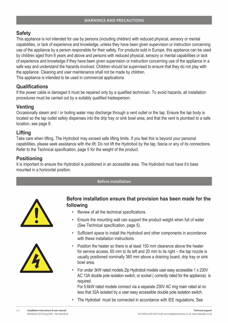
Before installation ensure that provision has been made for the following
• Review of all the technical specifications.• Ensure the mounting wall can support the product weight when full of water
(See Technical specification, page 5).• Sufficient space to install the Hydroboil and other components in accordance
with these installation instructions.• Position the heater so there is at least 150 mm clearance above the heater
for service access, 65 mm to its left and 20 mm to its right – the tap nozzle is usually positioned nominally 360 mm above a draining board, drip tray or sink bowl area.
• For under 3kW rated models Zip Hydroboil models user easy accessible 1 x 230V AC 13A double pole isolation switch, or socket ( correctly rated for the appliance) is required. For 5.6kW rated models connect via a separate 230V AC ring main rated at no less that 32A isolated by a user easy accessible double pole isolation switch.
• The Hydroboil must be connected in accordance with IEE regulations. See
05Installation instructions & user manual 804545UK V2.03 Aug 2018 - Zip Hydroboil
Technical support Tel: 0345 6 005 005 Email: [email protected] www.zipwater.co.uk
Before installation
Technical specification, page 5 for power ratings.Note Check cable and plumbing against inlet /outlet positions before proceeding.
• A wholesome water supply connection with isolating valve within reach of the Hydroboil and positioned so that the stop cock will not be obstructed when the Hydroboil is installed.
• Vent / outlet drainage to a draining board, drip tray or sink bowl area.• A wholesome cold water supply with a minimum working pressure of:
(see Technical specification, below min. / max. water supply pressure).• A 0.35 MPa (3.5 bar) pressure limiting valve supplied must be fitted if the incoming mains water pressure is
likely to exceed 0.5 MPa (5.0 bar).• The Hydroboil must be placed with its base in a horizontal position.
IMPORTANT! Do not proceed with the installation if these requirements are not met.
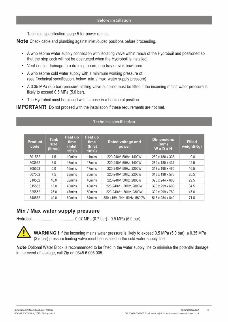
Technical specification
Product code
Tank size
(litres)
Heat up time (Inlet 15°C)
Heat up time
(Inlet 10°C)
Rated voltage and power
Dimensions (mm)
W x D x H
Filled weight(Kg)
301552 1.5 10mins 11mins 220-240V, 50Hz, 1400W 289 x 180 x 335 10.0303552 3.0 16mins 17mins 220-240V, 50Hz, 1400W 289 x 180 x 431 12.5305552 5.0 16mins 17mins 220-240V, 50Hz, 2200W 318 x 198 x 465 16.5307552 7.5 23mins 23mins 220-240V, 50Hz, 2200W 318 x 198 x 578 20.5310552 10.0 38mins 40mins 220-240V, 50Hz, 2800W 390 x 244 x 600 29.5315552 15.0 40mins 43mins 220-240V~, 50Hz, 2800W 390 x 299 x 600 34.5325552 25.0 47mins 50mins 220-240V~, 50Hz, 2800W 390 x 299 x 780 47.0340552 40.0 60mins 64mins 380-415V, 2N~, 50Hz, 5600W 515 x 284 x 840 71.0
Min / Max water supply pressureHydroboil.........................................0.07 MPa (0.7 bar) - 0.5 MPa (5.0 bar)
WARNING ! If the incoming mains water pressure is likely to exceed 0.5 MPa (5.0 bar), a 0.35 MPa (3.5 bar) pressure limiting valve must be installed in the cold water supply line.
Note Optional Water Block is recommended to be fitted in the water supply line to minimise the potential damage in the event of leakage, call Zip on 0345 6 005 005.
!
06 Installation instructions & user manual 804545UK V2.03 Aug 2018 - Zip Hydroboil
Technical support Tel: 0345 6 005 005 Email: [email protected] www.zipwater.co.uk
Installation instructions
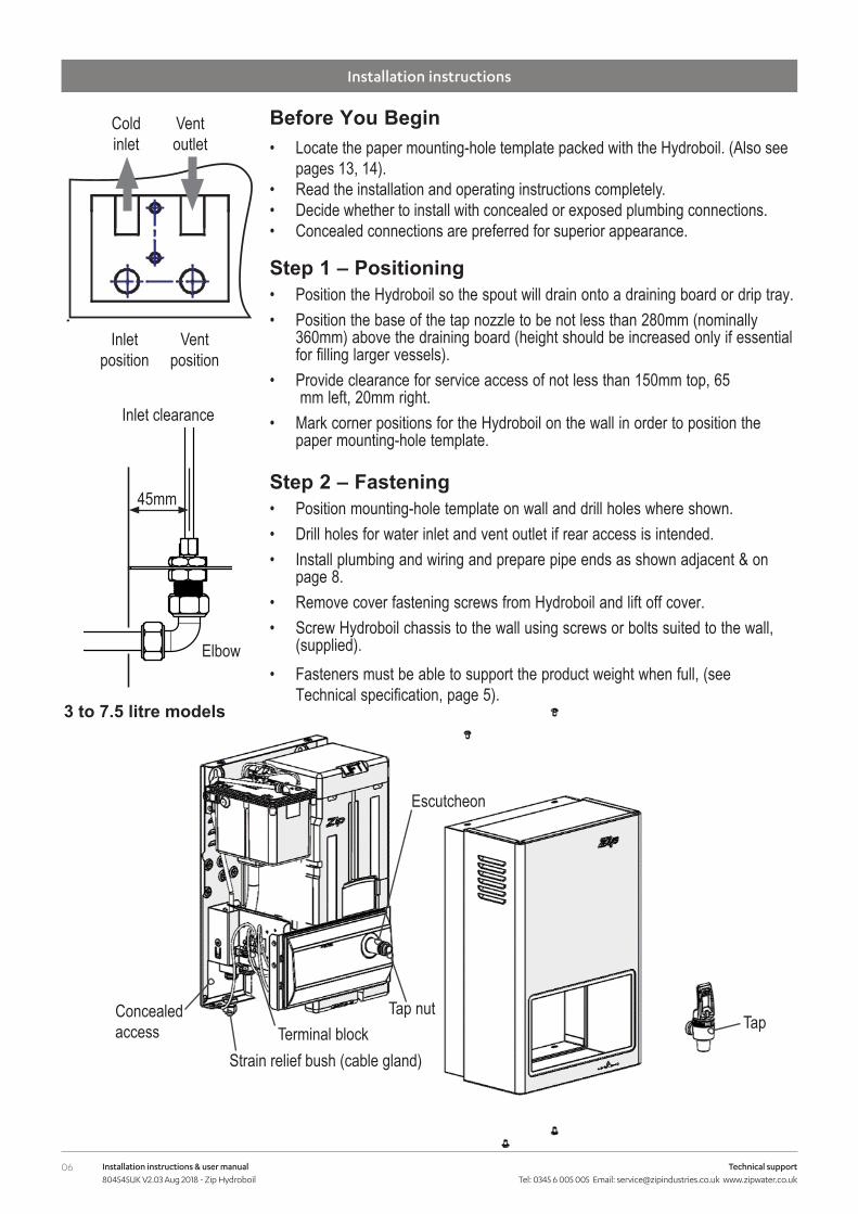
Before You Begin• Locate the paper mounting-hole template packed with the Hydroboil. (Also see
pages 13, 14).• Read the installation and operating instructions completely.• Decide whether to install with concealed or exposed plumbing connections. • Concealed connections are preferred for superior appearance.
Step 1 – Positioning• Position the Hydroboil so the spout will drain onto a draining board or drip tray.• Position the base of the tap nozzle to be not less than 280mm (nominally
360mm) above the draining board (height should be increased only if essential for filling larger vessels).
• Provide clearance for service access of not less than 150mm top, 65 mm left, 20mm right.
• Mark corner positions for the Hydroboil on the wall in order to position the paper mounting-hole template.
Step 2 – Fastening• Position mounting-hole template on wall and drill holes where shown.• Drill holes for water inlet and vent outlet if rear access is intended.• Install plumbing and wiring and prepare pipe ends as shown adjacent & on
page 8.• Remove cover fastening screws from Hydroboil and lift off cover.• Screw Hydroboil chassis to the wall using screws or bolts suited to the wall,
(supplied).• Fasteners must be able to support the product weight when full, (see
Technical specification, page 5).
45mm
Elbow
Inlet clearance
Coldinlet
Ventoutlet
Inletposition
Ventposition
3 to 7.5 litre models
Strain relief bush (cable gland)Terminal block
Escutcheon
Tap nutTapConcealed
access
07Installation instructions & user manual 804545UK V2.03 Aug 2018 - Zip Hydroboil
Technical support Tel: 0345 6 005 005 Email: [email protected] www.zipwater.co.uk
Installation instructions
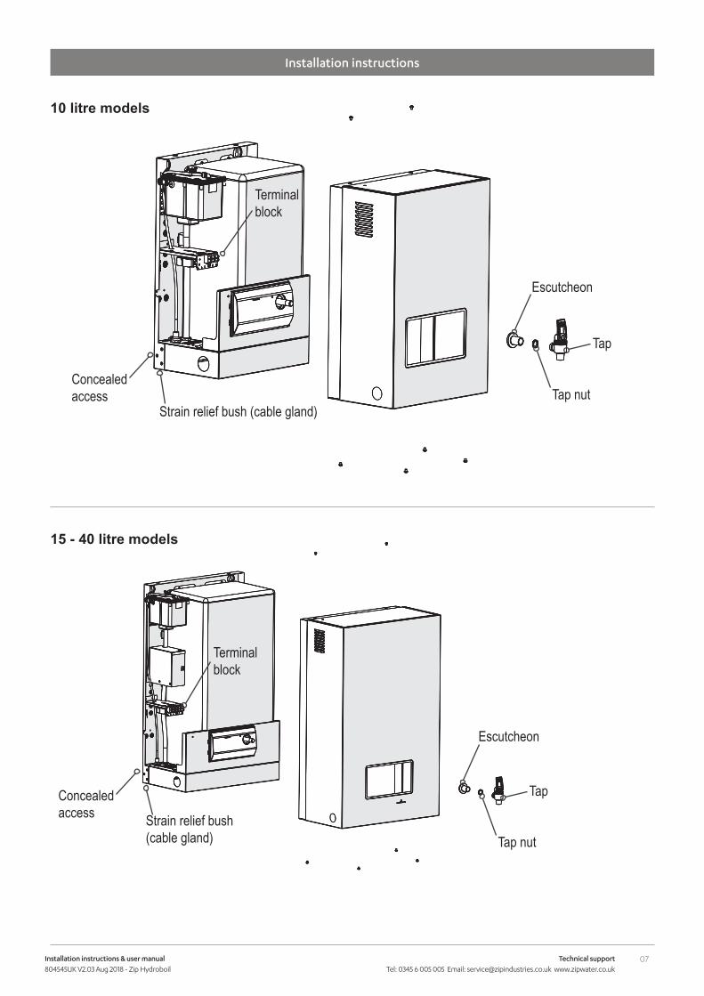
10 litre models
15 - 40 litre models
Strain relief bush (cable gland)
Terminal block
Escutcheon
Tap nut
Tap
Escutcheon
Tap nut
Tap
Terminal block
Strain relief bush (cable gland)
Concealed access
Concealed access
08 Installation instructions & user manual 804545UK V2.03 Aug 2018 - Zip Hydroboil
Technical support Tel: 0345 6 005 005 Email: [email protected] www.zipwater.co.uk
installation instructions
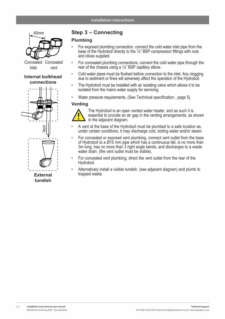
Step 3 – ConnectingPlumbing• For exposed plumbing connection, connect the cold water inlet pipe from the
base of the Hydroboil directly to the ½” BSP compression fittings with nuts and olives supplied.
• For concealed plumbing connections, connect the cold water pipe through the rear of the chassis using a ½” BSP capillary elbow.
• Cold water pipes must be flushed before connection to the inlet. Any clogging due to sediment or fines will adversely affect the operation of the Hydroboil.
• The Hydroboil must be installed with an isolating valve which allows it to be isolated from the mains water supply for servicing.
• Water pressure requirements. (See Technical specification , page 5).Venting
The Hydroboil is an open vented water heater, and as such it is essential to provide an air gap in the venting arrangements, as shown in the adjacent diagram.
• A vent at the base of the Hydroboil must be plumbed to a safe location as, under certain conditions, it may discharge cold, boiling water and/or steam.
• For concealed or exposed vent plumbing, connect vent outlet from the base of Hydroboil to a Ø15 mm pipe which has a continuous fall, is no more than 3m long, has no more than 3 right angle bends, and discharges to a waste water drain. (the vent outlet must be visible).
• For concealed vent plumbing, direct the vent outlet from the rear of the Hydroboil.
• Alternatively install a visible tundish. (see adjacent diagram) and plumb to trapped waste.
45mm
Concealed vent
Concealed Inlet
Internal bulkhead connections
External tundish
Vent
!
09Installation instructions & user manual 804545UK V2.03 Aug 2018 - Zip Hydroboil
Technical support Tel: 0345 6 005 005 Email: [email protected] www.zipwater.co.uk
Installation instructions
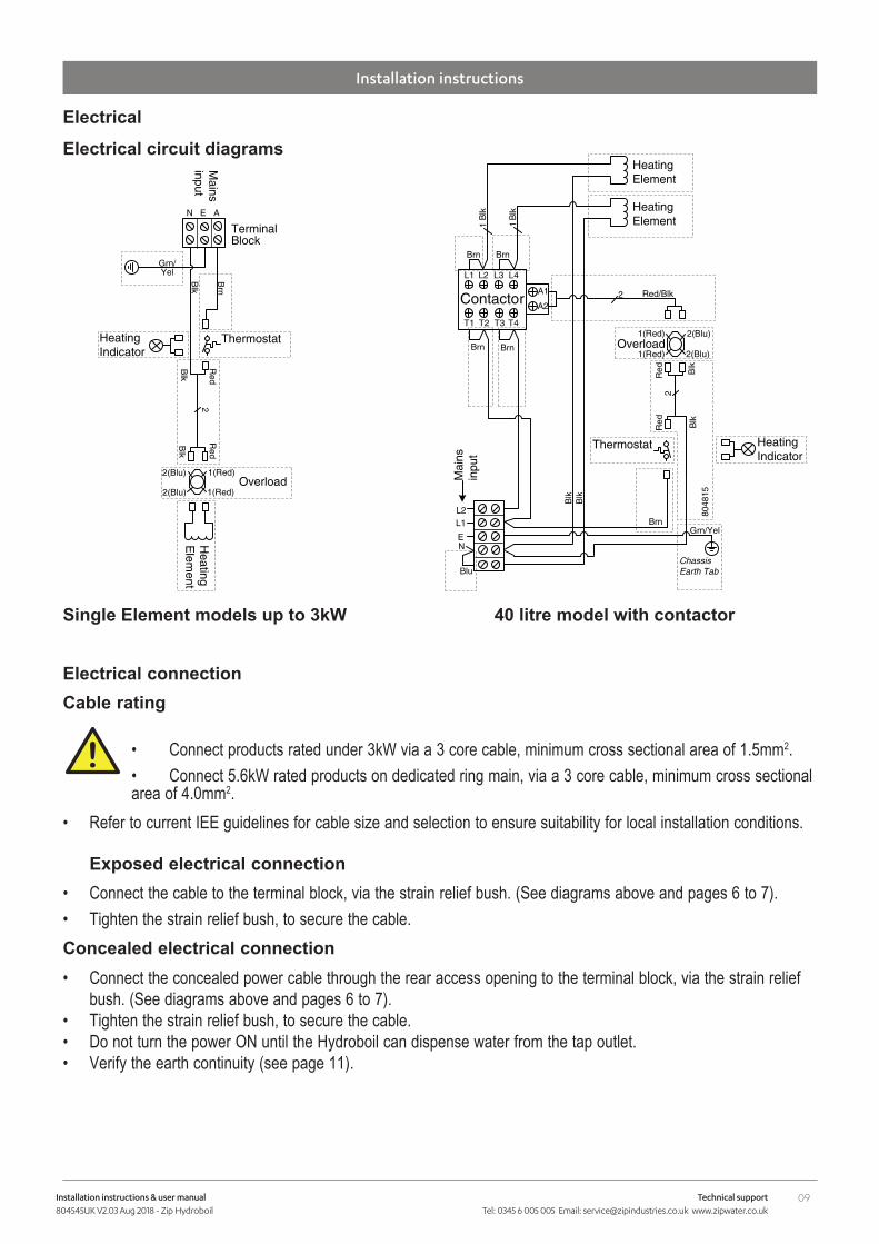
Electrical connectionCable rating
• Connect products rated under 3kW via a 3 core cable, minimum cross sectional area of 1.5mm2.• Connect 5.6kW rated products on dedicated ring main, via a 3 core cable, minimum cross sectional area of 4.0mm2.
• Refer to current IEE guidelines for cable size and selection to ensure suitability for local installation conditions. Exposed electrical connection
• Connect the cable to the terminal block, via the strain relief bush. (See diagrams above and pages 6 to 7).• Tighten the strain relief bush, to secure the cable.Concealed electrical connection • Connect the concealed power cable through the rear access opening to the terminal block, via the strain relief
bush. (See diagrams above and pages 6 to 7).• Tighten the strain relief bush, to secure the cable.• Do not turn the power ON until the Hydroboil can dispense water from the tap outlet.• Verify the earth continuity (see page 11).
!
Single Element models up to 3kW 40 litre model with contactor
Electrical circuit diagrams
Electrical
Thermostat
Heating
Elem
ent
N E A
2(Blu) 1(Red)Overload
1(Red)2(Blu)
Blk
Red
Red
Blk
TerminalBlock
Brn
Blk
2
Grn/Yel
Heating Indicator
Mains
input
Heating Element
Mai
ns
inpu
t
1(Red) 2(Blu)
2(Blu)1(Red)Overload
Chassis Earth Tab
NE
L2
L1 L2 L3 L4
T1 T2 T3 T4
ContactorA1
A22
Heating Element
Red/Blk
L1
Brn Brn
11B
lk
Blk
Blk
Grn/Yel
Brn Brn
Blk
Blu
Thermostat
Blk
Red
Red Blk
2
Brn
8048
15
Heating Indicator
10 Installation instructions & user manual 804545UK V2.03 Aug 2018 - Zip Hydroboil
Technical support Tel: 0345 6 005 005 Email: [email protected] www.zipwater.co.uk
Installation instructions
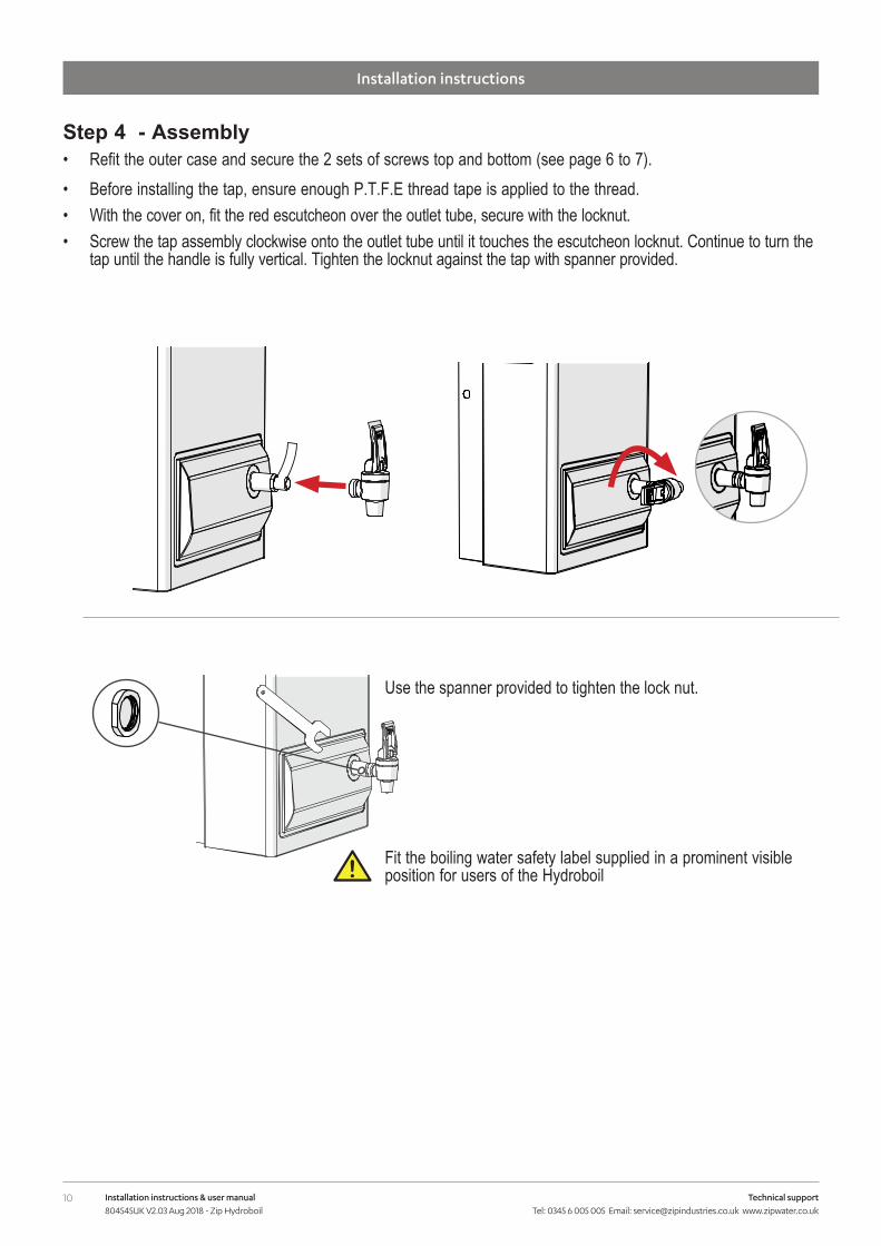
Use the spanner provided to tighten the lock nut.
Fit the boiling water safety label supplied in a prominent visible position for users of the Hydroboil!
Step 4 - Assembly• Refit the outer case and secure the 2 sets of screws top and bottom (see page 6 to 7).• Before installing the tap, ensure enough P.T.F.E thread tape is applied to the thread. • With the cover on, fit the red escutcheon over the outlet tube, secure with the locknut.• Screw the tap assembly clockwise onto the outlet tube until it touches the escutcheon locknut. Continue to turn the
tap until the handle is fully vertical. Tighten the locknut against the tap with spanner provided.
11Installation instructions & user manual 804545UK V2.03 Aug 2018 - Zip Hydroboil
Technical support Tel: 0345 6 005 005 Email: [email protected] www.zipwater.co.uk
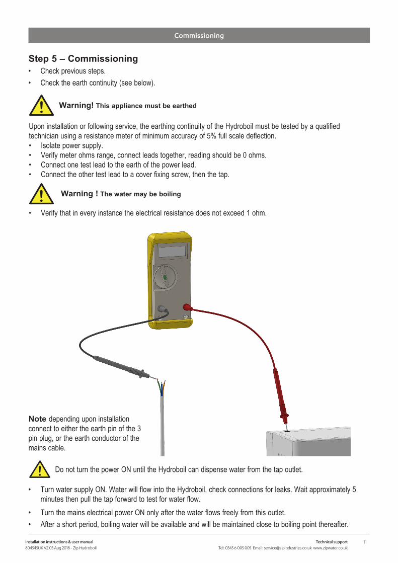
Step 5 – Commissioning • Check previous steps. • Check the earth continuity (see below).
Upon installation or following service, the earthing continuity of the Hydroboil must be tested by a qualified technician using a resistance meter of minimum accuracy of 5% full scale deflection.• Isolate power supply.• Verify meter ohms range, connect leads together, reading should be 0 ohms.• Connect one test lead to the earth of the power lead.• Connect the other test lead to a cover fixing screw, then the tap.
Warning ! The water may be boiling
• Verify that in every instance the electrical resistance does not exceed 1 ohm.
Warning! This appliance must be earthed
• Turn water supply ON. Water will flow into the Hydroboil, check connections for leaks. Wait approximately 5 minutes then pull the tap forward to test for water flow.
• Turn the mains electrical power ON only after the water flows freely from this outlet. • After a short period, boiling water will be available and will be maintained close to boiling point thereafter.
Do not turn the power ON until the Hydroboil can dispense water from the tap outlet.
Commissioning
!
!
!
Note depending upon installation connect to either the earth pin of the 3 pin plug, or the earth conductor of the mains cable.

12 Installation instructions & user manual 804545UK V2.03 Aug 2018 - Zip Hydroboil
Technical support Tel: 0345 6 005 005 Email: [email protected] www.zipwater.co.uk
Trouble-shooting table
Symptom Possible cause Solution
Fails to dispense water.Water isolating valve turned off.
Blocked filter, blocked meter tube, blocked strainer, jammed ball
valve assy, airlock in transfer tube.
Check water supply valve.Contact Zip authorised agent.
Water not boiling.No power.
Faulty thermostat, faulty element, faulty cut-out.
Check power supply.Contact Zip authorised agent.
Runs out of boiling water and fails to refill.
Outlet tap drips.Overflow from vent.
Excessive steam from vent.Power “on” but no heat.
Overload repeatedly tripping with excessive steam.
Overload repeatedly tripping without
excessive steam.
Internal adjustment,blocked vent,
vented incorrectly (see page 8)
Contact Zip authorised agent.
Operation
Tap OperationBoiling water• Zip Hydroboil is fitted with a two-way tap for instant boiling water.• For instant boiling water, gently pull the top of the tap forward.• Boiling water will flow until the tap handle is released. • This operation gives fingertip flow control for safe filling of cups and mugs.• To fill larger vessels such as teapots and saucepans, rotate the tap 180º and depress it until it locks into a
horizontal position. Boiling water will flow until the tap is returned to its normal vertical position. • This operation allows the vessel to be filled without holding your hand where it may be affected by steam.
13Installation instructions & user manual 804545UK V2.03 Aug 2018 - Zip Hydroboil
Technical support Tel: 0345 6 005 005 Email: [email protected] www.zipwater.co.uk
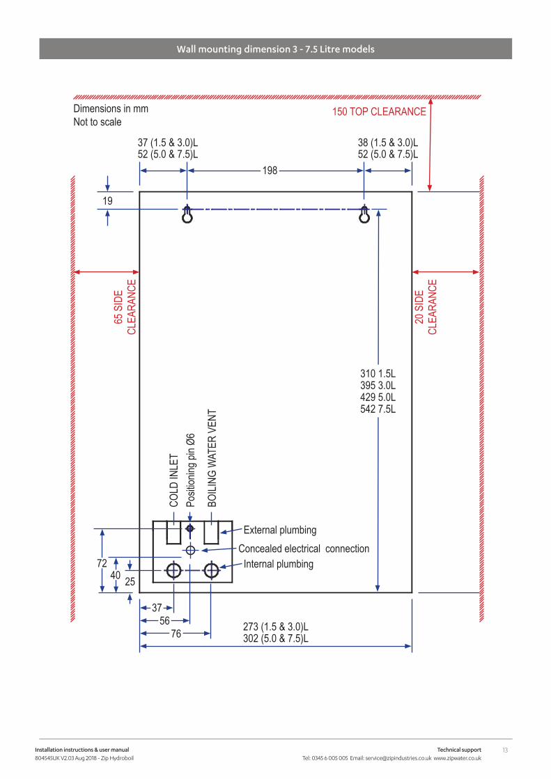
Wall mounting dimension 3 - 7.5 Litre models
37 (1.5 & 3.0)L
19852 (5.0 & 7.5)L
38 (1.5 & 3.0)L52 (5.0 & 7.5)L
19
395 3.0L429 5.0L542 7.5L
310 1.5L
37
76 273 (1.5 & 3.0)L302 (5.0 & 7.5)L
56
COLD
INLE
T
BOILI
NG W
ATER
VEN
T
254072
Posit
ioning
pin Ø
6
External plumbing
Internal plumbing
150 TOP CLEARANCE65
SID
E CL
EARA
NCE
Dimensions in mmNot to scale
20 S
IDE
CLEA
RANC
E
Concealed electrical connection
14 Installation instructions & user manual 804545UK V2.03 Aug 2018 - Zip Hydroboil
Technical support Tel: 0345 6 005 005 Email: [email protected] www.zipwater.co.uk
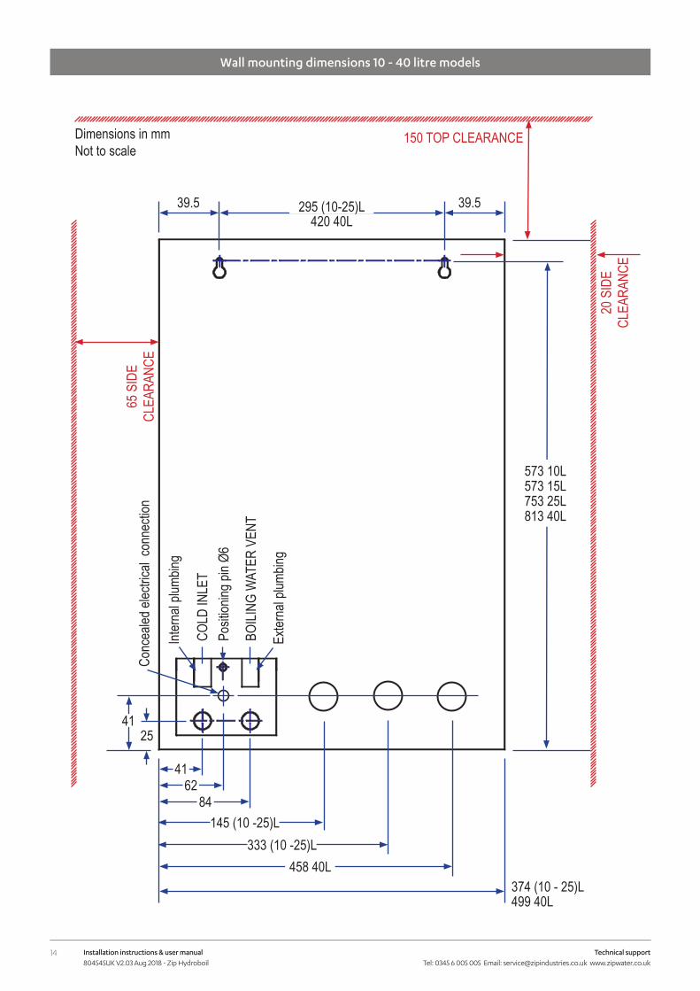
Wall mounting dimensions 10 - 40 litre models
295 (10-25)L39.5
573 15L753 25L813 40L
573 10L
41
84
374 (10 - 25)L499 40L
62
COLD
INLE
T
BOILI
NG W
ATER
VEN
T
2541
Posit
ioning
pin Ø
6
Exter
nal p
lumbin
g
Inter
nal p
lumbin
g
150 TOP CLEARANCE65
SID
E CL
EARA
NCE
Dimensions in mmNot to scale
20 S
IDE
CLEA
RANC
E
Conc
ealed
elec
trical
conn
ectio
n
420 40L39.5
145 (10 -25)L333 (10 -25)L
458 40L
15Installation instructions & user manual 804545UK V2.03 Aug 2018 - Zip Hydroboil
Technical support Tel: 0345 6 005 005 Email: [email protected] www.zipwater.co.uk
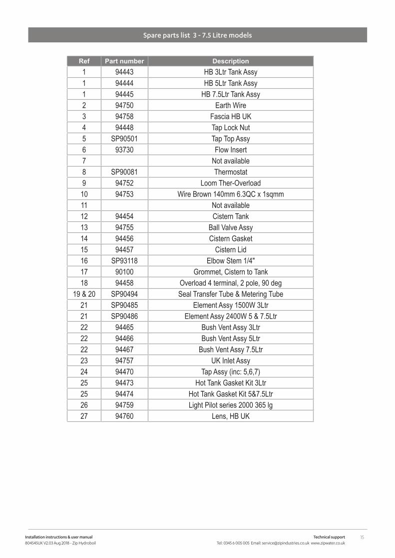
Spare parts list 3 - 7.5 Litre models
Ref Part number Description1 94443 HB 3Ltr Tank Assy1 94444 HB 5Ltr Tank Assy1 94445 HB 7.5Ltr Tank Assy2 94750 Earth Wire3 94758 Fascia HB UK4 94448 Tap Lock Nut5 SP90501 Tap Top Assy6 93730 Flow Insert7 Not available8 SP90081 Thermostat9 94752 Loom Ther-Overload
10 94753 Wire Brown 140mm 6.3QC x 1sqmm11 Not available12 94454 Cistern Tank13 94755 Ball Valve Assy14 94456 Cistern Gasket15 94457 Cistern Lid16 SP93118 Elbow Stem 1/4"17 90100 Grommet, Cistern to Tank18 94458 Overload 4 terminal, 2 pole, 90 deg
19 & 20 SP90494 Seal Transfer Tube & Metering Tube21 SP90485 Element Assy 1500W 3Ltr21 SP90486 Element Assy 2400W 5 & 7.5Ltr22 94465 Bush Vent Assy 3Ltr22 94466 Bush Vent Assy 5Ltr22 94467 Bush Vent Assy 7.5Ltr23 94757 UK Inlet Assy24 94470 Tap Assy (inc: 5,6,7)25 94473 Hot Tank Gasket Kit 3Ltr25 94474 Hot Tank Gasket Kit 5&7.5Ltr26 94759 Light Pilot series 2000 365 lg27 94760 Lens, HB UK
16 Installation instructions & user manual 804545UK V2.03 Aug 2018 - Zip Hydroboil
Technical support Tel: 0345 6 005 005 Email: [email protected] www.zipwater.co.uk
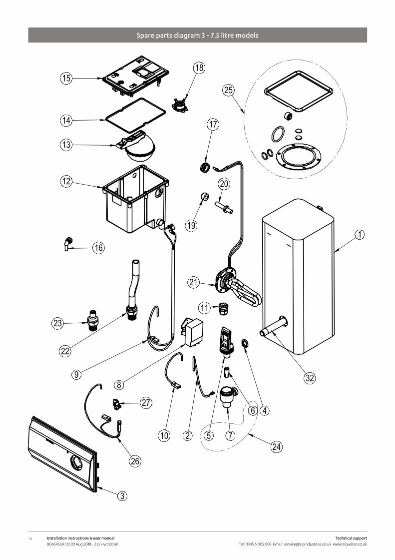
Spare parts diagram 3 - 7.5 litre models
1
46
75210
8
23
22
9
19
17
1815
14
13
12
11
20
16
25
32
24
21
3
26
27

17Installation instructions & user manual 804545UK V2.03 Aug 2018 - Zip Hydroboil
Technical support Tel: 0345 6 005 005 Email: [email protected] www.zipwater.co.uk
Spare parts list 10 - 40 litre models
Ref Part number Description1 94766 UK HB 10Ltr Tank Assy1 94767 UK HB 15Ltr Tank Assy1 94768 UK HB 25Ltr Tank Assy1 94769 UK HB 40Ltr Tank Assy2 SP90491 Cleaning Hole Cover Kit HB/AB3 SP90492 Drain Cap and Seal Kit HB/AB4 94448 Tap Lock Nut5 SP90501 Tap Top Assy6 93730 Flow Insert7 Not available8 SP90081 Thermostat9 94447 Kit Escutcheon
10 94758 Fascia HB11 94470 Tap Assy (inc: 5,6,7)12 94454 Cistern Tank13 94755 Ball Valve Assy14 94456 Cistern Gasket15 94457 Cistern Lid16 SP93118 Elbow Stem 1/4"17 94609 Contactor 4 Pole18 94458 Overload 4 terminal, 2 pole, 90 deg19 94460 Seal Transfer Tube20 94510 Metering Tube21 SP90530 Kit 3.0kW Element LBW22 94762 Bush Vent Assy 10-15Ltr22 94763 Bush Vent Assy 25Ltr22 94764 Bush Vent Assy 40Ltr23 94757 Inlet Assy24 90100 Kit Grommets Cistern25 94759 Light Pilot series 2000 365 lg26 94760 Lens, HB UK27 94625 Kit Loom Contactor to Overload 40lt
18 Installation instructions & user manual 804545UK V2.03 Aug 2018 - Zip Hydroboil
Technical support Tel: 0345 6 005 005 Email: [email protected] www.zipwater.co.uk
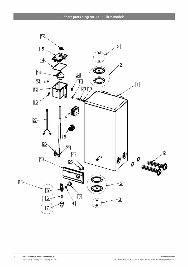
Spare parts diagram 10 - 40 litre models
19Installation instructions & user manual 804545UK V2.03 Aug 2018 - Zip Hydroboil
Technical support Tel: 0345 6 005 005 Email: [email protected] www.zipwater.co.uk
End of life disposal
Cleaning
The use of this crossed out wheeled bin logo indicates that this product needs to be disposed of separately to any other household waste.Within each of the European Union member countries, provisions have been made for collection and recycling of unwanted electrical and electronic equipment. In order to help preserve our environment we ask that you dispose of this product correctly. Please contact Zip Customer Service on 0345 6 005 005 for advice.
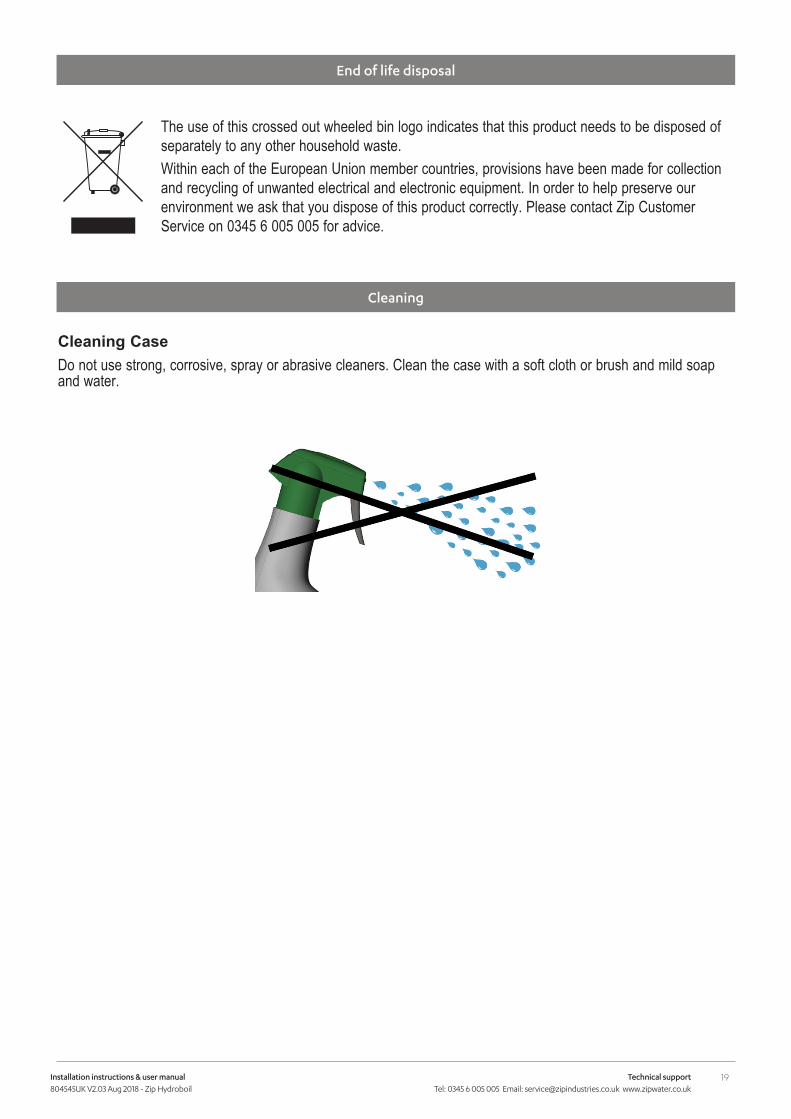
Cleaning CaseDo not use strong, corrosive, spray or abrasive cleaners. Clean the case with a soft cloth or brush and mild soap and water.

20 Installation instructions & user manual 804545UK V2.03 Aug 2018 - Zip Hydroboil
Technical support Tel: 0345 6 005 005 Email: [email protected] www.zipwater.co.uk
Zip Water UK
14 Bertie Ward Way, Dereham, Norfolk NR19 1TE
0345 6 005 005 [email protected]
www.zipwater.co.uk