installation instructions - yazaki · pdf fileabsorption chiller-heater ... foundation 13...
TRANSCRIPT

GAS-FIRED DOUBLE-EFFECT ABSORPTION CHILLER-HEATER
This product is a gas-fired double-effect absorption unit which provides chilled water
for cooling or hot water for heating in central plant-type air conditioning systems. Units with nominal refrigeration capacities of 150 and 200 tons are complete with operating and safety controls. The chiller-heater is fitted with a low NOx burner, automatic ignition system, power combustion blower, and proportional firing control.
CONTENTS GENERAL Page
GENERAL 2
MODEL DESIGNATION 2
STANDARD SPECIFICATIONS 3
EQUIPMENT DIMENSIONS 4
INTERNAL WIRING DIAGRAM 6
INSTALLATION
RECEIVING 9
RIGGING 10
CENTER OF GRAVITY 11
INSTALLATION CLEARANCES 12
LOCATION 13
FOUNDATION 13
Page
LEVELING 14
COMBUSTION AIR SUPPLY 14
VENTING 15
PIPING 17
TYPICAL SYSTEM DESIGN 18
CHILLED/HOT WATER PIPING 19
COOLING WATER PIPING 19
FREEZE PROTECTION 20
GAS SUPPLY PIPING 21
ELECTRICAL 22
TYPICAL FIELD WIRING DIAGRAM 24
WATER QUALITY 26
INSTALLATION CHECK &
REQUEST FOR STARTUP 26
INSTALLATION INSTRUCTIONS
CH-MG150
CH-MG200

2
GENERAL
This equipment should only be
installed by trained and qualified personnel who are familiar with absorption chillers. All precautions in these instructions, as well as on tags and labels attached to the unit, must be observed to ensure the safety of the personnel and maintain warranty validation.
Each Yazaki absorption chiller-heater
has been evacuated, charged with lithium bromide and water solution, and run tested prior to leaving the factory.
Field wiring connections are located
on the right side of the unit when facing the front of the unit. Piping connections, including gas piping, are all located at the rear of the unit.
After the equipment has been
installed, a Yazaki Authorized Service Provider (ASP) must check the installation and supervise or conduct the initial startup and operation of the unit.
CAUTION
THE YAZAKI WARRANTY WILL BE VOIDED IF THE FOLLOWING RESTRICTIONS ARE NOT OBSERVED:
1. DO NOT OPEN ANY VACUUM VALVES WITHOUT A PROPER EVACUATION ASSEMBLY ATTACHED TO THEM AS SUCH ACTION WILL RESULT IN LOSS OF VACUUM AND INTRODUCTION OF GASES TO THE INTERIOR OF THE MACHINE WHICH COULD CAUSE CORROSION.
2. ALWAYS HANDLE THE EQUIPMENT WITH CARE AND MAINTAIN IN A NEAR-VERTICAL POSITION DURING RIGGING.
3. DISCONNECT GAS PIPING FROM EQUIPMENT WHEN PRESSURE TESTING AT 0.5 PSI OR GREATER IN ORDER TO AVOID DAMAGE TO THE GAS VALVES.
4. DO NOT ATTEMPT TO START THE SYSTEM WITHOUT SUPERVISION FROM A YAZAKI AUTHORIZED SERVICE PROVIDER (ASP).
MODEL DESIGNATION
CH-MG ### Double-Effect Absorption Chiller-Heater (MG Series) Cooling Capacity: 150 = 150 ton, 200 = 200 ton

3
STANDARD SPECIFICATIONS SPECIFICATIONS English (Metric) CH-MG150 CH-MG200
Capacity Cooling MBTU/hr (kW/hr) 1,800 (527.5) 2,400 (703.4)
Heating MBTU/hr (kW/hr) 1,245 (364.9) 1,660 (486.5)
Chilled/Hot Water
Chilled Water Temperature
Inlet °F (°C) 53.6 (12)
Outlet °F (°C) 44.6 (7)
Hot Water Temperature
Inlet °F (°C) 132.8 (56)
Outlet °F (°C) 140.0 (60)
Evaporator Pressure Loss PSI (kPa) 10.5 (72.4) 9.2 (63.4)
Maximum Operating Pressure PSI (kPa) 113.9 (785)
Rated Water Flow GPM (l/s) 399.4 (25.2) 532.6 (33.6)
Water Retention Volume Gal (liters) 48 (181.7) 69 (261.2)
Cooling Water
Heat Rejection MBTU/hr (kW/hr) 3,045 (892.4) 4,060 (1189.9)
Cooling Water Temperature
Inlet °F (°C) 85.1 (29.5)
Outlet °F (°C) 94.3 (34.6)
Abs/Cond Pressure Loss PSI (kPa) 7.5 (57.1) 7.2 (49.6)
Maximum Operating Pressure PSI (kPa) 113.9 (785)
Rated Water Flow GPM (l/s) 658.6 (41.6) 878.1 (55.4)
Water Retention Volume Gal (liters) 114 (431.5) 153 (579.2)
Fuel Type of Fuel Natural Gas
Consumption MBTU/hr (kW/hr) 1,500 (439.6) 2,000 (586.1)
Electrical
Power Source 208v or 230v / 60Hz / 3-phase
Consumption kW 2.9 3.3
Minimum Circuit Amps Amps 24.4 29.0
Maximum Overcurrent Protection Amps 30 35
Capacity Control
Cooling 30-100% Proportional
Heating 30-100% Proportional
Combustion
Burner Type Low NOx Forced Draft (Proportional)
Flame Detection Flame Rod
Ignition Type Pilot w/ Intermittent Spark
Sound dB(A) 74
Dimension
Width Inches (mm) 77.0 (1957) 80.9 (2057)
Depth Inches (mm) 144.2 (3665) 147.0 (3735)
Height (without vent cap) Inches (mm) 88.2 (2240) 97.6 (2480)
Height (including vent cap) Inches (mm) 108.8 (2775) 118.1 (3000)
Piping
Chilled/Hot Water Inches 4 (Flange) 5 (Flange)
Cooling Water Inches 5 (Flange) 6 (Flange)
Gas Piping Inches 2 NPT
Weight Dry lbs (kg) 12,346 (5600) 14,330 (6500)
Operating lbs (kg) 13,698 (6213) 16,183 (7340) Note: All metric values are calculated from the Imperial values and are only approximate values.
1. Fuel Input is based on the high heat value of gas. Burner efficiency = 83%. Allowable supply gas pressure is 7”-10.5” wc. 2. Power consumption does not include external pumps or cooling tower fan motors. 3. “Width” dimension does not include Junction Box. 4. Specifications are all based upon water in all fluid circuits and fouling factor of 0.0005 ft²-hr-°F/Btu. 5. Pressure Loss ratings are +/- 10%. 6. Minimum Cooling Water flow is 100%.
Table 1 – Specifications

4
EQUIPMENT DIMENSIONS
Figure 1 – MG150 Dimensions
5
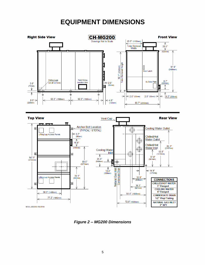
EQUIPMENT DIMENSIONS
Figure 2 – MG200 Dimensions

6
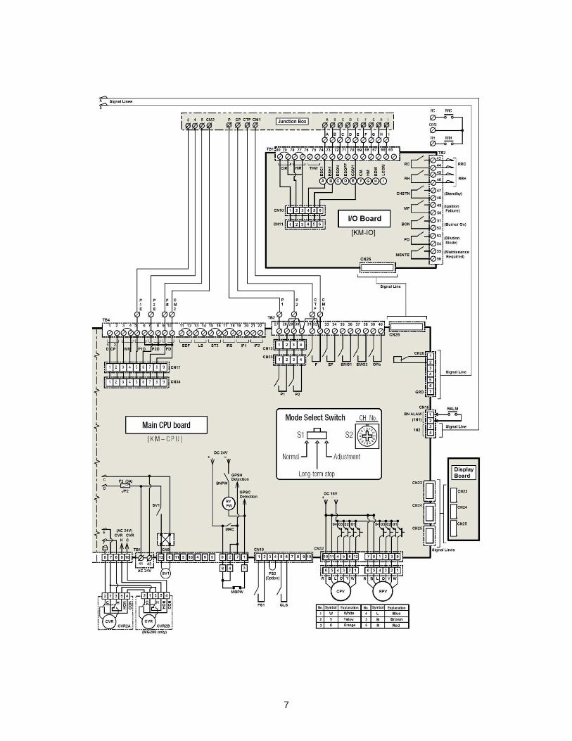
INTERNAL WIRING DIAGRAM
7

8
Table 2 – Internal Wiring Diagram Legend
KRCH relay has been replaced by the KCH relay.

9
INSTALLATION
RECEIVING
When the absorption chiller-heater is delivered, inspect it for transit damage. Should any damage have occurred, do not proceed with installation until the Yazaki distributor has been notified and any required remedial actions have been completed.
The MG-Series units are too large for the typical fork lift. Special handling procedures must be followed in order to safely remove the unit from a covered trailer. An open flat-bed trailer is preferred for easiest delivery, but is not always an option.
Remember to properly plan the route to the installation site. Also, keep in mind when choosing the site, the unit will someday have to be replaced, so be mindful of permanent and semi-permanent barriers.
The unit typically must be pulled out of a container or trailer and often must be pulled into position on site. The frame of the unit is specifically designed for the
forces due to horizontal pulling. Attach cable or acceptable equivalent to the frame only at the provided holes. No other points should be used for horizontal pulling.
Figure 3 – Horizontal Movement
Figure 4 – Hallway Clearances

10
RIGGING
The Yazaki chiller-heater is designed for overhead rigging with openings in the cabinet and holes in the equipment frame intended for such use. Ensure that the crane being used is proper for the mass to be lifted.
When rigging for overhead lift, remove the four cardboard or sheet metal covers on the top panel to expose the lugs for rigging. Attach shackle bolts to these
lugs. Bring the four individual rigging cables together at a point high enough that the angle between the rigging line and the top of the unit is no less than 60°, as shown in the drawings below.
Once the unit is in final position, locate the four top panel blanks which are included in the accessories box. Install these blanks in order to keep the cabinet weatherproof.
Cable (from Top
View)
Minimum Length ft (m)
A 11.5 (3.5)
B 11.0 (3.3)
C 9.75 (3.0)
D 8.75 (2.7)
Figure 5 – Rigging

11
Model Center of Gravity Position Operating
Weight
A - inches(mm) B - inches(mm) C - inches(mm) lbs(kg)
CH-MG150 40.2 (1020) 34.3 (870) 67.3 (1710) 13,700 (6,215)
CH-MG200 43.7 (1110) 36.2 (920) 65.7 (1670) 16,200 (7,350)
Weight Distribution CH-MG150 CH-MG200
Dry - lbs(kg) Operating - lbs(kg) Dry - lbs(kg) Operating - lbs(kg)
Front Left 1,528 (693) 1,688 (766) 1,831 (831) 2,074 (941)
Front Right 1,448 (657) 1,600 (726) 1,735 (797) 1,965 (892)
Middle Left 3,353 (1,521) 3,704 (1,681) 3,777 (1,714) 4,279 (1,941)
Middle Right 2,698 (1,224) 2,981 (1,353) 3,103 (1,408) 3,515 (1,595)
Back Left 1,746 (792) 1,929 (875) 1,985 (901) 2,249 (1,021)
Back Right 1,627 (738) 1,797 (816) 1,869 (848) 2,118 (961)
Total 12,400 (5,625) 13,700 (6,215) 14,300 (6,487) 16,200 (7,350)
Figure 6 – Center of Gravity and Corner Weights

12
INSTALLATION CLEARANCES
Figure 7 – Installation and Service Clearances

13
LOCATION
Particular care must be taken when placing the machine so as to provide adequate clearance for access to each side of the machine.
Maintenance is mostly done through the front of the unit, but in repair scenario, any panel on any side may need to be removed to access components behind them.
Further, with the shell and tube design of the MG-Series fluid circuits, it is possible to clean and/or replace tubes during the life cycle of the machine, therefore, clearance must be available to
be able to perform such maintenance and repair tasks.
Finally, as with all mechanical devices, the unit will have to be replaced someday. Keep that in mind as well when choosing the final placement site.
The minimum clearance space is shown on the chart and diagram below. Note that the tube removal clearances can be provided either in front or back. Also, it is not necessary that the 114.2” (2900 mm) clearance for tube access be provided across the entire end of the unit.
FOUNDATION
All aspects of foundation and support computations must be in accordance with national and local codes.
The chiller-heater must be mounted on a level, non-combustible foundation capable of supporting the considerable weight of the machinery. This is particularly important for rooftop installations. Always make certain the structure can support not only the chiller-heater, but also the pumps, piping, cooling towers, etc. as may be required. The rooftop area should be well-drained and be at least 7 feet (2 meters) from the edge of the roof. Anti-fall measures should always be taken if the chiller-heater is installed within 12 feet (4 meters) of the edge of the roof.
Additionally, for protection of the roofing material, it is recommended a suitable platform or walkway be provided around all sides of the unit.
If the chiller-heater is to be installed outside, but at ground level, make certain the concrete base and the soil beneath are sufficient for the task. Settling over time could cause the unit to become unlevel, which could have a serious negative impact on the performance and lifespan of the unit. Concrete foundations are recommended to be sized so that at least 12” (300 mm) extends beyond the unit in all directions to accommodate potential mounting and anchoring hardware.
Figure 8 – Foundation Detail

14
LEVELING
MG-Series units must be level in order for the fluids to be distributed properly over their respective tube bundles. There is a level bar mounted on the front of the machine right above the absorber section, near the fusible plug.
Figure 9 – Level Bar
The unit must be level to both the longitudinal and transverse alignments. In cases of multiple units installed side-by-side, the units should all be level individually as well as in respect to each other. It is essential that all leveling be
completed before any piping connections are attempted.
Use shim plates to level the machine. Shims are typically field-supplied when needed and should be of galvanized, flat, hot-rolled mild steel in dimension of at least 0.2” (5 mm) thick, 10.2” (260 mm) long, and 7.9” (200 mm) wide. When shims are required, place them under the machine tie-down points.
Figure 10 – L-Anchor Plate Detail
(all dimensions in inches)
COMBUSTION AIR SUPPLY
As with all gas-fired appliances, careful consideration must be given in regard to the provision of sufficient free air for combustion and venting. The rules for such are found in the National Fuel Gas Code, NFPA Standard 54. The code supersedes anything found in print here or in any other Yazaki documentation. What has been provided here are only guidelines to help toward proper installation of the unit.
When installed outdoors, no special provisions are usually needed in regard to combustion air. However, if the unit is in a confined area outside, some issues could arise if external forces cause a negative pressure area around the unit.
An example of such would be having the unit installed in an alcove with a strong, sustained wind blowing by along the edge of the building. Such occurrences are rare, but should be considered.
Of greater concern are indoor installations, especially in areas with more than one gas-fired appliance. Keep in mind that whatever combustion air supply is present, it must be capable of supporting every gas-fired appliance in the space while all of them operate at full capacity. Combustion air openings are also often the source for dilution air for Category I appliances, so it is recommended to consult the manuals on all appliance in the area in order to

15
ensure all requirements are being considered. Never install a gas-fired appliance in an unventilated space.
ASME Section VI – Recommended Rules for the Care and Operations of Heating Boilers, Reference 6.04” states:
“The boiler room must have adequate air supply to permit clean, safe combustion and to minimize soot formation. An unobstructed air opening should be provided. It may be sized on the basis of 1-square inch free area per 2000 BTUh maximum fuel input of combined burners located in the boiler room, or as specified in the National Fire Protection Association standards for oil and gas burner installations for the particular job. The boiler room air supply openings must be kept clear at all times.”
Figure 11 – Combustion Air Detail
VENTING
Each chiller-heater is supplied with a suitable vent cap intended for installation on the exhaust outlet when the equipment is installed outdoors. Remove the right side panel on the cabinet and attach the vent cap to the exhaust tube with ten M10 (or 3/8”) bolts (field-supplied).
Figure 12 – Factory Vent Cap
In cases where an extended vent is necessary, follow the normal venting rules. Venting the flue products safely is a key concern when installing any gas-fired appliance and Yazaki chiller-heaters are no exception. As with combustion air, rules for the proper venting of gas-fired appliances are also covered in the
National Fuel Gas Code, NFPA Section 54.
All MG-Series chiller-heaters are Category I appliances. When choosing vent material size, the chillers are classified as “fan” vent-type since the fan on the burner only assists in moving flue products through the unit. The fan does NOT provide enough force to do more than push the flue products a few feet down the vent, so it does not have enough force to qualify as Category III, side discharge venting. There are aftermarket kits that can provide Category III capability for Category I appliances should the need arise. Yazaki has no kit for this. Warranty may be void on the Yazaki chiller-heater if such a kit is used, but not installed or applied correctly. Carefully follow all instructions when applying these kits, and if necessary, contact Yazaki Energy Systems, Inc. for guidance on integration of the kit to the unit control safeties.

16
Exhaust gas volume to be handled by the vent system is listed in the chart below. The table reflects gas consumption with the burner operating at 100% fire rate with CO2 at 8.5% and O2 at 5.5% (31.8% combustion excess air). These conditions release exhaust gas on the order of 392°F (200°C) at a density of 0.011 lbs/ft³ (0.175 kg/m³).
Model Exhaust Gas Volume at 392°F (200°C)
CH-MG150 531 CFM (14.5 m³/min)
CH-MG100 707 CFM (20.0 m³/min)
A number of quick rules can be listed in regard to venting.
1. Always use B-Type double wall vent material. 2. Vent should never run downhill. 3. Vent must terminate at least 7’ (2.2m) above
public walkways. 4. Vent must terminate at least 4’ above vertically
or 10’ (3m) horizontally from openings into living areas or air intakes.
5. Vent must terminate no closer than 10’ (3m) from an inside corner unless it terminates 2’ (600mm) above said inside corner.
6. Vent should terminate at least 2’ (600mm) above the highest point within 10’ (3m), with a minimum height above the roof of 3’ (1m).
Figure 13
7. Rise (Height) should be greater than the Run (Lateral).
Figure 14
8. It is recommended that each unit be vented separately if possible. If the vent is taller than 7’ (2.2m), a barometric damper (also known as a draft regulator) may be required. The range of draft pressure allowed at the vent connection on the chiller-heater is 0.0” wc to -0.05” wc. If the draft pressure is outside of this range, a barometric damper should be used to correct this in order to prevent sooting and possible damage to the HGE.
9. Always measure draft as closely as possible to the vent outlet of the unit.
10. Maintain a minimum of 18” (460mm) separation between the ceiling and any horizontal run of vent pipe.
In instances where multiple units must be vented, and individual venting is impractical or undesirable, combined venting (Common Venting) is permitted so long as it follows proper venting rules. There will be separate and special charts for sizing common venting applications. Follow the rules given by the vent material manufacturer.
Things that do not change by manufacturer:
1. Barometric dampers (draft regulators) are no longer an option. They are required so that vent conditions of one unit do not affect the operation/venting of the other(s). Use a separate damper for each chiller-heater with the damper located as close as possible to the unit (location A in preference to location B).
Figure 15
2. Size connecting Tees properly.
Figure 16

17
3. The maximum allowable lateral length (L) is
equal to 1.5’ x diameter of the pipe in inches.
Connector Lateral Length Allowance Pipe Diameter
Inches 10 12 14 16 18
Maximum Lateral Length
Feet 15 18 21 24 27
Table 3
4. When the common pipe grows to become 7x
greater in area than any of the other interconnecting pipe, special rules will apply. Consult the pipe manufacturer for these details and/or special rules.
PIPING
After the chiller-heater has been leveled properly, the piping for the chilled/hot water and cooling water circuits may be installed. Piping arrangements should be made with care so that there is no interference with service access or panel removal. Piping should be adequately supported and braced independently of the unit so as to avoid undue strain on the unit piping
connections. Maximum allowable pressure in any fluid circuit is 113.8 PSI (785 kPa).
Piping rules and conventions used with Yazaki chiller-heaters are exactly the same as used with any other type of chiller; therefore, this installation manual will not delve deeply into piping design.
CAUTION
1. Do not exceed 113.8 PSI (785 kPa) in either the chilled/hot water or the cooling water circuits of the Yazaki chiller-heater.
2. Do not install any valves in expansion pipe line.
Thermo-wells, pressure gauges, Pete’s Plugs, etc. may be installed at the inlet and/or outlet of each fluid circuit connection to facilitate startup, future service, and routine maintenance. Strainers in each circuit, particularly the cooling water circuit, are recommended as well. These should be placed before the inlet connection of the chiller-heater.
Figure 17 – Typical System Piping

18
TYPICAL SYSTEM DESIGN
Figure 18 – Example of Single Module Installation
MULTIPLE MODULES
Figure 19 – Example of Multiple Module Installation

19
CHILLED/HOT WATER PIPING
A balance valve should be installed at the chilled/hot water outlet and a stop valve should be installed at the chilled/hot water inlet. Both valves should be placed in close proximity to the chiller-heater.
After thoroughly testing for leaks, insulate the piping circuit, ensuring an adequate vapor barrier is obtained. Be sure to allow access to any valves, wells, and ports that may be present. Also, ensure the chiller-heater panels are not restricted by the insulation.
Figure 20 – Chilled/Hot Water Piping
COOLING WATER PIPING
Cooling water should be supplied at 85°F (29.5°C) or less. The CH-MG Series can adapt to cooling water down to 65°F (18.5°C) without the need of a mixing valve. However, the inlet cooling water temperature must not be below 46.4°F (8°C) when the cooling cycle starts, nor may it drop to 46.4°F (8°C) and remain there for more than 3 minutes at any point in time. Such cases will result in the generation of error code E043. This error code will automatically reset itself once the cooling water warms above 48.2°F (9°C).
To prevent a hot slug of water from potentially damaging the cooling tower, a Cooling Water Control Valve (CWV)
should be used and set so that it bypasses into the sump of the cooling tower for the first 2 minutes of the first cooling cycle after the unit has changed over from heating mode. This same valve can also be used to divert water that is too cold into the sump of the cooling tower until the water has warmed up to an acceptable temperature.
Higher temperatures than 85°F (29.5°C) can result in a loss of capacity. In some cases, the burner will simply be able to ramp up the firing rate to compensate, but this lowers the efficiency of the unit and should be avoided. If cooling water exceeds 90°F (32°C), the refrigerant vapor may no longer condense properly, which could lead to a loss of capacity as well. If the cooling water becomes consistently too hot, the unit may lock out.
Figure 21 – Cooling Water Piping
20
If possible, the cooling tower should be installed at the same level or above the level of the chiller-heater. If this is not possible, give careful consideration to the prevention of drain-back and loss of cooling water due to overflow of the tower. Such matters must be given prior consideration by the design engineer.
As with the chilled/hot water connections, a balance valve should be installed on the cooling water inlet and a stop valve installed on the cooling water outlet. Both valves should be in close proximity to the chiller-heater. After
thoroughly testing for leaks, insulate the piping circuit, ensuring an adequate vapor barrier is obtained. Be sure to allow access to any valves, wells, and ports that may be present. Also, ensure the chiller-heater panels are not restricted by the insulation.
Additionally, there should be flush and drain valves installed between the machine and the balance/stop valves so as to allow for flushing of the absorber-condenser coils should it ever become necessary.
FREEZE PROTECTION
When the chiller-heater and/or associated piping are installed in a location that is subject to freezing conditions, appropriate anti-freeze steps must be taken. Many anti-freeze methods are available including heat tape, but the most common method in the USA is the use of glycol in the fluid loop.
Glycol may be permitted for use in Yazaki chiller-heaters with certain restrictions and observations.
1. In the chilled/hot water circuit, it should only be used during heating operation. It is not recommended for use in the chilled water circuit in cooling mode as the loss of heat transfer performance could result in tube failure under certain extreme conditions.
2. Glycol may be used in the cooling water circuit in any operating mode.
3. Do not use automotive glycol (Antifreeze) since it contains chemical additives that are inappropriate and potentially damaging to the Yazaki chiller-heater. Use only glycol appropriate for use with copper tubing.
4. Do not exceed a mixture of 50% by weight.
5. Be aware that loss of performance will result when glycol is used. In higher concentrations, the impact can be very significant.
6. Propylene Glycol is preferred wherever possible. It has very similar anti-freeze characteristics to Ethylene Glycol, but is non-toxic. It is also less viscous than Ethylene Glycol, which reduces the required pump power.
7. Use of glycol can cause the unit to operate at a slightly higher internal temperature since heat transfer is dampened. This may result in depletion of inhibitor at a faster rate than what may be perceived as normal.

21
GAS SUPPLY PIPING
Before connecting the gas supply pipe, check the UNIT NAMEPLATE to confirm that it is compatible with the gas type available. Note that there is no LP version of the CH-MG UL Series.
The gas piping must be selected and installed in accordance with local building codes and the National Fuel Gas Code (ANSI Z233.1, latest edition). Typically, the pipe size is selected at the maximum gas pressure input and with 0.5 inches water column maximum pressure loss between the gas meter and the equipment.
CAUTION
TO AVOID DAMAGE TO THE GAS VALVES IN THE CHILLER-HEATER, DISCONNECT THE GAS PIPE WHEN THE TEST PRESSURE EXCEEDS 0.5 PSI (3.4 kPa).
Allowable supply gas pressure range: 7 – 10.5 inches water column.
The maximum and rated gas pressures are measured when the burner is operating at 100% fire rate. Install a manual shut-off valve and a sediment trap within 6 feet of the equipment.
Installation of a gas meter may be desired in order to facilitate burner setup when the primary gas meter is remote from the installation site, or when multiple gas-fired appliances exist on the supply lines. This optional gas meter allows for gas volume determination without the need to isolate other appliances during burner setup.
Figure 22
Installation of an appliance regulator is also recommended, especially when multiple gas-fired appliances exist on the supply lines. This optional appliance regulator should be sized to handle the 100% fire rate gas supply and should be located as the last item in the gas supply line before it enters the chiller-heater.
The minimum gas supply pressure is 7 inches water column at the burner gas valve. The maximum gas supply pressure is 10.5 inches water column at the burner gas valve. Combustion with supply gas pressure outside of this range cannot be guaranteed to provide the correct flame shape in the HGE and could potentially cause damage to the HGE.
The gas pipe connection on the chiller-heater is 2” NPT. This does NOT mean 2” gas piping is appropriate for bringing the gas supply to the unit. The gas supply piping must be capable of carrying the total MBtu/hr capacity of all gas-fired appliances on the line when each is fired simultaneously at full firing rates. Reduce the required pipe size as close to the chiller-heater as is reasonably possible.

22
(Actual capacity of the gas line) = (Pipe Size MBtu/hr Capacity [chart-left]) times (Actual Gas Pressure Drop Multiplier [middle]) times (Actual Specific Gravity Multiplier [right])
Table 4 – Gas Piping
ELECTRICAL
Table 5
Figure 23 – Junction Box
Pressure Drop
Multiplier
0.1 0.577
0.2 0.815
0.3 1
0.4 1.16
0.6 1.42
0.8 1.64
1 1.83
2 2.58
3 3.16
4 3.65
6 4.47
8 5.15
Specific Gravity
Multiplier
0.5 1.1
0.6 1
0.7 0.926
0.8 0.867
0.9 0.817
1 0.775
23
Each chiller-heater has a junction box located on the right side of the unit. This junction box is a single point where all electrical interface, be it high voltage or controls, is intended to enter the unit.
High voltage connections should be made to L1, L2, L3, and G. If the voltage supply has a “wild leg” or “high leg”, that leg should attach to L2. Be aware that not all regions have high legs.
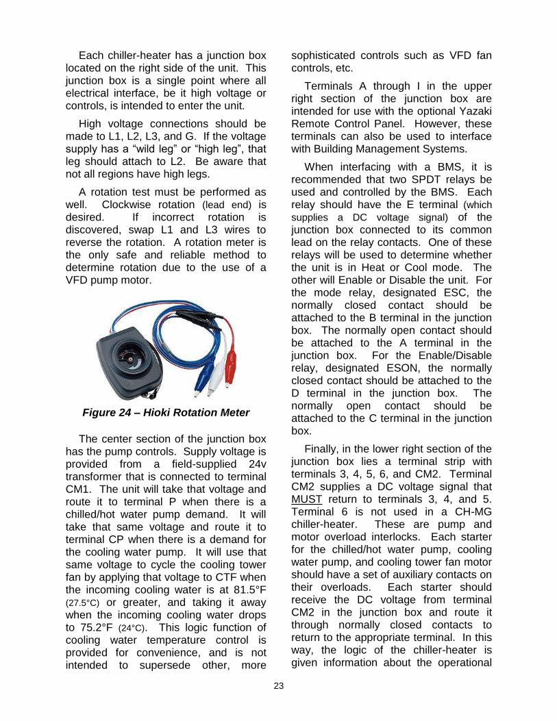
A rotation test must be performed as well. Clockwise rotation (lead end) is desired. If incorrect rotation is discovered, swap L1 and L3 wires to reverse the rotation. A rotation meter is the only safe and reliable method to determine rotation due to the use of a VFD pump motor.
Figure 24 – Hioki Rotation Meter
The center section of the junction box has the pump controls. Supply voltage is provided from a field-supplied 24v transformer that is connected to terminal CM1. The unit will take that voltage and route it to terminal P when there is a chilled/hot water pump demand. It will take that same voltage and route it to terminal CP when there is a demand for the cooling water pump. It will use that same voltage to cycle the cooling tower fan by applying that voltage to CTF when the incoming cooling water is at 81.5°F (27.5°C) or greater, and taking it away when the incoming cooling water drops to 75.2°F (24°C). This logic function of cooling water temperature control is provided for convenience, and is not intended to supersede other, more
sophisticated controls such as VFD fan controls, etc.
Terminals A through I in the upper right section of the junction box are intended for use with the optional Yazaki Remote Control Panel. However, these terminals can also be used to interface with Building Management Systems.
When interfacing with a BMS, it is recommended that two SPDT relays be used and controlled by the BMS. Each relay should have the E terminal (which
supplies a DC voltage signal) of the junction box connected to its common lead on the relay contacts. One of these relays will be used to determine whether the unit is in Heat or Cool mode. The other will Enable or Disable the unit. For the mode relay, designated ESC, the normally closed contact should be attached to the B terminal in the junction box. The normally open contact should be attached to the A terminal in the junction box. For the Enable/Disable relay, designated ESON, the normally closed contact should be attached to the D terminal in the junction box. The normally open contact should be attached to the C terminal in the junction box.
Finally, in the lower right section of the junction box lies a terminal strip with terminals 3, 4, 5, 6, and CM2. Terminal CM2 supplies a DC voltage signal that MUST return to terminals 3, 4, and 5. Terminal 6 is not used in a CH-MG chiller-heater. These are pump and motor overload interlocks. Each starter for the chilled/hot water pump, cooling water pump, and cooling tower fan motor should have a set of auxiliary contacts on their overloads. Each starter should receive the DC voltage from terminal CM2 in the junction box and route it through normally closed contacts to return to the appropriate terminal. In this way, the logic of the chiller-heater is given information about the operational

24
status of pumps or motor. Terminal 3 should receive the return signal from the chilled/hot water pump overload auxiliary contacts. Terminal 4 should receive the return signal from the cooling water pump overload auxiliary contacts.
Terminal 5 should receive the return signal from the cooling tower fan overload auxiliary contacts. If the return signal is not sensed, the unit will immediately generate an error code (E005, E006, and/or E007).
TYPICAL FIELD WIRING DIAGRAM

25
Figure 25 – Optional Remote Control Pad
26
WATER QUALITY
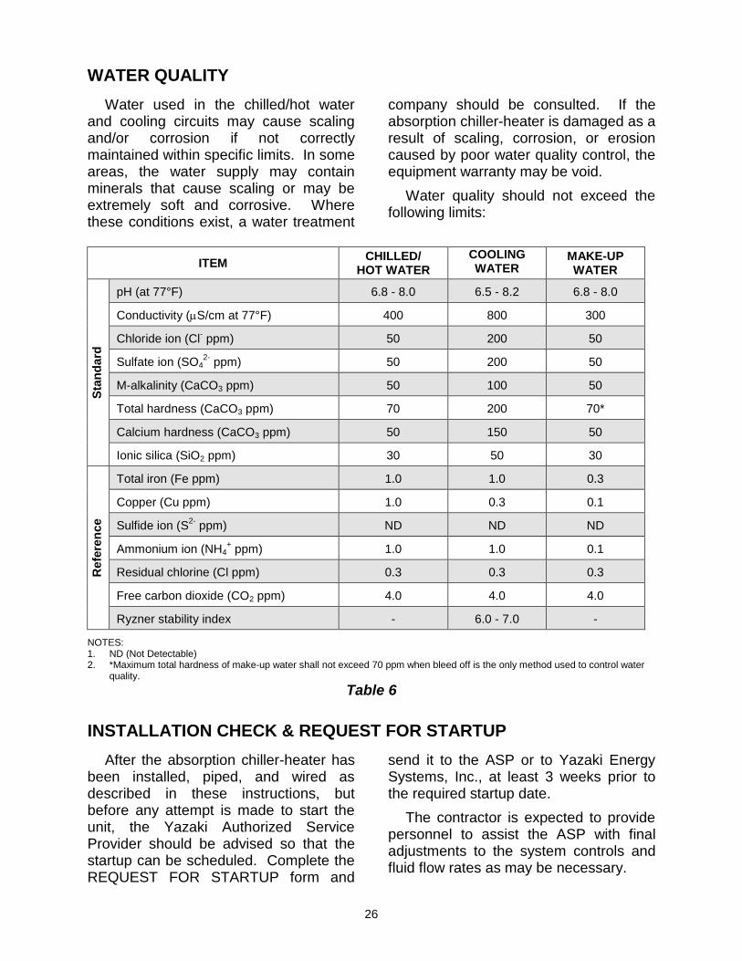
Water used in the chilled/hot water and cooling circuits may cause scaling and/or corrosion if not correctly maintained within specific limits. In some areas, the water supply may contain minerals that cause scaling or may be extremely soft and corrosive. Where these conditions exist, a water treatment
company should be consulted. If the absorption chiller-heater is damaged as a result of scaling, corrosion, or erosion caused by poor water quality control, the equipment warranty may be void.
Water quality should not exceed the following limits:
ITEM CHILLED/
HOT WATER
COOLING WATER
MAKE-UP WATER
Sta
nd
ard
pH (at 77°F) 6.8 - 8.0 6.5 - 8.2 6.8 - 8.0
Conductivity (S/cm at 77°F) 400 800 300
Chloride ion (Cl- ppm) 50 200 50
Sulfate ion (SO42-
ppm) 50 200 50
M-alkalinity (CaCO3 ppm) 50 100 50
Total hardness (CaCO3 ppm) 70 200 70*
Calcium hardness (CaCO3 ppm) 50 150 50
Ionic silica (SiO2 ppm) 30 50 30
Refe
ren
ce
Total iron (Fe ppm) 1.0 1.0 0.3
Copper (Cu ppm) 1.0 0.3 0.1
Sulfide ion (S2-
ppm) ND ND ND
Ammonium ion (NH4+ ppm) 1.0 1.0 0.1
Residual chlorine (Cl ppm) 0.3 0.3 0.3
Free carbon dioxide (CO2 ppm) 4.0 4.0 4.0
Ryzner stability index - 6.0 - 7.0 - NOTES: 1. ND (Not Detectable) 2. *Maximum total hardness of make-up water shall not exceed 70 ppm when bleed off is the only method used to control water
quality.
Table 6
INSTALLATION CHECK & REQUEST FOR STARTUP
After the absorption chiller-heater has been installed, piped, and wired as described in these instructions, but before any attempt is made to start the unit, the Yazaki Authorized Service Provider should be advised so that the startup can be scheduled. Complete the REQUEST FOR STARTUP form and
send it to the ASP or to Yazaki Energy Systems, Inc., at least 3 weeks prior to the required startup date.
The contractor is expected to provide personnel to assist the ASP with final adjustments to the system controls and fluid flow rates as may be necessary.

27
YAZAKI CH-MG SERIES CHILLER-HEATER
INSTALLATION CHECK AND REQUEST FOR START-UP
Yazaki Authorized Service Provider:
Address:
Project Name:
Project Address:
A. CHILLER-HEATER
1. Unit placed on foundation □
2. Unit leveled properly □
3. Service clearance provided on all
sides and top (40 in. front) □
4. Chiller-heater anchored by L-Anchor
plates to foundation (if required) □ *Anchors may be required by some state and local codes.
B. WATER PIPING
1. Chilled/hot water piping installed between chiller-heater, pumps and
air handling unit(s) □
2. Cooling water piping installed between chiller-heater, pumps, and
cooling tower □
3. Water piping leak tested and flushed □
4. System filled with water and glycol
(if required) and trapped air vented □
5. Flow setters installed in water piping □
6. Test plugs (Pete’s plugs) and/or thermowells installed in the inlet and
outlet piping of each chiller-heater □
7. Valves installed at each chiller-heater
for flow balancing and isolation □
8. Air vent valves installed on piping □
9. Strainers present and clean □
10. Expansion tank (properly charged) and water make-up piping installed to
chilled/hot water system □
11. Water make-up and fill lines installed
to the cooling tower □
12. Pressure relief valves, set at 113.8 psig (max.) installed on piping adjacent to
each chiller-heater (if required) □ C. GAS PIPING
1. Natural Gas supply is available to unit
between 7” wc and 10.5” wc □
2. Gas piping installation completed □
3. Gas cock and sediment trap installed □
4. Appliance regulator installed at each
chiller- heater (if required) □
5. Gas pipe leak tested and purged □
D. VENTING 1. Factory-provided vent cap installed
(outdoor installation) □
2. Barometric damper and Type-B vent extension installed on each chiller-
heater outlet (indoor installation) □
E. POWER WIRING 1. Power supply as indicated on the UNIT
NAMEPLATE, is connected □
2. Wiring completed between the chiller-heater, motor contactors and/or starters for the following : Chilled/hot water pump, cooling water pump and
cooling tower fan □
3. Rotation of each external pump and fan
motor checked □
4. Power supply wiring connected between a fused disconnect and each chiller-heater. (DO NOT operate
the chiller-heater) □
5. Power supply available near the
chiller-heater for a vacuum pump □ F. CONTROL WIRING
1. Motor contactors, starters, and/or manual controllers installed for all
external motors □
2. Control wiring installed between chiller-heater and pump/motor
contactors □
3. Interlock wiring installed between chiller-heater and thermal overloads on the following motors: Chilled/hot water pump, cooling water pump and
cooling tower fan □
G. CONDITIONS 1. Personnel available to assist with
start-up who are familiar with the system and have appropriate tools (adequate vacuum pump, combustion analyzer, vacuum gauge, proper hoses, etc.) □
Model No: Serial No:
Anticipated Startup Date:

28
YAZAKI AUTHORIZED SERVICE PROVIDER
For information concerning service, operation or technical assistance, please contact your
Yazaki Authorized Service Provider or the following:
YAZAKI ENERGY SYSTEMS, INC. 701 E PLANO PKWY, SUITE 305
PLANO, TEXAS 75074-6700
Phone: 469-229-5443 Fax: 469-229-5448
Email: [email protected] Web: www.yazakienergy.com
LISTED
This symbol on the product’s nameplate means it is listed by UNDERWRITERS LABORATORIES, INC.
Yazaki reserves the right to discontinue, or change at any time, specifications or designs without notice and without incurring obligations.
MGUL-II-1D1-0914