installation & maintenance instructions - … · bps range is complimented by ecosmart control...
TRANSCRIPT

10. 05. 18. Leaflet Number 671828nuaire.co.uk 029 2085 8200
Horizontal BPS with
INSTALLATION & MAINTENANCE INSTRUCTIONS
Control
2016ErP
COMPLIANTLEAKAGE
C L A S S
THER
MAL RIDGING
C L A SS
TB1
DEFLECTION
C L A S S
D1 FOR THE COMPLETE VENTLIATION SOULTION

nuaire.co.uk 029 2085 8200
BOXER BPS ECOSMART CONNECT CONTROL (CO)
The EMC Directive2014/30/EU
The Low Voltage Directive 2014/35/EU
XBOXER BPS VERTICAL MODELS
The information contained in this document provides details of installation, operation and maintenance for installers and users of the BPS packaged AHU units with heat recovery.
BOXER PACKAGED SOLUTION supply and extract unit range. Manufactured from Aluzinc corrosion resistant steel, with 50mm double skinned panels and anodized aluminium frame of a totally thermally-broken design, complying with the following specification in accordance with BS EN 1886: Mechanical strength, D1; Leakage class, L1; Thermal transmittance, T2; Thermal bridging, TB1.
BPS range has high efficiency centrifugal fans with EC motors. High efficiency thermal wheel or plate heat exchanger, Supply G4 pre-filter and F7 main filters as standard with M5 filtration of the extract air. BPS range includes optional heating (LPHW or Electric) and cooling (Chilled water, DX or Reverse Cycle). The Reverse Cycle coil is supplied as standard with Mitsubishi Mr Slim Condenser(s) and inbuilt PAC Control. Note: control wiring and piping by others, thermistor wiring (included). Installation must be carried out by F-Gas approvedinstaller.
A range of ancillaries include – attenuators, weather terminals, recirculation & frost modules.
BPS range is complimented by Ecosmart Control Platform which includes Basic, Classic, Connect & Adapt (Trend) as standard with a 5 year warranty.
General information regarding performance and specification for the equipment can be obtained from our technical literature, and/or project specific documen-tation.
CODE DESCRIPTION:B 8 15 H / L R / CO - L| | | | | | | |1 2 3 4 5 6 7 8
1. BOXER Package Solution Range
2. ERP year: 8 = 2018
3. Unit: 05, 10, 15 or 20
4. Heat Exchanger: H = Horizontal Plate
5. Heater: L = LPHW E = Electric N = No Heating
6. Cooling: R = Reverse Cycle** X = DX* C = Chilled Water N = No Cooling
7. Control type: AT = Ecosmart Adapt (Trend) CO = Ecosmart Connect ES = Ecosmart Classic BC = Basic control
8. Handing: L = Left, R = Right
*Condenser Unit and control by others.**Ecosmart Connect & Adapt models only.
1.0 INTRODUCTION
SUPPLY & EXTRACT VENTILATION UNITINSTALLATION & MAINTENANCE INSTRUCTIONS
Figure 1. Horizontal Plate Heat Exchanger unit.

10. 05. 18. Leaflet Number 671828
BOXER BPS ECOSMART CONNECT CONTROL (CO)
3
1.1 Ancillary Options (Based On Right Hand Version)
Quick Selection Guide BPS BOXER PACKAGED AHU’s - ANCILLARIES
BPS UnitModule
Part Number
Description
Attenuator
1B**AH/AR900-R BPS size **. Attenuator for Supply/Extract, Right Handed, for Horizontal PHX Units.
B**AH/AR900-L BPS size **. Attenuator for Supply/Extract, Left Handed, for Horizontal PHX Units.
Attenuator
1aB**AH/AA900-R BPS size **. Attenuator for Intake/Exhaust, Right Handed, for Horizontal PHX Units.
B**AH/AA900-L BPS size **. Attenuator for Intake/Exhaust, Right Handed, for Horizontal PHX Units.
Frost Coil - Electric
2B**AH/FE-R BPS size **. Frost Coil Electric, 36kW, Right Handed, for Horizontal PHX Units.
B**AH/FE-L BPS size **. Frost Coil Electric, 36kW, Left Handed, for Horizontal PHX Units.
Frost Coil - LPHW
3B**AH/FL-R BPS size **. Frost Coil LPHW, Right Handed, for Horizontal PHX Units.
B**AH/FL-L BPS size **. Frost Coil LPHW, Left Handed, for Horizontal PHX Units.
Recirculation Module
4B**AH/RM-R BPS size **. Recirculation Module, Right Handed, for Horizontal PHX Units.
B**AH/RM-L BPS size **. Recirculation Module, Left Handed, for Horizontal PHX Units.
Weather Terminal
5B**AH/RT BPS size **. Weather Terminal, for Horizontal PHX Units.
Inlet/Outlet Damper
6B**AH/D BPS size **. Inlet/Outlet Dampers suitable for right or left handed Horizontal PHX Units.
Weather Terminal & Inlet/Outlet Damper
7
B**AH/RTD-R BPS size **. Weather Terminal & Damper, Right Handed, for Horizontal PHX Units.
B**AH/RTD-L BPS size **. Weather Terminal & Damper, Left Handed, for Horizontal PHX Units.
** Insert one of the following for the relevant BPS unit.
1a
Plate HeatExchanger
Control Section
SupplyModule
Electric Heater
LPHW, DX or CHW
Filter
4
5 6
7
Extract Module
2 or 3
1
Filter
INTAKE / EXHAUST
SUPPLY / EXTRACT
Figure 2.

nuaire.co.uk 029 2085 8200
BOXER BPS ECOSMART CONNECT CONTROL (CO)
Nuaire intend that this manual and any other supportive documents that may be mentioned should be read and understood by authorised operating and service personnel before performing any task related to the installation, com-missioning and maintenance of Nuaire BPS Air handling units and any associated components.
The operative / service personnel should comply with good industry practice, the appropriate authority and conformance with all statutory and governing regulations.
The unit must be manually isolated from the electrical supply and a period of five minutes allowed to elapse before any access door is opened for the purpose of general maintenance.
Sharp edges need to be handled with caution; most of the air handling equip-ment will contain sharp edges on the internal and external surfaces. Care should be taken to ensure that all personnel are aware of this and precautions are implemented to ensure that no injuries are caused.
To help operating and service personnel perform tasks safely, please pay atten-tion to the notes throughout this document (see below for example).
All notes are designed to alert the reader to potential hazards.
IMPORTANTInformation contained in this format is designedto outline important Notes, Dangers, Cautions
and Warnings.
Please ensure that prior to commencing anyactivity, the following guide lines are adheredto:
• During installation, commissioning, operation and maintenance of an air handling unit, operatives may be exposed to hazards including, rotating components, refrigerants and high voltage electricity. If misused or handled improperly, each of these items has the potential to cause bodily injury or death.
• Identification and recognition of inherent hazards is the obligation of responsible personnel. They must protect themselves and others by proceeding with care and consideration to health and safety measures.
• All risk assessments have been carried out and are in place prior to carrying out any activity.
• The relevant protective equipment and attire is worn by each relevant member of staff.
• That the unit Nuaire have supplied meets the standards written in the technical specification.
• The necessary lifting gear and site plant is available to lift and position the unit in accordance to the technical drawings.
• All electrical equipment is connected and earthed in accordance with I.E.E. Regulations.
• The Plant is fully isolated from the mains supply and allowed to run down for a minimum of five to ten minutes before opening any access door prior to the commencement of any maintenance work.
• When maintenance work is finished, please ensure that the unit is left in a clean state, and all access doors /panels are fastened and locked correctly (Locked handle returned to holder).
• At no point should a unit be used for the storage of tools or working equipment.
IMPORTANTComponent parts are usually not fitted with safety guards
i.e. fan inlet. The casing of the unit acts as a protective guardfor all component parts.
2.0 HEALTH & SAFETY

10. 05. 18. Leaflet Number 671828
BOXER BPS ECOSMART CONNECT CONTROL (CO)
5
3.0 DELIVERY & RECEIPT OF EQUIPMENT
3.1 Off Loading And Handling From the Delivery Vehicle
All equipment is inspected prior to despatch and leaves the factory in good condition. Upon receipt of the equipment an inspection should be made and any damage indicated on the delivery note.
Particulars of damage and/or incomplete delivery should be endorsed by the driver delivering the goods before offloading by the purchaser.
No responsibility will be accepted for damage sustained during the offloading from the vehicle or on the site thereafter.
All claims for damage and/or incomplete delivery must be reported to Nuaire within two days of receipt of the equipment.
The weight of the unit modules and palletised items are displayed on the packaging.
Some of the modules have an uneven weight distribution, and this will be indicated by labelling where appropriate.
Offloading and positioning of the equipment is the responsibility of the purchaser. Items should only be lifted by competent personnel following appropriate risk assessment.
IMPORTANT
To ensure that the delivery vehicle is loaded according to the planned method of offloading,
Nuaire should be notified, to ensure coordination.NOTE: When offloading, care must be taken
to ensure that the AHU is kept level at all times.
IMPORTANT
To ensure that no roof damage occurs additional timber packaging must be used.
Palletised. Forklift. Assembly with base frame.
Slings via spreaders fitted tounit with base frame.
Please note that above images are examples of typical lifting methods.Actual unit lifting plan and risks must be assessed by competent personnel before moving the unit.
For Base Frame Lifting Points (see section 3.2)
Figure 3. Typical methods of lifting.
nuaire.co.uk 029 2085 8200
BOXER BPS ECOSMART CONNECT CONTROL (CO)
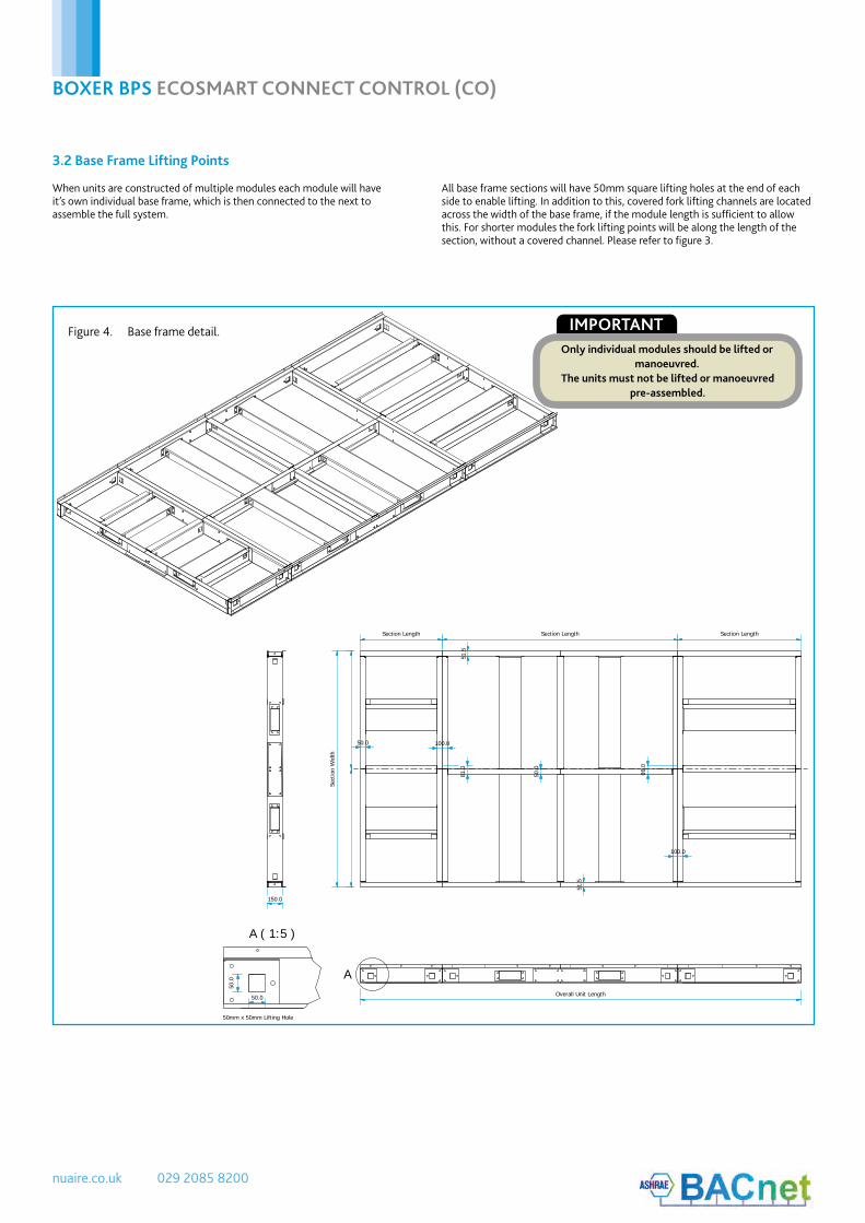
3.2 Base Frame Lifting Points
When units are constructed of multiple modules each module will have it’s own individual base frame, which is then connected to the next to assemble the full system.
All base frame sections will have 50mm square lifting holes at the end of each side to enable lifting. In addition to this, covered fork lifting channels are located across the width of the base frame, if the module length is sufficient to allow this. For shorter modules the fork lifting points will be along the length of the section, without a covered channel. Please refer to figure 3.
A
A ( 1:5 )
150.0
50.0
51.5
50.0
51.5
100.0
100.0
86.0
81.0
Overall Unit Length
Section Length Section Length Section Length
Sect
ion
Wid
th
50.0
50.0
50mm x 50mm Lifting Hole
IMPORTANTOnly individual modules should be lifted or
manoeuvred.The units must not be lifted or manoeuvred
pre-assembled.
Figure 4. Base frame detail.

10. 05. 18. Leaflet Number 671828
BOXER BPS ECOSMART CONNECT CONTROL (CO)
7
3.3 Unit Protection
4.2 Air Leakage
4.3 Unit Joints
3.4 Unit Storage
4.0 ERECTION & ASSEMBLY
4.1 Unit Location
Unless otherwise specified, unit sections will be delivered to site covered in “shrink wrap” polythene, which should provide a more than adequate level of protection against inclement weather.
Should alternative methods of unit protection be required (i.e. timber, Corex,
or flame retardant materials), Nuaire Limited should be notified of the specific requirements at the pre- contract stage. Waste must be disposed of by a registered waste carrier in accordance to national regulations.
Loading, transportation, off loading and site positioning can cause the air handling unit structures to move, therefore panel seals will not always remain fully intact.
It is inevitable that in such cases, re-sealing of the units panels and joints may have to be carried out on site for the air-handling units to achieve the required leakage classification.
Door locking mechanisms may also have to be adjusted.
Nuaire cannot be held responsible for the units failing a site leakagetest if the above have not been carried out correctly.
After unwrapping, temporarily remove the rubber weatherproof cover strip and M10 base frame bolts from any modules and store in a safe location for later use.
Apply the sealing gasket as necessary to the mating faces of the unit frames. Typically the sealing gaskets are pre-fitted to the heat exchanger module; ancillary modules will be provided with a roll of sealing gasket for on-site fitting.
Make the unit joints in the following order:•Left and right hand side M10 bolts between the modules’ base frames (See Figure 5).
•Left and right hand side M6 Lower 3 axis alignment clamps (see Figure 6).•Left and right hand side M6 Middle 3 axis alignment clamps.•Left and right hand side M6 Upper 3 axis alignment clamps.
Finally, where the roofs of the two sections meet, the rubber weatherproof cover strip removed earlier must be applied to seal the seam (see Figure 7).
Air leakage, air blow marks to the unit casings and unacceptable noise levels could result if the correct installation procedures are not employed.
The equipment must be stored in a dry, internal location. Ductwork connection apertures should be sealed against the ingress of dust, water and vermin. Note that units that are intended for external locations are generally not fully weatherproofed until their installation, including ductwork connections, is complete.
If the storage period is to exceed two months, contact Nuaire for guidance on the appropriate ‘mothballing’ procedures. Do not stack units, modules or components.
Installation must be carried out by competent personnel, in accordance with good industry practice, with the appropriate authority and in conformance with all statutory and governing regulations.
The unit should stand upright and level on the floor, foundation or supporting steelwork which should be rigid, flat and level and should be capable of supporting the weight of the unit including water or refrigerant in the coils.
Nuaire Limited takes no responsibility for the coordination of support.
To prevent possible reintroduction of contaminated air through the outside air intake, the unit should be located away from building flue stacks or exhaust ventilators.
Once assembled and in position, sufficient free space must be available adjacent to the unit for future inspection, maintenance, component service, repair and replacement and connection of services.
It is recommended that at least half the unit width (horizontally arranged units) + 100mm be allowed. A minimum of 600mm is required for regular maintenance.
Motors are fitted with ‘sealed for life’ bearings and do not require any lubrication. All dampers should be rotated and lubricated as necessary.
3.5 Lubrication
IMPORTANTSufficient clearance for U-traps on condensate drain andoverflow connections should also be considered by the
purchaser.
IMPORTANT
Prior to making the unit joints, you must ensure the base frames of adjoining modules are contiguous (fully touching) along the width of the unit. Failure to do so can result in deformation of the unit frame
when using the three axis alignment clamps.
Figure 5. M10 base frame bolt.
Figure 6. Three axis alignment clamp.

nuaire.co.uk 029 2085 8200
BOXER BPS ECOSMART CONNECT CONTROL (CO)
4.6 Weather Resistant Units
4.7 Connections
Weather resistant units in multiple sections will have sectional roof components that must be fitted and sealed after the unit sections are bolted together. All necessary nuts, bolts, washers and sealant are supplied with each unit and are normally bagged and located within the fan section. Suitable mastic sealant is to be provided by others.
The equipment must not be exposed to the weather in an unassembled or partially assembled state. All ductwork, sealing and assembly work must be completed before the unit can be considered weather resistant.Where the weatherproof roof assembly of two sections meet, a rubber weatherproof cover strip must be applied to seal the seam, this will be supplied with the unit.
Nuaire do not provide ductwork connections with units, instead the open ended framework should be utilised. Spigots are available as an option, refer to technical documents for information relating specifically to the manufactured unit.
4.7.1 Ductwork
4.4 Condensate Drain
4.5 Thermal Wheel Transport Packaging
Plate heat exchanger components and modules that incorporate cooling coils may produce condensation during use. An insulated drip tray and condensate pump is provided where necessary. The drain connection must be connected to a suitable drainage point.
Condensate pump specification
Maximum flow rate = 50 L/H
Maximum head = 20m Vertical, 100m Horizontal
Pipe Connection size (Low Pressure Condensate connection) = 8 mm
Please note: Thermal wheel transport packing blocks must be removed prior to operation of the thermal wheel module.
IMPORTANTIf a frost coil is not fitted then appropriate control methods
must be taken to prevent the coils, filters and otherequipment from freezing (by others).
When connecting coils, special care is needed to allow for expansion and contractions. Prior to any equalising connection, ensure that the thermostatic expansion valve for the DX coil is securely fitted.
Each coil section should be trapped and special care should be taken to ensure that there are no vertical rising condense lines, unless pumped.
Wet pipe connections sizes are listed in the table below.
When constant pressure mode control is to be used, constant pressure extract fans are supplied to control the static pressure at the fan inlet. This standard unit set up is suitable for the majority of applications. However, when high pressure ancillaries are fitted to the fan’s inlet side, the low pressure tapping must be moved from the fan chamber, to a location upstream of the ancillaries.
Failure to do this will result in excessive pressure being applied to the dampers at the rooms when the system is running in trickle mode.
4.7.2 Coils
4.7.3 Constant Pressure
Unit Size
Frost Coil (LPHW)
Heating Coil (LPHW)
Cooling Coil (CHW)
Flow Return Flow Return Flow Return
05 15 mm 15 mm 15 mm 15 mm 22 mm 22 mm
10 22 mm 22 mm 22 mm 22 mm 22 mm 22 mm
15 22 mm 22 mm 22 mm 22 mm 28 mm 28 mm
20 28 mm 28 mm 28 mm 28 mm 35 mm 35 mm
Figure 7. Roof seal.
10. 05. 18. Leaflet Number 671828
BOXER BPS ECOSMART CONNECT CONTROL (CO)
9
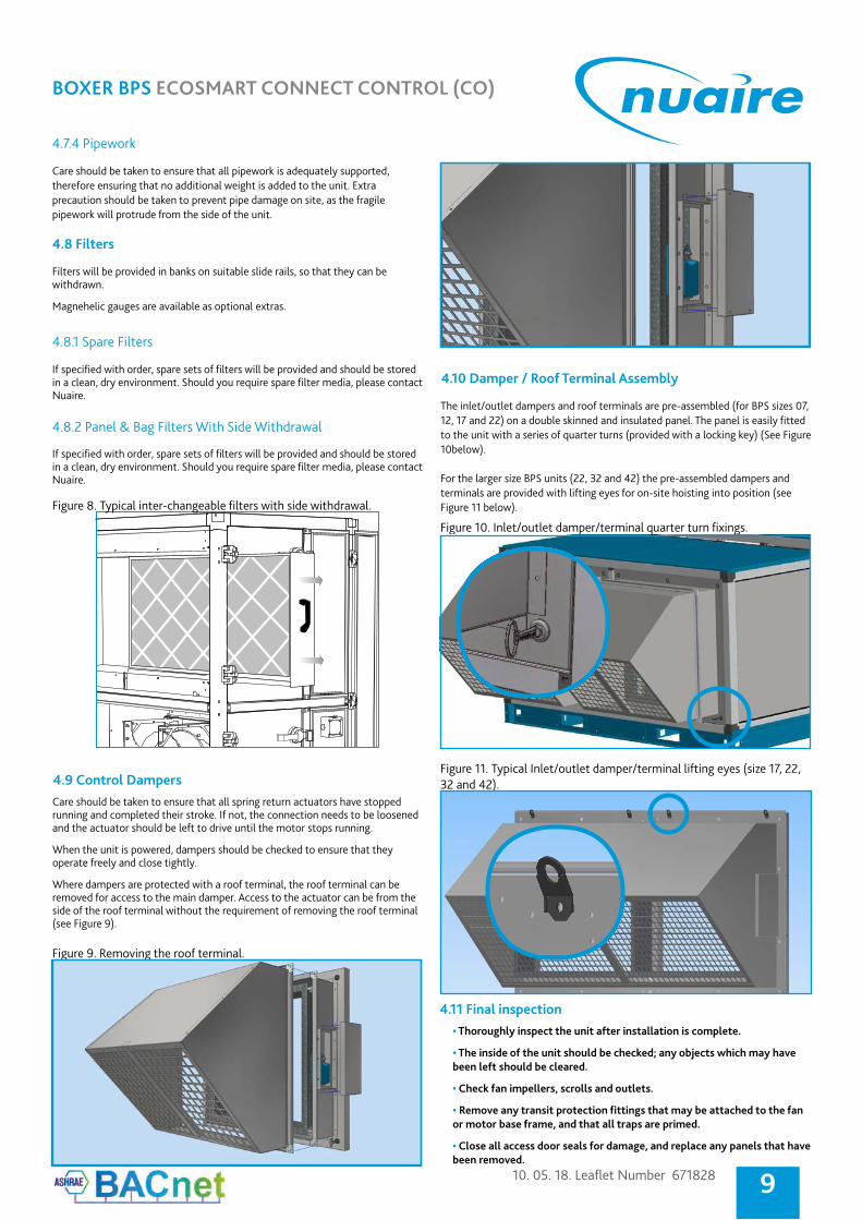
Care should be taken to ensure that all pipework is adequately supported, therefore ensuring that no additional weight is added to the unit. Extra precaution should be taken to prevent pipe damage on site, as the fragile pipework will protrude from the side of the unit.
4.7.4 Pipework
4.8 Filters
4.8.1 Spare Filters
4.8.2 Panel & Bag Filters With Side Withdrawal
Filters will be provided in banks on suitable slide rails, so that they can be withdrawn.
Magnehelic gauges are available as optional extras.
If specified with order, spare sets of filters will be provided and should be stored in a clean, dry environment. Should you require spare filter media, please contact Nuaire.
If specified with order, spare sets of filters will be provided and should be stored in a clean, dry environment. Should you require spare filter media, please contact Nuaire.
Figure 8. Typical inter-changeable filters with side withdrawal.
4.11 Final inspection
4.9 Control Dampers
The inlet/outlet dampers and roof terminals are pre-assembled (for BPS sizes 07, 12, 17 and 22) on a double skinned and insulated panel. The panel is easily fitted to the unit with a series of quarter turns (provided with a locking key) (See Figure 10below).
For the larger size BPS units (22, 32 and 42) the pre-assembled dampers and terminals are provided with lifting eyes for on-site hoisting into position (see Figure 11 below).
• Thoroughly inspect the unit after installation is complete.
• The inside of the unit should be checked; any objects which may have been left should be cleared.
• Check fan impellers, scrolls and outlets.
• Remove any transit protection fittings that may be attached to the fan or motor base frame, and that all traps are primed.
• Close all access door seals for damage, and replace any panels that have been removed.
Care should be taken to ensure that all spring return actuators have stopped running and completed their stroke. If not, the connection needs to be loosened and the actuator should be left to drive until the motor stops running.
When the unit is powered, dampers should be checked to ensure that they operate freely and close tightly.
Where dampers are protected with a roof terminal, the roof terminal can be removed for access to the main damper. Access to the actuator can be from the side of the roof terminal without the requirement of removing the roof terminal (see Figure 9).
Figure 9. Removing the roof terminal.
4.10 Damper / Roof Terminal Assembly
Figure 10. Inlet/outlet damper/terminal quarter turn fixings.
Figure 11. Typical Inlet/outlet damper/terminal lifting eyes (size 17, 22, 32 and 42).
nuaire.co.uk 029 2085 8200
BOXER BPS ECOSMART CONNECT CONTROL (CO)
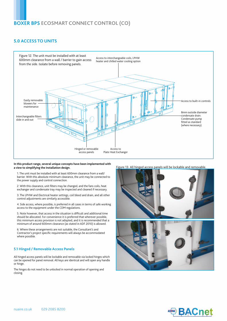
Easily removable blowers for maintenance
Access to built-in controls
Interchangeable filters slide in and out
Hinged or removable access panels
Access to Plate Heat Exchanger
Access to interchangeable coils, LPHW heater and chilled water cooling option
8mm outside diameter condensate drain. Condensate pump fitted as standard (where necessary).
5.0 ACCESS TO UNITS
5.1 Hinged / Removable Access Panels
Figure 12. The unit must be installed with at least 600mm clearance from a wall / barrier to gain access from the side. Isolate before removing panels.
In this product range, several unique concepts have been implemented with a view to simplifying the installation design.
1. The unit must be installed with at least 600mm clearance from a wall/barrier. With this absolute minimum clearance, the unit may be connected to the power supply and control connection.
2. With this clearance, unit filters may be changed, and the fans coils, heat exchanger and condensate tray may be inspected and cleaned if necessary.
3. The LPHW and Electrical heater settings, coil bleed and drain, and all other control adjustments are similarly accessible.
4. Side access, where possible, is preferred in all cases in terms of safe working access to the equipment under the CDM regulations.
5. Note however, that access in the situation is difficult and additional time should be allocated. For convenience it is preferred that wherever possible, this minimum access provision is not adopted, and it is recommended that a minimum of around 600mm clearance (as stated in ADF 2010) is allowed.
6. Where these arrangements are not suitable, the Consultant’s and Contractor’s project specific requirements will always be accommodated where possible.
All hinged access panels will be lockable and removable via locked hinges which can be opened for panel removal. All keys are identical and will open any handle or hinge.
The hinges do not need to be unlocked in normal operation of opening and closing.
Figure 13. All hinged access panels will be lockable and removable.

10. 05. 18. Leaflet Number 671828
BOXER BPS ECOSMART CONNECT CONTROL (CO)
11
IntakeExhaust
ExtractSupply
Model shown is left handed
ExtractSupply
Intake
ExhaustModel shown is right handed
Figure 14. Access for horizontal plate heat exchanger units (Right and Left handed).
EXTRACT
SUPPLY
INTAKE
DISCHARGE
Access
Shown from top (Left hand - L).
Access
CONTROLS
LPHW
600mm
600mm
EXTRACT
SUPPLY
INTAKE
DISCHARGE
Access
Shown from top (Right hand - R).
Access600mm
600mm

nuaire.co.uk 029 2085 8200
BOXER BPS ECOSMART CONNECT CONTROL (CO)
6.0 INTERNAL CONNECTIONSThere are a number of internal connections that need to be completed prior to starting/commissioning the unit. These consist of all the wiring connections and the condensate hose (plate heat exchanger option only).
Please ensure that the condensate hose is connected between modules. Care must be taken to ensure a constant fall in gradient is maintained and the hose is kept taught (see Figure 15).
Access is available in the fan plate to allow electrical/wiring connections to be made between modules (see Figure 16). When making the wiring connections, the sensor loop (see Figure 17) must be removed and relocated to the end of the unit.
Figure 15. Condensate hose detail.
Figure 16. Fan Plate access door.
Figure 17. Sensor loop detail.
10. 05. 18. Leaflet Number 671828
BOXER BPS ECOSMART CONNECT CONTROL (CO)
13
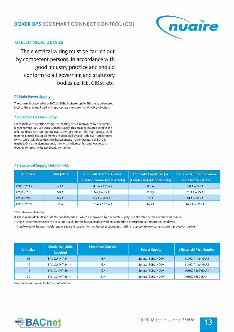
7.0 ELECTRICAL DETAILS
The electrical wiring must be carried out by competent persons, in accordance with
good industry practice and shouldconform to all governing and statutory
bodies i.e. IEE, CIBSE etc.
7.1 Main Power Supply
7.2 Electric Heater Supply
The control is powered by a 400Vac 50Hz 3 phase supply. This must be isolated local to the unit and fitted with appropriate overcurrent and fault protection.
For models with electric heating, the heating circuit is powered by a separate, higher current, 400Vac 50Hz 3 phase supply. This must be isolated local to the unit and fitted with appropriate overcurrent protection. The main supply is still required.Electric heater elements are protected by a fail-safe over-temperature switch which will disconnect the heater supply if a temperature of 80°C is reached. Once the elements cool, the switch will reset but a power cycle is required to reset the heater supply contactor.
* Denotes any character.
# These values do NOT include the condenser units, which are powered by a separate supply. See the table below or condenser manual.
† Single heater models require a separate supply for the heater section, with an appropriate overcurrent current protection device.
‡ Double electric heater models require separate supplies for two heater sections, each with an appropriate overcurrent current protection device.
Unit SizeCondenser Units
Required
Maximum Current Power Supply Mitsubishi Part Number
05 BPS-CU-MIT-14 x1 13A 3phase, 50Hz, 400V PUHZ-P140YHAR2
10 BPS-CU-MIT-14 x1 13A 3phase, 50Hz, 400V PUHZ-P140YHAR2
15 BPS-CU-MIT-20 x1 19A 3phase, 50Hz, 400V PUHZ-P200YKAR1
20 BPS-CU-MIT-25 x1 21A 3phase, 50Hz, 400V PUHZ-P250YKAR1
See condenser manual for further information.
7.3 Electrical Supply Details - FLC
Unit Size Unit (FLC) Unit with Electric Heater
(Electric Heater Models Only)
Unit with Condenser(s)
(Condenser(s) Models only)
Units with both Condenser
and Electric Heater
B*05H/**AS 4.3 A 4.3 A + 17.5 A † 8.8 A 8.8 A + 17.5 A †
B*10H/**ES 6.8 A 6.8 A + 35 A † 11.3 A 11.3 A + 35 A †
B*15H/**ES 9.5 A 9.5 A + 52.5 A † 14 A 14 A + 52.5 A †
B*20H/**ES 10 A 10 A + 52.5 A † 14.5 A 14.5 A + 52.5 A †
nuaire.co.uk 029 2085 8200
BOXER BPS ECOSMART CONNECT CONTROL (CO)
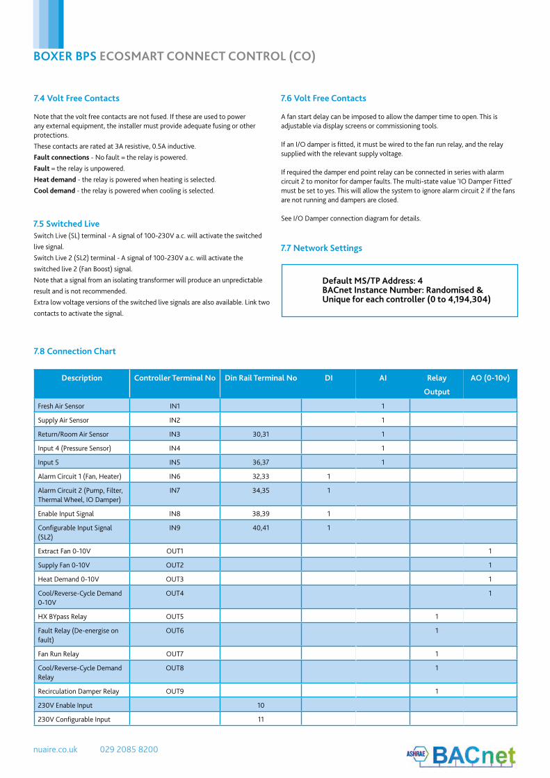
Description Controller Terminal No Din Rail Terminal No DI AI Relay
Output
AO (0-10v)
Fresh Air Sensor IN1 1
Supply Air Sensor IN2 1
Return/Room Air Sensor IN3 30,31 1
Input 4 (Pressure Sensor) IN4 1
Input 5 IN5 36,37 1
Alarm Circuit 1 (Fan, Heater) IN6 32,33 1
Alarm Circuit 2 (Pump, Filter, Thermal Wheel, IO Damper)
IN7 34,35 1
Enable Input Signal IN8 38,39 1
Configurable Input Signal (SL2)
IN9 40,41 1
Extract Fan 0-10V OUT1 1
Supply Fan 0-10V OUT2 1
Heat Demand 0-10V OUT3 1
Cool/Reverse-Cycle Demand 0-10V
OUT4 1
HX BYpass Relay OUT5 1
Fault Relay (De-energise on fault)
OUT6 1
Fan Run Relay OUT7 1
Cool/Reverse-Cycle Demand Relay
OUT8 1
Recirculation Damper Relay OUT9 1
230V Enable Input 10
230V Configurable Input 11
7.8 Connection Chart
Note that the volt free contacts are not fused. If these are used to power any external equipment, the installer must provide adequate fusing or other protections.
These contacts are rated at 3A resistive, 0.5A inductive.
Fault connections - No fault = the relay is powered.
Fault = the relay is unpowered.
Heat demand - the relay is powered when heating is selected.
Cool demand - the relay is powered when cooling is selected.
A fan start delay can be imposed to allow the damper time to open. This is adjustable via display screens or commissioning tools.
If an I/O damper is fitted, it must be wired to the fan run relay, and the relay supplied with the relevant supply voltage.
If required the damper end point relay can be connected in series with alarm circuit 2 to monitor for damper faults. The multi-state value ‘IO Damper Fitted’ must be set to yes. This will allow the system to ignore alarm circuit 2 if the fans are not running and dampers are closed.
See I/O Damper connection diagram for details.
Switch Live (SL) terminal - A signal of 100-230V a.c. will activate the switched
live signal.
Switch Live 2 (SL2) terminal - A signal of 100-230V a.c. will activate the
switched live 2 (Fan Boost) signal.
Note that a signal from an isolating transformer will produce an unpredictable
result and is not recommended.
Extra low voltage versions of the switched live signals are also available. Link two
contacts to activate the signal.
7.4 Volt Free Contacts 7.6 Volt Free Contacts
7.5 Switched Live
7.7 Network Settings
Default MS/TP Address: 4BACnet Instance Number: Randomised & Unique for each controller (0 to 4,194,304)
10. 05. 18. Leaflet Number 671828
BOXER BPS ECOSMART CONNECT CONTROL (CO)
15
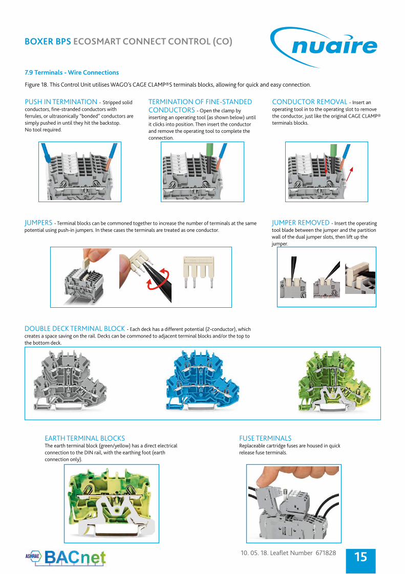
7.9 Terminals - Wire Connections
PUSH IN TERMINATION - Stripped solidconductors, fine-stranded conductors with ferrules, or ultrasonically “bonded” conductors are simply pushed in until they hit the backstop.No tool required.
CONDUCTOR REMOVAL - Insert an operating tool in to the operating slot to remove the conductor, just like the original CAGE CLAMP® terminals blocks.
JUMPER REMOVED - Insert the operating tool blade between the jumper and the partition wall of the dual jumper slots, then lift up the jumper.
FUSE TERMINALS Replaceable cartridge fuses are housed in quick release fuse terminals.
EARTH TERMINAL BLOCKS The earth terminal block (green/yellow) has a direct electrical connection to the DIN rail, with the earthing foot (earth connection only).
TERMINATION OF FINE-STANDED CONDUCTORS - Open the clamp by inserting an operating tool (as shown below) until it clicks into position. Then insert the conductor and remove the operating tool to complete the connection.
Figure 18. This Control Unit utilises WAGO’s CAGE CLAMP®S terminals blocks, allowing for quick and easy connection.
JUMPERS - Terminal blocks can be commoned together to increase the number of terminals at the same potential using push-in jumpers. In these cases the terminals are treated as one conductor.
DOUBLE DECK TERMINAL BLOCK - Each deck has a different potential (2-conductor), which creates a space saving on the rail. Decks can be commoned to adjacent terminal blocks and/or the top to the bottom deck.

nuaire.co.uk 029 2085 8200
BOXER BPS ECOSMART CONNECT CONTROL (CO)
7.10 Wiring - Isolator Wiring Point
Figure 19. Main wiring points for the customer is to the isolators situated on the sides of the units as shown below. Note: Cable glands for additional ancillary cabling.
ISOLATOR POSITIONED ON ELECTRIC HEATER UNIT
Unit Isolator
PLATE HEAT EXCHANGER UNIT
Cable glands situated on the sides of the units
10. 05. 18. Leaflet Number 671828
BOXER BPS ECOSMART CONNECT CONTROL (CO)
17
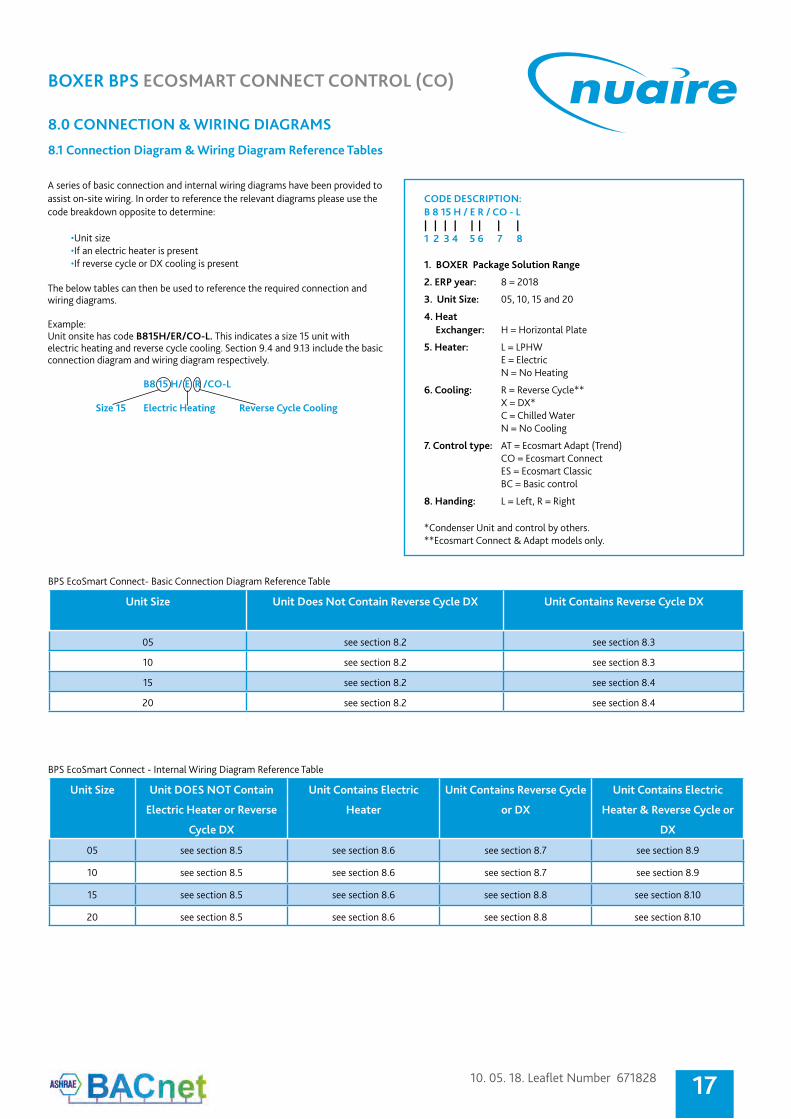
8.0 CONNECTION & WIRING DIAGRAMS
8.1 Connection Diagram & Wiring Diagram Reference Tables
CODE DESCRIPTION:B 8 15 H / E R / CO - L| | | | | | | |1 2 3 4 5 6 7 8
1. BOXER Package Solution Range
2. ERP year: 8 = 2018
3. Unit Size: 05, 10, 15 and 20
4. Heat Exchanger: H = Horizontal Plate
5. Heater: L = LPHW E = Electric N = No Heating
6. Cooling: R = Reverse Cycle** X = DX* C = Chilled Water N = No Cooling
7. Control type: AT = Ecosmart Adapt (Trend) CO = Ecosmart Connect ES = Ecosmart Classic BC = Basic control
8. Handing: L = Left, R = Right
*Condenser Unit and control by others.**Ecosmart Connect & Adapt models only.
A series of basic connection and internal wiring diagrams have been provided to assist on-site wiring. In order to reference the relevant diagrams please use the code breakdown opposite to determine:
•Unit size•If an electric heater is present•If reverse cycle or DX cooling is present
The below tables can then be used to reference the required connection and wiring diagrams. Example: Unit onsite has code B815H/ER/CO-L. This indicates a size 15 unit with electric heating and reverse cycle cooling. Section 9.4 and 9.13 include the basic connection diagram and wiring diagram respectively.
B8 15 H/ E R /CO-L Size 15 Electric Heating Reverse Cycle Cooling
BPS EcoSmart Connect - Internal Wiring Diagram Reference Table
BPS EcoSmart Connect- Basic Connection Diagram Reference Table
Cable glands situated on the sides of the units
Unit Size Unit Does Not Contain Reverse Cycle DX Unit Contains Reverse Cycle DX
05 see section 8.2 see section 8.3
10 see section 8.2 see section 8.3
15 see section 8.2 see section 8.4
20 see section 8.2 see section 8.4
Unit Size Unit DOES NOT Contain
Electric Heater or Reverse
Cycle DX
Unit Contains Electric
Heater
Unit Contains Reverse Cycle
or DX
Unit Contains Electric
Heater & Reverse Cycle or
DX
05 see section 8.5 see section 8.6 see section 8.7 see section 8.9
10 see section 8.5 see section 8.6 see section 8.7 see section 8.9
15 see section 8.5 see section 8.6 see section 8.8 see section 8.10
20 see section 8.5 see section 8.6 see section 8.8 see section 8.10

nuaire.co.uk 029 2085 8200
BOXER BPS ECOSMART CONNECT CONTROL (CO)
8.2 Basic Connection Diagram - BPS Sizes 05, 10, 15 & 20 (No Condenser Control)
F:\E
ngin
eerin
g\Pr
ojec
ts\P
roje
ct D
ata\
Plat
inum
\I&M
s\Ec
oSm
art C
onne
ct\D
raw
ings
\Con
nect
Con
nect
ion
Dia
gram
s\Co
nnec
t Con
nect
ion
Dia
gram
s.dw
g, 0
7/11
/201
7 09
:45:
25, A
utoC
AD P
DF
(Sm
alle
st F
ile).p
c3
Figure 20.
10. 05. 18. Leaflet Number 671828
BOXER BPS ECOSMART CONNECT CONTROL (CO)
19
F:\E
ngin
eerin
g\Pr
ojec
ts\P
roje
ct D
ata\
Plat
inum
\I&M
s\Ec
oSm
art C
onne
ct\D
raw
ings
\Con
nect
Con
nect
ion
Dia
gram
s\Co
nnec
t Con
nect
ion
Dia
gram
s.dw
g, 0
7/11
/201
7 09
:45:
25, A
utoC
AD P
DF
(Sm
alle
st F
ile).p
c3
nuaire.co.uk 029 2085 8200
BOXER BPS ECOSMART CONNECT CONTROL (CO)
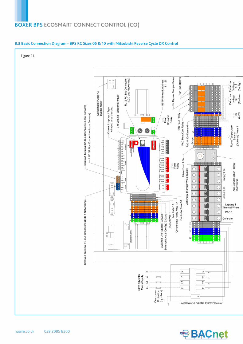
8.3 Basic Connection Diagram - BPS RC Sizes 05 & 10 with Mitsubishi Reverse Cycle DX Control
F:\E
ngin
eerin
g\Pr
ojec
ts\P
roje
ct D
ata\
Plat
inum
\I&M
s\Ec
oSm
art C
onne
ct\D
raw
ings
\Con
nect
Con
nect
ion
Dia
gram
s\Co
nnec
t Con
nect
ion
Dia
gram
s.dw
g, 0
7/11
/201
7 09
:45:
42, A
utoC
AD P
DF
(Sm
alle
st F
ile).p
c3
Figure 21.

10. 05. 18. Leaflet Number 671828
BOXER BPS ECOSMART CONNECT CONTROL (CO)
21
F:\E
ngin
eerin
g\Pr
ojec
ts\P
roje
ct D
ata\
Plat
inum
\I&M
s\Ec
oSm
art C
onne
ct\D
raw
ings
\Con
nect
Con
nect
ion
Dia
gram
s\Co
nnec
t Con
nect
ion
Dia
gram
s.dw
g, 0
7/11
/201
7 09
:45:
42, A
utoC
AD P
DF
(Sm
alle
st F
ile).p
c3
nuaire.co.uk 029 2085 8200
BOXER BPS ECOSMART CONNECT CONTROL (CO)
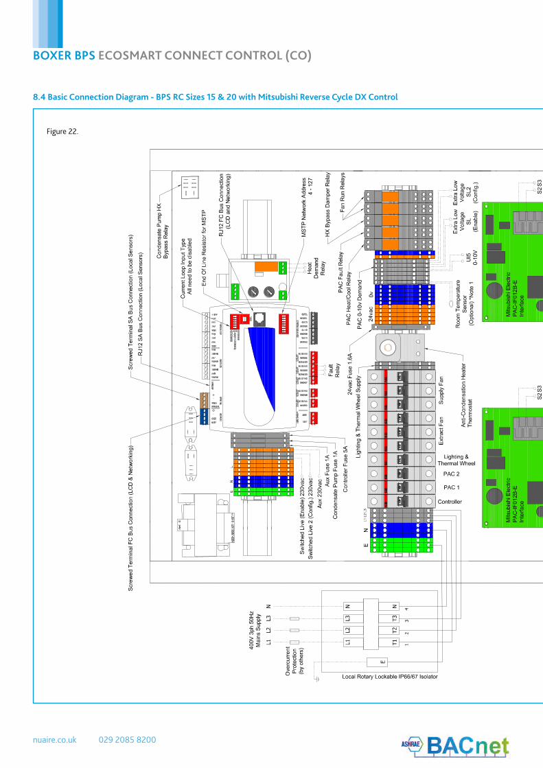
8.4 Basic Connection Diagram - BPS RC Sizes 15 & 20 with Mitsubishi Reverse Cycle DX Control
F:\E
ngin
eerin
g\Pr
ojec
ts\P
roje
ct D
ata\
Plat
inum
\I&M
s\Ec
oSm
art C
onne
ct\D
raw
ings
\Con
nect
Con
nect
ion
Dia
gram
s\Co
nnec
t Con
nect
ion
Dia
gram
s.dw
g, 0
7/11
/201
7 09
:45:
43, A
utoC
AD P
DF
(Sm
alle
st F
ile).p
c3
Figure 22.

10. 05. 18. Leaflet Number 671828
BOXER BPS ECOSMART CONNECT CONTROL (CO)
23
F:\E
ngin
eerin
g\Pr
ojec
ts\P
roje
ct D
ata\
Plat
inum
\I&M
s\Ec
oSm
art C
onne
ct\D
raw
ings
\Con
nect
Con
nect
ion
Dia
gram
s\Co
nnec
t Con
nect
ion
Dia
gram
s.dw
g, 0
7/11
/201
7 09
:45:
43, A
utoC
AD P
DF
(Sm
alle
st F
ile).p
c3

nuaire.co.uk 029 2085 8200
BOXER BPS ECOSMART CONNECT CONTROL (CO)
F:\Engineering\Projects\Project Data\Platinum\I&Ms\EcoSmart Connect\Drawings\Connect Control Schematics\Connect Control Diagrams.dwg, 07/11/2017 09:42:45, AutoCAD PDF (Smallest File).pc3
8.5.1 BPS Internal Wiring - Sizes 05 - 20 No Heating (or LPHW) (Sheet 1)
8.5 BPS Internal Wiring - Sizes 05 - 20 No Heating (or LPHW)
Figure 23.

10. 05. 18. Leaflet Number 671828
BOXER BPS ECOSMART CONNECT CONTROL (CO)
25F:\Engineering\Projects\Project Data\Platinum\I&Ms\EcoSmart Connect\Drawings\Connect Control Schematics\Connect Control Diagrams.dwg, 07/11/2017 09:42:45, AutoCAD PDF (Smallest File).pc3
nuaire.co.uk 029 2085 8200
BOXER BPS ECOSMART CONNECT CONTROL (CO)
F:\Engineering\Projects\Project Data\Platinum\I&Ms\EcoSmart Connect\Drawings\Connect Control Schematics\Connect Control Diagrams.dwg, 07/11/2017 09:42:47, AutoCAD PDF (Smallest File).pc3
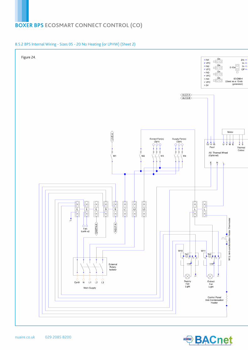
8.5.2 BPS Internal Wiring - Sizes 05 - 20 No Heating (or LPHW) (Sheet 2)
Figure 24.

10. 05. 18. Leaflet Number 671828
BOXER BPS ECOSMART CONNECT CONTROL (CO)
27F:\Engineering\Projects\Project Data\Platinum\I&Ms\EcoSmart Connect\Drawings\Connect Control Schematics\Connect Control Diagrams.dwg, 07/11/2017 09:42:47, AutoCAD PDF (Smallest File).pc3
nuaire.co.uk 029 2085 8200
BOXER BPS ECOSMART CONNECT CONTROL (CO)
F:\Engineering\Projects\Project Data\Platinum\I&Ms\EcoSmart Connect\Drawings\Connect Control Schematics\Connect Control Diagrams.dwg, 07/11/2017 09:42:49, AutoCAD PDF (Smallest File).pc3
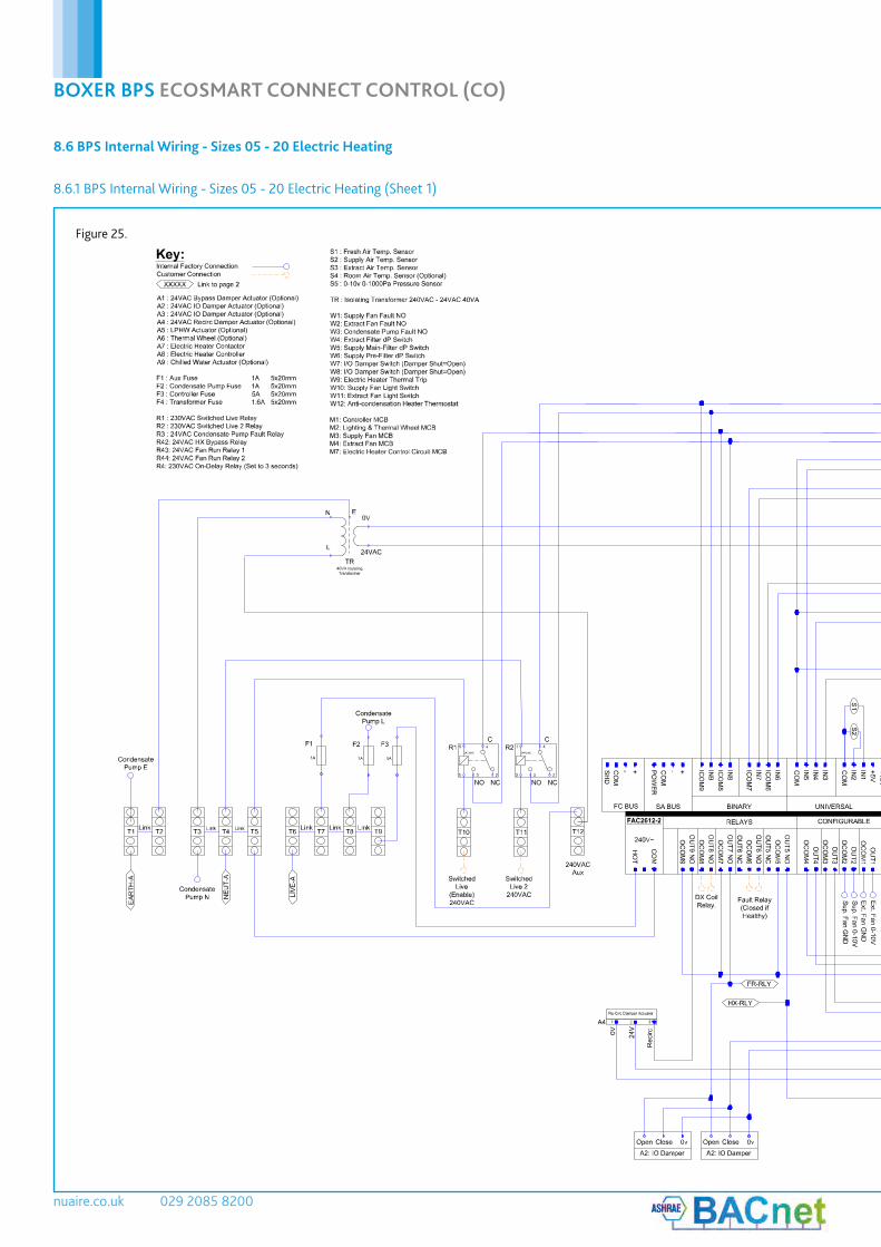
8.6 BPS Internal Wiring - Sizes 05 - 20 Electric Heating
8.6.1 BPS Internal Wiring - Sizes 05 - 20 Electric Heating (Sheet 1)
Figure 25.

10. 05. 18. Leaflet Number 671828
BOXER BPS ECOSMART CONNECT CONTROL (CO)
29F:\Engineering\Projects\Project Data\Platinum\I&Ms\EcoSmart Connect\Drawings\Connect Control Schematics\Connect Control Diagrams.dwg, 07/11/2017 09:42:49, AutoCAD PDF (Smallest File).pc3

nuaire.co.uk 029 2085 8200
BOXER BPS ECOSMART CONNECT CONTROL (CO)
F:\Engineering\Projects\Project Data\Platinum\I&Ms\EcoSmart Connect\Drawings\Connect Control Schematics\Connect Control Diagrams.dwg, 07/11/2017 09:42:51, AutoCAD PDF (Smallest File).pc3
8.6.2 BPS Internal Wiring - Sizes 05 - 20 Electric Heating (Sheet 2)
Figure 26.
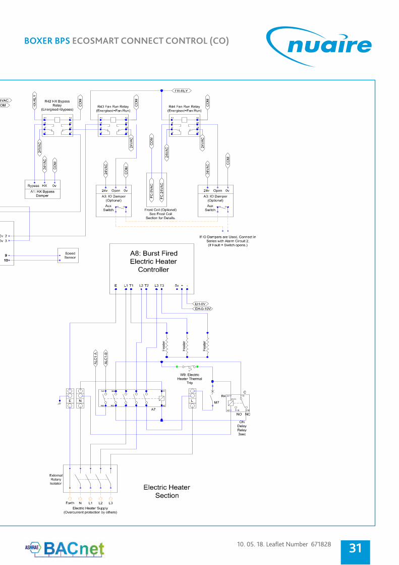
10. 05. 18. Leaflet Number 671828
BOXER BPS ECOSMART CONNECT CONTROL (CO)
31F:\Engineering\Projects\Project Data\Platinum\I&Ms\EcoSmart Connect\Drawings\Connect Control Schematics\Connect Control Diagrams.dwg, 07/11/2017 09:42:51, AutoCAD PDF (Smallest File).pc3
nuaire.co.uk 029 2085 8200
BOXER BPS ECOSMART CONNECT CONTROL (CO)
F:\Engineering\Projects\Project Data\Platinum\I&Ms\EcoSmart Connect\Drawings\Connect Control Schematics\Connect Control Diagrams.dwg, 07/11/2017 09:42:55, AutoCAD PDF (Smallest File).pc3
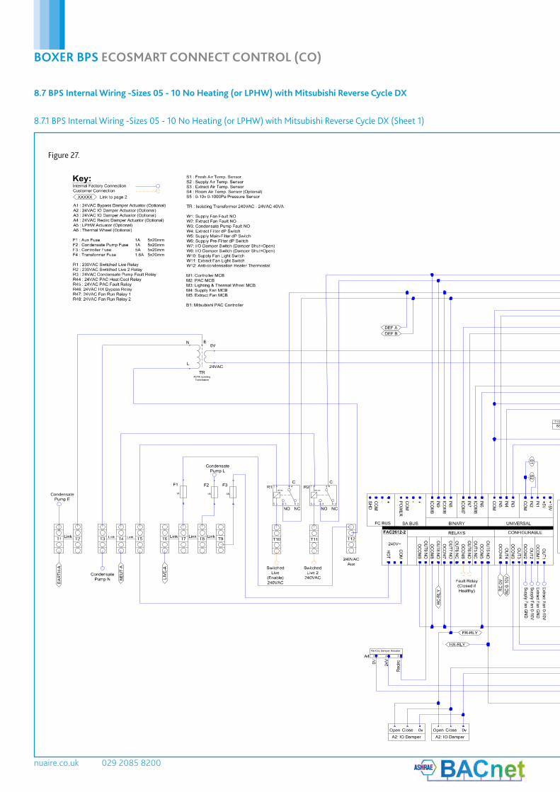
8.7 BPS Internal Wiring -Sizes 05 - 10 No Heating (or LPHW) with Mitsubishi Reverse Cycle DX
8.7.1 BPS Internal Wiring -Sizes 05 - 10 No Heating (or LPHW) with Mitsubishi Reverse Cycle DX (Sheet 1)
Figure 27.
10. 05. 18. Leaflet Number 671828
BOXER BPS ECOSMART CONNECT CONTROL (CO)
33F:\Engineering\Projects\Project Data\Platinum\I&Ms\EcoSmart Connect\Drawings\Connect Control Schematics\Connect Control Diagrams.dwg, 07/11/2017 09:42:55, AutoCAD PDF (Smallest File).pc3

nuaire.co.uk 029 2085 8200
BOXER BPS ECOSMART CONNECT CONTROL (CO)
F:\Engineering\Projects\Project Data\Platinum\I&Ms\EcoSmart Connect\Drawings\Connect Control Schematics\Connect Control Diagrams.dwg, 07/11/2017 09:42:57, AutoCAD PDF (Smallest File).pc3
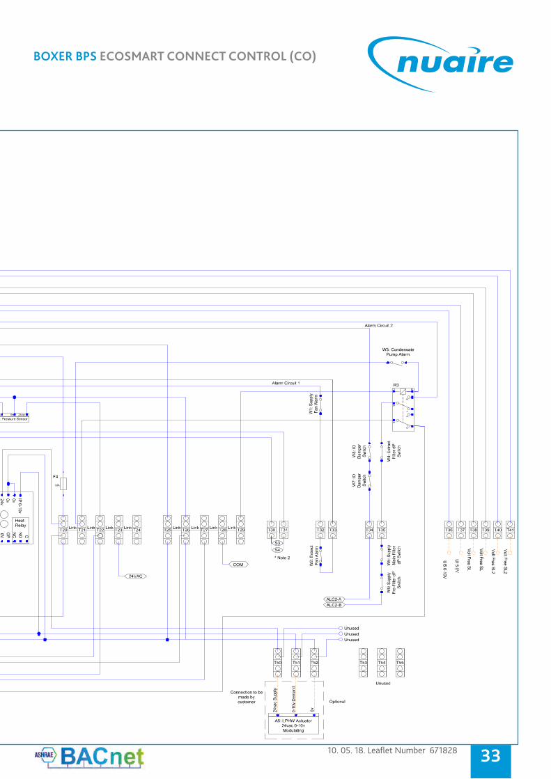
8.7.2 BPS Internal Wiring -Sizes 05 - 10 No Heating (or LPHW) with Mitsubishi Reverse Cycle DX (Sheet 2)
Figure 28.
10. 05. 18. Leaflet Number 671828
BOXER BPS ECOSMART CONNECT CONTROL (CO)
35F:\Engineering\Projects\Project Data\Platinum\I&Ms\EcoSmart Connect\Drawings\Connect Control Schematics\Connect Control Diagrams.dwg, 07/11/2017 09:42:57, AutoCAD PDF (Smallest File).pc3

nuaire.co.uk 029 2085 8200
BOXER BPS ECOSMART CONNECT CONTROL (CO)
F:\Engineering\Projects\Project Data\Platinum\I&Ms\EcoSmart Connect\Drawings\Connect Control Schematics\Connect Control Diagrams.dwg, 07/11/2017 09:42:58, AutoCAD PDF (Smallest File).pc3
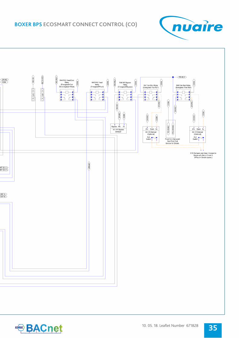
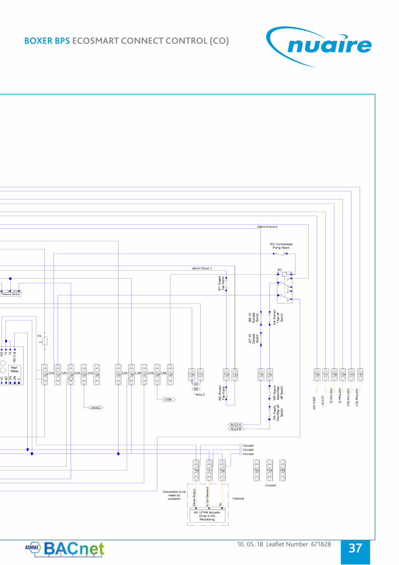
8.8 BPS Internal Wiring -Sizes 15 - 20 No Heating (or LPHW) with Mitsubishi Reverse Cycle DX
8.8.1 BPS Internal Wiring -Sizes 15 - 20 No Heating (or LPHW) with Mitsubishi Reverse Cycle DX (Sheet 1)
Figure 29.
10. 05. 18. Leaflet Number 671828
BOXER BPS ECOSMART CONNECT CONTROL (CO)
37F:\Engineering\Projects\Project Data\Platinum\I&Ms\EcoSmart Connect\Drawings\Connect Control Schematics\Connect Control Diagrams.dwg, 07/11/2017 09:42:58, AutoCAD PDF (Smallest File).pc3

nuaire.co.uk 029 2085 8200
BOXER BPS ECOSMART CONNECT CONTROL (CO)
F:\Engineering\Projects\Project Data\Platinum\I&Ms\EcoSmart Connect\Drawings\Connect Control Schematics\Connect Control Diagrams.dwg, 07/11/2017 09:43:00, AutoCAD PDF (Smallest File).pc3
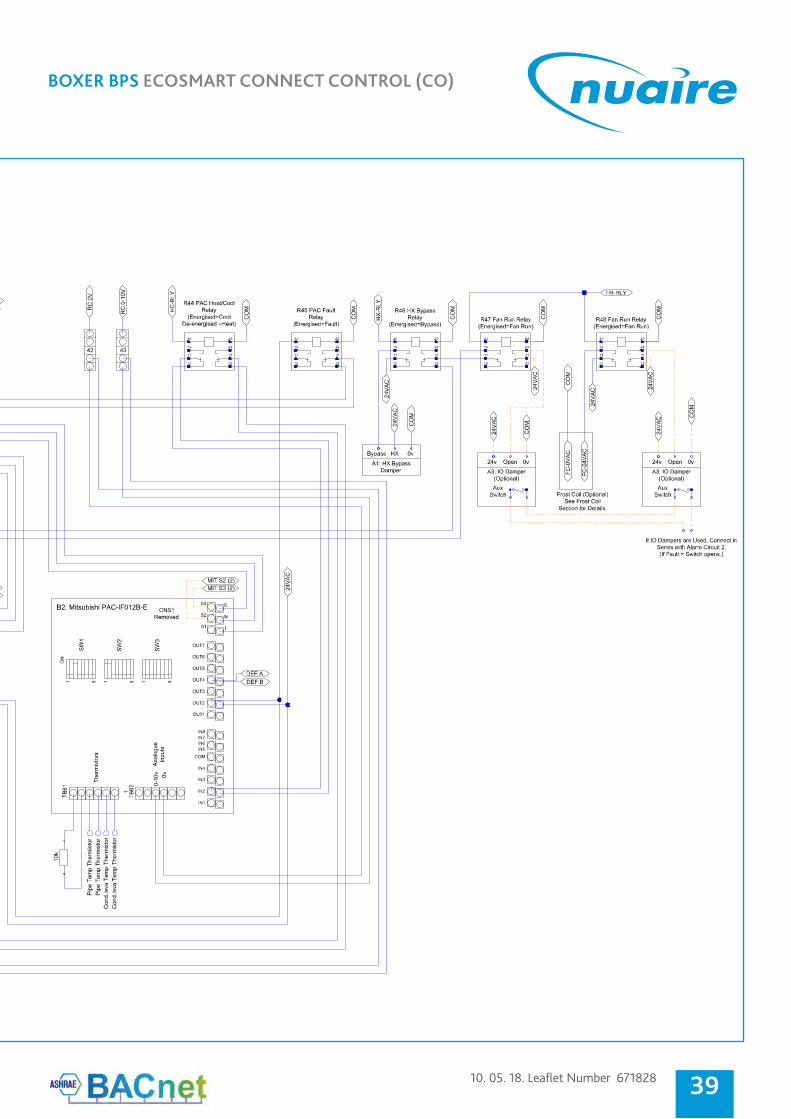
8.8.2 BPS Internal Wiring -Sizes 15 - 20 No Heating (or LPHW) with Mitsubishi Reverse Cycle DX (Sheet 2)
Figure 30.
10. 05. 18. Leaflet Number 671828
BOXER BPS ECOSMART CONNECT CONTROL (CO)
39F:\Engineering\Projects\Project Data\Platinum\I&Ms\EcoSmart Connect\Drawings\Connect Control Schematics\Connect Control Diagrams.dwg, 07/11/2017 09:43:00, AutoCAD PDF (Smallest File).pc3
nuaire.co.uk 029 2085 8200
BOXER BPS ECOSMART CONNECT CONTROL (CO)
F:\Engineering\Projects\Project Data\Platinum\I&Ms\EcoSmart Connect\Drawings\Connect Control Schematics\Connect Control Diagrams.dwg, 07/11/2017 09:43:05, AutoCAD PDF (Smallest File).pc3
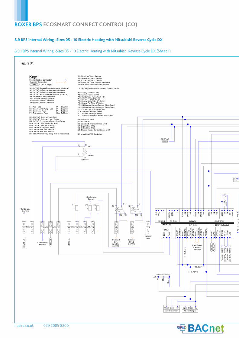
8.9 BPS Internal Wiring -Sizes 05 - 10 Electric Heating with Mitsubishi Reverse Cycle DX
8.9.1 BPS Internal Wiring -Sizes 05 - 10 Electric Heating with Mitsubishi Reverse Cycle DX (Sheet 1)
Figure 31.

10. 05. 18. Leaflet Number 671828
BOXER BPS ECOSMART CONNECT CONTROL (CO)
41F:\Engineering\Projects\Project Data\Platinum\I&Ms\EcoSmart Connect\Drawings\Connect Control Schematics\Connect Control Diagrams.dwg, 07/11/2017 09:43:05, AutoCAD PDF (Smallest File).pc3
nuaire.co.uk 029 2085 8200
BOXER BPS ECOSMART CONNECT CONTROL (CO)
F:\Engineering\Projects\Project Data\Platinum\I&Ms\EcoSmart Connect\Drawings\Connect Control Schematics\Connect Control Diagrams.dwg, 07/11/2017 09:43:07, AutoCAD PDF (Smallest File).pc3
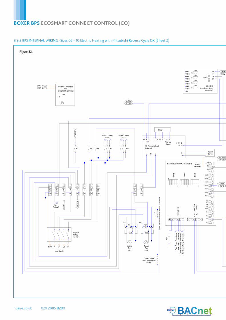
8.9.2 BPS INTERNAL WIRING -Sizes 05 - 10 Electric Heating with Mitsubishi Reverse Cycle DX (Sheet 2)
Figure 32.

10. 05. 18. Leaflet Number 671828
BOXER BPS ECOSMART CONNECT CONTROL (CO)
43F:\Engineering\Projects\Project Data\Platinum\I&Ms\EcoSmart Connect\Drawings\Connect Control Schematics\Connect Control Diagrams.dwg, 07/11/2017 09:43:07, AutoCAD PDF (Smallest File).pc3

nuaire.co.uk 029 2085 8200
BOXER BPS ECOSMART CONNECT CONTROL (CO)
F:\Engineering\Projects\Project Data\Platinum\I&Ms\EcoSmart Connect\Drawings\Connect Control Schematics\Connect Control Diagrams.dwg, 07/11/2017 09:43:09, AutoCAD PDF (Smallest File).pc3
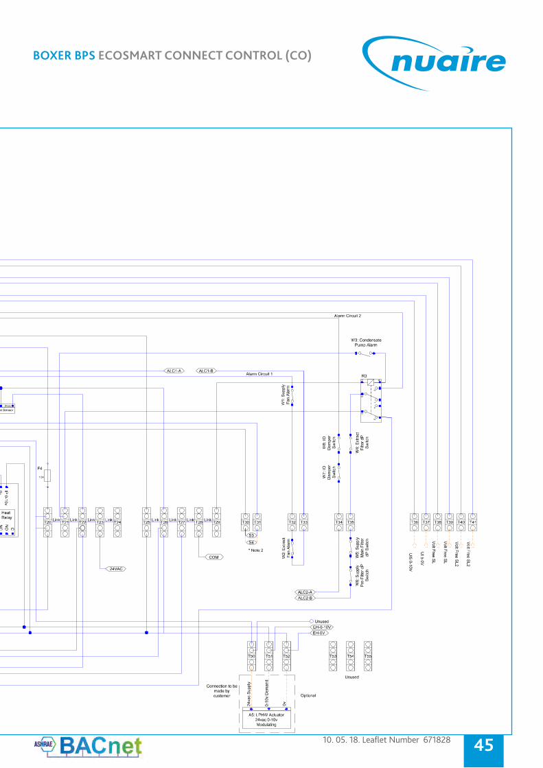
8.10.1 BPS Internal Wiring - Sizes 15 - 20 Electric Heating with Mitsubishi Reverse Cycle DX (Sheet 1)
8.10 BPS Internal Wiring - Sizes 15 - 20 Electric Heating with Mitsubishi Reverse Cycle DX
Figure 33.
10. 05. 18. Leaflet Number 671828
BOXER BPS ECOSMART CONNECT CONTROL (CO)
45F:\Engineering\Projects\Project Data\Platinum\I&Ms\EcoSmart Connect\Drawings\Connect Control Schematics\Connect Control Diagrams.dwg, 07/11/2017 09:43:09, AutoCAD PDF (Smallest File).pc3
nuaire.co.uk 029 2085 8200
BOXER BPS ECOSMART CONNECT CONTROL (CO)
F:\Engineering\Projects\Project Data\Platinum\I&Ms\EcoSmart Connect\Drawings\Connect Control Schematics\Connect Control Diagrams.dwg, 07/11/2017 09:43:10, AutoCAD PDF (Smallest File).pc3
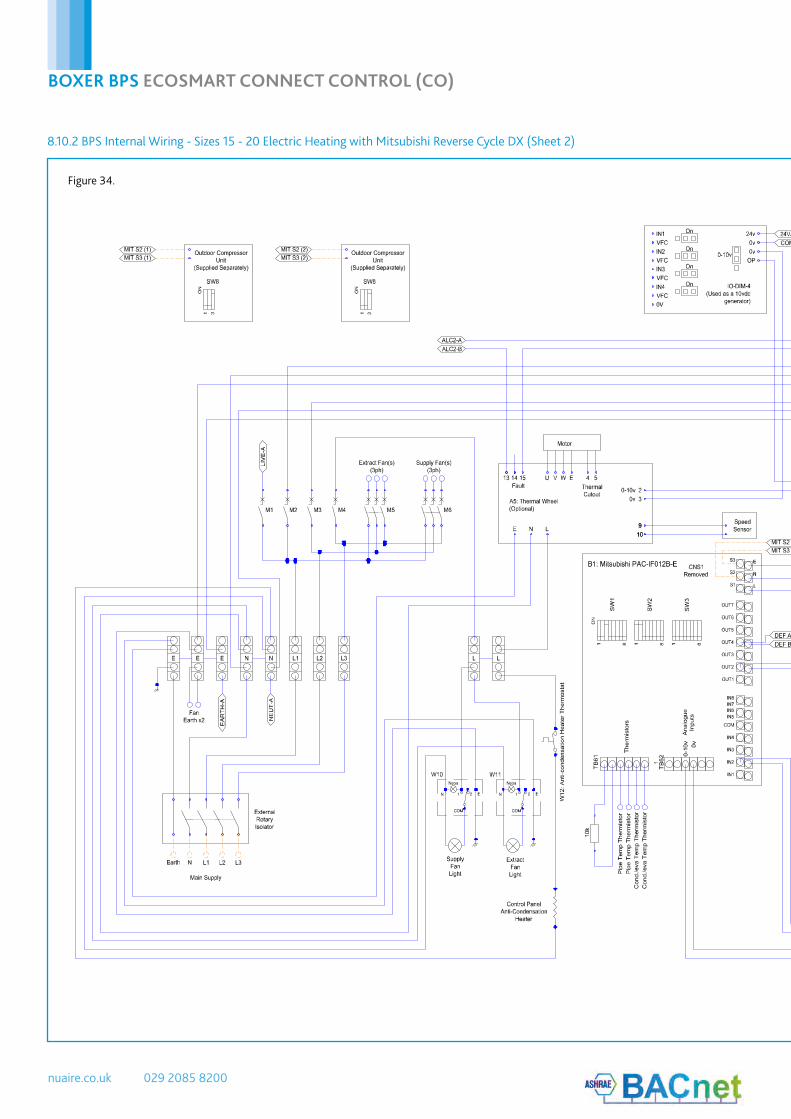
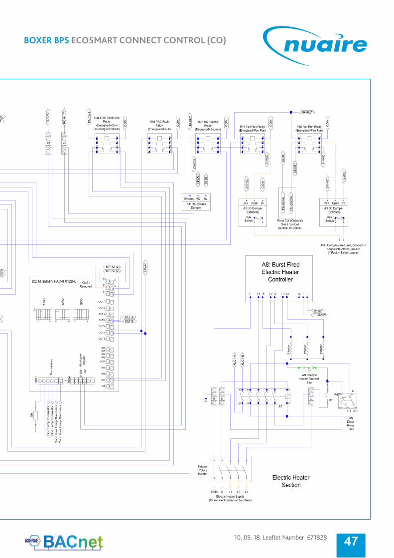
8.10.2 BPS Internal Wiring - Sizes 15 - 20 Electric Heating with Mitsubishi Reverse Cycle DX (Sheet 2)
Figure 34.
10. 05. 18. Leaflet Number 671828
BOXER BPS ECOSMART CONNECT CONTROL (CO)
47F:\Engineering\Projects\Project Data\Platinum\I&Ms\EcoSmart Connect\Drawings\Connect Control Schematics\Connect Control Diagrams.dwg, 07/11/2017 09:43:10, AutoCAD PDF (Smallest File).pc3

nuaire.co.uk 029 2085 8200
BOXER BPS ECOSMART CONNECT CONTROL (CO)
Electric Heater Supply(Overcurrent protection by others)
Earth N
Local Rotary LockableIP66/67 Isolator
L1
Key:Internal Factory ConnectionCustomer Connection
F1 : Fuse 1.6A 5x20mmW1 : Frost Stat
E N
1.6AFuse
F1
GreyBrown Blue
Earth
HealthyCommon Frost
Unused
W1: Frost Stat
BLUE ORANGE GREY
LPHW Actuator Connections(LPHW Actuator by others)
Brown Brown
Black
Blue
Green & Yellow
9.0 FROST COIL
9.2 Frost Coil - Electric Heater
9.1 Frost Coil - LPHW
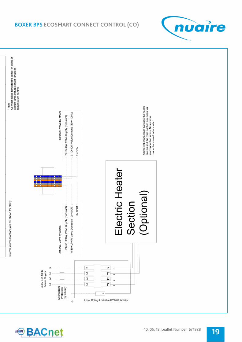
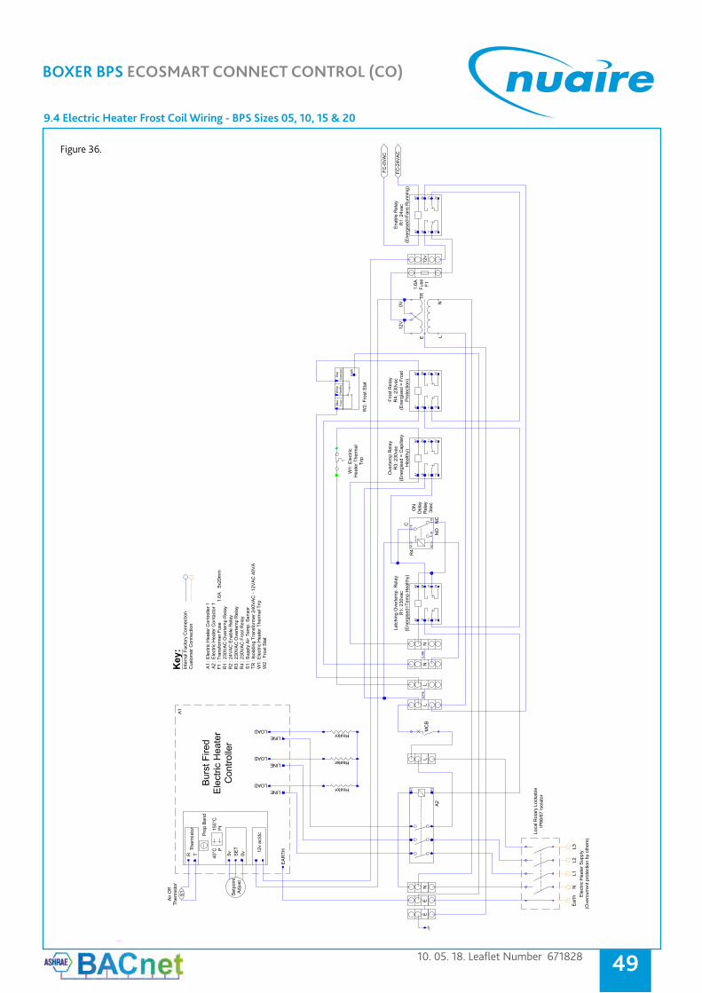
Where they are provided, electric heater frost coils are fitted with its own internal control panel. The control is powered by a 400Vac 50Hz 3 phase & Neutral supply. This must be isolated local to the unit and fitted with appropriate overcurrent and fault protection. It connects to the main unit via “plug and play” interconnecting looms. (See interconnection section for details). No external connections are required. Electric heater elements are protected by a fail-safe over-temperature switch which will disconnect the heater supply if a temperature of 80°C is reached. Once the elements cool, the switch will reset but a power cycle is required to reset the heater supply contactor.
The frost coil is fitted with a burst fired controller with integral setpoint, air off thermistor, air in frost stat, thermal cut-out and contactor. The burst fired controller is only enabled if the frost stat reads a frost condition, the over-temperature cut-out is healthy AND a 24vac fan run signal is received from the main control panel. Once enabled the burst fired controller will increase heating output to achieve the setpoint set by the physical dial on the unit.
Where they are provided, LPHW frost coils are fitted with a frost stat on the air in side and an on/off 230v valve actuator. If the frosts stat switches to a frost condition, the valve actuator will open. The valve will open whether the fans are running or not. This is for pipe freeze protection. The LPHW section requires its own supply in order to power the valve actuator.
9.1.1 Electrical Supply Details - FLC
Unit Size Electric Frost Heater
FLC (Anciliary)
LPHW Frost Coil FLC
(Anciliary)
B*05V/**CO 17.5 A 0.1 A
B*05T/**CO 17.5 A 0.1 A
B*10V/**CO 35 A 0.1 A
B*10T/**CO 35 A 0.1 A
B*15V/**CO 52.5 A 0.1 A
B*15T/**CO 52.5 A 0.1 A
B*20V/**CO 52.5 A 0.1 A
B*20T/**CO 52.5 A 0.1 A
‡ Double electric heater models require separate supplies for two heater
sections, each with an appropriate overcurrent current protection device.
9.3 LPHW Frost Coil Wiring - BPS Sizes 05, 10, 15 & 20
Figure 35.
10. 05. 18. Leaflet Number 671828
BOXER BPS ECOSMART CONNECT CONTROL (CO)
49
9.4 Electric Heater Frost Coil Wiring - BPS Sizes 05, 10, 15 & 20
Figure 36.
nuaire.co.uk 029 2085 8200
BOXER BPS ECOSMART CONNECT CONTROL (CO)
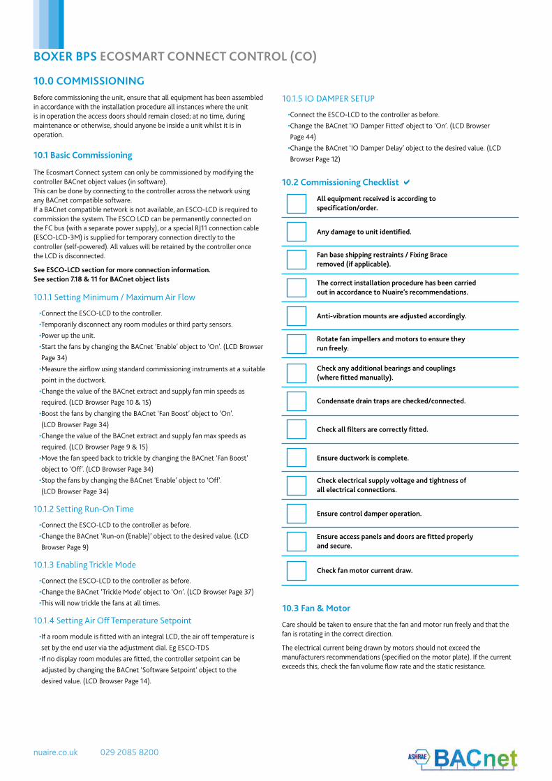
The Ecosmart Connect system can only be commissioned by modifying thecontroller BACnet object values (in software).This can be done by connecting to the controller across the network usingany BACnet compatible software.If a BACnet compatible network is not available, an ESCO-LCD is required tocommission the system. The ESCO LCD can be permanently connected onthe FC bus (with a separate power supply), or a special RJ11 connection cable(ESCO-LCD-3M) is supplied for temporary connection directly to thecontroller (self-powered). All values will be retained by the controller oncethe LCD is disconnected.
See ESCO-LCD section for more connection information. See section 7.18 & 11 for BACnet object lists
10.1 Basic Commissioning
10.1.1 Setting Minimum / Maximum Air Flow
10.1.2 Setting Run-On Time
10.1.4 Setting Air Off Temperature Setpoint
10.1.5 IO DAMPER SETUP
•Connect the ESCO-LCD to the controller.
•Temporarily disconnect any room modules or third party sensors.
•Power up the unit.
•Start the fans by changing the BACnet ‘Enable’ object to ‘On’. (LCD Browser
Page 34)
•Measure the airflow using standard commissioning instruments at a suitable
point in the ductwork.
•Change the value of the BACnet extract and supply fan min speeds as
required. (LCD Browser Page 10 & 15)
•Boost the fans by changing the BACnet ‘Fan Boost’ object to ‘On’.
(LCD Browser Page 34)
•Change the value of the BACnet extract and supply fan max speeds as
required. (LCD Browser Page 9 & 15)
•Move the fan speed back to trickle by changing the BACnet ‘Fan Boost’
object to ‘Off’. (LCD Browser Page 34)
•Stop the fans by changing the BACnet ‘Enable’ object to ‘Off’.
(LCD Browser Page 34)
•Connect the ESCO-LCD to the controller as before.
•Change the BACnet ‘Run-on (Enable)’ object to the desired value. (LCD
Browser Page 9)
•If a room module is fitted with an integral LCD, the air off temperature is
set by the end user via the adjustment dial. Eg ESCO-TDS
•If no display room modules are fitted, the controller setpoint can be
adjusted by changing the BACnet ‘Software Setpoint’ object to the
desired value. (LCD Browser Page 14).
•Connect the ESCO-LCD to the controller as before.
•Change the BACnet ‘IO Damper Fitted’ object to ‘On’. (LCD Browser
Page 44)
•Change the BACnet ‘IO Damper Delay’ object to the desired value. (LCD
Browser Page 12)
10.1.3 Enabling Trickle Mode
•Connect the ESCO-LCD to the controller as before.
•Change the BACnet ‘Trickle Mode’ object to ‘On’. (LCD Browser Page 37)
•This will now trickle the fans at all times.
10.0 COMMISSIONING
10.3 Fan & Motor
Before commissioning the unit, ensure that all equipment has been assembled in accordance with the installation procedure all instances where the unit is in operation the access doors should remain closed; at no time, during maintenance or otherwise, should anyone be inside a unit whilst it is in operation.
Care should be taken to ensure that the fan and motor run freely and that the fan is rotating in the correct direction.
The electrical current being drawn by motors should not exceed the manufacturers recommendations (specified on the motor plate). If the current exceeds this, check the fan volume flow rate and the static resistance.
10.2 Commissioning Checklist a
All equipment received is according tospecification/order.
Condensate drain traps are checked/connected.
Any damage to unit identified.
Check all filters are correctly fitted.
Fan base shipping restraints / Fixing Braceremoved (if applicable).
Ensure ductwork is complete.
The correct installation procedure has been carriedout in accordance to Nuaire’s recommendations.
Check electrical supply voltage and tightness ofall electrical connections.
Anti-vibration mounts are adjusted accordingly.
Ensure control damper operation.
Rotate fan impellers and motors to ensure theyrun freely.
Ensure access panels and doors are fitted properlyand secure.
Check any additional bearings and couplings(where fitted manually).
Check fan motor current draw.

10. 05. 18. Leaflet Number 671828
BOXER BPS ECOSMART CONNECT CONTROL (CO)
51
11.0 MAINTENANCE
11.2 Bearings
11.1 Fans
11.1.1 General Fan Maintenance
11.3 Filters
It is the owner’s responsibility to ensure that the air handling equipment is maintained accordingly. In doing so, regular and scheduled checks will decrease the possibility of unforeseen and possibly costly repairs. Maintenance tasks should be taken care of by a competent person, if system failure occurs due to improper maintenance, Nuaire will not be held liable for the costs of restoring a unit to its previous working condition.
It is recommended that PPE is always used during the maintenance of AirHandling Equipment – gloves, eye shields and respiratory mask.
The bearings that are fitted will be (unless otherwise specified) “sealed for life”, therefore consequence maintenance is not required.
Fan bearings are lifelong; up to 40,000 hours of operation. In cases of heavy duty operation, maintenance intervals are to be established by the operator.
Please refer to general arrangement drawings for details of the type of fan and drive that is fitted. Maintenance guidelines for all fans are beyond this manual, please contact Nuaire for specific documents.
Before any work is carried out, please ensure that:
•The power supply to the motor is switched off.
•The fan impeller is at rest.
•Measures are taken to ensure that the accidental, uncontrolled run-ning of the fan is prevented during maintenance work.
In general, fans should be inspected twice a year, and care should be taken to ensure that any unusual vibration or sound is investigated as an urgent matter.
Access to the fan section is via hinged or lift-off panels. Cable entry must be made through the apertures provided. Screwed glands with cable restraint devices should be used.
•Access to the fan is normally gained by opening the hinged access doors.
•Care should be taken to remove any build up of dust (a light vacuum or light brushing will normally take care of this) Do not use a steam or any other high pressure cleaners.
•Inspect the connection between the fan and unit for any damage or wear and tear.
When removing the filter access panels, pay attention to the airflow direction marked on the panel, this must be replaced to the exact position prior to being removed. Disposable filters should be checked, and changed when they become fully laden with dust. Washable filters should be removed and washed in a mild detergent, flushed with clean water and allowed to dry before refitting.
IMPORTANT
Isolation - Before commencing work make sure that the unit is electrically isolated from the mains unit and sufficient time has
passed to allow the fans to run down (5 minutes minimum).
11.4 Heating & Cooling Coils
11.5 Plate Heat Exchanger
Coils should be connected to ensure that full counter flow exists i.e. - the entering airflow meets the return connection.
All coils should be connected with the flow at the bottom and the return at the top unless otherwise advised. Drain and bleed valves are located on the coil, others may be required in the system pipe-work depending on the installation.
Frost protection must be incorporated on shut down and fresh air conditions to avoid coil freezing. Ideally, where the system is at risk of frost damage, the addition of a proprietary antifreeze solution to the water is recommended.
Pipe-work connections should be made to the unit using appropriate techniques, and must be independently supported. The connections should be pressure tested.
All coils sit in a common drip tray connected to the pre-fittedcondensate pump.
The coil panel has been pre-drilled and fitted with appropriategrommets for pipe connections. Do not drill or cut the unit casing forthis purpose.
Coils should have their finned surface examined for accumulation of dirt, lintand biological contaminants or similar. If necessary, wash down affected areas with a mild detergent solution and a soft brush. Care should be taken not to damage the finned surface, and any cleaning fluids should be rinsed away with water.
A compressed air line may be used to blow out any solids between fins. Donot probe the coil fin block with metal objects as damage may cause leaks.Drain lines should be checked to ensure that they are unobstructed and freedraining. Drain pans should be flushed out periodically to remove contamination.
Note: The unit application may require particular attention to this item –Check with Building Management personnel for details.
The recuperator block is normally protected from dust and contamination by upstream pre-filters. It is possible to clean the unit with compressed air in the case of dust deposits or by spraying with a mild detergent solution for grease deposits.
Solvents, strong alkaline, acidic or any products that may be aggressive to aluminium or plastics should not be used. Do not use cleaning water over 50 deg C.
Drain lines should be checked to ensure that they are unobstructed and free draining. Traps should be checked that they are fully primed and functioning.
Drain pans should be flushed out periodically to remove contamination, and chemical treatments may be used to provide protection between service visits.
Note: The unit application may require particular attention to this item –Check with Building Management personnel for details.
IMPORTANT
Isolation - Before commencing work make sure that the unit is electrically isolated from the mains unit and sufficient time has
passed to allow the fans to run down (5 minutes minimum).
IMPORTANT
If the unit contains a thermal wheel heat exchanger, please ensure that the rotation sensor is aligned with the sensing studs, as
this can become misaligned duringtransport/installation thus causing a fault signal.
nuaire.co.uk 029 2085 8200
BOXER BPS ECOSMART CONNECT CONTROL (CO)
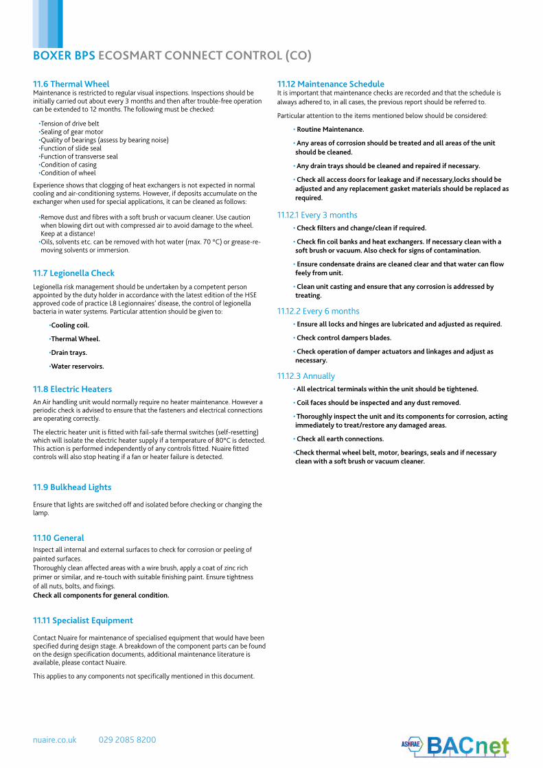
11.7 Legionella CheckLegionella risk management should be undertaken by a competent person appointed by the duty holder in accordance with the latest edition of the HSE approved code of practice L8 Legionnaires’ disease, the control of legionella bacteria in water systems. Particular attention should be given to:
•Cooling coil.
•Thermal Wheel.
•Drain trays.
•Water reservoirs.
11.8 Electric Heaters
11.9 Bulkhead Lights
11.11 Specialist Equipment
An Air handling unit would normally require no heater maintenance. However a periodic check is advised to ensure that the fasteners and electrical connections are operating correctly.
The electric heater unit is fitted with fail-safe thermal switches (self-resetting) which will isolate the electric heater supply if a temperature of 80°C is detected. This action is performed independently of any controls fitted. Nuaire fitted controls will also stop heating if a fan or heater failure is detected.
Ensure that lights are switched off and isolated before checking or changing the lamp.
Contact Nuaire for maintenance of specialised equipment that would have been specified during design stage. A breakdown of the component parts can be found on the design specification documents, additional maintenance literature is available, please contact Nuaire.
This applies to any components not specifically mentioned in this document.
11.6 Thermal WheelMaintenance is restricted to regular visual inspections. Inspections should be initially carried out about every 3 months and then after trouble-free operation can be extended to 12 months. The following must be checked:
Experience shows that clogging of heat exchangers is not expected in normal cooling and air-conditioning systems. However, if deposits accumulate on the exchanger when used for special applications, it can be cleaned as follows:
•Tension of drive belt•Sealing of gear motor•Quality of bearings (assess by bearing noise)•Function of slide seal•Function of transverse seal•Condition of casing•Condition of wheel
•Remove dust and fibres with a soft brush or vacuum cleaner. Use caution when blowing dirt out with compressed air to avoid damage to the wheel. Keep at a distance!
•Oils, solvents etc. can be removed with hot water (max. 70 °C) or grease-re-moving solvents or immersion.
Inspect all internal and external surfaces to check for corrosion or peeling ofpainted surfaces.Thoroughly clean affected areas with a wire brush, apply a coat of zinc richprimer or similar, and re-touch with suitable finishing paint. Ensure tightnessof all nuts, bolts, and fixings. Check all components for general condition.
11.10 General
11.12 Maintenance Schedule
11.12.1 Every 3 months
11.12.2 Every 6 months
11.12.3 Annually
It is important that maintenance checks are recorded and that the schedule is always adhered to, in all cases, the previous report should be referred to.
Particular attention to the items mentioned below should be considered:
• Routine Maintenance.
• Any areas of corrosion should be treated and all areas of the unit should be cleaned.
• Any drain trays should be cleaned and repaired if necessary.
• Check all access doors for leakage and if necessary,locks should be adjusted and any replacement gasket materials should be replaced as required.
• Check filters and change/clean if required.
• Check fin coil banks and heat exchangers. If necessary clean with a soft brush or vacuum. Also check for signs of contamination.
• Ensure condensate drains are cleaned clear and that water can flow feely from unit.
• Clean unit casting and ensure that any corrosion is addressed by treating.
• Ensure all locks and hinges are lubricated and adjusted as required.
• Check control dampers blades.
• Check operation of damper actuators and linkages and adjust as necessary.
• All electrical terminals within the unit should be tightened.
• Coil faces should be inspected and any dust removed.
• Thoroughly inspect the unit and its components for corrosion, acting immediately to treat/restore any damaged areas.
• Check all earth connections.
•Check thermal wheel belt, motor, bearings, seals and if necessary clean with a soft brush or vacuum cleaner.

10. 05. 18. Leaflet Number 671828
BOXER BPS ECOSMART CONNECT CONTROL (CO)
53
5 year warranty on ECOSMART models for peace of mind. The warranty starts from the day of delivery and includes parts and labour for the first year.The remaining period covers replacement parts only.
This warranty is void if the equipment is modified without authorisation, is incorrectly applied, misused, disassembled, or not installed, commissioned and maintained in accordance with the details contained in this manual and general good practice.
If control software is modified or removed Nuaire will accept warranty on the hardware (unit) provided the replacement does not control the unit beyond its specified limits (refer to Nuaire testing standards and Application Guidance Notes document NA-QS-W029-3 which can be found on our website www.nuaire.co.uk).
The product warranty applies to the UK mainland and in accordance with Clause 14 of our Conditions of Sale. Customers purchasing from outside of the UK should contact Nuaire International Sales office for further details.
12.0 WARRANTY
13.0 AFTER SALESFor technical assistance or further product information, including spare parts and replacement components, please contact the After Sales Department.
02920 858 400 [email protected]

nuaire.co.uk 029 2085 8200
BOXER BPS ECOSMART CONNECT CONTROL (CO)
19.0 CERTIFICATION
DECLARATION OF INCORPORATION AND INFORMATION FOR SAFE INSTALLATION, OPERATION AND MAINTENANCE
INFORMATION FOR SAFE INSTALLATION, OPERATION AND MAINTENANCEOF NUAIRE VENTILATION EQUIPMENT
We declare that the machinery named below is intended to be assembled withother components to constitute a system of machinery. All partsexcept for moving parts requiring the correct installation of safety guards complywith the essential requirements of the Machinery Directive. Themachinery shall not be put into service until the system has beendeclared to be in conformity with the provisions of the EC MachineryDirective.
Designation of machinery:
Machinery Types:
Relevant EC Council Directives: 2006/42/EC (Machinery Directive)
Applied Harmonised Standards: BS EN ISO 12100, BS EN ISO 13857 EN60204-1, BS EN ISO 9001
Applied National Standards: BS848 Parts 1, 2.2 and 5
Note: All standards used were current and valid at the date of signature.
Signature of manufacture representatives:Name: Position: Date:
1)C. Biggs Technical Director
2)A. Jones Manufacturing Director
Technical or commercial considerations may, from time to time, make it necessary to alter the design, performance anddimensions of equipment and the right is reserved to make such changes without prior notice.
To comply with EC Council Directives 2006/42/EC Machinery Directiveand 2004/108/EC (EMC).To be read in conjunction with the relevant Product Documentation (see 2.1)
1.0 GENERAL
1.1 The equipment referred to in this Declaration of Incorporation is supplied by Nuaire to be assembled into a ventilation system which may or may not include additional components. The entire system must be considered for safety purposes and it is the responsibility of the installer to ensure that all of the equipment is installed in compliance with the manufacturers recommendations and with due regard to current legislation and codes of practice.
2.0 INFORMATION SUPPLIED WITH THE EQUIPMENT
2.1 Each item of equipment is supplied with a set of documentation which provides the information required for the safe installation and maintenance of the equipment. This may be in the form of a Data sheet and/or Installation and Maintenance instruction.2.2 Each unit has a rating plate attached to its outer casing. The rating plate provides essential data relating to the equipment such as serial number, unit code and electrical data. Any further data that may be required will be found in the documentation. If any item is unclear or more information is required, contact Nuaire.2.3 Where warning labels or notices are attached to the unit the instructions given must be adhered to.
3.0 TRANSPORTATION, HANDLING AND STORAGE
3.1 Care must be taken at all times to prevent damage to the equipment. Note that shock to the unit may result in the balance of the impeller being affected.3.2 When handling the equipment, care should be taken with corners and edges and that the weight distribution within the unit is considered. Lifting gear such as slings or ropes must be arranged so as not to bear on the casing.3.3 Equipment stored on site prior to installation should be protected from the weather and steps taken to prevent ingress of contaminants.
4.0 OPERATIONAL LIMITS
4.1 It is important that the specified operational limits for the equipment are adhered to e.g. operational air temperature, air borne contaminants and unit orientation.4.2 Where installation accessories are supplied with the specified equipment eg. wall mounting brackets. They are to be used to support the equipment only. Other system components must have separate provision for support.4.3 Flanges and connection spigots are provided for the purpose of joining to duct work systems. They must not be used to support the ductwork.4.4 Local Environment - Humidity. Ambient humidity (the humidity at the unit’s installed location) shall be within the range: 10 to 95% (for controls, non-condensing). Air humidity (the humidity of the air passing through the unit) shall be within the range: 10 to 95% (for controls, non-condensing).
5.0 INSTALLATION REQUIREMENTS
In addition to the particular requirements given for the individual product, the following general requirements should be noted.5.1 Where access to any part of equipment which moves, or can become electrically live are not prevented by the equipment panels or by fixed installation detail (e.g. ducting), then guarding to the appropriate standard must be fitted.5.2 The electrical installation of the equipment must comply with the requirements of the relevant local electrical safety regulations.5.3 For EMC all control and sensor cables should not be placed within 50mm or on the same metal cable tray as 230V switched live, lighting or power cables and any cables not intended for use with this product.
6.0 COMMISSIONING REQUIREMENTS
6.1 General pre-commissioning checks relevant to safe operation consist of the following: Ensure that no foreign bodies are present within the fan or casing. Check electrical safety. e.g. Insulation and earthing. Check guarding of system. Check operation of Isolators/Controls. Check fastenings for security.6.2 Other commissioning requirements are given in the relevant product documentation.
7.0 OPERATIONAL REQUIREMENTS
7.1 Equipment access panels must be in place at all times during operation of the unit, and must be secured with the original fastenings.7.2 If failure of the equipment occurs or is suspected then it should be taken out of service until a competent person can effect repair or examination. (Note that certain ranges of equipment are designed to detect and compensate for fan failure).
8.0 MAINTENANCE REQUIREMENTS
8.1 Specific maintenance requirements are given in the relevant product documentation.8.2 It is important that the correct tools are used for the various tasks required.8.3 If the access panels are to be removed for any reason the electrical supply to the unit must be isolated.8.4 A minimum period of two minutes should be allowed after electrical disconnection before access panels are removed. This will allow the impeller to come to rest. NB: Care should still be taken however since airflow generated at some other point in the system can cause the impeller to “windmill” even when power is not present.8.5 Care should be taken when removing and storing access panels in windy conditions.
XBOXER BPS models
Supply & Extract fans with Heat Recovery
18. 06. 16
18. 06. 16

10. 05. 18. Leaflet Number 671828
BOXER BPS ECOSMART CONNECT CONTROL (CO)
55
NOTES

COMMERCIAL www.nuaire.co.uk/commercial
FOR MORE INFORMATION www.nuaire.co.uk
Nuaire: A Trading Version of Polypipe LimitedWestern Industrial Estate | Caerphilly | CF83 1NA
t +44 (0)29 2085 8200 | f +44 (0)29 2085 8222 | e [email protected]
www.nuaire.co.uk
10. 05. 18. Leaflet Number 671828
As part of our policy of continuous product development Nuaire reserves the right to alter specifications without prior notice. Telephone calls may be recorded for quality and training purposes.