installation manual activa+ op. single - manusa.parkan.ua · manusa i 100 activa+ single slide...
TRANSCRIPT
installation manual
Activa+ op. single
i
manusafragil
fragil
GV
Ref.
Ref.
* BRCVLT
* KEGV15LT
CJGV03
Ref.
CACV04
Ref.
APGV04
Ref.
Packaging
DTMJOVL101EN - v1 - ENGLISH ACTIVA+ SINGLE SLIDE OPERATOR INSTALLATION S1
Installation Step#1Activa+ single slide operator
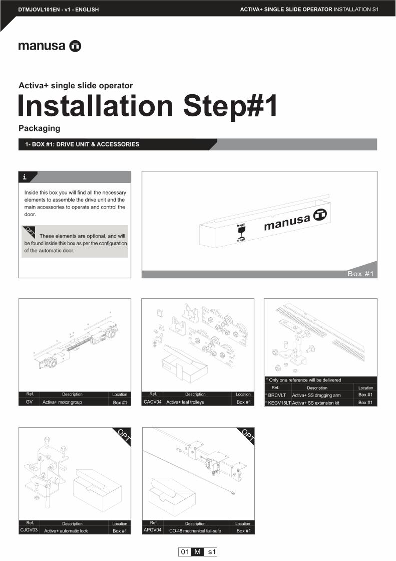
1- BOX #1: DRIVE UNIT & ACCESSORIES
OPT
OPT
Activa+ leaf trolleys Box #1
Description Location
Activa+ automatic lock
Description Location
Box #1
Description Location
CO-48 mechanical fail-safe Box #1
Description Location
Box #1
OPT
Inside this box you will find all the necessary
elements to assemble the drive unit and the
main accessories to operate and control the
door.
These elements are optional, and will
be found inside this box as per the configuration
of the automatic door.
Activa+ motor group
Description Location
Box #1
Box #1
* Only one reference will be delivered
Box #1
01 M s1
Activa+ SS dragging arm
Activa+ SS extension kit
EDFM01
Ref.
EDFE01
Ref.
EDDP01
manusa
Ref.
EDRM04
Ref.
EMPA01
Ref.
EMSR03
Ref.
manusa
EMSM03
Ref.
EMMD04
Ref.
EMLL01
Ref.
EDAA01
Ref.
....------------
Ref.
EDRM05
Ref.
ACTIVA+ SINGLE SLIDE OPERATOR INSTALLATION S1
OPT
OPT
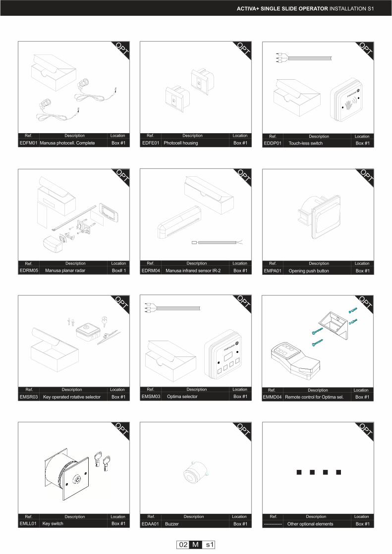
Key switch Box #1
Description Location
Opening push button Box #1
Description Location
OPT
Touch-less switch Box #1
Description Location
Optima selector Box #1
Description Location
OPT
Manusa infrared sensor IR-2 Box #1
Description Location
OPT
Remote control for Optima sel. Box #1
Description Location
OPT
Buzzer Box #1
Description Location
OPT
Manusa photocell. Complete Box #1
Description Location
OPT
Key operated rotative selector Box #1
Description Location
OPT
Other optional elements Box #1
Description Location
OPT
Photocell housing Box #1
Description Location
OPT
02 M s1
Manusa planar radar
Description Location
Box# 1
OPT
i
PACVPC29
Ref.
CSPR
Ref.
KSCVPC01
Ref. Ref.
KSCVPC03
Ref.
JF06
PACVPLP2
Ref.
KSCVPC02
Ref.
ACTIVA+ SINGLE SLIDE OPERATOR INSTALLATION S1
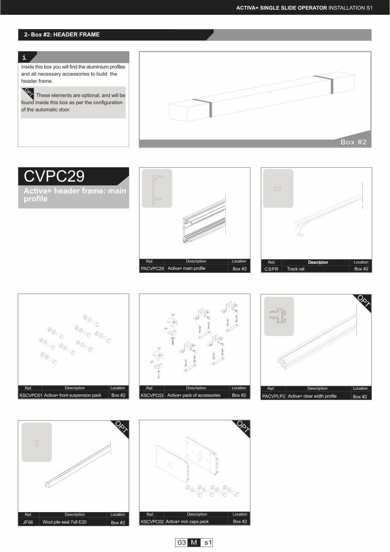
2- Box #2: HEADER FRAME
Activa+ header frame: mainprofile
CVPC29
Activa+ front suspension pack Box #2
03 M s1
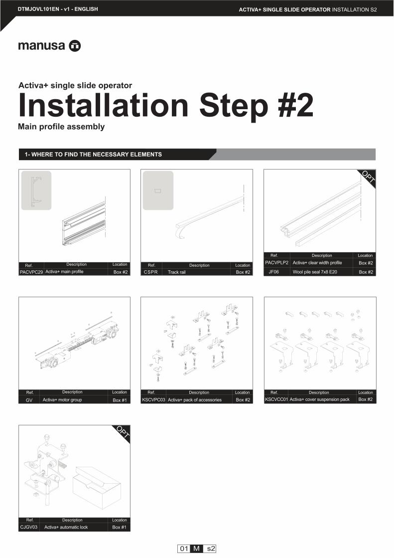
Track rail
Description Location
Description Location
Activa+ pack of accessories
Description Location
Box #2
Description Location
Wool pile seal 7x8 E20 Box #2
Activa+ clear width profile
Description Location
Box #2
Activa+ main profile Box #2
Description Location
OPT
Inside this box you will find the aluminium profiles
and all necessary accessories to build the
header frame.
These elements are optional, and will be
found inside this box as per the configuration
of the automatic door.
Box #2
Description
Box #2
OPT
OPT
Activa+ iron caps pack Box #2
Description Location
OPT
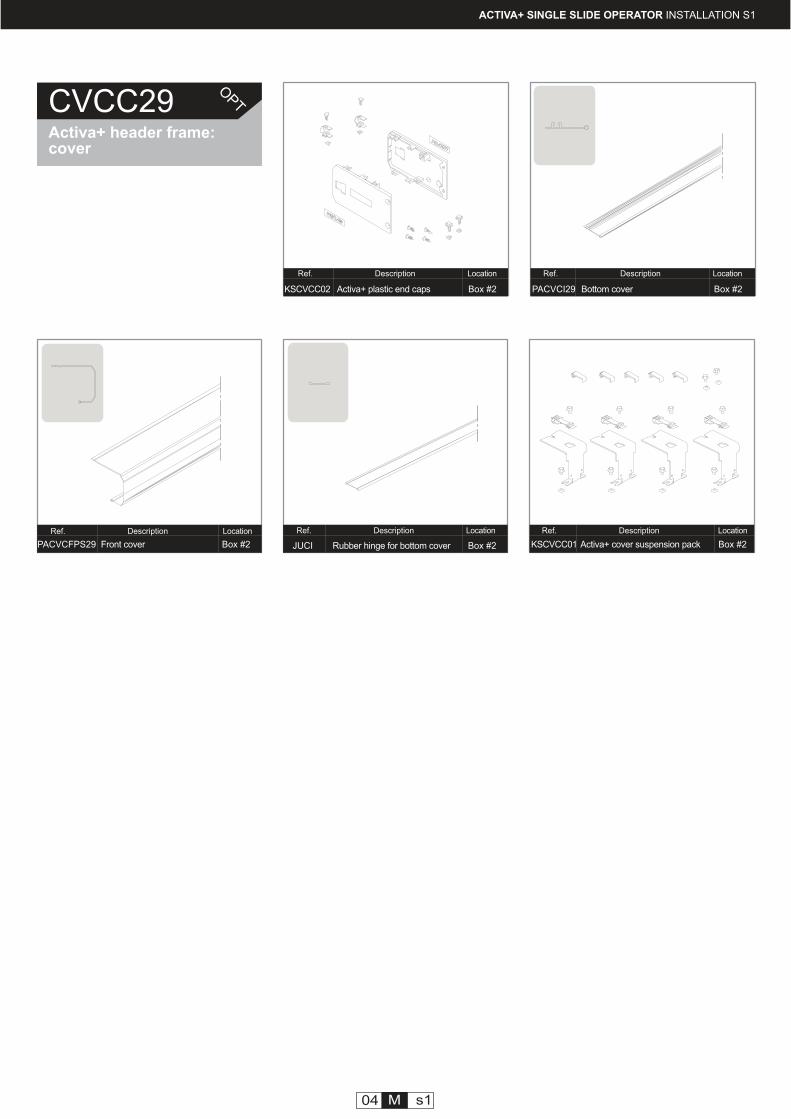
KSCVCC02
Ref.
PACVCI29
Ref.
KSCVCC01
Ref.
JUCI
Ref.
PACVCFPS29
Ref.
ACTIVA+ SINGLE SLIDE OPERATOR INSTALLATION S1
04 M s1
Activa+ plastic end caps Box #2
Description Location
Rubber hinge for bottom cover Box #2
Description Location
Bottom cover Box #2
Description Location
Front cover Box #2
Description Location
Activa+ cover suspension pack Box #2
Description Location
CVCC29Activa+ header frame:cover
OPT
ii
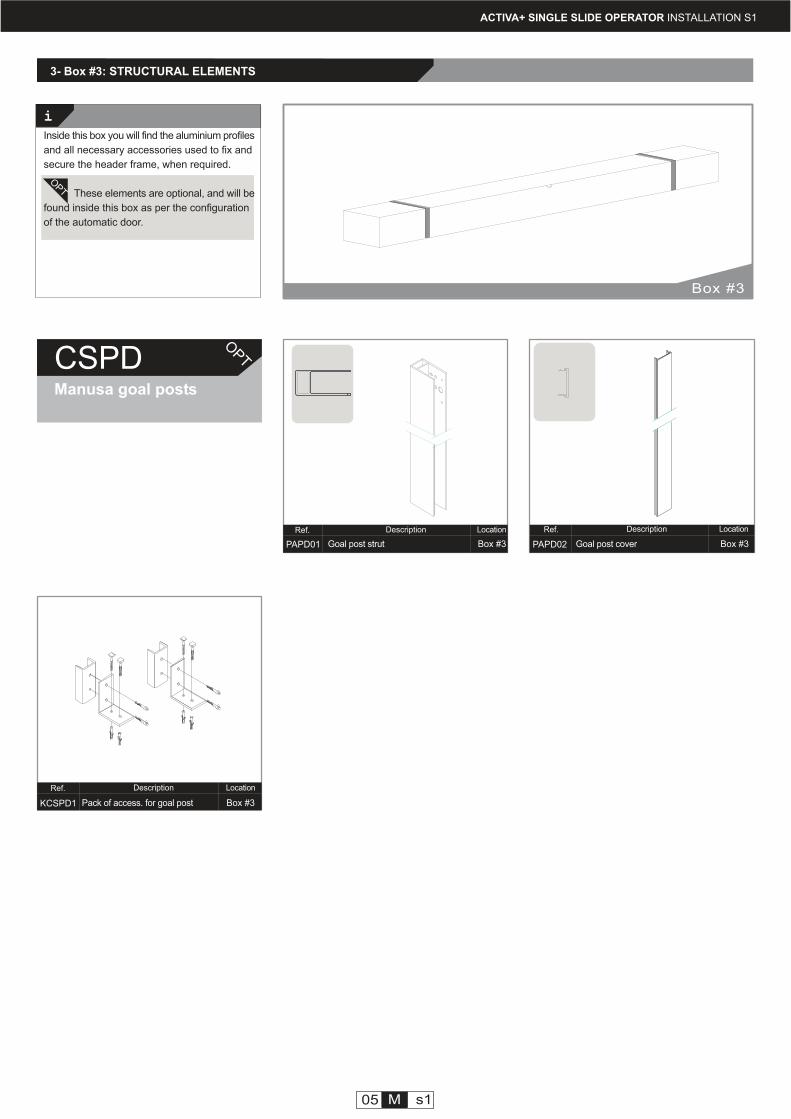
PAPD01
Ref.
PAPD02
Ref.
KCSPD1
Ref.
CSPDManusa goal posts
OPT
OPT
Goal post strut Box #3
05 M s1
Goal post cover Box #3
Description LocationDescription Location
Pack of access. for goal post Box #3
Description Location
Box #3
Inside this box you will find the aluminium profiles
and all necessary accessories used to fix and
secure the header frame, when required.
These elements are optional, and will be
found inside this box as per the configuration
of the automatic door.
3- Box #3: STRUCTURAL ELEMENTS
ACTIVA+ SINGLE SLIDE OPERATOR INSTALLATION S1
PACVPC29
Ref.
CSPR
Ref. PACVPLP2
Ref.
JF06
Ref.
KSCVPC03
CJGV03
Ref.
GV
Ref.
KSCVCC01
Ref.
01 M s2
Track rail Box #2
Description Location
Activa+ pack of accessories
Description Location
Box #2
Activa+ clear width profile
Description Location
Activa+ automatic lock
Description Location
Wool pile seal 7x8 E20
Box #1
Box #2
Box #2Activa+ main profile Box #2
Description Location
Activa+ motor group
Description Location
Box #1
Installation Step #2
1- WHERE TO FIND THE NECESSARY ELEMENTS
Main profile assembly
DTMJOVL101EN - v1 - ENGLISH ACTIVA+ SINGLE SLIDE OPERATOR INSTALLATION S2
Activa+ single slide operator
OPT
OPT
Activa+ cover suspension pack Box #2
Description Location
25
25
a
a
a
a
32
R5.
520
i
i
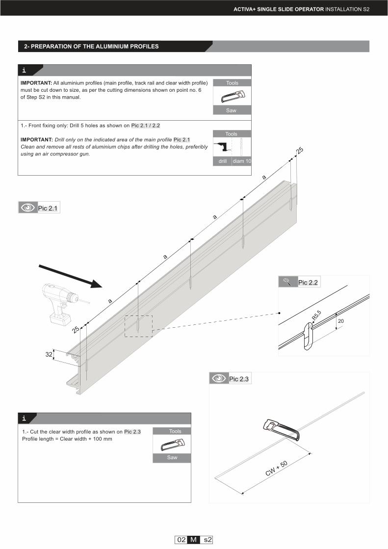
2- PREPARATION OF THE ALUMINIUM PROFILES
Tools
Saw
Tools
drill diam 10
IMPORTANT: All aluminium profiles (main profile, track rail and clear width profile)
must be cut down to size, as per the cutting dimensions shown on point no. 6
of Step S2 in this manual.
1.- Front fixing only: Drill 5 holes as shown on Pic 2.1 / 2.2
IMPORTANT: Drill only on the indicated area of the main profile Pic 2.1
Clean and remove all rests of aluminium chips after drilling the holes, preferibly
using an air compressor gun.
1.- Cut the clear width profile as shown on Pic 2.3
Profile length = Clear width + 100 mm
Pic 2.2
Pic 2.3
Pic 2.1
Tools
Saw
ACTIVA+ SINGLE SLIDE OPERATOR INSTALLATION S2
CW+ 50
02 M s2
i
A
B
15mm
i
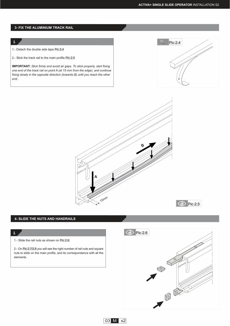
3- FIX THE ALUMINIUM TRACK RAIL
4- SLIDE THE NUTS AND HANDRAILS
03 M s2
1.- Detach the double side tape Pic 2.4
2.- Stick the track rail to the main profile Pic 2.5
IMPORTANT: Stick firmly and avoid air gaps. To stick properly, start fixing
one end of the track rail on point A (at 15 mm from the edge), and continue
fixing slowly in the opposite direction (towards B) until you reach the other
end..
1.- Slide the rail nuts as shown on Pic 2.6.
2.- On Pic 2.7/2.8 you will see the right number of rail nuts and square
nuts to slide on the main profile, and its correspondance with all the
elements.
Pic 2.4
Pic 2.6
Pic 2.5
ACTIVA+ SINGLE SLIDE OPERATOR INSTALLATION S2
i
manusa
1
2
3
4
5
2
3
2
ACTIVA+ SINGLE SLIDE OPERATOR INSTALLATION S2
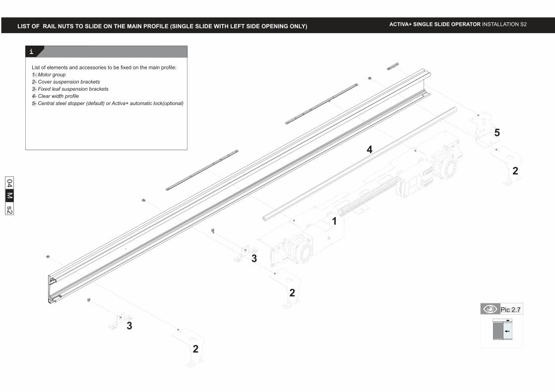
List of elements and accessories to be fixed on the main profile:
1- Motor group
2- Cover suspension brackets
3- Fixed leaf suspension brackets
4- Clear width profile
5- Central steel stopper (default) or Activa+ automatic lock(optional)
04
M s
2
Pic 2.7
LIST OF RAIL NUTS TO SLIDE ON THE MAIN PROFILE (SINGLE SLIDE WITH LEFT SIDE OPENING ONLY)
i
2
manusa
4
5
2
1
3
2
3
ACTIVA+ SINGLE SLIDE OPERATOR INSTALLATION S2
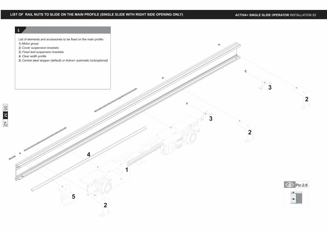
List of elements and accessories to be fixed on the main profile:
1- Motor group
2- Cover suspension brackets
3- Fixed leaf suspension brackets
4- Clear width profile
5- Central steel stopper (default) or Activa+ automatic lock(optional)
05
M s
2
Pic 2.8
LIST OF RAIL NUTS TO SLIDE ON THE MAIN PROFILE (SINGLE SLIDE WITH RIGHT SIDE OPENING ONLY)
i
manusa
a
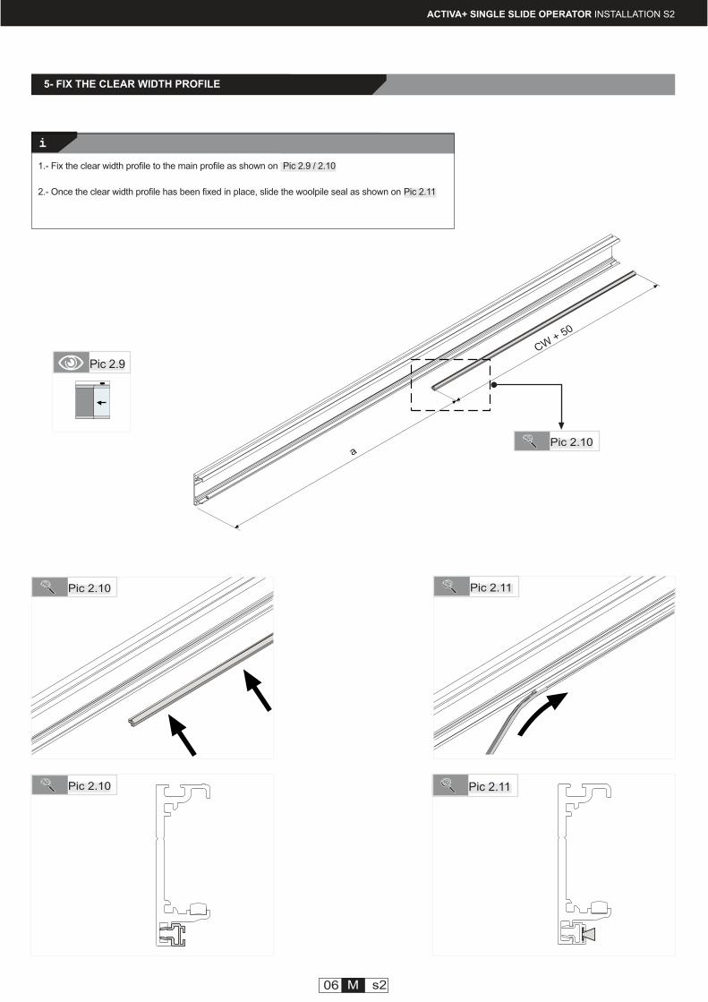
5- FIX THE CLEAR WIDTH PROFILE
Pic 2.11
Pic 2.9
Pic 2.11
1.- Fix the clear width profile to the main profile as shown on Pic 2.9 / 2.10
2.- Once the clear width profile has been fixed in place, slide the woolpile seal as shown on Pic 2.11
ACTIVA+ SINGLE SLIDE OPERATOR INSTALLATION S2
Pic 2.10
Pic 2.10
Pic 2.10
06 M s2
CW+ 50
i
manusa
2900
2900
2900
-------
2900
2900
-------
PACVPC41
CSPR
PACVPLP2
JF06
PACVCFPS
PACVCIPS
JUCI
ACTIVA+ SINGLE SLIDE OPERATOR INSTALLATION S2
07 M s2
( CW X 2 ) + 50
CW
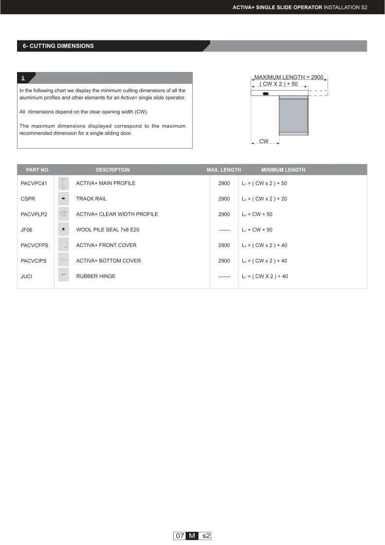
6- CUTTING DIMENSIONS
In the following chart we display the minimum cutting dimensions of all the
aluminium profiles and other elements for an Activa+ single slide operator.
All dimensions depend on the clear opening width (CW).
The maximum dimensions displayed correspond to the maximum
recommended dimension for a single sliding door.
MAXIMUM LENGTH = 2900
L1 = ( CW x 2 ) + 50
L2 = ( CW x 2 ) + 20
L3 = CW + 50
L4 = CW + 50
L5 = ( CW x 2 ) + 40
L6 = ( CW x 2 ) + 40
L7 = ( CW X 2 ) + 40
PART NO. DESCRIPTION MAX. LENGTH MINIMUM LENGTH
ACTIVA+ MAIN PROFILE
TRACK RAIL
ACTIVA+ CLEAR WIDTH PROFILE
WOOL PILE SEAL 7x8 E20
ACTIVA+ FRONT COVER
ACTIVA+ BOTTOM COVER
RUBBER HINGE
CACV04
Ref.
Ref.
* BRCVLT
* KEGV15LT
Ref.
KSCVPC03
GV
Ref.
01 M s3
DTMJOVL101EN - v1 - ENGLISH ACTIVA+ SINGLE SLIDE OPERATOR INSTALLATION S3
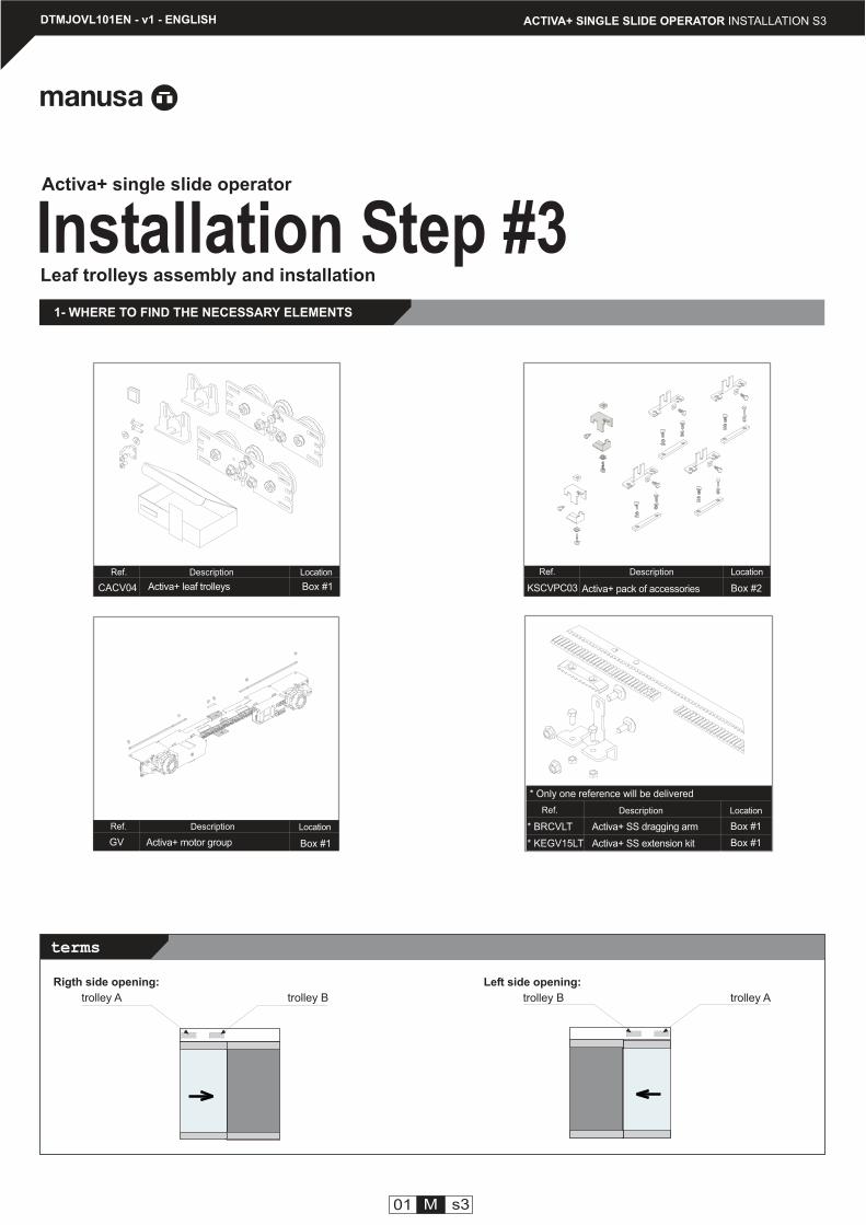
Installation Step #3Activa+ single slide operator
Activa+ pack of accessories
Description Location
Box #2Activa+ leaf trolleys Box #1
Description Location
Activa+ motor group
Description Location
Box #1
1- WHERE TO FIND THE NECESSARY ELEMENTS
Leaf trolleys assembly and installation
* Only one reference will be delivered
Description
Rigth side opening:
trolley A trolley B
Left side opening:
trolley B trolley A
Box #1
Location
Box #1
Activa+ SS dragging arm
Activa+ SS extension kit
terms
i
i
02 M s3
ACTIVA+ SINGLE SLIDE OPERATOR INSTALLATION S3
Pic 3.1
Tools
nº10-11/nº12-13
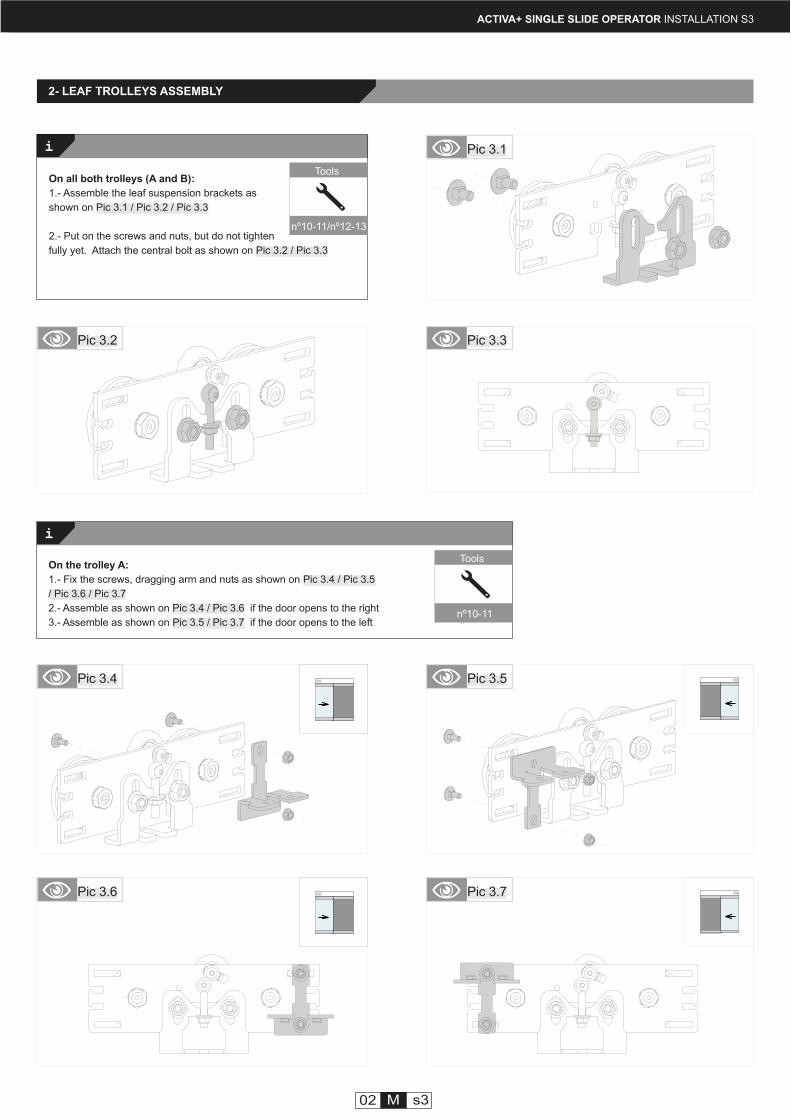
On all both trolleys (A and B):
1.- Assemble the leaf suspension brackets as
shown on Pic 3.1 / Pic 3.2 / Pic 3.3
2.- Put on the screws and nuts, but do not tighten
fully yet. Attach the central bolt as shown on Pic 3.2 / Pic 3.3
2- LEAF TROLLEYS ASSEMBLY
Pic 3.3Pic 3.2
Tools
nº10-11
Pic 3.4 Pic 3.5
Pic 3.6 Pic 3.7
On the trolley A:
1.- Fix the screws, dragging arm and nuts as shown on Pic 3.4 / Pic 3.5
/ Pic 3.6 / Pic 3.7
2.- Assemble as shown on Pic 3.4 / Pic 3.6 if the door opens to the right
3.- Assemble as shown on Pic 3.5 / Pic 3.7 if the door opens to the left
manusa
i
ACTIVA+ SINGLE SLIDE OPERATOR INSTALLATION S3
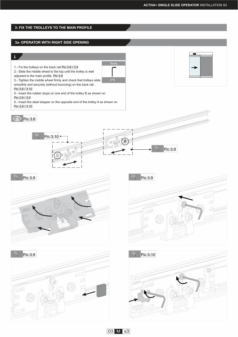
1.- Fix the trolleys on the track rail Pic 3.8 / 3.9
2.- Slide the middle wheel to the top until the trolley is well
adjusted to the main profile. Pic 3.9
3.- Tighten the middle wheel firmly and check that trolleys slide
smoothly and securely (without bouncing) on the track rail .
Pic 3.8 / 3.10
4.- Insert the rubber stops on one end of the trolley B as shown on
Pic 3.8 / 3.9
5.- Insert the steel stopper on the opposite end of the trolley A as shown on
Pic 3.8 / 3.10
3- FIX THE TROLLEYS TO THE MAIN PROFILE
Tools
nº4
Pic 3.8
Pic 3.10
Pic 3.9 Pic 3.9
Pic 3.9
03 M s3
Pic 3.10
Pic 3.9
3a- OPERATOR WITH RIGHT SIDE OPENING
manusa
i
ACTIVA+ SINGLE SLIDE OPERATOR INSTALLATION S3
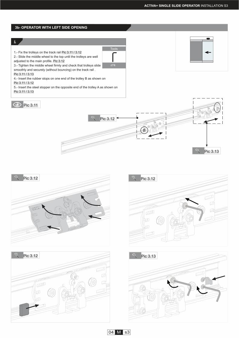
1.- Fix the trolleys on the track rail Pic 3.11 / 3.12
2.- Slide the middle wheel to the top until the trolleys are well
adjusted to the main profile. Pic 3.12
3.- Tighten the middle wheel firmly and check that trolleys slide
smoothly and securely (without bouncing) on the track rail .
Pic 3.11 / 3.13
4.- Insert the rubber stops on one end of the trolley B as shown on
Pic 3.11 / 3.12
5.- Insert the steel stopper on the opposite end of the trolley A as shown on
Pic 3.11 / 3.13
Tools
nº4
Pic 3.11
Pic 3.13
Pic 3.12
Pic 3.12 Pic 3.12
Pic 3.12 Pic 3.13
04 M s3
3b- OPERATOR WITH LEFT SIDE OPENING
manusa
i
100
ACTIVA+ SINGLE SLIDE OPERATOR INSTALLATION S3
Tools
nº10
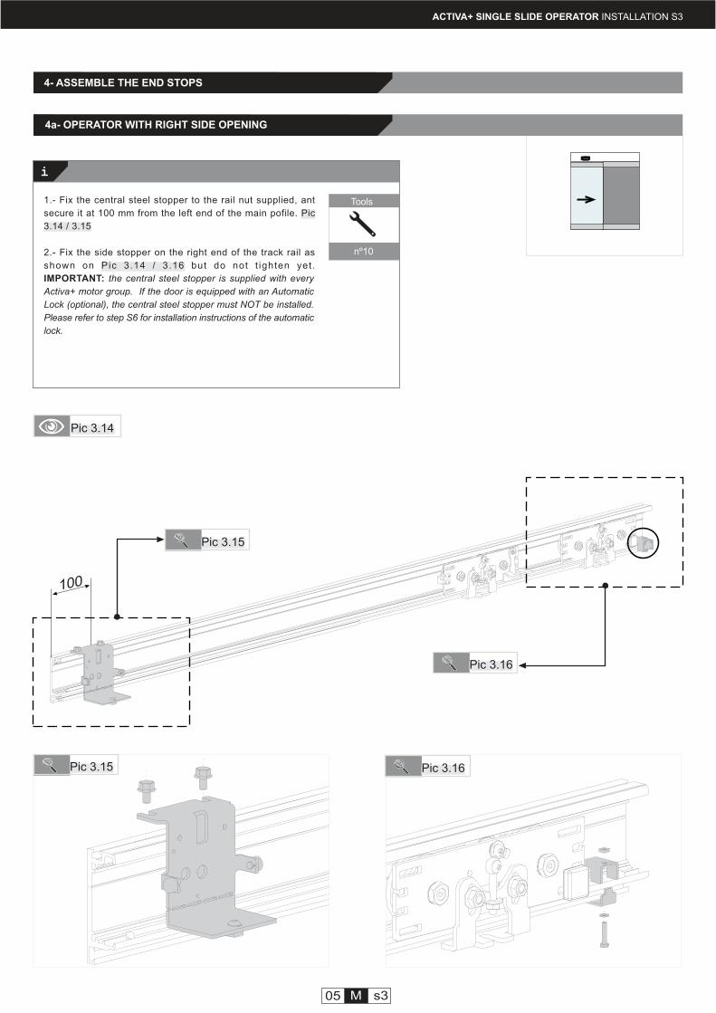
IMPORTANT: the central steel stopper is supplied with every
Activa+ motor group. If the door is equipped with an Automatic
Lock (optional), the central steel stopper must NOT be installed.
Please refer to step S6 for installation instructions of the automatic
lock.
4- ASSEMBLE THE END STOPS
Pic 3.14
Pic 3.15
Pic 3.16
Pic 3.16
Pic 3.15
05 M s3
4a- OPERATOR WITH RIGHT SIDE OPENING
1.- Fix the central steel stopper to the rail nut supplied, ant
secure it at 100 mm from the left end of the main pofile. Pic
3.14 / 3.15
2.- Fix the side stopper on the right end of the track rail as
shown on Pic 3.14 / 3.16 but do not t ighten yet .
100
manusa
i
Tools
nº10
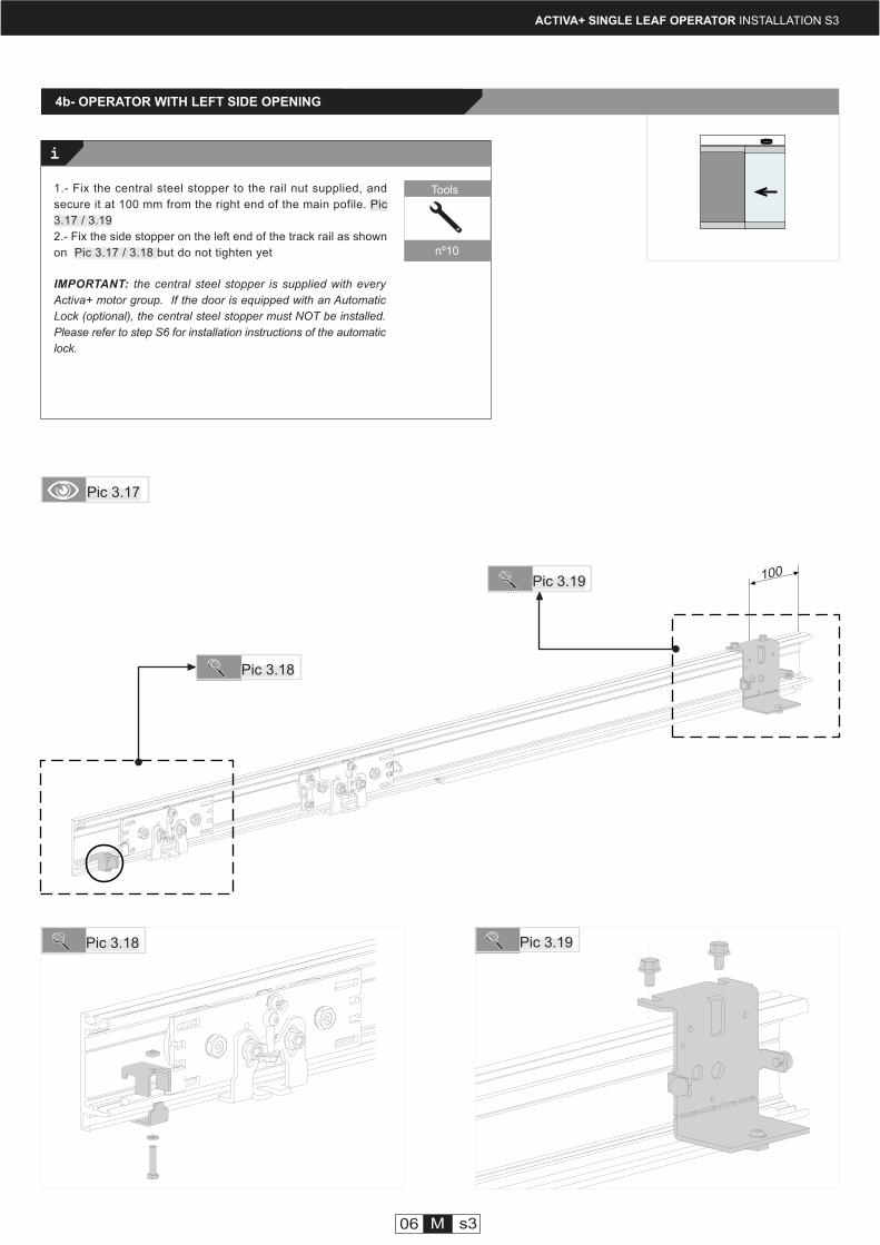
IMPORTANT: the central steel stopper is supplied with every
Activa+ motor group. If the door is equipped with an Automatic
Lock (optional), the central steel stopper must NOT be installed.
Please refer to step S6 for installation instructions of the automatic
lock.
ACTIVA+ SINGLE LEAF OPERATOR INSTALLATION S3
Pic 3.17
Pic 3.19
Pic 3.18
06 M s3
Pic 3.18 Pic 3.19
1.- Fix the central steel stopper to the rail nut supplied, and
secure it at 100 mm from the right end of the main pofile. Pic
3.17 / 3.19
2.- Fix the side stopper on the left end of the track rail as shown
on Pic 3.17 / 3.18 but do not tighten yet
4b- OPERATOR WITH LEFT SIDE OPENING
Ref.
* BRCVLT
* KEGV15LT
i
GV
Ref.
DTMJOVL101EN - v1 - ENGLISH ACTIVA+ SINGLE SLIDE OPERATOR INSTALLATION S4
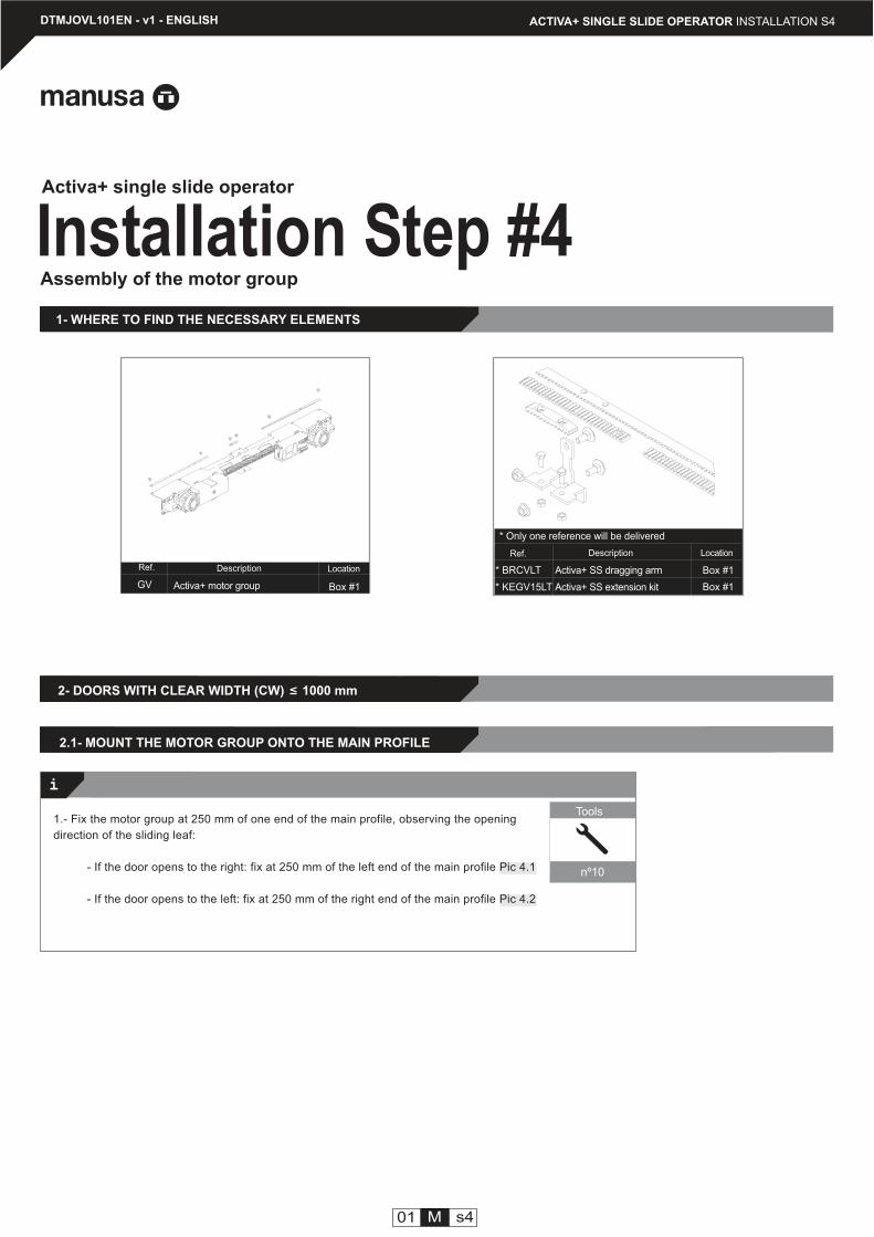
Description
Activa+ motor group
Description Location
Box #1
Box #1
Location
1- WHERE TO FIND THE NECESSARY ELEMENTS
Assembly of the motor group
01 M s4
Box #1
* Only one reference will be delivered
Tools
nº10
2.1- MOUNT THE MOTOR GROUP ONTO THE MAIN PROFILE
Installation Step #4Activa+ single slide operator
Activa+ SS dragging arm
Activa+ SS extension kit
2- DOORS WITH CLEAR WIDTH (CW) 1000 mm
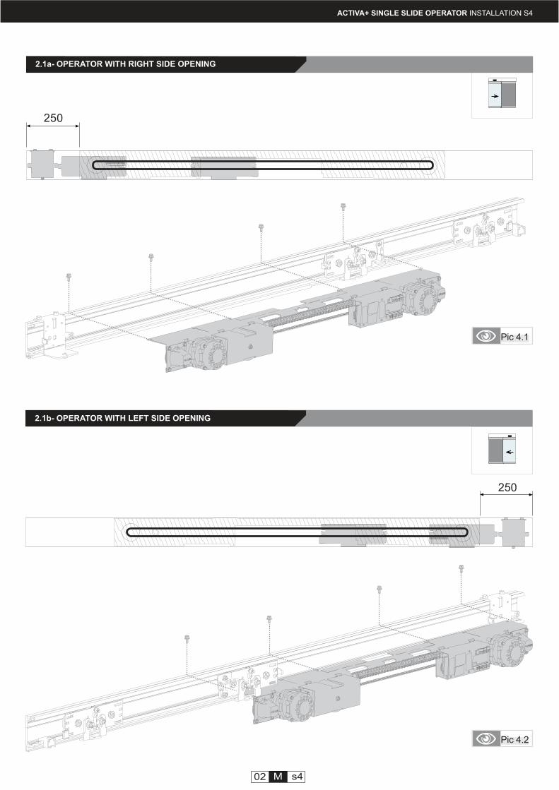
1.- Fix the motor group at 250 mm of one end of the main profile, observing the opening
direction of the sliding leaf:
- If the door opens to the right: fix at 250 mm of the left end of the main profile Pic 4.1
- If the door opens to the left: fix at 250 mm of the right end of the main profile Pic 4.2
<
manusa
manusa
250
250
02 M s4
Pic 4.1
Pic 4.2
ACTIVA+ SINGLE SLIDE OPERATOR INSTALLATION S4
2.1a- OPERATOR WITH RIGHT SIDE OPENING
2.1b- OPERATOR WITH LEFT SIDE OPENING
i
manusa
manusa
ACTIVA+ SINGLE SLIDE OPERATOR INSTALLATION S4
Tools
nº3
Pic 4.3 Pic 4.4
03 M s4
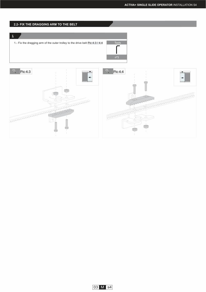
2.2- FIX THE DRAGGING ARM TO THE BELT
1.- Fix the dragging arm of the outer trolley to the drive belt Pic 4.3 / 4.4
i
i
ACTIVA+ SINGLE SLIDE OPERATOR INSTALLATION S4
04 M s4
Pic 4.5
Tools
Saw
Tools
nº10
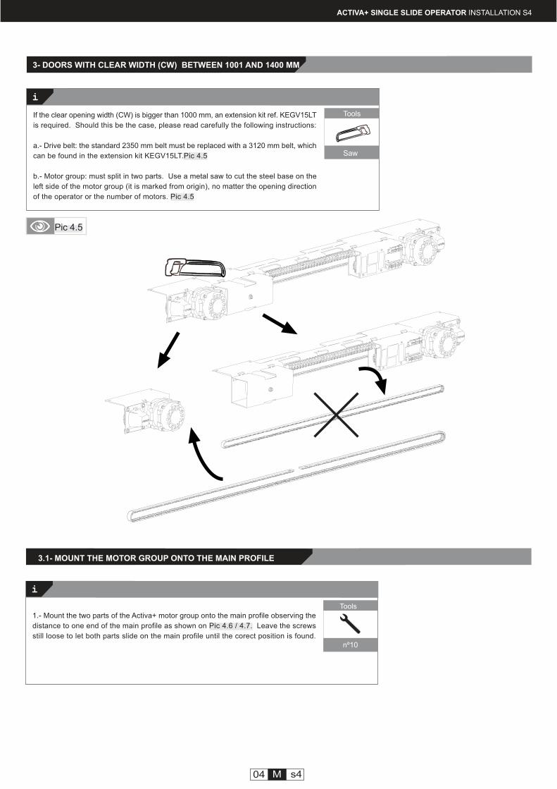
3- DOORS WITH CLEAR WIDTH (CW) BETWEEN 1001 AND 1400 MM
If the clear opening width (CW) is bigger than 1000 mm, an extension kit ref. KEGV15LT
is required. Should this be the case, please read carefully the following instructions:
a.- Drive belt: the standard 2350 mm belt must be replaced with a 3120 mm belt, which
can be found in the extension kit KEGV15LT.Pic 4.5
b.- Motor group: must split in two parts. Use a metal saw to cut the steel base on the
left side of the motor group (it is marked from origin), no matter the opening direction
of the operator or the number of motors. Pic 4.5
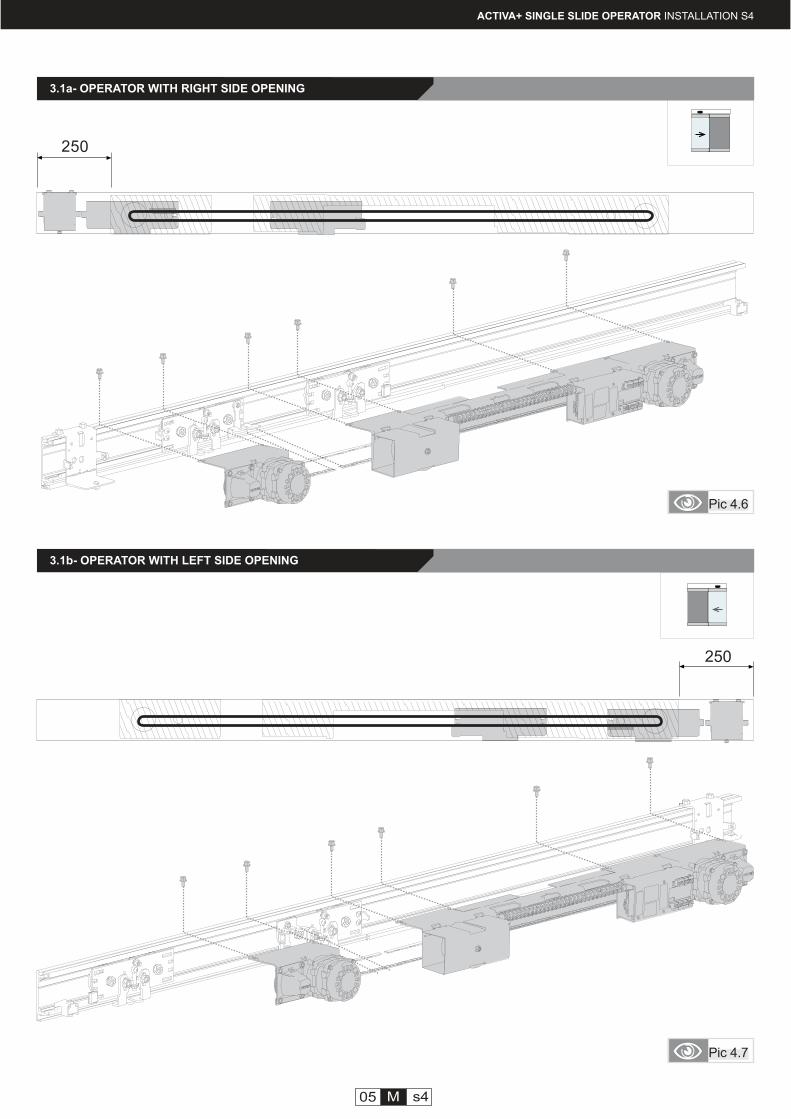
1.- Mount the two parts of the Activa+ motor group onto the main profile observing the
distance to one end of the main profile as shown on Pic 4.6 / 4.7. Leave the screws
still loose to let both parts slide on the main profile until the corect position is found.
3.1- MOUNT THE MOTOR GROUP ONTO THE MAIN PROFILE
manusa
manusa
250
250
ACTIVA+ SINGLE SLIDE OPERATOR INSTALLATION S4
Pic 4.6
Pic 4.7
05 M s4
3.1a- OPERATOR WITH RIGHT SIDE OPENING
3.1b- OPERATOR WITH LEFT SIDE OPENING
i
manusa
manusa
i
manusa manusa
06 M s4
ACTIVA+ SINGLE SLIDE OPERATOR INSTALLATION S4
Tools
nº3
Pic 4.8
Pic 4.10
Pic 4.9
Pic 4.11
Tools
nº10
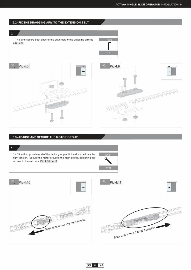
3.2- FIX THE DRAGGING ARM TO THE EXTENSION BELT
1.- Fix and secure both ends of the drive belt to the dragging armPic
4.8 / 4.9.
3.3- ADJUST AND SECURE THE MOTOR GROUP
1.- Slide the opposite end of the motor group until the drive belt has the
right tension. Secure the motor group to the main profile, tightening the
screws to the rail nuts. Pic 4.10 / 4.11
Slide until it has the right tension
Slide until it has the right tension
KSCVCC02
Ref.
PACVCI29
Ref.
JUCI
Ref.
Caja 1GV
Ref.
KSCVCC01
Ref.
PACVCFPS29
Ref.
i
DTMJOVL101EN - v1 - ENGLISH ACTIVA+ SINGLE SLIDE OPERATOR INSTALLATION S5
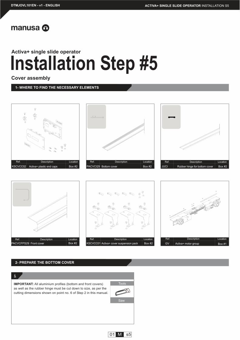
Installation Step #5Activa+ single slide operator
Activa+ plastic end caps Box #2
Description Location
Activa+ cover suspension pack Box #2
Description Location
Bottom cover Box #2
Description Location
Front cover
Description Location
Box #2
Rubber hinge for bottom cover Box #2
Description Location
1- WHERE TO FIND THE NECESSARY ELEMENTS
Cover assembly
2- PREPARE THE BOTTOM COVER
Activa+ motor group
Description Location
Box #1
Tools
Saw
01 M s5
IMPORTANT: All aluminium profiles (bottom and front covers)
as well as the rubber hinge must be cut down to size, as per the
cutting dimensions shown on point no. 6 of Step 2 in this manual.
i
02 M s5
ACTIVA+ SINGLE SLIDE OPERATOR INSTALLATION S5
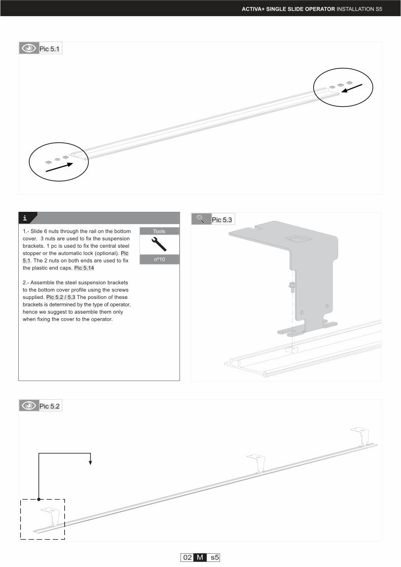
Pic 5.1
Pic 5.2
1.- Slide 6 nuts through the rail on the bottom
cover. 3 nuts are used to fix the suspension
brackets. 1 pc is used to fix the central steel
stopper or the automatic lock (optional). Pic
5.1. The 2 nuts on both ends are used to fix
the plastic end caps. Pic 5.14
2.- Assemble the steel suspension brackets
to the bottom cover profile using the screws
supplied. Pic 5.2 / 5.3 The position of these
brackets is determined by the type of operator,
hence we suggest to assemble them only
when fixing the cover to the operator.
Pic 5.3
Tools
nº10
i
ACTIVA+ SINGLE SLIDE OPERATOR INSTALLATION S5
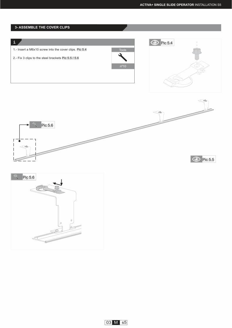
Pic 5.4
1.- Insert a M6x10 screw into the cover clips. Pic 5.4
2.- Fix 3 clips to the steel brackets Pic 5.5 / 5.6
3- ASSEMBLE THE COVER CLIPS
03 M s5
Fig 5.6Pic 5.6
Pic 5.6
Pic 5.5
Tools
nº10
i
manusa
ACTIVA+ SINGLE SLIDE OPERATOR INSTALLATION S5
Pic 5.7
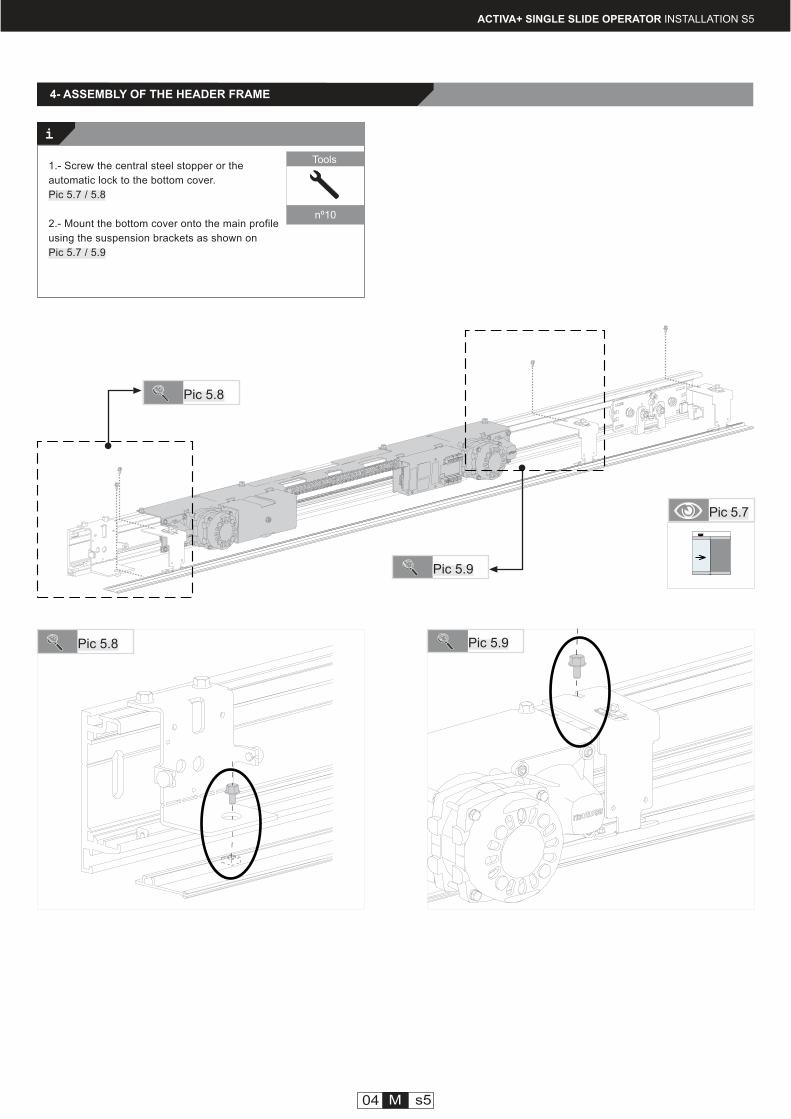
1.- Screw the central steel stopper or the
automatic lock to the bottom cover.
Pic 5.7 / 5.8
2.- Mount the bottom cover onto the main profile
using the suspension brackets as shown on
Pic 5.7 / 5.9
Tools
nº10
Pic 5.8
04 M s5
Pic 5.8 Pic 5.9
Pic 5.9
4- ASSEMBLY OF THE HEADER FRAME
manusa
i
ACTIVA+ SINGLE SLIDE OPERATOR INSTALLATION S5
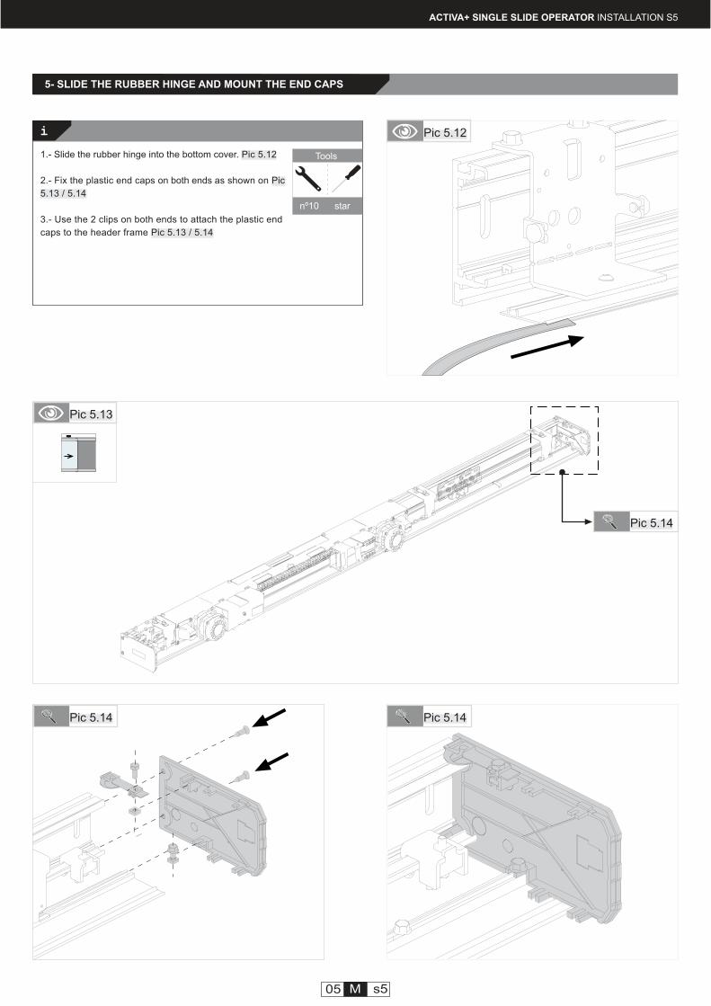
1.- Slide the rubber hinge into the bottom cover. Pic 5.12
2.- Fix the plastic end caps on both ends as shown on Pic
5.13 / 5.14
3.- Use the 2 clips on both ends to attach the plastic end
caps to the header frame Pic 5.13 / 5.14
Pic 5.13
Pic 5.14
Pic 5.12
Tools
nº10 star
Pic 5.14 Pic 5.14
05 M s5
5- SLIDE THE RUBBER HINGE AND MOUNT THE END CAPS
i
manusa
ACTIVA+ SINGLE SLIDE OPERATOR INSTALLATION S5
06 M s5
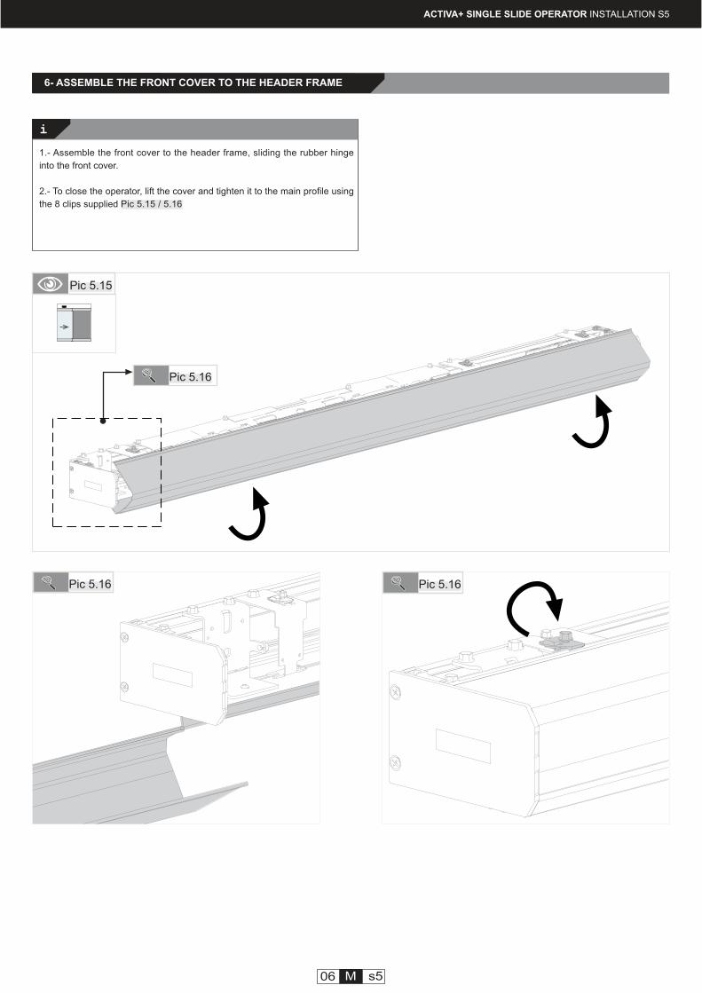
1.- Assemble the front cover to the header frame, sliding the rubber hinge
into the front cover.
2.- To close the operator, lift the cover and tighten it to the main profile using
the 8 clips supplied Pic 5.15 / 5.16
Pic 5.15
Pic 5.16
Pic 5.16 Pic 5.16
6- ASSEMBLE THE FRONT COVER TO THE HEADER FRAME
CJGV03
Ref.
i
i
manusa
DTMJOVL101EN - v1 - ENGLISH ACTIVA+ SINGLE SLIDE OPERATOR INSTALLATION S6
1- WHERE TO FIND THE NECESSARY ELEMENTS
Installation Step #6Activa+ single slide operator
OPT
2- BEFORE INSTALLING THE AUTOMATIC LOCK
Automatic lock CJGV03
Tools
nº10
01 M s6
Activa+ automatic lock
Description Location
Box #1
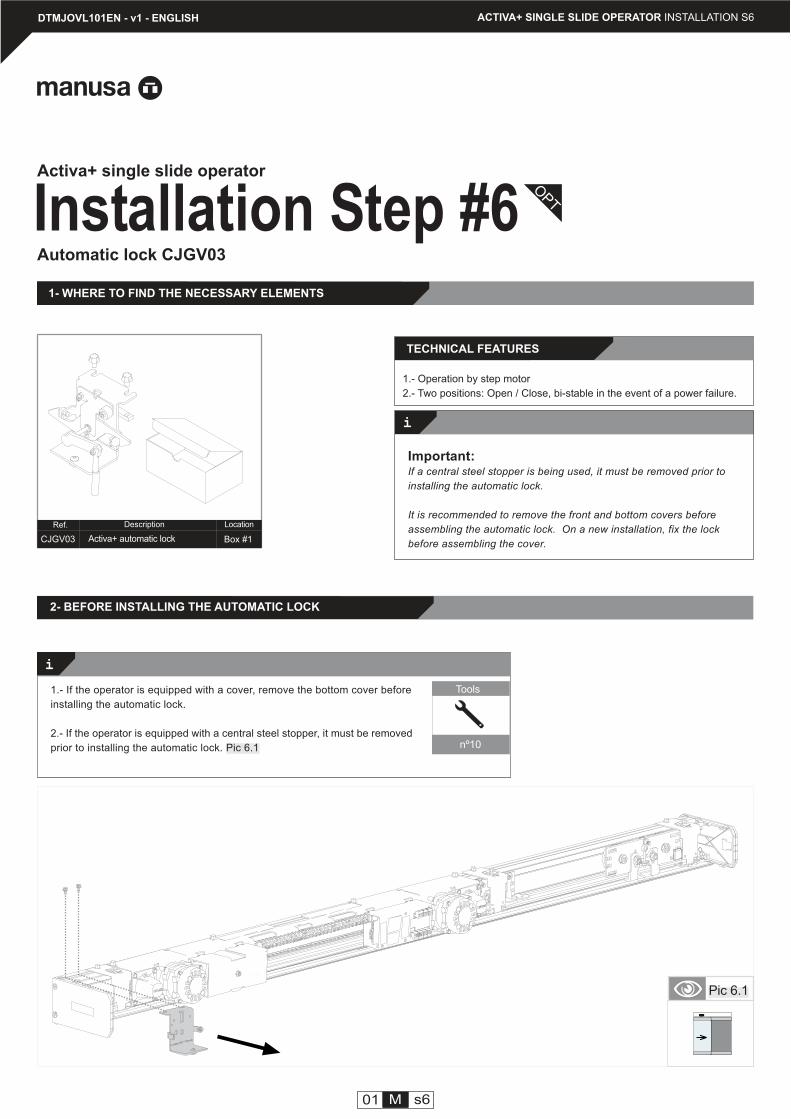
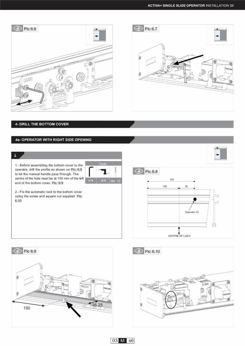
1.- If the operator is equipped with a cover, remove the bottom cover before
installing the automatic lock.
2.- If the operator is equipped with a central steel stopper, it must be removed
prior to installing the automatic lock. Pic 6.1
Important:If a central steel stopper is being used, it must be removed prior to
installing the automatic lock.
It is recommended to remove the front and bottom covers before
assembling the automatic lock. On a new installation, fix the lock
before assembling the cover.
TECHNICAL FEATURES
1.- Operation by step motor
2.- Two positions: Open / Close, bi-stable in the event of a power failure.
Pic 6.1
manusa manusa
3 mm100 mm
3 mm100 mm
i
i
4- INSTALL AND CENTRE THE AUTOMATIC LOCK
manusa
02 M s6
ACTIVA+ SINGLE SLIDE OPERATOR INSTALLATION S6
3- INSTALL THE AUTOMATIC LOCK
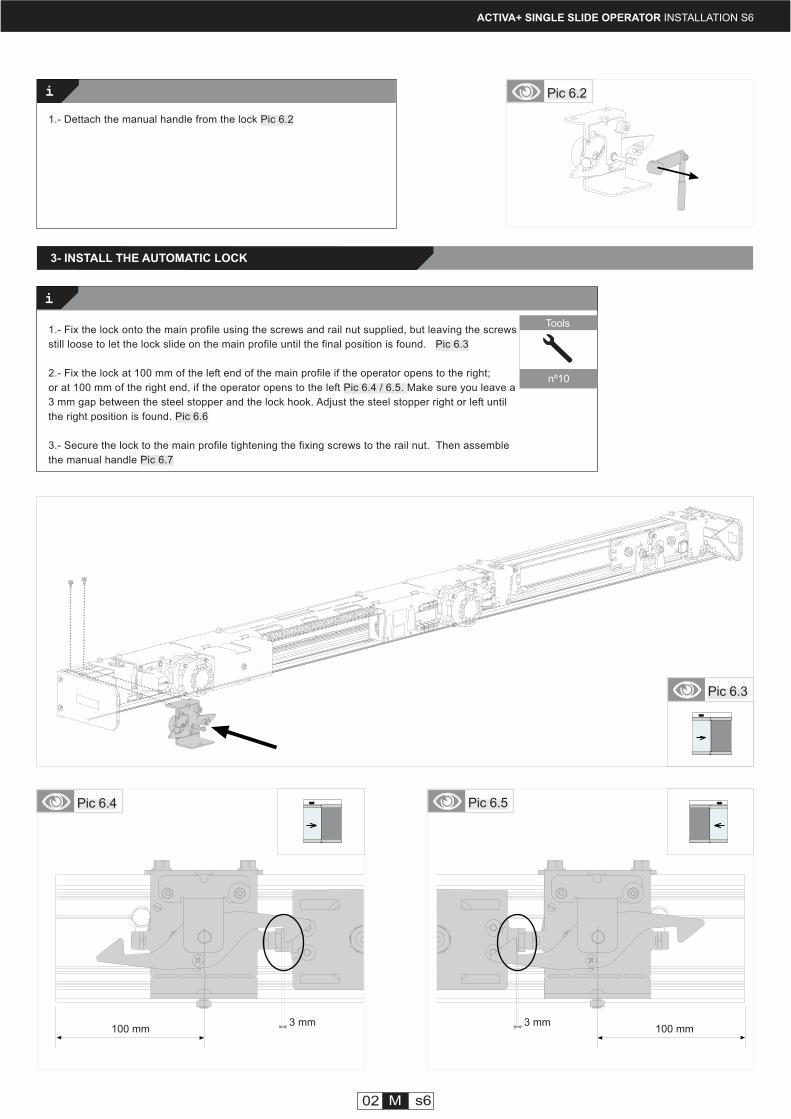
1.- Dettach the manual handle from the lock Pic 6.2
Pic 6.2
Pic 6.5Pic 6.4
Pic 6.3
Tools
nº10
1.- Fix the lock onto the main profile using the screws and rail nut supplied, but leaving the screws
still loose to let the lock slide on the main profile until the final position is found. Pic 6.3
2.- Fix the lock at 100 mm of the left end of the main profile if the operator opens to the right;
or at 100 mm of the right end, if the operator opens to the left Pic 6.4 / 6.5. Make sure you leave a
3 mm gap between the steel stopper and the lock hook. Adjust the steel stopper right or left until
the right position is found. Pic 6.6
3.- Secure the lock to the main profile tightening the fixing screws to the rail nut. Then assemble
the manual handle Pic 6.7
i
manusa
ACTIVA+ SINGLE SLIDE OPERATOR INSTALLATION S6
Pic 6.15
Pic 6.16
Pic 6.15 Pic 6.16
05 M s6
Pic 6.14
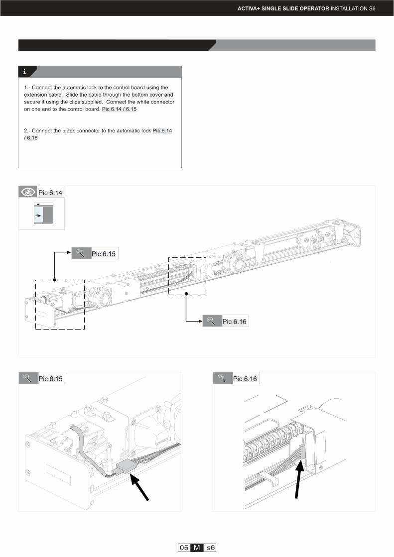
1.- Connect the automatic lock to the control board using the
extension cable. Slide the cable through the bottom cover and
secure it using the clips supplied. Connect the white connector
on one end to the control board. Pic 6.14 / 6.15
2.- Connect the black connector to the automatic lock Pic 6.14
/ 6.16
KSCVPC01
Ref.
- - - - - - -
Ref.
i
DTMJOVL101EN - v1 - ENGLISH ACTIVA+ SINGLE SLIDE OPERATOR - INSTALLATION MANUAL S7
Fixing the operator to the wall
Installation Step #7Activa+ single slide operator
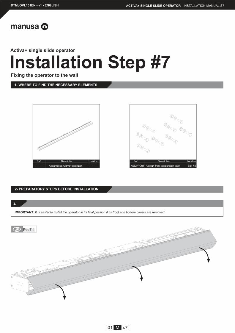
1- WHERE TO FIND THE NECESSARY ELEMENTS
01 M s7
Activa+ front suspension pack Box #2
Description Location
Assemblied Activa+ operator - - - - - - -
Description Location
Pic 7.1
IMPORTANT: It is easier to install the operator in its final position if its front and bottom covers are removed.
2- PREPARATORY STEPS BEFORE INSTALLATION
i
25 25= == =
50 100
ACTIVA+ SINGLE SLIDE OPERATOR - INSTALLATION MANUAL S7
Operator
02 M s7
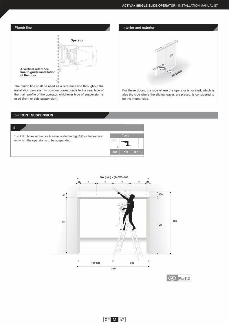
Plumb line
A vertical referenceline to guide installationof the door.
The plumb line shall be used as a reference line throughout the
installation process. Its position corresponds to the rear face of
the main profile of the operator, whichever type of suspension is
used (front or side suspension).
Interior and exterior
For these doors, the side where the operator is located, which is
also the side where the sliding leaves are placed, is considered to
be the interior side.
INTERIOREXTERIOR
Pic 7.2
3- FRONT SUSPENSION
lead
Tools
drill dia 10
CW
1.- Drill 5 holes at the positions indicated in Fig. 7.2, in the surface
on which the operator is to be suspended.
OW (min) = (2xCW)+100
CH
OHCH
FW left
HW
20
50 50
44
03 M s7
ACTIVA+ SINGLE SLIDE OPERATOR - INSTALLATION MANUAL S7
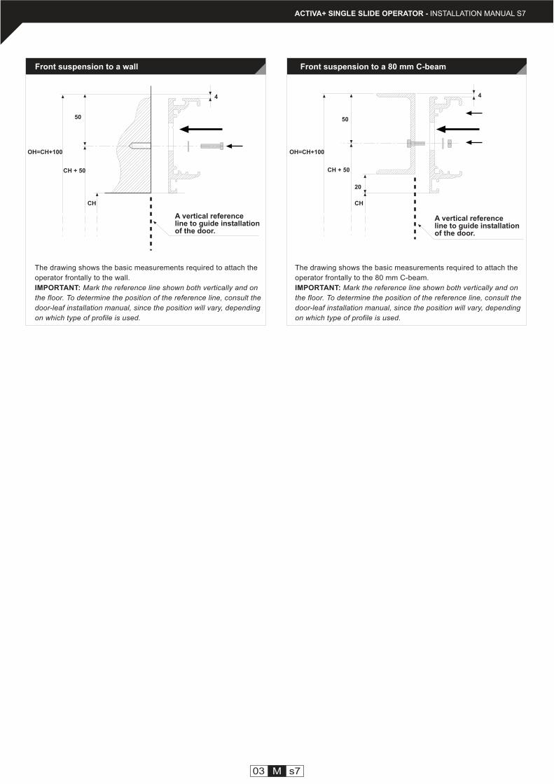
Front suspension to a wall
A vertical referenceline to guide installationof the door.
A vertical referenceline to guide installationof the door.
Front suspension to a 80 mm C-beam
The drawing shows the basic measurements required to attach the
operator frontally to the 80 mm C-beam.
IMPORTANT: Mark the reference line shown both vertically and on
the floor. To determine the position of the reference line, consult the
door-leaf installation manual, since the position will vary, depending
on which type of profile is used.
The drawing shows the basic measurements required to attach the
operator frontally to the wall.
IMPORTANT: Mark the reference line shown both vertically and on
the floor. To determine the position of the reference line, consult the
door-leaf installation manual, since the position will vary, depending
on which type of profile is used.
CH + 50
CH
OH=CH+100
CH
OH=CH+100
CH + 50

Edif. TESTA-10, 4ºAvda. Vía augusta, 71-7308174 Sant Gugat del VallésBarcelona - EspañaTel. +34 902 321 400Fax +34 902 321 450
Polígono Industrial Km. 1,243800 Valls - Tarragona (España)Tel.+34 902 321 700Fax+34 902 321 750
www.manusa.com
NOTE: The technical specifications described in this manual are given for information purposesonly, and do not represent any contractual obligation for Manusa.
Manusa reserves the right to modify in any moment and without prior notice the technicalspecifications displayed in this manual, whenever it is considered to improve the product.
Last revision: May 2006
HEAD OFFICE FACTORY