installation manual d500 - canam-bâtiments · this manual is intended to serve as a basic guide...
TRANSCRIPT

INSTALLATION MANUAL
D500
(couverture)

This manual is intended to serve as a basic guide for the installation of Canam’s Hambro D500™ composite floor system and must be used in combination with the installation drawings that have been issued for construction and provided by your Hambro® supplier. Please contact the supplier should you come across any contradictions or ambiguities in these documents.
The execution of the instructions contained in this manual is the responsibility of the user and must be performed in compliance with current building codes and safety standards.
(page intérieure de la couverture)

TABLE OF CONTENTSOVERVIEW .......................................................................................................................................................................................6HAMBRO D500 COMPOSITE FLOOR SYSTEM .......................................................................................................................10HANDLING AND STORAGE ........................................................................................................................................................12INSTALLATION ..............................................................................................................................................................................14TYPES OF ROLLBARS AND ACCESSORIES ............................................................................................................................22INSTALLATION OF THE FORMWORK SYSTEM AND TEMPORARY BRIDGING ..............................................................28CONCRETING STAGE...................................................................................................................................................................34REMOVAL OF PLYWOOD FORMS ..............................................................................................................................................40
5 B: 14-2637 Canam
Manuel de montage Hambro - ANGLAIS14-2637 Canam Manuel de Montage (mise a jour) EN v
100% 100%5.5” x 2.8545”
Cassio Otto Sophie NadeauStéphane Patry
August 7, 2014 1:12 PM

Canam is fully committed to ensuring risk management and safety on its construction sites, and provides its customers with reference documents and tools to ensure that operations are as safe as possible and to increase project efficiency.Contact your Canam project manager for customized support.
5
CANAM
La sa
nté et sécurité
c’est
l’affairede tous !
CANAM
Healt
h and safetyis
everyone’s
concern!
CANAM
Salud
et seguridad
es
un asuntode todos !

OVERVIEW


9
8
OVERVIEW1. Welded wire mesh draped over joists.2. Concrete slab.3. Wall supporting the joists.4. Joist shoe.5. Cold-rolled top chord “ ” portion embedded 1½ in. (38 mm) in the concrete slab to achieve composite action. 6. Rollbar® clips for temporary bottom chord bridging. 7. Rollbars (rotated into a locked position in the joist) to support plywood forms.8. Rollbar handle.9. Slots in top chord to support Rollbars (chord cut for drawing clarity).10. Reusable 4 ft. x 8 ft. (1,220 mm x 2,440 mm) plywood forms. 11. Minimum width of plywood forms is 1 ft. (305 mm), cut parallel to the grain direction.12. Flange hanger (FH, MH).13. Interior supports.Note: Plywood forms are removed after rotating and removing the Rollbars.
2 1
3 11
10
12 4
6 5
9
8 7
13

9
OVERVIEW1. Welded wire mesh draped over joists.2. Concrete slab.3. Wall supporting the joists.4. Joist shoe.5. Cold-rolled top chord “ ” portion embedded 1½ in. (38 mm) in the concrete slab to achieve composite action. 6. Rollbar® clips for temporary bottom chord bridging. 7. Rollbars (rotated into a locked position in the joist) to support plywood forms.8. Rollbar handle.9. Slots in top chord to support Rollbars (chord cut for drawing clarity).10. Reusable 4 ft. x 8 ft. (1,220 mm x 2,440 mm) plywood forms. 11. Minimum width of plywood forms is 1 ft. (305 mm), cut parallel to the grain direction.12. Flange hanger (FH, MH).13. Interior supports.Note: Plywood forms are removed after rotating and removing the Rollbars.

HAMBRO D500 COMPOSITE FLOOR SYSTEM
11
HAMBRO D500 COMPOSITE FLOOR SYSTEMGENERAL NOTES
Canam is a material supplier only, and as such, does not perform work on site and is not responsible for the field work, including installation. This manual is provided as an aid to installation. Deviation from the installation manual shall release Canam from all liability relating to the material. Canam assumes no liability for installation or handling of the material on the jobsite. Site conditions may differ. Consult the engineer of record for approval of and direction on the installation procedures.
Any changes to the issued for construction plans that may be required due to jobsite conditions must be reviewed and accepted by Canam.
The nominal spacing of Hambro D500 composite joists is 4 ft.-1¼ in. (1,251 mm). Refer to the installation drawings specific to each project.
The Hambro D500 composite floor system must be installed in compliance with the issued for construction drawings and the instructions in the Canam installation manual.

HANDLING AND STORAGEHOISTINGWhen the joists are hoisted using a crane, the steel choker must be placed at third points along the top chord. Never attach the cables to the web members.
STORAGEHambro joists must be stored lengthwise on a level surface. To prevent damage, joists should not be stacked.
DAMAGED JOISTSCare should be taken at all times to avoid damaging the joists through careless handling during unloading, storage and/or installation. Note that damaged joists may impair the performance and safety of the system.
All damage must be reported to the project manager who will make the necessary recommendations.
DO NOT MAKE FIELD REPAIRS TO DAMAGED HAMBRO JOISTS WITHOUT WRITTEN AUTHORIZATION FROM THE CANAM ENGINEER OF RECORD.
13
HANDLING AND STORAGE
= = =

HANDLING AND STORAGEHOISTINGWhen the joists are hoisted using a crane, the steel choker must be placed at third points along the top chord. Never attach the cables to the web members.
STORAGEHambro joists must be stored lengthwise on a level surface. To prevent damage, joists should not be stacked.
DAMAGED JOISTSCare should be taken at all times to avoid damaging the joists through careless handling during unloading, storage and/or installation. Note that damaged joists may impair the performance and safety of the system.
All damage must be reported to the project manager who will make the necessary recommendations.
DO NOT MAKE FIELD REPAIRS TO DAMAGED HAMBRO JOISTS WITHOUT WRITTEN AUTHORIZATION FROM THE CANAM ENGINEER OF RECORD.
13

INSTALLATION
1 - POSITIONING OF JOISTSThe joists are placed on the walls or beams and positioned in compliance with the shop drawings issued for construction by Canam. The anchorage of joist ends are also shown on the Canam erection drawings.
2 - ROLLBARSThe Rollbars are designed to support the plywood forms, concrete and a 50 psf (2.4 kPa) construction load. When rotated and locked into the notches in the top chord, the Rollbars lock the joists in place while providing lateral and torsional stability.
== =
15

3 - PLYWOOD FORMSTogether, the plywood and the Rollbars form a rigid diaphragm during construction, providing a safe platform for workers. The Hambro system uses standard 4 ft. x 8 ft. x ½ in.* (1,200 mm x 2,400 mm x 13 mm*) plywood sheets.* Subject to change: review erection drawings.
4 - SHEETS OF MESHWelded wire mesh serves as the standard catenary for the slab. Standard 8 ft. x 20 ft. (2,400 mm x 6,100 mm) sheets of mesh are easily placed over the top chords of the Hambro joists. The top chord acts as a highchair. (Consult the installation drawings issued for construction for quantities, if required.)
5 - TEMPORARY BRIDGINGBottom chords are fabricated with clips to accommodate Rollbars for temporary bridging during the pouring stage. Generally, no permanent bridging neither shoring are required unless specifically noted. (Consult the installation drawings for details.)
17
16

5 - TEMPORARY BRIDGINGBottom chords are fabricated with clips to accommodate Rollbars for temporary bridging during the pouring stage. Generally, no permanent bridging neither shoring are required unless specifically noted. (Consult the installation drawings for details.)
17

19
3½ in. (90 mm) minimum bearing for 4 in. (102 mm) shoe
2½ in. (65 mm) minimum bearing for 3 in. (76 mm) shoe
3½ in. (90 mm) minimum bearing for 4 in. (102 mm) shoe
Bearing on ICF wallSTANDARD JOIST SHOE BEARINGThe standard joist shoe bearing is determined according to the load-bearing elements. Refer to the issued for construction installation drawings for sectional views and details.
3½ in. (90 mm) minimum bearing for 4 in. (102 mm) shoe
Bearing on concrete, masonry or wood walls Bearing on steel beams or light gauge walls
18

19
3½ in. (90 mm) minimum bearing for 4 in. (102 mm) shoe
2½ in. (65 mm) minimum bearing for 3 in. (76 mm) shoe 3½ in. (90 mm) minimum bearing for 4 in. (102 mm) shoe
Bearing on concrete, masonry or wood walls Bearing on steel beams or light gauge walls

SPACING FOR ROLLBARSIn order to support the forms adequately, the Rollbars should be spaced at the intervals indicated on the installation drawings. There must be a minimum of one (1) Rollbar at 7 in. (178 mm) from the end of each plywood form and for each sheet joint, there must be at least four (4) interior supports for a standard joist spacing of 4 ft.-1¼ in. (1,251 mm).
Whenever possible, it is recommended that Rollbars be staggered from bay to bay so that only one Rollbar end is in each slot. This will simplify the stripping procedure. This does not apply to temporary bottom chord bridging or to the first Rollbar nearest the load-bearing wall or beam.
21
20
THICKENED SLABSHanger plates allow for the addition of an increased layer of thickness to the slab (see the table below for thickness).
Perforated plate
inch mm
2 51
3 76
5 127
6 152
Note: Refer to the details provided on the installation drawings for the total thickness of the slab and the location of the added layers.

21
THICKENED SLABSHanger plates allow for the addition of an increased layer of thickness to the slab (see the table below for thickness).
Perforated plate
inch mm
2 51
3 76
5 127
6 152
Note: Refer to the details provided on the installation drawings for the total thickness of the slab and the location of the added layers.

TYPES OF ROLLBARS AND ACCESSORIES
STANDARD ROLLBAR TELESCOPIC ROLLBAR No. 4
23
5 ft.-1¼ in. (1,556 mm) - RB2 (orange)
4 ft.-1¼ in. (1,251 mm) - RB1 (grey primer)
2 ft.-1¼ in. (641 mm) - RB12 (pink) 1 ft.-11½ in. (597 mm) to 3 ft.-1 in. (940 mm) - RB4 (yellow)

STANDARD ROLLBAR TELESCOPIC ROLLBAR No. 4
23
5 ft.-1¼ in. (1,556 mm) - RB2 (orange)
4 ft.-1¼ in. (1,251 mm) - RB1 (grey primer)
2 ft.-1¼ in. (641 mm) - RB12 (pink) 1 ft.-11½ in. (597 mm) to 3 ft.-1 in. (940 mm) - RB4 (yellow)

INTERIOR SUPPORT ROLLBAR RACK
TELESCOPIC ROLLBAR NO. 5 EDGE-FORMING ROLLBAR
RB9
25
24
3 ft.-0½ in. (928 mm) to 4 ft.-9 in. (1,448 mm) - RB5 (blue)
1 ft.-3¼ in. (387 mm) - RB13 (grey primer)
1 ft.-9 in. (533 mm)
2 ft.-1 in. (635 mm) - RB8CL
CL
2 in. (51 mm)
2 in.
(51 mm)
Used to support plywood joints.
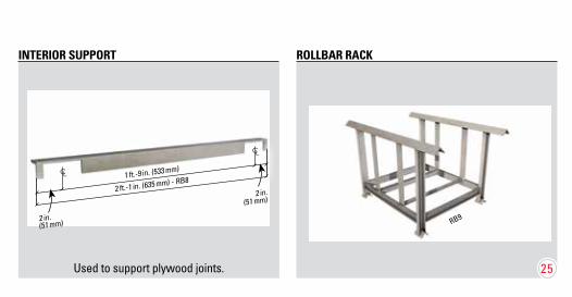
INTERIOR SUPPORT ROLLBAR RACK
RB9
25
1 ft.-9 in. (533 mm)
2 ft.-1 in. (635 mm) - RB8CL
CL
2 in. (51 mm)
2 in.
(51 mm)
Used to support plywood joints.

Used with walls made of light gauge steel stud, concrete, wood, masonry or with a beam.
Only used on an insulated concrete wall unless specified otherwise on the installation drawings.
MASONRY HANGER (MH)
FLANGE HANGER (FH)
FH type flange hanger
Steel structure, light gauge, concrete or masonry walls
MH type masonry hanger
ICF wall
26
27
3 in.(76 mm)
4½ in.(114 mm)

Only used on an insulated concrete wall unless specified otherwise on the installation drawings.
MASONRY HANGER (MH)
MH type masonry hanger
ICF wall
27
4½ in.(114 mm)

The line of temporary cross bridging is indicated by “ “ on the installation drawings issued by Canam
INSTALLATION OF THE FORMWORK SYSTEM AND TEMPORARY BRIDGING
INSTALLATION OF THE FORMWORK SYSTEM AND TEMPORARY BRIDGINGSTANDARD SPACING OF 2 ft.-1¼ in. (641 mm), 4 ft.-1¼ in. (1,251 mm) OR 5 ft.-1¼ in. (1,556 mm)
TEMPORARY BRIDGINGS BETWEEN TWO JOISTS
29The line of temporary bridging is indicated by “ ------ “ on the installation drawings issued by Canam.

The line of temporary cross bridging is indicated by “ “ on the installation drawings issued by Canam
INSTALLATION OF THE FORMWORK SYSTEM AND TEMPORARY BRIDGINGSTANDARD SPACING OF 2 ft.-1¼ in. (641 mm), 4 ft.-1¼ in. (1,251 mm) OR 5 ft.-1¼ in. (1,556 mm)
TEMPORARY BRIDGINGS BETWEEN TWO JOISTS
29The line of temporary bridging is indicated by “ ------ “ on the installation drawings issued by Canam.

This system is applicable to cantilever slabs ≤ 1 ft.-2¾ in. (375 mm). For cantilever slabs > 1 ft.-2¾ in. (375 mm), the system must be stabilized; refer to the recommendations of the consulting engineer.
A sheet of polythene can be placed directly over the plywood in order to protect it and facilitate removal afterwards. The polythene should never cover the joist or the top chord. No materials whatsoever should cover the top chord so as not to impact the joist’s composite action.
NON-STANDARD SPACING
TEMPORARY CROSS BRIDGINGS BETWEEN TWO JOISTS
FORMS ON CANTILEVER SLABS FORMWORK SYSTEM (If polythene is used.)
31
30The line of temporary cross bridging is indicated by “ “ on the installation drawings issued by Canam.

This system is applicable to cantilever slabs ≤ 1 ft.-2¾ in. (375 mm). For cantilever slabs > 1 ft.-2¾ in. (375 mm), the system must be stabilized; refer to the recommendations of the consulting engineer.
A sheet of polythene can be placed directly over the plywood in order to protect it and facilitate removal afterwards. The polythene should never cover the joist or the top chord. No materials whatsoever should cover the top chord so as not to impact the joist’s composite action.
FORMS ON CANTILEVER SLABS FORMWORK SYSTEM (If polythene is used.)
31

PRECAUTIONS1. Before any loads are applied or the forms are put in place, at least three (3) joists must be installed
with all the required Rollbars in order to ensure the structural capacity of the Hambro joists.
2. Full sheets of plywood are recommended. When shorter pieces are used, make sure that they are adequately supported and do not present a safety risk for workers and construction loads.
3. Bundles of plywood should be placed on supporting walls or beams, never on the joist system. The system is not designed for this purpose and can compromise worksite safety.
33
Do not overload the slab or joists during construction with materials such as palettes of cement blocks, dry stone walls, sand, etc.
Never use pieces of plywood to complete the forms as this could compromise worksite safety.
32

PRECAUTIONS1. Before any loads are applied or the forms are put in place, at least three (3) joists must be installed
with all the required Rollbars in order to ensure the structural capacity of the Hambro joists.
2. Full sheets of plywood are recommended. When shorter pieces are used, make sure that they are adequately supported and do not present a safety risk for workers and construction loads.
3. Bundles of plywood should be placed on supporting walls or beams, never on the joist system. The system is not designed for this purpose and can compromise worksite safety.
33

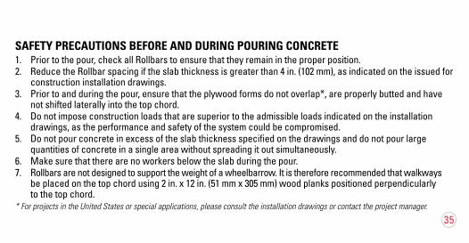
SAFETY PRECAUTIONS BEFORE AND DURING POURING CONCRETE1. Prior to the pour, check all Rollbars to ensure that they remain in the proper position.2. Reduce the Rollbar spacing if the slab thickness is greater than 4 in. (102 mm), as indicated on the issued for
construction installation drawings.3. Prior to and during the pour, ensure that the plywood forms do not overlap*, are properly butted and have
not shifted laterally into the top chord. 4. Do not impose construction loads that are superior to the admissible loads indicated on the installation
drawings, as the performance and safety of the system could be compromised.5. Do not pour concrete in excess of the slab thickness specified on the drawings and do not pour large
quantities of concrete in a single area without spreading it out simultaneously.6. Make sure that there are no workers below the slab during the pour. 7. Rollbars are not designed to support the weight of a wheelbarrow. It is therefore recommended that walkways
be placed on the top chord using 2 in. x 12 in. (51 mm x 305 mm) wood planks positioned perpendicularly to the top chord.
* For projects in the United States or special applications, please consult the installation drawings or contact the project manager.
CONCRETE STAGE
35
SAFETY PRECAUTIONS BEFORE AND DURING POURING CONCRETE1. Prior to the pour, check all Rollbars to ensure that they remain in the proper position.2. Reduce the Rollbar spacing if the slab thickness is greater than 4 in. (102 mm), as indicated on the issued for
construction installation drawings.3. Prior to and during the pour, ensure that the plywood forms do not overlap*, are properly butted and have
not shifted laterally into the top chord. 4. Do not impose construction loads that are superior to the admissible loads indicated on the installation
drawings, as the performance and safety of the system could be compromised.5. Do not pour concrete in excess of the slab thickness specified on the drawings and do not pour large
quantities of concrete in a single area without spreading it out simultaneously.6. Make sure that there are no workers below the slab during the pour. 7. Rollbars are not designed to support the weight of a wheelbarrow. It is therefore recommended that walkways
be placed on the top chord using 2 in. x 12 in. (51 mm x 305 mm) wood planks positioned perpendicularly to the top chord.
* For projects in the United States or special applications, please consult the installation drawings or contact the project manager.
35
PARALLEL CONSTRUCTION JOINTSWhen pouring and finishing a Hambro floor, it is not necessary to complete the entire deck in a single pour. Should it become necessary to stop the pour parallel to the joists, the joint should be midway between the joists, but never less than 6 in. (152 mm) from the top chord.
PERPENDICULAR CONSTRUCTION JOINTSConstruction joints perpendicular to the joists should be made over the load-bearing wall or needle beam but never over the joists as this could counteract the design. The pour must be stopped gradually over the support and the surface of the concrete must be left rough.
The concrete pour should be stopped gradually. The concrete surface must be rough.
45˚
The concrete pour should be stopped gradually above the support. The concrete surface must be rough.
37
36
6 in. (152 mm) min.
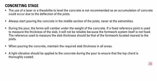
CONCRETING STAGE• The use of a laser or a theodolite to level the concrete is not recommended as an accumulation of concrete
could occur due to the deflection of the joists.
• Always start pouring the concrete in the middle section of the joists, never at the extremities.
• During the pour, the forms will camber under the weight of the concrete. If a fixed reference point is used to measure the thickness of the slab, it will not be reliable because the formwork system itself is not fixed. The reference used to measure the slab thickness should be that of the formwork located nearest to the joists.
• When pouring the concrete, maintain the required slab thickness in all areas.
• A light vibration should be applied to the concrete during the pour to ensure that the top chord is thoroughly coated.

PARALLEL CONSTRUCTION JOINTSWhen pouring and finishing a Hambro floor, it is not necessary to complete the entire deck in a single pour. Should it become necessary to stop the pour parallel to the joists, the joint should be midway between the joists, but never less than 6 in. (152 mm) from the top chord.
PERPENDICULAR CONSTRUCTION JOINTSConstruction joints perpendicular to the joists should be made over the load-bearing wall or needle beam but never over the joists as this could counteract the design. The pour must be stopped gradually over the support and the surface of the concrete must be left rough.
The concrete pour should be stopped gradually. The concrete surface must be rough.
45˚
The concrete pour should be stopped gradually above the support. The concrete surface must be rough.
37
6 in. (152 mm) min.

PLACINGWhen placing the concrete, maintain a minimum depth of 1 in. (25 mm) above the top chord for a nominal 2 ¾ in. (70 mm) slab. The joists are fabricated with a positive camber to offset the deflection caused by the weight of the concrete.
FINISHING AND CURINGDuring the curing phase, temperature and moisture conditions must be within the limits specified in standard CAN/CSA A23.3 for projects in Canada, standard ACI-318 for projects in the U.S., and editions that are in force.
The maximum weight of the equipment used to pour and polish the concrete should be less or equal to 600 lb (275 kg), excluding the operator. Validate this reference weight with the Canam engineer. 38


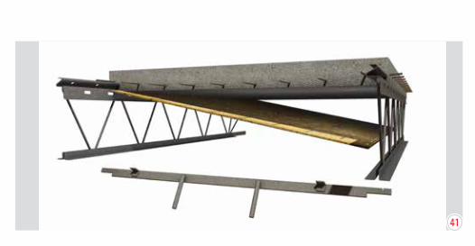
REMOVAL OF PLYWOOD FORMS
41
41

REMOVAL OF PLYWOOD FORMSWhen the concrete attains a cylinder strength of 500 psi (3.5 MPa), the Rollbars and plywood forms can be removed. When the concrete attains a cylinder strength of 1,000 psi (7 MPa), the floor is ready but do not surpass the admissible loads indicated for the specified capacity. Please contact the Canam engineer to validate the admissible loads. (see tables Formwork Removal According to Weather Conditions).
Avoid dropping Rollbars on the slab as this may damage the concrete surface.
Rollbars should be replaced in their respective racks according to type and stored in an area where they can easily be hoisted by crane.
42


44
FORMWORK REMOVAL ACCORDING TO WEATHER CONDITIONSThe following tables present the minimum amount of time required or the minimum compressive strength that the concrete must reach before the formwork can be removed.
* Respecting the standards of the concrete supplier, according to the product’s composition and the pour conditions, and in compliance with the strength-gain curve of the concrete over time.
Normal temperaturebetween 40°F and 80°F
(5°C and 27°C)
Compressive strength
Hours after the pour
Formwork removal 500 psi (3.5 MPa)* 24 hours*
Ready for use 1,000 psi (7 MPa)* 48 hours*

(page intérieure de la couverture-arrière)
45
1. Following 72 hours of heating, the concrete must be kept at a minimum temperature of 25°F (3°C).2. Protection against the cold (insulation or shelter) should be removed gradually to prevent cracking
due to a sudden change in temperature.
Temperature over 80°F (27°C): apply standard CAN/CSA A23.3 for Canada or ACI-318 for the U.S., and editions that are in force.
Winter temperatureunder 40°F (5°C)
Constant temperature Compressive strength
Minimum hours after placement
Removal of plywood forms 500 psi (3.5 MPa) 48 hours with heating
Heating1 after placement and insulation2
Between 50°F and 95°F (10°C and 35°C) 1,000 psi (7 MPa) 72 hours

1-866-506-4000 www.hambro.com
Hambro products are sold in Canada by Canam Group Inc., in the United States by Canam Steel Corporation, or through their respective agents, distributors or representatives in those countries.
© Canam Group Inc., 2003-2014Revised 08/2014
Printed in Canada
(couverture-arrière)