installation manual - golf car catalog.com · installation manual mac roll bar mount mobile audio...
TRANSCRIPT

Installation Manual
MAC
Roll Bar Mount Mobile Audio Console
RMT
Roof Mount Mobile Audio Console

Contents of package for the MAC Audio Console
U-bolts
Parts List
1. U-bolt kit: (2) U-bolts
(2) Rubber pads
(2) Backing plates
(4) Lock nuts
(4) Rubber grommets
(1) Drill bit
2. Wiring kit: (2) Ring terminals
(2) Butt connectors
(1) Fuse holder
(1) 15A fuse
(1) T-tap
(1) Male connector
3. Install kit: (6) Wire ties
(4) Wire tie mounts
Steps for installing the MAC
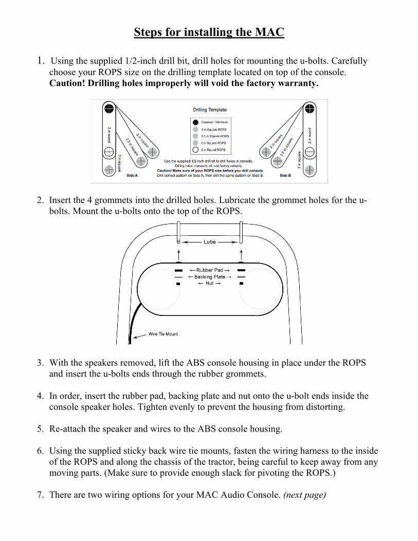
1. Using the supplied 1/2-inch drill bit, drill holes for mounting the u-bolts. Carefully
choose your ROPS size on the drilling template located on top of the console.
Caution! Drilling holes improperly will void the factory warranty.
2. Insert the 4 grommets into the drilled holes. Lubricate the grommet holes for the u-
bolts. Mount the u-bolts onto the top of the ROPS.
3. With the speakers removed, lift the ABS console housing in place under the ROPS
and insert the u-bolts ends through the rubber grommets.
4. In order, insert the rubber pad, backing plate and nut onto the u-bolt ends inside the
console speaker holes. Tighten evenly to prevent the housing from distorting.
5. Re-attach the speaker and wires to the ABS console housing.
6. Using the supplied sticky back wire tie mounts, fasten the wiring harness to the inside
of the ROPS and along the chassis of the tractor, being careful to keep away from any
moving parts. (Make sure to provide enough slack for pivoting the ROPS.)
7. There are two wiring options for your MAC Audio Console. (next page)

Wiring Option 1
STANDARD ACCESSORY POSITION INSTALLATION
Installing this way will only allow the stereo to be turned on if the key is in the
accessory position. This will also always turn the stereo off when the key is in the off
position.
1. With a razor blade, score and then strip away the insulation on the end of the
wiring harness.
2. Attach the green trigger wire to the factory accessory position on the key ignition
switch using the male connector.
3. Using a butt connector, attach a lead wire of the fuse holder to the white power
wire of the MAC.
4. Then attach the other lead wire of the fuse holder to the positive lead on the
battery, using a ring terminal.
5. Install the black wire to the negative lead on the battery using the other ring
terminal.
CAUTION: Install the 15 amp fuse in the fuse holder after the positive and negative
leads are connected to the battery.

Wiring Option 2
CONSTANT POWER INSTALLATION
Installing this way will allow the stereo to play at all times, even if the key is not in the
on position. If the stereo is installed this way, the stereo does have the ability to drain the
battery if the radio is left on for an extended amount of time.
1. With a razor blade score and then strip away the insulation on the end of the wiring
harness.
2. Connect the green wire to the white wire before the butt connector using the t-tap
and male connector.
3. Then connect the white wire to one end of the fuse holder using a butt connector.
4. Install a ring terminal on the other end of the fuse holder and connect it to the
positive lead on the battery.
5. Install a ring terminal on the black wire and connect it to the negative lead on the
battery.
CAUTION: Install the 15 amp fuse in the fuse holder after the positive and negative
leads are connected to the battery.

Contents of package for the RMT Audio Console
Parts List
1. Mount kit: (12) Bolts
(4) Lock Nuts
(4) Gasket Washers
2. Wiring kit: (2) Ring terminals
(2) Butt connectors
(1) Fuse holder
(1) 15A fuse
(1) T-tap
(1) Male connector
3. Install kit: (6) Wire ties
(4) Wire tie mounts

Steps for Installing the RMT
1. Remove the 4 screws from the top of the RMT.
2. Remove the top plate of the RMT. Hold the top plate in the desired location of the
Stereo.
3. Use the plate as a pattern to mark the 4 hole locations.
4. Drill inch holes completely through the top of the roof structure you are mounting
the RMT up to.
Tractor Tunes has provided 3 sizes of bolts in the bolt kit. Because this is a universal
RMT, You will need to determine the proper size for your application.
Always use the supplied sealing washers on the exterior of your top to provide a seal for
the bolts. Take your time to install this product. Installing it properly will ensure years of
listening enjoyment..
Warning! Tractor Tunes will not warranty any installation of this product.
This is an aftermarket product and needs to be installed properly. Failing to drill
the correct size holes, over tightening and not using the provided sealing washers
will cause damage to the RMT and whatever you are bolting it to.

Wiring Option 1
STANDARD ACCESSORY POSITION INSTALLATION
Installing this way will only allow the stereo to be turned on if the key is in the
accessory position. This will also always turn the stereo off when the key is in the off
position.
1. With a razor blade, score and then strip away the insulation on the end of the wiring
harness.
2. Attach the green trigger wire to the factory accessory position on the key ignition
switch using the male connector.
3. Using a butt connector, attach a lead wire of the fuse holder to the white power wire
of the MAC.
4. Then attach the other lead wire of the fuse holder to the positive lead on the battery,
using a ring terminal.
5. Install the black wire to the negative lead on the battery using the other ring terminal.
CAUTION: Install the 15 amp fuse in the fuse holder after the positive and negative
leads are connected to the battery.

Wiring Option 2
CONSTANT POWER INSTALLATION
Installing this way will allow the stereo to play at all times, even if the key is not in the
on position. If the stereo is installed this way, the stereo does have the ability to drain the
battery if the radio is left on for an extended amount of time.
1. With a razor blade score and then strip away the insulation on the end of the wiring
harness.
2. Connect the green wire to the white wire before the butt connector using the t-tap
and male connector.
3. Then connect the white wire to one end of the fuse holder using a butt connector.
4. Install a ring terminal on the other end of the fuse holder and connect it to the
positive lead on the battery.
5. Install a ring terminal on the black wire and connect it to the negative lead on the
battery.
CAUTION: Install the 15 amp fuse in the fuse holder after the positive and negative
leads are connected to the battery.