installation manual - mcss630-usam v0517 - integral audio manual - mcss630... · installation...
TRANSCRIPT

SKILL LEVEL REQUIRED APPLIES TO
INSTALLATION DIFFICULTY
INSTALLATION TIME
3 OUT OF 5
DO-IT-YOURSELF
6-8 HOURS
R57 STANDARD 6 SPEAKER
R57 HIFI/HK
R58 STANDARD 6 SPEAKER
R58 HIFI/HK
R59 STANDARD 6 SPEAKER
R59 HIFI/HK
2007-2009 R56 JCW
OVERVIEW ........................................................................................................................................ 2
BEFORE YOU BEGIN .......................................................................................................................... 2
WHAT’S IN THE BOX - SOUNDSTAGE .................................................................................................. 3
WHAT’S IN THE BOX - SUBWOOFER ................................................................................................... 4
TOOLS YOU WILL NEED ...................................................................................................................... 5
INSTALLATION:A. Prep Vehicle ........................................................................................................................ 6
B. Power & Ground Wiring ........................................................................................................ 7
C. Signal Wiring ....................................................................................................................... 8
D. Amplifier Installation & Speaker wiring............................................................................... 9
E. Soundstage speaker installation ....................................................................................... 11
F. Install the Subwoofer [sub only] ........................................................................................ 14
G. Testing & Recommended Initial Settings .......................................................................... 16
TIPS & TUNING ................................................................................................................................ 18
TROUBLESHOOTING ......................................................................................................................... 18
INSTALLATION GUIDESOUNDSTAGE + SUBWOOFER SYSTEMUNDERSEAT AMP MOUNT (MCSS630SW-USAM) ver. 5/17
BEFO
RE Y
OU B
EGIN
2
• Read this Guide completely BEFORE you begin.
• Disconnect the battery negative terminal while working on the vehicle.• DO NOT PLACE THE KEY FOB in the vehicle with the battery connected and
the seat airbag wiring disconnected. Doing so will set off the airbag light, which must be reset by your dealer.
• ALWAYS check behind panels and components before drilling, cutting, or screwing into any part of a vehicle.
• This guide covers several different vehicle models and options. Some steps only apply to certain installations. Steps images are labeled with a black bar across the top:
- [6SPK ONLY] apply only to vehicles equipped with the standard 6 speaker audio system.
- [HIFI/HK ONLY] apply only to vehicles equipped with the upgraded 10 speaker HIFI and Harmon Kardon audio system. If the vehicle has tweeters in the A-pillar (near the bottom outer corners of the windshield), you have the HIFI or HK systems.
- [SUB ONLY] apply only if you are installing the Integral Audio Subwoofer System
- [RXX ONLY] apply only to the specific model listed.
- If there is no label, the step applies to ALL installations
- Because each kit applies to more than one vehicle, your kit may include extra items.
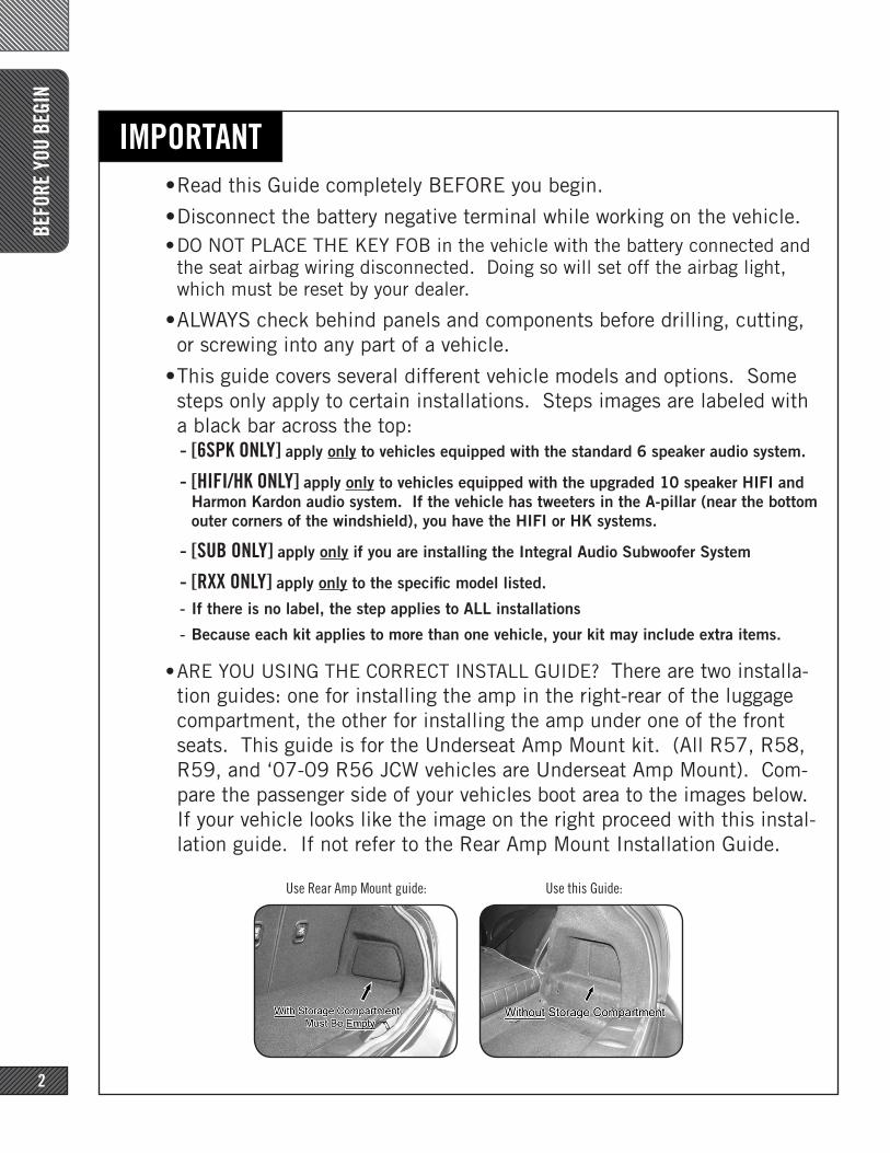
• ARE YOU USING THE CORRECT INSTALL GUIDE? There are two installa-tion guides: one for installing the amp in the right-rear of the luggage compartment, the other for installing the amp under one of the front seats. This guide is for the Underseat Amp Mount kit. (All R57, R58, R59, and ‘07-09 R56 JCW vehicles are Underseat Amp Mount). Com-pare the passenger side of your vehicles boot area to the images below. If your vehicle looks like the image on the right proceed with this instal-lation guide. If not refer to the Rear Amp Mount Installation Guide.
IMPORTANT
Use Rear Amp Mount guide: Use this Guide:
WHA
T’S
IN T
HE B
OX
3
SOUN
DSTA
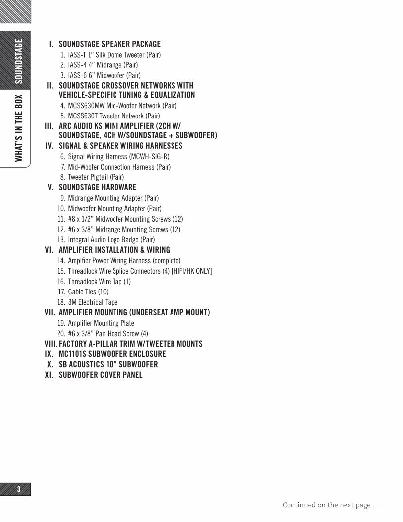
GE I. SOUNDSTAGE SPEAKER PACKAGE1. IASS-T 1” Silk Dome Tweeter (Pair)2. IASS-4 4” Midrange (Pair)3. IASS-6 6” Midwoofer (Pair)
II. SOUNDSTAGE CROSSOVER NETWORKS WITH VEHICLE-SPECIFIC TUNING & EQUALIZATION4. MCSS630MW Mid-Woofer Network (Pair)5. MCSS630T Tweeter Network (Pair)
III. ARC AUDIO KS MINI AMPLIFIER (2CH W/SOUNDSTAGE, 4CH W/SOUNDSTAGE + SUBWOOFER)
IV. SIGNAL & SPEAKER WIRING HARNESSES6. Signal Wiring Harness (MCWH-SIG-R)7. Mid-Woofer Connection Harness (Pair)8. Tweeter Pigtail (Pair)
V. SOUNDSTAGE HARDWARE9. Midrange Mounting Adapter (Pair)
10. Midwoofer Mounting Adapter (Pair)11. #8 x 1/2” Midwoofer Mounting Screws (12)12. #6 x 3/8” Midrange Mounting Screws (12)13. Integral Audio Logo Badge (Pair)
VI. AMPLIFIER INSTALLATION & WIRING14. Amplfier Power Wiring Harness (complete) 15. Threadlock Wire Splice Connectors (4) [HIFI/HK ONLY]16. Threadlock Wire Tap (1)17. Cable Ties (10)18. 3M Electrical Tape
VII. AMPLIFIER MOUNTING (UNDERSEAT AMP MOUNT)19. Amplifier Mounting Plate20. #6 x 3/8” Pan Head Screw (4)
VIII. FACTORY A-PILLAR TRIM W/TWEETER MOUNTSIX. MC1101S SUBWOOFER ENCLOSUREX. SB ACOUSTICS 10” SUBWOOFER
XI. SUBWOOFER COVER PANEL
Continued on the next page . . .
WHA
T’S
IN T
HE B
OX
4
SUBW
OOFE
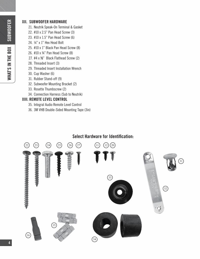
R XII. SUBWOOFER HARDWARE21. Neutrik Speak-On Terminal & Gasket22. #10 x 2.5” Pan Head Screw (3) 23. #10 x 1.5” Pan Head Screw (6)24. ¼” x 1” Hex Head Bolt25. #10 x 1” Black Pan Head Screw (8)26. #10 x ¾” Pan Head Screw (8)27. #4 x 1/2” Black Flathead Screw (2)28. Threaded Insert (3) 29. Threaded Insert Installation Wrench30. Cup Washer (6)31. Rubber Stand-off (9)32. Subwoofer Mounting Bracket (2)33. Rosette Thumbscrew (2)34. Connection Harness (Sub to Neutrik)
XIII. REMOTE LEVEL CONTROL35. Integral Audio Remote Level Control36. 3M VHB Double-Sided Mounting Tape (3in)
SeSelect Hardware for Identification:
2422 26
31
2012112725
33
1634
32
15
23

TOOL
S YO
U W
ILL
NEED
5Images Not to Scale
I. PLASTIC PANEL REMOVAL TOOLS II. TORX BITS:
1. T252. T303. T404. T50
III. DRILLIV. DRILL BIT:
5. 7/16” [MUST be correct size!]V. WRENCHES OR SOCKETS:
6. 7/16”7. 8mm8. 10mm9. 10mm Deep [optional}
10. 19mmVI. ELECTRICIAN’S WIRE FISHVII. SCISSORSVIII. UTILITY KNIFE IX. PLIERSX. DIGITAL MULTIMETER
XI. TEST TONE CD (availble for download atwww.integralaudio.com/other_files/test_cd/)
XII. CENTER PUNCH [SUB ONLY] XIII. WIRE STRIPPER [HIFI/HK ONLY]XIV. PICK & HOOK SET [OPTIONAL]XV. MAGNETIC PARTS TRAY [OPTIONAL]
A. PR
EP V
EHIC
LE
6
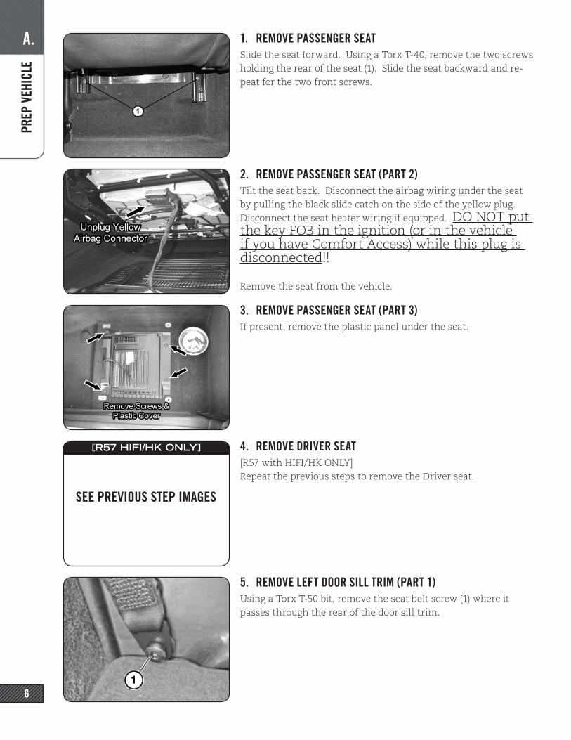
1. REMOVE PASSENGER SEATSlide the seat forward. Using a Torx T-40, remove the two screws holding the rear of the seat (1). Slide the seat backward and re-peat for the two front screws.
2. REMOVE PASSENGER SEAT (PART 2)Tilt the seat back. Disconnect the airbag wiring under the seat by pulling the black slide catch on the side of the yellow plug. Disconnect the seat heater wiring if equipped. DO NOT put the key FOB in the ignition (or in the vehicle if you have Comfort Access) while this plug is disconnected!!
Remove the seat from the vehicle.
3. REMOVE PASSENGER SEAT (PART 3)If present, remove the plastic panel under the seat.
4. REMOVE DRIVER SEAT[R57 with HIFI/HK ONLY]Repeat the previous steps to remove the Driver seat.
5. REMOVE LEFT DOOR SILL TRIM (PART 1)Using a Torx T-50 bit, remove the seat belt screw (1) where it passes through the rear of the door sill trim.
\
SEE PREVIOUS STEP IMAGES
[R57 HIFI/HK ONLY]
A. PR
EP V
EHIC
LE
7
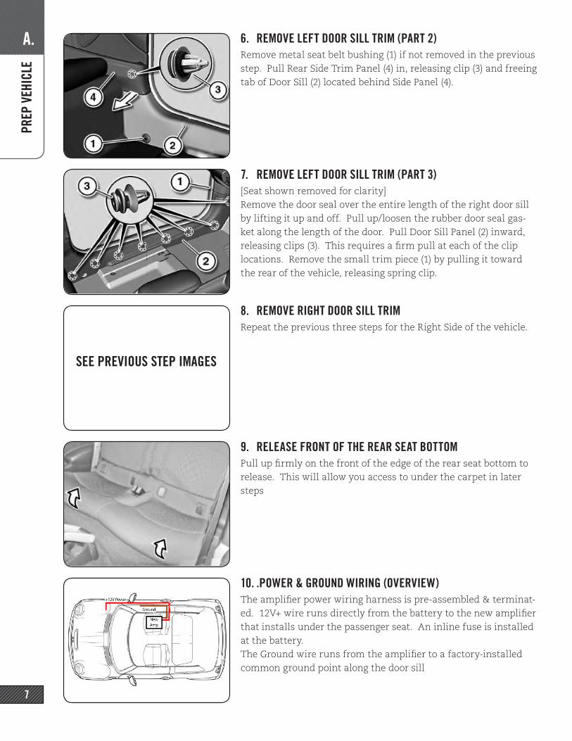
6. REMOVE LEFT DOOR SILL TRIM (PART 2)Remove metal seat belt bushing (1) if not removed in the previous step. Pull Rear Side Trim Panel (4) in, releasing clip (3) and freeing tab of Door Sill (2) located behind Side Panel (4).
7. REMOVE LEFT DOOR SILL TRIM (PART 3)[Seat shown removed for clarity]Remove the door seal over the entire length of the right door sill by lifting it up and off. Pull up/loosen the rubber door seal gas-ket along the length of the door. Pull Door Sill Panel (2) inward, releasing clips (3). This requires a firm pull at each of the clip locations. Remove the small trim piece (1) by pulling it toward the rear of the vehicle, releasing spring clip.
8. REMOVE RIGHT DOOR SILL TRIMRepeat the previous three steps for the Right Side of the vehicle.
9. RELEASE FRONT OF THE REAR SEAT BOTTOMPull up firmly on the front of the edge of the rear seat bottom to release. This will allow you access to under the carpet in later steps
10. .POWER & GROUND WIRING (OVERVIEW)The amplifier power wiring harness is pre-assembled & terminat-ed. 12V+ wire runs directly from the battery to the new amplifier that installs under the passenger seat. An inline fuse is installed at the battery. The Ground wire runs from the amplifier to a factory-installed common ground point along the door sill
SEE PREVIOUS STEP IMAGES
B. PO
WER
& G
ROUN
D W
IRIN
G
8
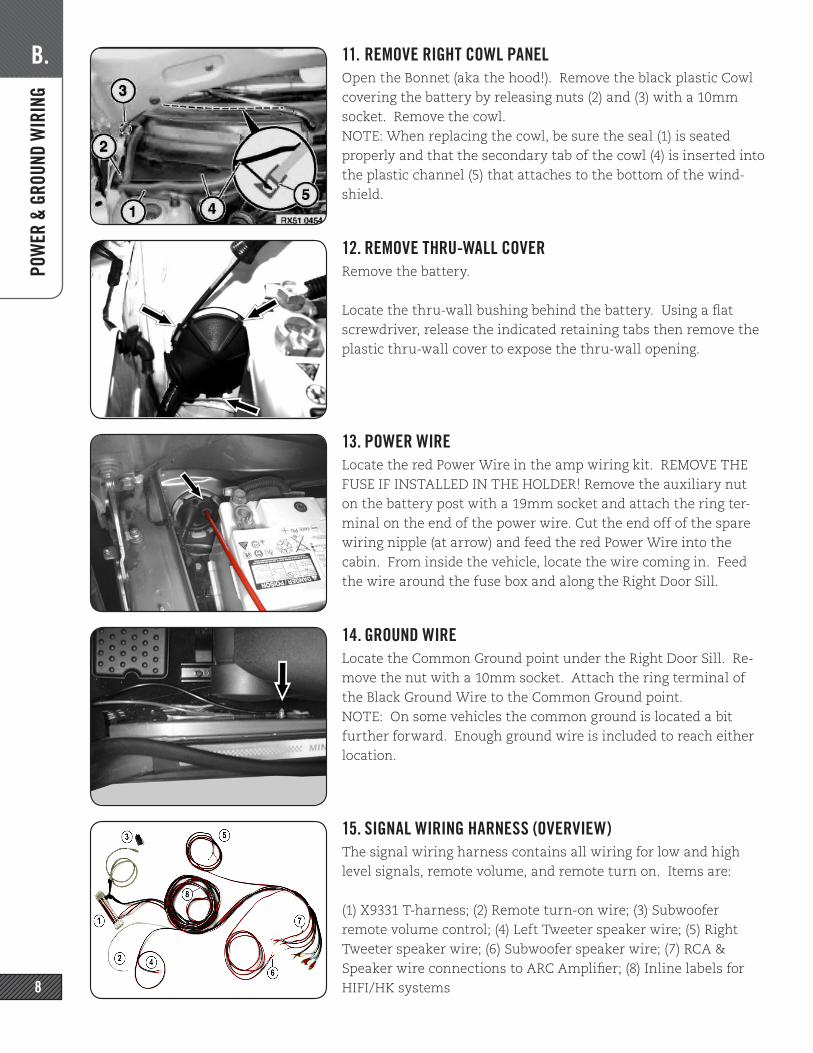
11. REMOVE RIGHT COWL PANELOpen the Bonnet (aka the hood!). Remove the black plastic Cowl covering the battery by releasing nuts (2) and (3) with a 10mm socket. Remove the cowl.NOTE: When replacing the cowl, be sure the seal (1) is seated properly and that the secondary tab of the cowl (4) is inserted into the plastic channel (5) that attaches to the bottom of the wind-shield.
12. REMOVE THRU-WALL COVERRemove the battery.
Locate the thru-wall bushing behind the battery. Using a flat screwdriver, release the indicated retaining tabs then remove the plastic thru-wall cover to expose the thru-wall opening.
13. POWER WIRELocate the red Power Wire in the amp wiring kit. REMOVE THE FUSE IF INSTALLED IN THE HOLDER! Remove the auxiliary nut on the battery post with a 19mm socket and attach the ring ter-minal on the end of the power wire. Cut the end off of the spare wiring nipple (at arrow) and feed the red Power Wire into the cabin. From inside the vehicle, locate the wire coming in. Feed the wire around the fuse box and along the Right Door Sill.
14. GROUND WIRELocate the Common Ground point under the Right Door Sill. Re-move the nut with a 10mm socket. Attach the ring terminal of the Black Ground Wire to the Common Ground point.NOTE: On some vehicles the common ground is located a bit further forward. Enough ground wire is included to reach either location.
15. SIGNAL WIRING HARNESS (OVERVIEW)The signal wiring harness contains all wiring for low and high level signals, remote volume, and remote turn on. Items are:
(1) X9331 T-harness; (2) Remote turn-on wire; (3) Subwoofer remote volume control; (4) Left Tweeter speaker wire; (5) Right Tweeter speaker wire; (6) Subwoofer speaker wire; (7) RCA & Speaker wire connections to ARC Amplifier; (8) Inline labels for HIFI/HK systems
C. SI
GNAL
WIR
ING
9
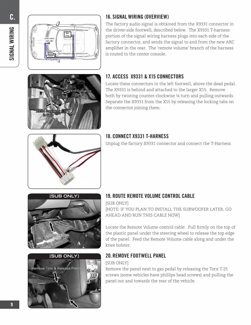
16. SIGNAL WIRING (OVERVIEW)The factory audio signal is obtained from the X9331 connector in the driver-side footwell, described below. The X9331 T-harness portion of the signal wiring harness plugs into each side of the factory connector, and sends the signal to and from the new ARC amplifier in the rear. The ‘remote volume’ branch of the harness is routed to the center console.
17. ACCESS X9331 & X15 CONNECTORSLocate these connectors in the left footwell, above the dead pedal. The X9331 is behind and attached to the larger X15. Remove both by twisting counter-clockwise ¼ turn and pulling outwards. Separate the X9331 from the X15 by releasing the locking tabs on the connector joining them.
18. CONNECT X9331 T-HARNESSUnplug the factory X9331 connector and connect the T-Harness
19. ROUTE REMOTE VOLUME CONTROL CABLE[SUB ONLY][NOTE: IF YOU PLAN TO INSTALL THE SUBWOOFER LATER, GO AHEAD AND RUN THIS CABLE NOW]
Locate the Remote Volume control cable. Pull firmly on the top of the plastic panel under the steering wheel to release the top edge of the panel. Feed the Remote Volume cable along and under the knee bolster.
20. REMOVE FOOTWELL PANEL[SUB ONLY]Remove the panel next to gas pedal by releasing the Torx T-25 screws (some vehicles have phillips head screws) and pulling the panel out and towards the rear of the vehicle.
[SUB ONLY]
[SUB ONLY]

C. SI
GNAL
WIR
ING
10
21. ROUTE REMOTE LEVEL CONTROL[SUB ONLY]Run the Remote Level Control cable above the metal shown and then thru the gap under the bottom edge of the center console.
. REMOTE LEVEL CONTROL[SUB ONLY]Assemble the Remote Level Control by inserting shaft-first into the housing and fastening with the washers and nut. Slide the knob over the shaft. Attach the 3M VHB double-sided adhesive (this is the green 3in length) to the top of the Remote Level Control housing. Trim extra length from the VHB, if necessary. Wipe both surfaces with one of the Alcohol Prep Pads before applying.
22. MOUNT REMOTE LEVEL CONTROL[SUB ONLY]Connect the cable to the Remote Level Control. Mount the Re-mote Level Control below the toggle switches. Wipe the surface with the Alcohol Prep Pad before applying.Do a dry-run to check the placement and be sure you know exact-ly where you’d like the control. You will find that you can place it more toward the front of the recess for easier access, or toward the rear for a more hidden look.
23. CUT & RELEASE MID/MIDWOOFER SPEAKER WIRES[HIFI/HK ONLY] [HIFI/HK ONLY] [HIFI/HK ONLY] [HIFI/HK ONLY]For HIFI/HK equipped vehicles ONLY! Cut the Mid/Woofer Speaker wires at the X9331 T-Harness. Remove the wires from the rest of the harness bundle UP TO WITHIN 8 FEET OF THE RCAS at the other end of the harness.These wires will be used later to connect to the factory wiring downstream of the HIFI/HK amplifier.
24. REMOTE TURN-ON WIREIdentify the solid black wire coming out of pin 1 of the X15 con-nector (from previous step). Locate the 18AWG White Remote turn-on Lead wire in the signal harness. Unscrew both ends of the Threadlock wiretap (the tap has a hole in only one end) Slip the “U”-shaped bottom around the signal wire to be tapped. Care-fully thread the body of the tap onto this and tighten firmly. Be sure not to cross-thread the tap.
[SUB ONLY]
[SUB ONLY]
[SUB ONLY]
[HIFI/HK ONLY]
C. SI
GNAL
WIR
ING
11
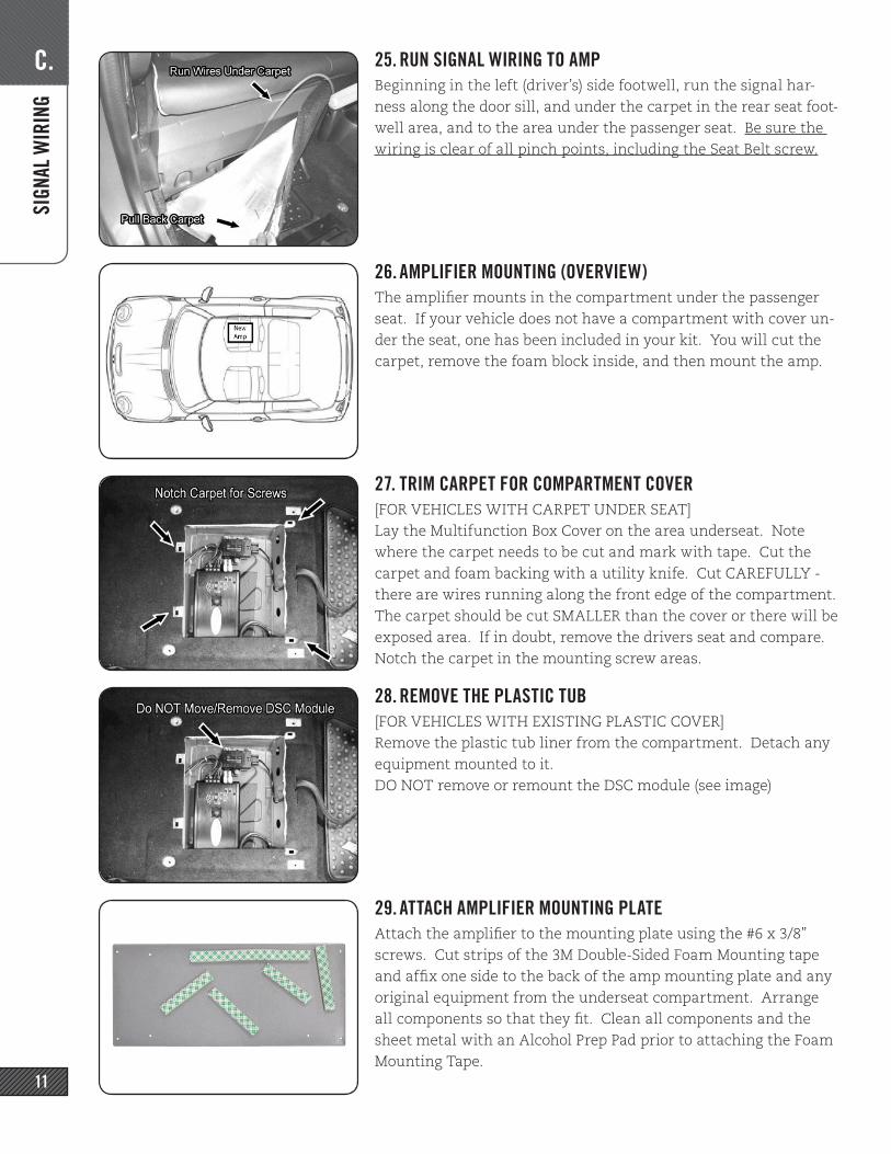
25. RUN SIGNAL WIRING TO AMPBeginning in the left (driver’s) side footwell, run the signal har-ness along the door sill, and under the carpet in the rear seat foot-well area, and to the area under the passenger seat. Be sure the wiring is clear of all pinch points, including the Seat Belt screw.
26. AMPLIFIER MOUNTING (OVERVIEW)The amplifier mounts in the compartment under the passenger seat. If your vehicle does not have a compartment with cover un-der the seat, one has been included in your kit. You will cut the carpet, remove the foam block inside, and then mount the amp.
27. TRIM CARPET FOR COMPARTMENT COVER[FOR VEHICLES WITH CARPET UNDER SEAT]Lay the Multifunction Box Cover on the area underseat. Note where the carpet needs to be cut and mark with tape. Cut the carpet and foam backing with a utility knife. Cut CAREFULLY - there are wires running along the front edge of the compartment. The carpet should be cut SMALLER than the cover or there will be exposed area. If in doubt, remove the drivers seat and compare. Notch the carpet in the mounting screw areas.
28. REMOVE THE PLASTIC TUB[FOR VEHICLES WITH EXISTING PLASTIC COVER]Remove the plastic tub liner from the compartment. Detach any equipment mounted to it. DO NOT remove or remount the DSC module (see image)
29. ATTACH AMPLIFIER MOUNTING PLATEAttach the amplifier to the mounting plate using the #6 x 3/8” screws. Cut strips of the 3M Double-Sided Foam Mounting tape and affix one side to the back of the amp mounting plate and any original equipment from the underseat compartment. Arrange all components so that they fit. Clean all components and the sheet metal with an Alcohol Prep Pad prior to attaching the Foam Mounting Tape.
D. SO
UNDS
TAGE
12
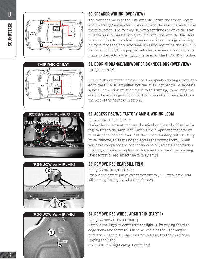
30. SPEAKER WIRING (OVERVIEW)The front channels of the ARC amplifier drive the front tweeter and midrange/midwoofer in parallel, and the rear channels drive the subwoofer. The factory HU/Amp continues to drive the rear fill speakers. Separate wires are run from the amp the tweeters in all vehicles. In Standard 6 speaker vehicles, the signal wiring harness feeds the door midrange and midwoofer via the X9331 T-harness. In HiFi/HK equipped vehicles, a separate connection is made to the factory wiring downstream of the HiFi/HK amplifier.
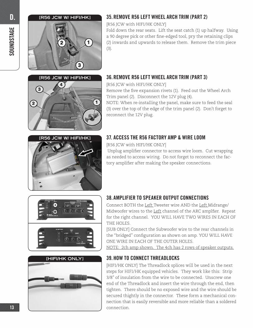
31. DOOR MIDRANGE/MIDWOOFER CONNECTIONS (OVERVIEW)[HIFI/HK ONLY]
In HIFI/HK equipped vehicles, the door speaker wiring is connect-ed to the HIFI/HK amplifier, not the X9331 connector. A separate spliced connection must be made to this wiring, connecting the end of the midrange/midwoofer that was cut and removed from the rest of the harness in step 23.
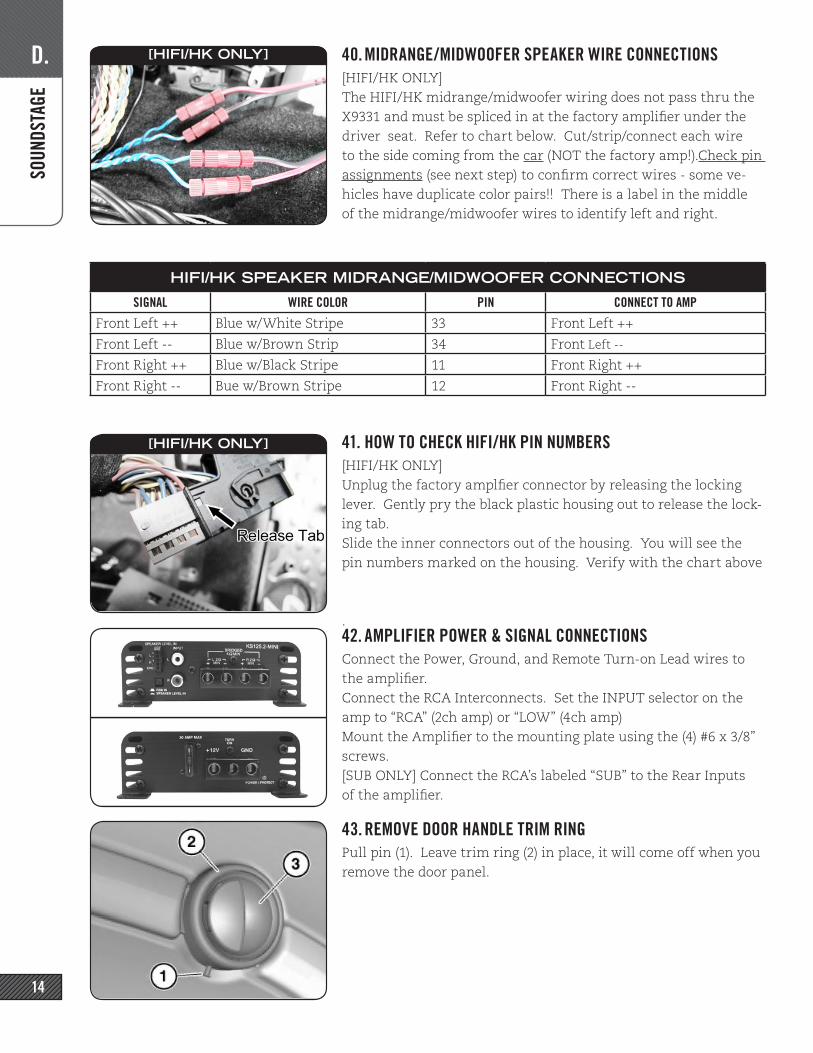
32. ACCESS R57/8/9 FACTORY AMP & WIRING LOOM[R57/8/9 w/ HIFI/HK ONLY]Under the driver seat, remove the wire bundle and rubber bush-ing leading to the amplifier. Unplug the amplifier connector by releasing the locking lever. Slit the rubber bushing with a utility knife, remove, and set aside to access the wiring loom. When you have completed the connections below, reinstall the rubber bushing and secure in place with a wire tie around the bushing. Don’t forget to reconnect the factory amp!
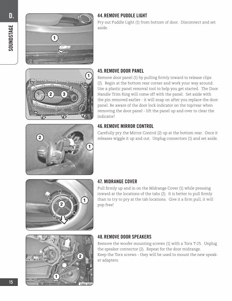
33. REMOVE R56 REAR SILL TRIM[R56 JCW w/ HIFI/HK ONLY]Pry out the center pin of expansion rivets (1). Remove the rear sill trim by lifting up, releasing clips (2).
34. REMOVE R56 WHEEL ARCH TRIM (PART 1)[R56 JCW with HIFI/HK ONLY]Remove the luggage compartment light (1) by prying the rear edge down and forward. On some vehicles the light may be reversed - if the rear edge does not release, try the front edge. Unplug the light. CAUTION: the light can get quite hot!
[HIFI/HK ONLY]
[R57/8/9 w/ HIFI/HK ONLY]
[R56 JCW w/ HIFI/HK]
[R56 JCW W/ HIFI/HK]
D. SO
UNDS
TAGE
13
35. REMOVE R56 LEFT WHEEL ARCH TRIM (PART 2)[R56 JCW with HIFI/HK ONLY]Fold down the rear seats. Lift the seat catch (1) up halfway. Using a 90 degree pick or other fine-edged tool, pry the retaining clips (2) inwards and upwards to release them. Remove the trim piece (3).
36. REMOVE R56 LEFT WHEEL ARCH TRIM (PART 3)[R56 JCW with HIFI/HK ONLY]Remove the five expansion rivets (1). Feed out the Wheel Arch Trim panel (2). Disconnect the 12V plug (4). NOTE: When re-installing the panel, make sure to feed the seal (3) over the top of the edge of the trim panel (2). Don’t forget to reconnect the 12V plug.
37. ACCESS THE R56 FACTORY AMP & WIRE LOOM[R56 JCW with HIFI/HK ONLY] Unplug amplifier connector to access wire loom. Cut wrapping as needed to access wiring. Do not forget to reconnect the fac-tory amplifier after making the speaker connections.
38. AMPLIFIER TO SPEAKER OUTPUT CONNECTIONSConnect BOTH the Left Tweeter wire AND the Left Midrange/Midwoofer wires to the Left channel of the ARC amplfier. Repeat for the right channel. YOU WILL HAVE TWO WIRES IN EACH OF THE HOLES.[SUB ONLY] Connect the Subwoofer wire to the rear channels in the “bridged” configuration as shown on amp. YOU WILL HAVE ONE WIRE IN EACH OF THE OUTER HOLES.NOTE: 2ch amp shown. The 4ch has 2 rows of speaker outputs. 39. HOW TO CONNECT THREADLOCKS[HIFI/HK ONLY] The Threadlock splices will be used in the next steps for HIFI/HK equipped vehicles. They work like this: Strip 3/8” of insulation from the wire to be connected. Unscrew one end of the Threadlock and insert the wire through the end, then tighten. There should be no exposed wire and the wire should be secured thightly in the connector. These form a mechanical con-nection that is easily reversible and more reliable than a soldered connection.
[R56 JCW W/ HIFI/HK]
[R56 JCW W/ HIFI/HK]
[R56 JCW W/ HIFI/HK]
[HIFI/HK ONLY]
D. SO
UNDS
TAGE
14
40. MIDRANGE/MIDWOOFER SPEAKER WIRE CONNECTIONS[HIFI/HK ONLY]The HIFI/HK midrange/midwoofer wiring does not pass thru the X9331 and must be spliced in at the factory amplifier under the driver seat. Refer to chart below. Cut/strip/connect each wire to the side coming from the car (NOT the factory amp!).Check pin assignments (see next step) to confirm correct wires - some ve-hicles have duplicate color pairs!! There is a label in the middle of the midrange/midwoofer wires to identify left and right.
41. HOW TO CHECK HIFI/HK PIN NUMBERS[HIFI/HK ONLY]Unplug the factory amplfier connector by releasing the locking lever. Gently pry the black plastic housing out to release the lock-ing tab. Slide the inner connectors out of the housing. You will see the pin numbers marked on the housing. Verify with the chart above
.42. AMPLIFIER POWER & SIGNAL CONNECTIONSConnect the Power, Ground, and Remote Turn-on Lead wires to the amplifier. Connect the RCA Interconnects. Set the INPUT selector on the amp to “RCA” (2ch amp) or “LOW” (4ch amp) Mount the Amplifier to the mounting plate using the (4) #6 x 3/8” screws. [SUB ONLY] Connect the RCA’s labeled “SUB” to the Rear Inputs of the amplifier.
43. REMOVE DOOR HANDLE TRIM RINGPull pin (1). Leave trim ring (2) in place, it will come off when you remove the door panel.
[HIFI/HK ONLY]
HIFI/HK SPEAKER MIDRANGE/MIDWOOFER CONNECTIONS
SIGNAL WIRE COLOR PIN CONNECT TO AMP
Front Left ++ Blue w/White Stripe 33 Front Left ++
Front Left -- Blue w/Brown Strip 34 Front Left --
Front Right ++ Blue w/Black Stripe 11 Front Right ++
Front Right -- Bue w/Brown Stripe 12 Front Right --
[HIFI/HK ONLY]
D. SO
UNDS
TAGE
15
44. REMOVE PUDDLE LIGHTPry out Puddle Light (1) from bottom of door. Disconnect and set aside.
45. REMOVE DOOR PANELRemove door panel (1) by pulling firmly inward to release clips (2). Begin at the bottom rear corner and work your way around. Use a plastic panel removal tool to help you get started. The Door Handle Trim Ring will come off with the panel. Set aside with the pin removed earlier - it will snap on after you replace the door panel. Be aware of the door lock indicator on the top/rear when removing the door panel - lift the panel up and over to clear the indicator!
46. REMOVE MIRROR CONTROLCarefully pry the Mirror Control (2) up at the bottom rear. Once it releases wiggle it up and out. Unplug connectors (1) and set aside.
47. MIDRANGE COVERPull firmly up and in on the Midrange Cover (1) while pressing inward at the locations of the tabs (2). It is better to pull firmly than to try to pry at the tab locations. Give it a firm pull, it will pop free!
48. REMOVE DOOR SPEAKERSRemove the woofer mounting screws (1) with a Torx T-25. Unplug the speaker connector (2). Repeat for the door midrange.Keep the Torx screws - they will be used to mount the new speak-er adapters.
D. SO
UNDS
TAGA
E
16
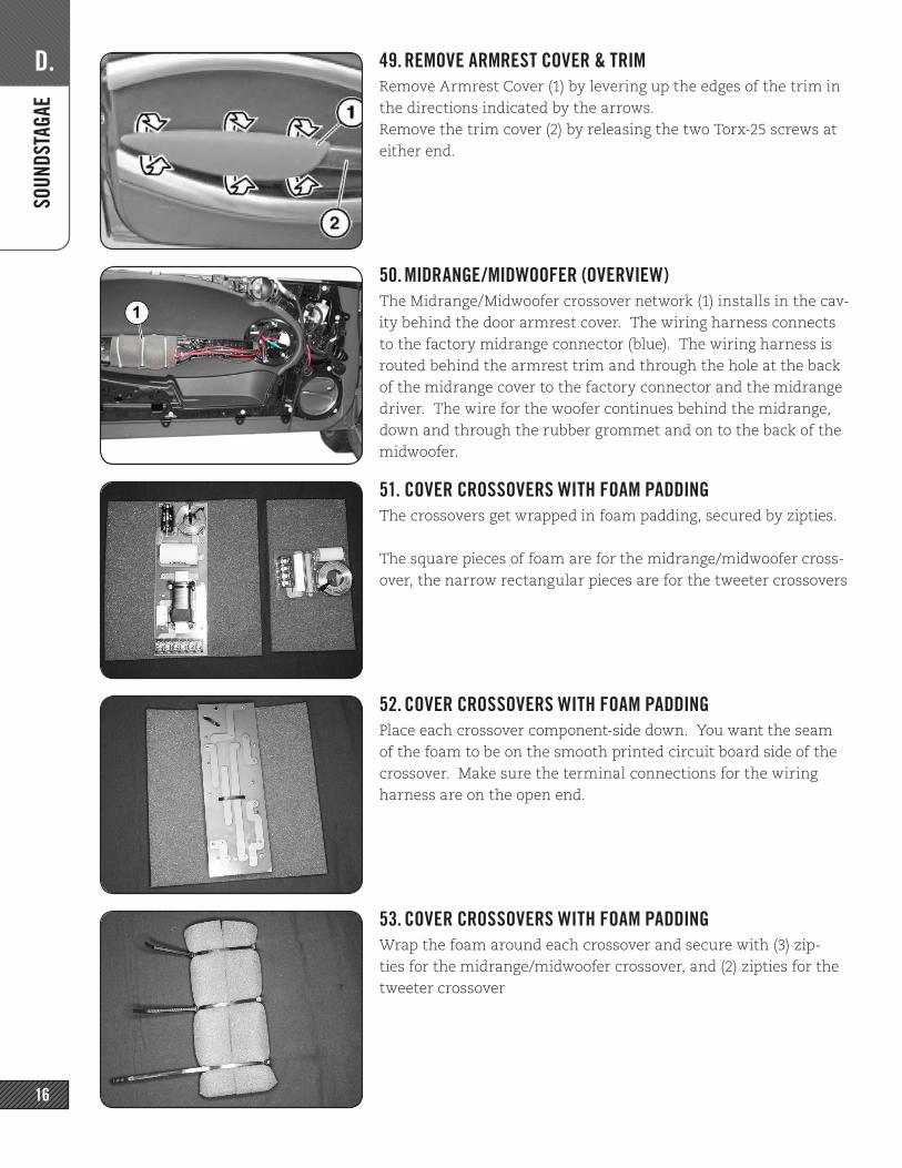
49. REMOVE ARMREST COVER & TRIMRemove Armrest Cover (1) by levering up the edges of the trim in the directions indicated by the arrows. Remove the trim cover (2) by releasing the two Torx-25 screws at either end.
50. MIDRANGE/MIDWOOFER (OVERVIEW)The Midrange/Midwoofer crossover network (1) installs in the cav-ity behind the door armrest cover. The wiring harness connects to the factory midrange connector (blue). The wiring harness is routed behind the armrest trim and through the hole at the back of the midrange cover to the factory connector and the midrange driver. The wire for the woofer continues behind the midrange, down and through the rubber grommet and on to the back of the midwoofer.
51. COVER CROSSOVERS WITH FOAM PADDINGThe crossovers get wrapped in foam padding, secured by zipties.
The square pieces of foam are for the midrange/midwoofer cross-over, the narrow rectangular pieces are for the tweeter crossovers
52. COVER CROSSOVERS WITH FOAM PADDINGPlace each crossover component-side down. You want the seam of the foam to be on the smooth printed circuit board side of the crossover. Make sure the terminal connections for the wiring harness are on the open end.
53. COVER CROSSOVERS WITH FOAM PADDINGWrap the foam around each crossover and secure with (3) zip-ties for the midrange/midwoofer crossover, and (2) zipties for the tweeter crossover
D. SO
UNDS
TAGE
17
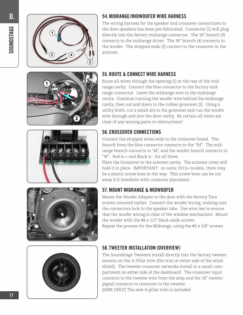
54. MIDRANGE/MIDWOOFER WIRE HARNESSThe wiring harness for the speaker and crossover connections to the door speakers has been pre-fabricated. Connector (1) will plug directly into the factory midrange connector. The 18” branch (3) connects to the midrange driver. The 36” branch (4) connects to the woofer. The stripped ends (2) connect to the crossover in the armrest.
55. ROUTE & CONNECT WIRE HARNESSRoute all wires through the opening (1) at the rear of the mid-range cavity. Connect the blue connector to the factory mid-range connector. Leave the midrange wire in the midrange cavity. Continue running the woofer wire behind the midrange cavity, then out and down to the rubber grommet (2). Using a utility knife, cut a small slit in the grommet and run the woofer wire through and into the door cavity. Be certain all wires are clear of any moving parts or obstructions!
56. CROSSOVER CONNECTIONSConnect the stripped wires ends to the crossover board. The branch from the blue connector connects to the “IN”. The mid-range branch connects to “M”, and the woofer branch connects to “W”. Red is + and Black is - for all three. Place the Crossover in the armrest cavity. The armrest cover will hold it in place. IMPORTANT: on some 2013+ models, there may be a plastic screw boss in the way. This screw boss can be cut away if it interferes with crossover placement.
57. MOUNT MIDRANGE & MIDWOOFERMount the Woofer Adapter to the door with the factory Torx screws removed earlier. Connect the woofer wiring, making sure the connectors lock to the speaker tabs. Use wire ties to ensure that the woofer wiring is clear of the window mechanism! Mount the woofer with the #8 x 1/2” black oxide screws.Repeat the process for the Midrange, using the #6 x 3/8” screws.
58. TWEETER INSTALLATION (OVERVIEW)The Soundstage Tweeters install directly into the factory tweeter mounts on the A-Pillar trim (the trim at either side of the wind-shield). The tweeter crossover networks install in a small com-partment on either side of the dashboard. The crossover input connects to the tweeter wire from the amp and the 18” tweeter pigtail connects to crossover to the tweeter.[6SPK ONLY] The new A-pillar trim is included
E. SU
BWOO
FER
18
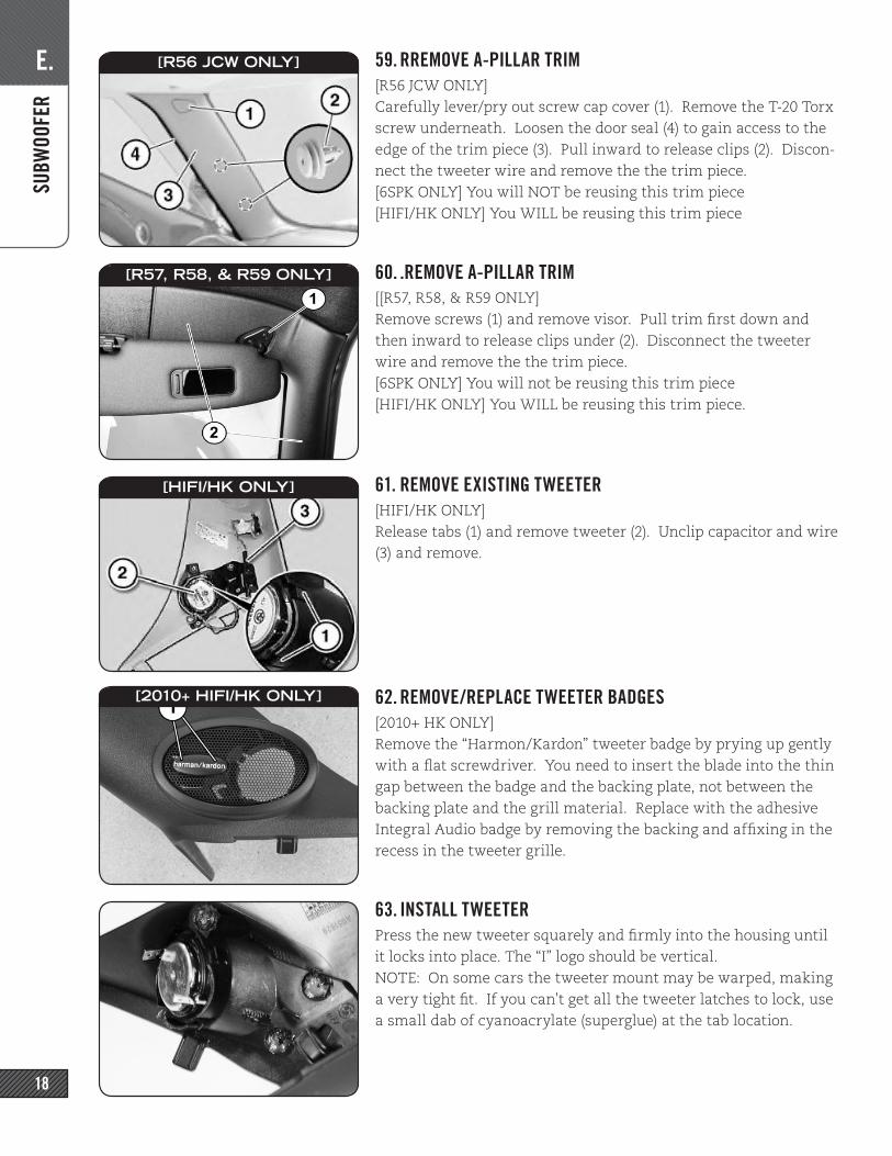
59. RREMOVE A-PILLAR TRIM[R56 JCW ONLY]Carefully lever/pry out screw cap cover (1). Remove the T-20 Torx screw underneath. Loosen the door seal (4) to gain access to the edge of the trim piece (3). Pull inward to release clips (2). Discon-nect the tweeter wire and remove the the trim piece.[6SPK ONLY] You will NOT be reusing this trim piece[HIFI/HK ONLY] You WILL be reusing this trim piece
60. .REMOVE A-PILLAR TRIM[[R57, R58, & R59 ONLY]Remove screws (1) and remove visor. Pull trim first down and then inward to release clips under (2). Disconnect the tweeter wire and remove the the trim piece.[6SPK ONLY] You will not be reusing this trim piece[HIFI/HK ONLY] You WILL be reusing this trim piece.
61. REMOVE EXISTING TWEETER[HIFI/HK ONLY]Release tabs (1) and remove tweeter (2). Unclip capacitor and wire (3) and remove.
62. REMOVE/REPLACE TWEETER BADGES[2010+ HK ONLY]Remove the “Harmon/Kardon” tweeter badge by prying up gently with a flat screwdriver. You need to insert the blade into the thin gap between the badge and the backing plate, not between the backing plate and the grill material. Replace with the adhesive Integral Audio badge by removing the backing and affixing in the recess in the tweeter grille.
63. INSTALL TWEETERPress the new tweeter squarely and firmly into the housing until it locks into place. The “I” logo should be vertical.NOTE: On some cars the tweeter mount may be warped, making a very tight fit. If you can’t get all the tweeter latches to lock, use a small dab of cyanoacrylate (superglue) at the tab location.
[R56 JCW ONLY]
[R57, R58, & R59 ONLY]
[HIFI/HK ONLY]
[2010+ HIFI/HK ONLY]
E. SU
BWOO
FER
19
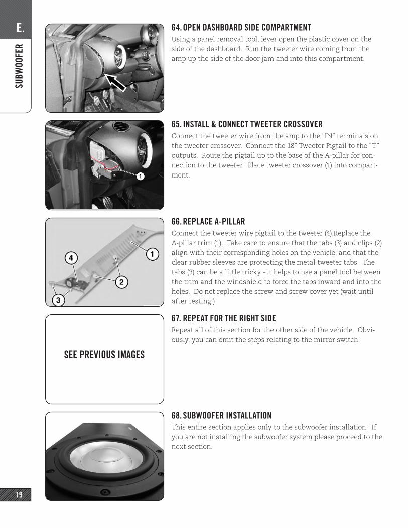
64. OPEN DASHBOARD SIDE COMPARTMENTUsing a panel removal tool, lever open the plastic cover on the side of the dashboard. Run the tweeter wire coming from the amp up the side of the door jam and into this compartment.
65. INSTALL & CONNECT TWEETER CROSSOVERConnect the tweeter wire from the amp to the “IN” terminals on the tweeter crossover. Connect the 18” Tweeter Pigtail to the “T” outputs. Route the pigtail up to the base of the A-pillar for con-nection to the tweeter. Place tweeter crossover (1) into compart-ment.
66. REPLACE A-PILLARConnect the tweeter wire pigtail to the tweeter (4).Replace the A-pillar trim (1). Take care to ensure that the tabs (3) and clips (2) align with their corresponding holes on the vehicle, and that the clear rubber sleeves are protecting the metal tweeter tabs. The tabs (3) can be a little tricky - it helps to use a panel tool between the trim and the windshield to force the tabs inward and into the holes. Do not replace the screw and screw cover yet (wait until after testing!)
67. REPEAT FOR THE RIGHT SIDERepeat all of this section for the other side of the vehicle. Obvi-ously, you can omit the steps relating to the mirror switch!
68. SUBWOOFER INSTALLATIONThis entire section applies only to the subwoofer installation. If you are not installing the subwoofer system please proceed to the next section.
SEE PREVIOUS IMAGES
E. SU
BWOO
FER
20
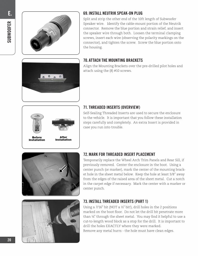
69. INSTALL NEUTRIK SPEAK-ON PLUGSplit and strip the other end of the 10ft length of Subwoofer Speaker wire. Identify the cable-mount portion of the Neutrik connector. Remove the blue portion and strain relief, and insert the speaker wire through both. Loosen the terminal clamping screws, insert each wire (observing the polarity markings on the connector), and tighten the screw. Screw the blue portion onto the housing.
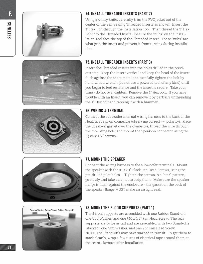
70. ATTACH THE MOUNTING BRACKETSAlign the Mounting Brackets over the pre-drilled pilot holes and attach using the (8) #10 screws.
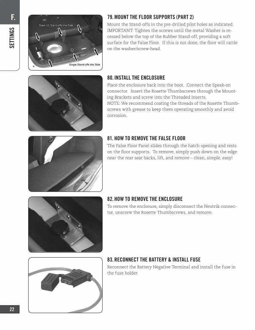
71. THREADED INSERTS (OVERVIEW)Self-Sealing Threaded Inserts are used to secure the enclosure to the vehicle. It is important that you follow these installation steps carefully and completely. An extra Insert is provided in case you run into trouble.
72. MARK FOR THREADED INSERT PLACEMENTTemporarily replace the Wheel Arch Trim Panels and Rear Sill, if previously removed. Center the enclosure in the boot. Using a center punch (or marker), mark the center of the mounting brack-et hole in the sheet metal below. Keep the hole at least 3/8” away from the edges of the raised area of the sheet metal. Cut a notch in the carpet edge if necessary. Mark the center with a marker or center punch.
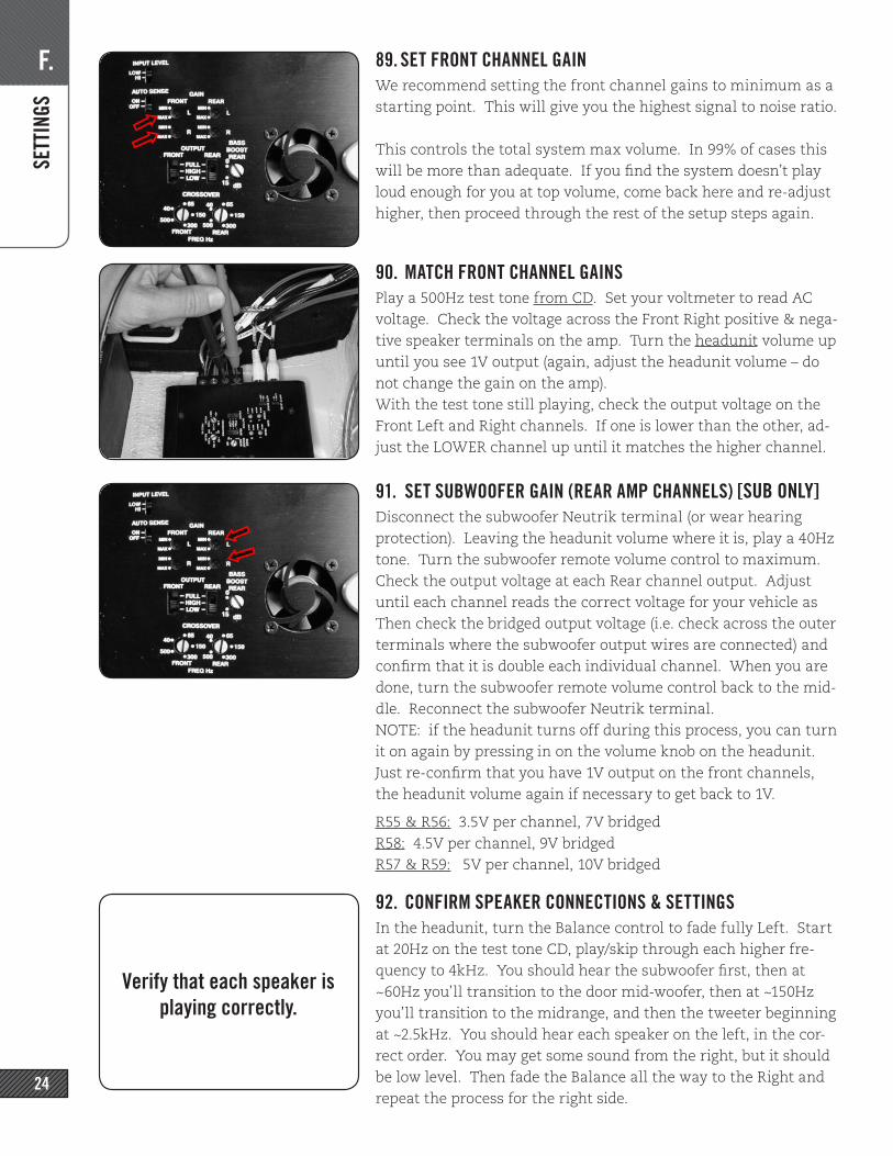
73. INSTALL THREADED INSERTS (PART 1)Using a 7/16” bit (NOT a ½” bit!), drill holes in the 2 positions marked on the boot floor. Do not let the drill bit penetrate more than ¼” through the sheet metal. You may find it helpful to use a cut-to-length wood block as a stop for the drill. It is important to drill the holes EXACTLY where they were marked.Remove any metal burrs - the hole must have clean edges.
F. SE
TTIN
GS
21
74. INSTALL THREADED INSERTS (PART 2)Using a utility knife, carefully trim the PVC jacket out of the center of the Self-Sealing Threaded Inserts as shown. Insert the 1” Hex Bolt through the Installation Tool. Then thread the 1” Hex Bolt into the Threaded Insert. Be sure the “nubs” on the Instal-lation Tool face the top of the Threaded Insert. These “nubs” are what grip the Insert and prevent it from turning during installa-tion.
75. INSTALL THREADED INSERTS (PART 3) Insert the Threaded Inserts into the holes drilled in the previ-ous step. Keep the Insert vertical and keep the head of the Insert flush against the sheet metal and carefully tighten the bolt by hand with a wrench (do not use a powered tool of any kind) until you begin to feel resistance and the insert is secure. Take your time - do not over-tighten. Remove the 1” Hex bolt. If you have trouble with an Insert, you can remove it by partially unthreading the 1” Hex bolt and tapping it with a hammer.
76. WIRING & TERMINALConnect the subwoofer internal wiring harness to the back of the Neutrik Speak-on connector (observing correct +/- polarity). Place the Speak-on gasket over the connector, thread the wire through the mounting hole, and mount the Speak-on connector using the (2) #4 x 1/2” screws..
77. MOUNT THE SPEAKERConnect the wiring harness to the subwoofer terminals. Mount the speaker with the #10 x 1” Black Pan Head Screws, using the pre-drilled pilot holes. Tighten the screws in a “star” pattern, go slowly and take care not to strip them. Make sure the speaker flange is flush against the enclosure – the gasket on the back of the speaker flange MUST make an airtight seal.
78. MOUNT THE FLOOR SUPPORTS (PART 1)The 3 front supports are assembled with one Rubber Stand-off, one Cup Washer, and one #10 x 1.5” Pan Head Screw. The rear supports are twice as tall and are assembled with two Stand-offs (stacked), one Cup Washer, and one 2.5” Pan Head Screw.NOTE: The Stand-offs may have warped in transit. To get them to stack cleanly, wrap a few turns of electrical tape around them at the seam. Remove after installation.
F. SE
TTIN
GS
22
79. MOUNT THE FLOOR SUPPORTS (PART 2)Mount the Stand-offs in the pre-drilled pilot holes as indicated.IMPORTANT: Tighten the screws until the metal Washer is re-cessed below the top of the Rubber Stand-off, providing a soft surface for the False Floor. If this is not done, the floor will rattle on the washer/screw-head.
80. INSTALL THE ENCLOSUREPlace the enclosure back into the boot. Connect the Speak-on connector. Insert the Rosette Thumbscrews through the Mount-ing Brackets and screw into the Threaded Inserts. NOTE: We recommend coating the threads of the Rosette Thumb-screws with grease to keep them operating smoothly and avoid corrosion.
81. HOW TO REMOVE THE FALSE FLOORThe False Floor Panel slides through the hatch opening and rests on the floor supports. To remove, simply push down on the edge near the rear seat backs, lift, and remove – clean, simple, easy!
82. HOW TO REMOVE THE ENCLOSURETo remove the enclosure, simply disconnect the Neutrik connec-tor, unscrew the Rosette Thumbscrews, and remove.
83. RECONNECT THE BATTERY & INSTALL FUSEReconnect the Battery Negative Terminal and install the fuse in the fuse holder.

F. SE
TTIN
GS
23
84. SETUP & TUNINGYOU MUST DO EACH STEP EXACTLY AS DESCRIBED. IF POSSI-BLE, HAVE SOMEONE ELSE READ THE INSTRUCTIONS TO YOU WHILE YOU PERFORM THE STEPS.
Do not reinstall any panels until you have confirmed that every-thing is operating properly.
85. REPLACE SEATS & RECONNECT AIRBAG WIRINGIf you removed them, replace the seats in vehicle and reconnect the yellow connector under the seat. You do not need to bolt the seat down yet. For under-seat amp installs, you can lean the seat back to gain access to the amp for settings.
Reconnect the vehicle battery.
86. INITIAL AMP SETTINGSInput Level: LOW. (on 2ch amp, look for a button on amp end)Auto Sense: OFF. (4ch amp only), BX2: OFF (2ch amp only)Gain (aka input sensitivity): minimum on all 4 channels. Output -> Front: HIGH (with Sub), FULL (w/o Subwoofer)Output -> Rear (i.e. subwoofer): LOW [SUB ONLY]Crossover -> Front: turn dial to minimum (full counter-clockwise). Note which part of the dial is pointing to 40Hz. Turn until that part points to 65Hz. Repeat for the Rear (subwoofer) Crossover.
87. SET GONG, BASS & TREBLE [BOOST AUDIO]If your speedo looks like the picture at right, you have BOOST Audio.
Select the music note button to bring up the tone controls. Scroll to the right. Set the gong volume to the lowest level Return to the tone controls menu and set BASS and TREBLE to flat. (THESE ARE CRITICAL)
88. SET GONG, BASS & TREBLE [NAV & MINI CONNECTED]If your speedo has a large screen at the center, you have Nav or MINI Connected.
From the music control section, select TONE -> VOLUME SET-TINGS -> GONG. Set the gong volume to the lowest level (Re-turn to the tone controls menu and set BASS and TREBLE to flat. (THESE ARE CRITICAL)
TEST!
F. SE
TTIN
GS
24
89. SET FRONT CHANNEL GAINWe recommend setting the front channel gains to minimum as a starting point. This will give you the highest signal to noise ratio.
This controls the total system max volume. In 99% of cases this will be more than adequate. If you find the system doesn’t play loud enough for you at top volume, come back here and re-adjust higher, then proceed through the rest of the setup steps again.
90. MATCH FRONT CHANNEL GAINSPlay a 500Hz test tone from CD. Set your voltmeter to read AC voltage. Check the voltage across the Front Right positive & nega-tive speaker terminals on the amp. Turn the headunit volume up until you see 1V output (again, adjust the headunit volume – do not change the gain on the amp).With the test tone still playing, check the output voltage on the Front Left and Right channels. If one is lower than the other, ad-just the LOWER channel up until it matches the higher channel.
91. SET SUBWOOFER GAIN (REAR AMP CHANNELS) [SUB ONLY]Disconnect the subwoofer Neutrik terminal (or wear hearing protection). Leaving the headunit volume where it is, play a 40Hz tone. Turn the subwoofer remote volume control to maximum. Check the output voltage at each Rear channel output. Adjust until each channel reads the correct voltage for your vehicle as Then check the bridged output voltage (i.e. check across the outer terminals where the subwoofer output wires are connected) and confirm that it is double each individual channel. When you are done, turn the subwoofer remote volume control back to the mid-dle. Reconnect the subwoofer Neutrik terminal.NOTE: if the headunit turns off during this process, you can turn it on again by pressing in on the volume knob on the headunit. Just re-confirm that you have 1V output on the front channels, the headunit volume again if necessary to get back to 1V.
R55 & R56: 3.5V per channel, 7V bridgedR58: 4.5V per channel, 9V bridgedR57 & R59: 5V per channel, 10V bridged
92. CONFIRM SPEAKER CONNECTIONS & SETTINGSIn the headunit, turn the Balance control to fade fully Left. Start at 20Hz on the test tone CD, play/skip through each higher fre-quency to 4kHz. You should hear the subwoofer first, then at ~60Hz you’ll transition to the door mid-woofer, then at ~150Hz you’ll transition to the midrange, and then the tweeter beginning at ~2.5kHz. You should hear each speaker on the left, in the cor-rect order. You may get some sound from the right, but it should be low level. Then fade the Balance all the way to the Right and repeat the process for the right side.
Verify that each speaker is playing correctly.
F. SE
TTIN
GS
25
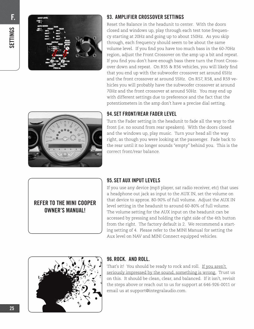
93. AMPLIFIER CROSSOVER SETTINGSReset the Balance in the headunit to center. With the doors closed and windows up, play through each test tone frequen-cy starting at 20Hz and going up to about 150Hz. As you skip through, each frequency should seem to be about the same volume level. If you find you have too much bass in the 60-70Hz region, adjust the Front Crossover on the amp up a bit and repeat. If you find you don’t have enough bass there turn the Front Cross-over down and repeat. On R55 & R56 vehicles, you will likely find that you end up with the subwoofer crossover set around 65Hz and the front crossover at around 55Hz. On R57, R58, and R59 ve-hicles you will probably have the subwoofer crossover at around 70Hz and the front crossover at around 50Hz. You may end up with different settings due to preference and the fact that the potentiometers in the amp don’t have a precise dial setting.
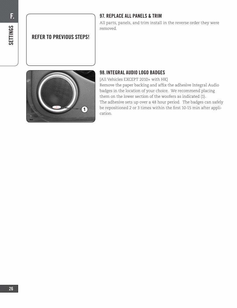
94. SET FRONT/REAR FADER LEVELTurn the Fader setting in the headunit to fade all the way to the front (i.e. no sound from rear speakers). With the doors closed and the windows up, play music. Turn your head all the way right, as though you were looking at the passenger. Fade back to the rear until it no longer sounds “empty” behind you. This is the correct front/rear balance.
95. SET AUX INPUT LEVELSIf you use any device (mp3 player, sat radio receiver, etc) that uses a headphone out jack as input to the AUX IN, set the volume on that device to approx. 80-90% of full volume. Adjust the AUX IN level setting in the headunit to around 60-80% of full volume.The volume setting for the AUX input on the headunit can be accessed by pressing and holding the right side of the 4th button from the right. The factory default is 2. We recommend a start-ing setting of 4. Please refer to the MINI Manual for setting the Aux level on NAV and MINI Connect equipped vehicles.
96. ROCK. AND ROLL.That’s it! You should be ready to rock and roll. If you aren’t seriously impressed by the sound, something is wrong. Trust us on this. It should be clean, clear, and balanced. If it isn’t, revisit the steps above or reach out to us for support at 646-926-0011 or email us at [email protected].
REFER TO THE MINI COOPER OWNER’S MANUAL!
F. SE
TTIN
GS
26
97. REPLACE ALL PANELS & TRIMAll parts, panels, and trim install in the reverse order they were removed.
98. INTEGRAL AUDIO LOGO BADGES[All Vehicles EXCEPT 2010+ with HK]Remove the paper backing and affix the adhesive Integral Audio badges in the location of your choice. We recommend placing them on the lower section of the woofers as indicated (1).The adhesive sets up over a 48 hour period. The badges can safely be repositioned 2 or 3 times within the first 10-15 min after appli-cation.
REFER TO PREVIOUS STEPS!
NOTES
27
NOTES
• AMPLIFIER TURN-ON: You will notice that the amplifier turns on before the head unit, and remains on after the head unit is off. This is normal. The sound output system needs to be energized to play your door chimes, parking distance control sounds, bluetooth, etc. The amp will turn on from the moment the doors are unlocked or opened, and remain on from between 30 seconds and as much as 20 minutes after the car is locked. Again, this is perfectly normal. The idle current on the ARC amp is virtually zero and will not cause any issues with battery drain.
• SIGNAL SOURCE QUALITY: A poor quality signal will always sound poor no matter how good an audio system is. If you are using MP3s or home-burned CDs it is critical that you understand the limitations and impacts of digital compression methods. MP3s at less than 256kbps will have noticeable loss of quality. Satellite radio is also compressed and will have similar quality issues. Non-commercially obtained music (especially downloaded via P2P file-sharing) recordings are often re-mixed by third par-ties and will have been compressed in an unknown and uncontrolled manner. If you want good quality sound, use only commercial CDs or MP3s compressed at 256kbps or 320kbps.
• FACTORY RADIO SETTINGS: Please note that the settings (Bass, Treble, Fade, Balance, AUX input level, etc.) are stored on the Key FOB & are specific to the Source (Radio, CD, AUX). You will need to edit and save the settings for each source and each FOB to have consistent sound.
• PLEASE LISTEN RESPONSIBLY: Your new Integral Audio system is capable of delivering Sound Pressure Levels that can damage your hearing. It also delivers very clean, low-distortion sound reproduction. Because distortion sounds bad to your ears, and low-distortion sounds good, you are much more likely to listen at high levels with your new system. Please exercise caution - we want you to enjoy a lifetime of great sound!
Having Trouble? The best thing to do is contact us at [email protected] or via the phone number listed on the receipt that was emailed to you. We’ll get you fixed up ASAP!
TROU
BLES
HOOT
ING