installation manual - solar vision inc
TRANSCRIPT

installation ManUal t x 3 0 0 & t x 1 5 0 c o m m e r c i a l s o l a r l i g h t i n g s y s t e m
Solar Vision inc. www.solar-vision.com [email protected] T. 1-819-729-0450
Revision 3.0
IMPORTANT: Always install the system assembly on the pole before inserting the batteries.The assembly system should never be handled when the batteries are installed inside.
LIST OF MATERIAL BY MODELTX150 SYSTEM: TX300 SYSTEM:
Battery/Control main enclosure Battery/Control main enclosureBattery, 12V (1 per system) Battery, 12V (2 per system, in series)L shape profile, 30in long (2 per system) L shape profile, 30in long (2 per system)L shape profile, 26in long (2 per system) L shape profile, 53in long (2 per system)Solar Module 150W (1 per system) Solar Module 150W (2 per system)3/8” stainless steel hardware for assembly 3/8” 5/16 stainless steel hardware for assembly5/16” stainless steel hardware for solar module assembly
5/16” stainless steel hardware for solar module assembly
LED luminaire, 12Vdc compatible LED luminaire, 24Vdc compatible2ft Elliptical tube mounting arm (Hardware not included) 2ft Elliptical tube mounting arm (Hardware not included)
Note 1: The TX150 system is a 12Vdc system with one (1) 12V battery and one (1) 150W solar module. This system is compatible with an LED luminaire operating at 12Vdc only.
Note 2: The TX300 system is a 24Vdc system with two (2) 12V batteries in series and two (2) 150W solar modules. This system is compatible with an LED luminaire operating at 24Vdc. Do not use a 12Vdc luminaire on a 24Vdc system. This will cause permanent damage to the LED driver.
TX150 System Components TX300 System Components
*Elliptical tube mounting arm and luminaire NOT shown *Elliptical tube mounting arm and luminaire NOT shown
P.1/10

installation ManUal t x 3 0 0 & t x 1 5 0 c o m m e r c i a l s o l a r l i g h t i n g s y s t e m
Solar Vision inc. www.solar-vision.com [email protected] T. 1-819-729-0450 Solar Vision inc. www.solar-vision.com [email protected] T. 1-819-729-0450
Revision 3.0
STEP 1: Using the 3/8-16 x 1¼” bolts and hardware (hex bolt, flat washer, lock washer and hex nut), tighten the two 30in “L” channels to the “main support” as indicated on the image.
STEP 2: Using the 3/8-16 x 1” bolts and hardware (hex bolt, flat washer, lock washer and hex nut), tighten the two “L” channels (26in or 53in according to model) to the “30in L channel” as indicated on the image.
TX150 FINAL ASSEMBLY TX300 FINAL ASSEMBLY
This step is identical for the TX150 & TX300
TX300TX150
P.2/10

installation ManUal t x 3 0 0 & t x 1 5 0 c o m m e r c i a l s o l a r l i g h t i n g s y s t e m
Solar Vision inc. www.solar-vision.com [email protected] T. 1-819-729-0450 Solar Vision inc. www.solar-vision.com [email protected] T. 1-819-729-0450
Revision 3.0
STEP 3: Pass through the luminaire power cable (preinstalled in the battery box) into the 90 degree connector to make it available for the luminaire connection. 10FT, #16 AWG is pre-wired.
STEP 4: 1. Determine the system’s orientation so that the solar panels are facing South.2. Once the orientation is determined, use the drilling guide at the end of the document to drill holes
at the proper location.3. Slide the system on the pole and use the 3/8”-16 x 6½” bolts and hardware to secure the system
into position. Bolts crosses the pole.
STEP 5: Using the 5/16-18 x 1” bolts and hardware (hex bolt, flat washer, lock washer and hex nut), install the solar panels using their precut frame holes.Note: The solar panel junction boxe needs to be on the down side.
TX150 TX300
TX150 TX300
P.3/10

installation ManUal t x 3 0 0 & t x 1 5 0 c o m m e r c i a l s o l a r l i g h t i n g s y s t e m
Solar Vision inc. www.solar-vision.com [email protected] T. 1-819-729-0450 Solar Vision inc. www.solar-vision.com [email protected] T. 1-819-729-0450
Revision 3.0
STEP 6: 1. For the TX300 only, make a serial connection between the solar panels, as shown in the picture
(The positive cable of one panel with the negative cable of the other panel).2. Then connect the two remaining cables to the MC4 (pre-wired) connector on the main battery com-
partment as shown on the image.
STEP 7: 1. Following the + and - (positive and negative) orientation as indicated in the battery compartment,
insert the batteries. 2. For the TX300 only, using the supplied cable, make a serial connection between the batteries
(The positive terminal of one battery with the negative terminal of the other battery).3. Then, by respecting the cable polarities, complete the batteries connection by using the pre wired
cables in the battery compartment.
TX150 TX300
TX300ONLY
P.4/10
installation ManUal t x 3 0 0 & t x 1 5 0 c o m m e r c i a l s o l a r l i g h t i n g s y s t e m
Solar Vision inc. www.solar-vision.com [email protected] T. 1-819-729-0450
Revision 3.0
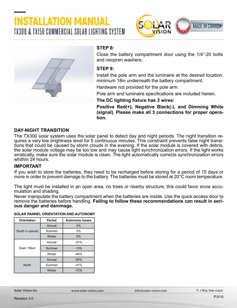
STEP 8: Close the battery compartment door using the 1/4”-20 bolts and neopren washers.
STEP 9: Install the pole arm and the luminaire at the desired location, minimum 18in underneath the battery compartment. Hardware not provided for the pole arm. Pole arm and luminaire specifications are included herein.The DC lighting fixture has 3 wires:Positive Red(+), Negative Black(-), and Dimming White (signal). Please make all 3 connections for proper opera-tion.
DAY-NIGHT TRANSITIONThe TX300 solar system uses the solar panel to detect day and night periods. The night transition re-quires a very low brightness level for 5 continuous minutes. This constraint prevents false night transi-tions that could be caused by storm clouds in the evening. If the solar module is covered with debris, the solar module voltage may be too low and may cause light synchronization errors. If the light works erratically, make sure the solar module is clean. The light automatically corrects synchronization errors whithin 24 hours.IMPORTANTIf you wish to store the batteries, they need to be recharged before storing for a period of 15 days or more in order to prevent damage to the battery. The batteries must be stored at 20°C room temperature.
The light must be installed in an open area, no trees or nearby structure, this could favor snow accu-mulation and shading.Never manipulate the battery compartment when the batteries are inside. Use the quick access door to remove the batteries before handling. Failing to follow these recommendations can result in seri-ous danger and dammage.
Orientation Period Autonomy losses
South (≈ optimal)
Annual 0%
Summer 0%
Winter 0%
East / West
Annual -21%
Summer -15%
Winter -40%
North
Annual -50%
Summer -41%
Winter -72%
SOLAR PANNEL ORIENTATION AND AUTONOMY
P.5/10

B 2
.500
1.2
50
4.0
00
TYP
. .5
00 D
ETA
IL B
SCA
LE 1
: 3
NO
TE:
The
inst
alla
tion
of th
e ba
ttery
bo
x on
the
top
of th
e la
mp
post
requ
ires d
rillin
g th
e po
st
as p
er th
e pr
esen
ted
dril
ling
pattu
rn.
The
lam
p w
ill be
se
cure
d u
sing
2 bo
lts th
roug
h th
e la
mp
post
.
Dril
l on
all 4
sid
es to
sim
plify
on
site
coo
rdin
atio
n. (S
outh
or
ient
atio
n of
the
sola
r m
odul
es.)
AA
BB
22
11
TX30
0/TX
150
5 IN
CH
POST
DRI
LLIN
G P
ATT
ERN
1D
O N
OT
SCA
LE D
RAW
ING
TX30
0/15
0-02
-EN
SHEE
T 1 O
F 1
27 J
UN 1
9
27JU
N 1
9JF
OL
JFO
L
UNLE
SS O
THER
WIS
E SP
ECIF
IED
:
SCA
LE: 1
:5W
EIG
HT:
REV
DW
G N
O.
ATITTL
E
NA
ME
DA
TE
PRO
PRIE
TARY
AN
D C
ON
FID
ENTIA
L
Q.A
.
MFG
APP
R.
ENG
APP
R.
CHE
CKE
D
DRA
WN
FIN
ISH
MA
TERI
AL
INTE
RPRE
T G
EOM
ETRI
CTO
LERA
NC
ING
PER
:
DIM
ENSI
ON
S A
RE IN
INC
HES
TOLE
RAN
CES
:A
NG
ULA
R:
1
TWO
PLA
CE
DEC
IMA
L
0.6"
THRE
E PL
AC
E D
ECIM
AL
0.
31"
HOLE
S:
0.05
"
THE
INFO
RMA
TION
CO
NTA
INED
IN T
HIS
DRA
WIN
G IS
THE
SO
LE P
ROPE
RTY
OF
SOLA
R V
ISIO
N.
AN
Y RE
PRO
DUC
TION
IN
PART
OR
AS
A W
HOLE
WITH
OUT
THE
W
RITT
EN P
ERM
ISSI
ON
OF
SOLA
R V
ISIO
N IS
PR
OHI
BITE
D.
CO
MM
ENT
SIZE
POLE
NO
T IN
CLU
DED
Teno
n dr
illin
g pa
ttern
not
sh
own
here
.
P.6/10

P.7/10
3.2
0
3.20
1.60 1.60
1.6
0 1
.60
0.35
9" TY
P.X4
1.00
"
AVA
ILA
BLE
FOR
THE
ZX60
, ZX1
00 &
ZX1
70,
FOR
SQUA
RE P
OLE
ON
LY
HARD
WA
RE 1
/4-2
0X1"
(4X)
INC
LUD
ED F
OR
INST
ALL
ING
THE
TEN
ON
PLEA
SE C
OO
RDIN
ATE
DRI
LLIN
G H
OLE
S W
ITH Y
OUR
PO
LE M
AN
UFA
CTU
RER.
TH
E FI
XTUR
E'S
TEN
ON
MUS
T BE
INST
ALL
ED A
T A
MIN
IMUM
OF
18" (
457m
m)
BELO
W T
HE T
OP
OF
THE
POST
.
PERC
EMEN
TS
DIM
ENSI
ON
S IN
INC
HES
REV
.D
ESC
RIPT
ION
DA
TEPA
R
0O
RIG
INA
L2
AO
UT 2
021
JFO
L
AA
BB
22
11
PRO
JEC
T:
WEI
GHT
:
"TH
ICKN
ESS
THE
INFO
RMA
TION
CO
NTA
INED
IN T
HIS
DRA
WIN
G IS
THE
SO
LE P
ROPE
RTY
OF
VIS
ION
SO
LAIR
E IN
C A
NY
REPR
OD
UCTIO
N IN
PA
RT O
R A
S A
WHO
LEW
ITHO
UT T
HE W
RITT
EN P
ERM
ISSI
ON
OF
VIS
ION
SO
LAIR
E C
OM
IS
PRO
HIBI
TED
.
PRO
PRIE
TARY
AN
D C
ON
FIDE
NTIA
L
DIM
ENSI
ON
S A
RE IN
INC
HES
DEF
AUL
T TO
LERA
NC
ES:
AN
GUL
AR
1°
TW
O P
LAC
E D
ECIM
AL
.0
6"TH
REE
PLA
CE
DEC
IMA
L .0
31"
HOLE
S
.0
05"
MA
TERI
AL
FIN
ISH
DRA
WN
DA
TEN
AM
EZX
- TX
TITLE
:
SIZE A
DW
G.
NO
.RE
V
SCA
LE: 1
:2
UNLE
SS O
THER
WIS
E SP
ECIF
IED
:
JFO
L2
AUG
202
1
SHEE
T 2
OF
2
TEN
SQ45
DO
NO
T SC
ALE
DRA
WIN
G
DRI
LLIN
G P
ATT
ERN
HO
RIZO
NTA
L TE
NO
N F
OR
4" &
5" S
QUA
RE P
OLE 0

SERIES-H
INSTALLATION INSTRUCTIONS
LED STREET LIGHTS
When using electrical equipment, basic safety precau�ons should alwaysbe followed including the following:
IMPORTANT SAFEGUARDS
READ AND FOLLOW ALL SAFETY INSTRUCTIONS1.
2.
3.
4.
5.
To avoid the possibility of electrical shock, turn off power supply beforeinstalla�on or servicing. Installa�on and servicing should be performedby qualied personnel. When closing cover of xture, be sure all wires are inside housing toavoid pinching wires.If Photo Receptacle is installed refer to “Photo Control” sec�on forinstruc�ons.Product must be installed in accordance with your local electrical code.If you are not familiar with these codes and requirements, consult aqualied electrician.Do not change the structure or any commponents of the xture toensure safety.
SAVE THIS INSTRUCTIONS FOR FUTURE REFERENCE
TO INSTALL:
STANDARD MOUNTING
1
H0 H10 H15
V0 V5 V15
Allen Wrench*¹2Heatsink
Cover
*¹ Allen Wrench: 4mm (5/32”)*¹ Inner Hexagon Screw: M5 (3/16”)
*² Allen Wrench: 6mm (7/32”)*² Inner Hexagon Screw: M8 (5/16”)
A
B
CAllen Wrench*²
HeatsinkCover in Open Posi�on
TerminalBlock
LED
Driv
er
Input Wires
Pole
3
Terminal Block
LED D
river
Input Wires
M16 (5/8”) waterproof connector
4 5Allen Wrench*¹
Cover
Adjust the mul�-angle �er (0, 5 ,15 degreever cal and 0, 10, 15 degree horizontal) toproper posi�on by 4mm (5/32”) allen wrench.
STEP 1:
To open cover, hold xture by heatsink withthe light modules facing down. Remove 2screws on the cover by 4mm (5/32”) allenwrench.
STEP 2:
Keep the cover in open posi�on, lead theInput Wires in through the M16 (5/8”) water-proof connector (see ), Do not �ghten. Slide xture onto pole (see ) and adjustto level posi�on. Once desired posi�on isachieved, �ghten (2) moun�ng bolts (see ).
A
B
C
STEP 3:
Connect the Input Wires into Terminal Block, Reference “Electrical Connec ons” sec�onfor comple�ng electrical connec�ons.
STEP 4:
Close the cover, �ghten (2) moun�ng bolts.STEP 5:
REV1403ALHSL-1
*Max installa�on height: 15M*Pole �er diameter: Φ 60mm (2.4”) / *48mm diameter need longer screws*This product must be grounding
P.8/10

IMPORTANTDC(Direct Current) based system.
DC BASEDSTEP 1:Make the following Electrical Connec ons:
a.
b.
Connect INPUT POSITIVE(+) conductor to RED WIRE posi on of the terminal block or POSITIVE(+) conductor of LED driver.
Connect INPUT NEGATIVE(-) conductor to BLACK WIRE posi on of the terminal block or NEGATIVE(-) conductor of LED driver.
Connect INPUT DIM SIGNAL (WHITE WIRE) to Dim signal of LED Driver.
STEP 2:Make sure all excess input wires are pushed into pole, screws are
ghtened.
STEP 3:Close cover by rmly pushing cover towards xture, making surethat no wires are pinched and Sealing gasket are fully engaged.
STEP 4:If the xture without a terminal block, please insulate all electricalconnec ons with wire nuts suitable for at least 90°C
TERMINAL BLOCK
LED D
RIVER
NEGATIVE(-) NEGATIVE(-) BLACK
POSITIVE(+) POSITIVE(+) RED+
-
INPU
T W
IRIN
G
FIXTURE WIRING
This marking indicates that this product should not be disposed with other household wastes throughout the EU.To prevent possible harm to the environment or human health from uncontrolled waste disposal, recycle itresponsibly to promote the sustainable reuse of material resources. To return your used device, please usethe return and collec on systems or contact the retailer where the product was purchased. They can takethis product for environmental safe recycling.
DIM Signal (white)
c.
DIM Signal (White)
P.9/10

FEATURES & SPECIFICATIONS
APPLICATIONFor round or square metal, aluminium or wood poles. Not for use with existing concrete poles.
CONSTRUCTIONAluminum: Body is schedule 40 (T20) aluminum pipe 6063-T6. Welding follows industry standards best practices.
INSTALLATIONMounting hardware is not included.Installer to provide hardware based on pole size and type.Note: Actual performance may differ as a result of end-user environment and application.Specifications subject to change without notice.
SPECIFICATIONS(FT)
(FT) (IN)
WALLThickness
(IN)
Progressive taper (IN)
ATTACHEMENT DETAILS
Catalog Number
Elliptical pole arm : Supplied only when part #RE2MA is added to the order. This then replaces the standard tenon indicated previously in this guide. Hardware not included for the pole arm installation. Please coordinate the hole drilling pattern with your pole supplier.
P.10/10