installation manual - viega · identified in accordance with ansi/asme a13.1. product information...
TRANSCRIPT

Installation Manual
Viega ProPress®


3 of 39IM-PP 724607 0619 ProPress
Table of Contents
Table of Contents
1 About this Document ______________________________________ 61.1 Disclaimer ____________________________________________ 61.2 Symbols Used _________________________________________ 6
2 Product Information _______________________________________ 72.1 ProPress Systems ______________________________________ 72.2 Safety ________________________________________________ 7
2.2.1 Drinking Water Installation ________________________ 72.3 Areas of Use __________________________________________ 8
2.3.1 Commercial and Residential ______________________ 92.3.2 Industrial and Plant Operations ___________________ 92.3.3 Fire Protection Systems _________________________ 92.3.4 Design Services ________________________________ 9
2.4 Product Description ____________________________________ 92.4.1 Overview ______________________________________ 92.4.2 Listings and Certifications _______________________ 102.4.3 Codes and Standards __________________________ 102.4.4 Copper Tubing ________________________________ 112.4.5 Press Fittings _________________________________ 11
2.4.5.1 Viega ProPress Fittings _________________ 112.4.5.2 Viega ProPress XL-C Fittings ____________ 112.4.5.3 EPDM Sealing Element _________________ 112.4.5.4 Cylindrical Guides______________________ 122.4.5.5 Fitting Markings _______________________ 122.4.5.6 Viega Smart Connect Technology ________ 13
2.5 General Installation Requirements ________________________ 132.5.1 Required Tools ________________________________ 132.5.2 Expansion ____________________________________ 142.5.3 Electrical Bonding _____________________________ 142.5.4 Exposure to Freezing Temperatures ______________ 142.5.5 Underground Installations _______________________ 152.5.6 Concealed Spaces ____________________________ 152.5.7 Corrosion Protection ___________________________ 15
2.5.7.1 Mixed Installations _____________________ 152.5.8 Pressure Surges _______________________________ 162.5.9 Rotating a Pressed Fitting _______________________ 162.5.10 Deflection ____________________________________ 16
2.5.10.1 Controlling Deflection ___________________ 17

4 of 39 IM-PP 724607 0619 ProPress
Table of Contents
3 Handling Instructions _____________________________________ 183.1 Transport ____________________________________________ 183.2 Storage ______________________________________________ 18
4 Installation Instructions ___________________________________ 194.1 Check System Components ____________________________ 19
4.1.1 Replacing the Sealing Element ___________________ 194.2 Installing and Mounting the Tube ________________________ 20
4.2.1 Pipe Hangers and Supports _____________________ 204.3 Space Requirements and Intervals _______________________ 20
4.3.1 Transition Fittings ______________________________ 214.3.1.1 Threaded Connections _________________ 214.3.1.2 Flange Connections ____________________ 21
4.3.2 Minimum Distance between Fittings ______________ 214.3.3 ProPress Jaws Clearance Requirements __________ 214.3.4 ProPress Rings Clearance Requirements __________ 23
4.4 Soldering or Brazing ___________________________________ 254.4.1 Using ProPress In Line with Existing Fittings _______ 254.4.2 Soldering or Brazing In Line with Existing ProPress
Fitting ________________________________________ 254.5 Welding _____________________________________________ 26
4.5.1 Welding Adjacent to a Fitting ____________________ 264.6 Cutting the Tube ______________________________________ 274.7 Deburring the Tube ____________________________________ 274.8 Pressing the Fitting ____________________________________ 28
4.8.1 Viega ProPress Installation ______________________ 284.8.2 Viega ProPress XL-C Installation _________________ 31
4.9 Pressure Testing ______________________________________ 344.10 Disposal _____________________________________________ 34
5 Limited Warranty _________________________________________ 355.1 Limited Warranty for Viega ProPress Fittings and Valves _____ 355.2 Limited Warranty for Viega Metal Systems for Industrial
Applications __________________________________________ 365.3 Limited Warranty for Viega Marine Applications ____________ 37

5 of 39IM-PP 724607 0619 ProPress
Table of Contents
List of Tables
Table 1 Fluids and water approved for use with ProPress systems ____ 8Table 2 Gases approved for use with ProPress systems ____________ 8Table 3 Minimum distance between press fittings _________________ 21Table 4 ProPress standard jaws clearance requirements ___________ 22Table 5 ProPress standard jaws clearance requirements between
tube, wall, and floor ___________________________________ 22Table 6 ProPress compact jaws clearance requirements ___________ 22Table 7 ProPress compact jaws clearance requirements between
tube, wall, and floor ___________________________________ 22Table 8 ProPress rings dimensions _____________________________ 23Table 9 ProPress rings with V1 Actuator clearance requirements ____ 23Table 10 ProPress rings with V2 Actuator clearance requirements ____ 23Table 11 ProPress rings with V1 Actuator clearance requirements
between tube, wall, and floor ___________________________ 23Table 12 ProPress rings with V2 Actuator clearance requirements
between tube, wall, and floor ___________________________ 24Table 13 ProPress rings with C1 Actuator clearance requirements
between tube, wall, and floor ___________________________ 24Table 14 ProPress XL-C rings dimensions ________________________ 24Table 15 ProPress XL-C rings clearance requirements ______________ 24Table 16 ProPress XL-C rings clearance requirements between tube,
wall, and floor ________________________________________ 24Table 17 Minimum distance between existing soldered or brazed fitting
and ProPress fitting ___________________________________ 25Table 18 Minimum distance between existing ProPress fitting and soldered
or brazed fitting _______________________________________ 26Table 19 Minimum insertion depths for ProPress ___________________ 28Table 20 Insertion depths for ProPress non-stop couplings __________ 29Table 21 Insertion depths for ProPress extended non-stop couplings _ 29Table 22 Minimum insertion depths ProPress XL-C _________________ 32Table 23 Insertion depths for ProPress XL-C non-stop couplings _____ 32

About this Document
6 of 39 IM-PP 724607 0619 ProPress
1 About this Document
DANGER!This symbol warns of possible life-threatening injury.
WARNING!This symbol warns of possible serious injury.
CAUTION!This symbol warns of possible injury.
NOTICE!This symbol warns of possible damage to property.
Notes give additional helpful tips.
1.1 Disclaimer
1.2 Symbols Used
The following symbols may be used within this document:
Viega products are designed to be installed by licensed and trained plumbing and mechanical professionals who are familiar with Viega products and their installation. Installation by non-professionals may void Viega LLC’s warranty.
This document is subject to updates. For the most current Viega technical literature please visit www.viega.us.
Product Information
7 of 39IM-PP 724607 0619 ProPress
Please read and understand the instructions before beginning installation to eliminate safety concerns and reduce risks associated with use and handling of Viega products.
Viega ProPress systems are state-of-the-art press fitting systems that provide economical and reliable installations for the commercial, industrial, and residential markets.
Viega ProPress are copper and zero lead bronze fittings and valves in copper tube size (CTS) ranging from ½ inch to 2 inches for ProPress fittings and 2½ inches to 4 inches for ProPress XL-C® (Copper) fittings. The fittings require no soldering or brazing and are installed with electro-hydraulic press tools (battery-powered or corded press tools).
The fittings feature a green dot representing Smart Connect® technology with an EPDM sealing element suitable for many applications. Viega’s unique, patented Smart Connect technology helps installers ensure that they have pressed all connections.
2 Product Information
2.1 ProPress Systems
2.2 Safety
2.2.1 Drinking Water Installation
Standard engineering practices must be observed for planning, installation, operation, and maintenance of drinking water installations.
Only EPDM sealing elements are approved in drinking water installations. The use of other sealing elements is not permitted.

Product Information
8 of 39 IM-PP 724607 0619 ProPress
The use of the system for applications other than those listed or outside of these parameters must be approved by the Viega Technical Services Department.
2.3 Areas of Use
Type of Service Comments Pressure Temperature
Hot and cold potable water 200 psi 32° to 250°F
Rainwater / gray water 200 psi 32° to 250°F
Fire sprinklers Listed with UL and FM 175 psi 32° to 250°F
Chilled water Ethylene glycol / propylene glycol
200 psi 0° to 250°F
Hydronic heating Ethylene glycol / propylene glycol
200 psi 0° to 250°F
Cooling water Up to 50% ethylene glycol or propylene glycol solution
200 psi 0° to 250°F
Low-pressure steam ≤ 15 psi max 250°F
Ethanol Pure grain alcohol 200 psi Ambient
Table 1: Fluids and water approved for use with ProPress systems
Type of Service Comments Pressure Temperature
Compressed air Oil concentrate< 25 mg/m3 200 psi 0° to 140˚F
Oxygen - O2 (nonmedical) Keep oil and fat free / non-liquid O2
140 psi 0° to 140˚F
Nitrogen - N2 200 psi 0° to 140˚F
Carbon dioxide - CO2 200 psi 0° to 140˚F
Argon Welding use 200 psi 0° to 140˚F
Hydrogen - H2 125 psi 0˚ to 140˚F
Vacuum 29.2" of Hg 0° to 160˚F
Table 2: Gases approved for use with ProPress systems
It is recommended that all systems be clearly labeled with the fluid or gas being conveyed. In the absence of local requirements, systems should be identified in accordance with ANSI/ASME A13.1.

Product Information
9 of 39IM-PP 724607 0619 ProPress
2.3.1 Commercial and Residential
ProPress systems are approved for numerous applications in commercial and residential markets including potable water. “Zero Lead” identifies products meeting the lead-free requirements of NSF 61 through testing under NSF/ANSI 372 (0.25% or less maximum weighted average lead content).
2.3.2 Industrial and Plant Operations
ProPress systems are also suitable for use in industrial and plant processes. Primary areas of application include:
■ Utility systems ■ Process piping ■ Cooling water ■ Potable water ■ Fire sprinkler systems
2.3.3 Fire Protection Systems
The system components may be installed in NFPA 13, 13R, and 13D fire sprinkler systems. They are certified for use in “wet” and “dry” fire protection systems in accordance with UL and FM certifications:
■ UL/ANSI 213: Standard for Rubber Gasketed Fittings for Fire-Protection Services.
■ ULC ORD-C213: Canadian Standard for Rubber Gasketed Fittings for Fire-Protection Services.
■ FM Class 1920: Pipe Couplings and Fittings for Aboveground Fire Protection Systems.
2.3.4 Design Services
Consult Viega’s Technical Services Department for information on applications not listed or applications outside listed temperature and pressure ranges.
■ Viega Technical Services Department: [email protected] ■ Design Service: For more information on fire protection system design,
radiant system design, and plumbing design services: [email protected]
2.4 Product Description
2.4.1 Overview
ProPress systems consists of copper and Zero Lead bronze press fittings for copper tubes and the corresponding press tools.

Product Information
10 of 39 IM-PP 724607 0619 ProPress
2.4.2 Listings and Certifications
The fittings have the following listings and certifications: ■ ABS: American Bureau of Shipping Type Approval ■ ASME B16.51: Copper and Copper Alloy Press-Connect Pressure Fittings ■ ASME B31.1: Power Piping ■ ASME B31.3: Process Piping ■ ASME B31.9: Building Service Piping ■ BV: Bureau Veritas Type Approval ■ Canadian Registration Number (CRN): 0A14541.5 A/B/C ■ CSA Low Lead Content ■ DNV GL: Det Norske Veritas Germanischer Lloyd Type Approval ■ FM Class 1920: Pipe Couplings and Fittings for Aboveground Fire
Protection Systems ■ IAPMO PS-117: Press and Nail Connections ■ ICC-ES LC1002: Copper and Copper Alloy Press-Connect Pressure Fittings ■ LR: Lloyd’s Register Type Approval ■ NFPA 13: Standard for the Installation of Sprinkler Systems ■ NFPA 13D: Standard for the Installation of Sprinkler Systems in One-
and Two-Family Dwellings and Manufactured Homes ■ NFPA 13R: Standard for the Installation of Sprinkler Systems in Low-
Rise Residential Occupancies ■ NKK: Nippon Kaija Kyokai Type Approval ■ NSF/ANSI 61: Drinking Water System Components – Health Effects ■ NSF/ANSI 372: Drinking Water System Components – Lead Content ■ UL/ANSI 213: Standard for Rubber Gasketed Fittings for Fire-
Protection Service ■ ULC/ANSI ORD-C213: Canadian Standard for Rubber Gasketed
Fittings for Fire-Protection Service
2.4.3 Codes and Standards
ProPress fittings comply with the following codes and standards: ■ ASME B31: Code for Pressure Piping ■ ASTM B88: Standard Specification for Seamless Copper Water Tube ■ IAPMO California Plumbing Code (CPC) ■ IAPMO National Standard Plumbing Code (NSPC) ■ IAPMO Uniform Mechanical Code (UMC) ■ IAPMO Uniform Plumbing Code (UPC) ■ ICC International Mechanical Code (IMC) ■ ICC International Plumbing Code (IPC) ■ ICC International Residential Code (IRC) ■ National Building Code of Canada (NBCC) ■ National Plumbing Code of Canada (NPCC)
It is the responsibility of the installer or any other parties to adhere to all applicable local rules and regulations governing the nature of the installation.

Product Information
11 of 39IM-PP 724607 0619 ProPress
2.4.4 Press Fittings
2.4.4.1 Viega ProPress Fittings
1 Each fitting contains an application specific sealing element. A green dot on a Viega ProPress fitting indicates the presence of Smart Connect technology and an EPDM sealing element.
2 Viega’s distinctive hexagonal pressing pattern bonds the fitting and tube and provides the mechanical strength for the connection.
3 Color coded dots indicate the presence of Viega’s unique, patented Smart Connect technology which helps installers ensure that they have pressed all connections.
4 Cylindrical guides ensure the proper insertion of the tube and protects the sealing element.
2.4.4.2 Viega ProPress XL-C Fittings
Viega ProPress fittings are manufactured with a high-quality, shiny black EPDM (Ethylene Propylene Diene Monomer) sealing element installed at the factory. The molded sealing lips also seal tube surfaces with slightly uneven surfaces. Sealing elements are inserted into the fitting using a H1 food grade lubricant registered with NSF and the USDA, and is approved for use under FDA 21 CFR.
The EPDM sealing element possesses excellent resistance to aging, ozone, sunlight, weathering, environmental influences, and most alkaline solutions and chemicals used in a broad range of applications.
The operating temperature of the EPDM sealing element is 0° to 250°F (-18° to 120°C).
2.4.4.3 EPDM Sealing Element
1 The 420 stainless steel grip ring's teeth bite into the tube and lock the fitting securely in place.
2 A PBT (Polybutylene Terephthalate) separator ring protects the sealing element from damage by creating a positive physical separation during installation and later during pressing.
3 The EPDM sealing element ensures water-tight or air-tight connections.
ProPress XL-C fittings are designed to be pressed with ProPress XL-C press rings and V2 actuator to produce a non-detachable, secure connection.
2.4.5 Copper Tubing
Copper and copper alloy fittings are compatible with ½ inch to 1¼ inches soft copper tubing and ½ inch to 4 inches hard copper tubing types K, L, and M. All copper tubing that is to be used must comply with ASTM B88 standards.
Copper tubing must be free of surface imperfections, including metal stamped print lines, before a ProPress fitting is installed.

Product Information
12 of 39 IM-PP 724607 0619 ProPress
Fittings are pressed before, after, and on top of the sealing element in a single step. This distinctive hexagonal pressing pattern bonds fitting and tube.
All Viega fittings are designed with cylindrical guides to keep the tube straight and protect the sealing element during assembly.
Fittings that do not have cylindrical guides risk making an unsecured connection. Without the guides, installers may damage the sealing element.
2.4.5.1 Cylindrical Guides
2.4.5.2 Fitting Markings
Each ProPress fitting is marked with the following: ■ Green dot: EPDM sealing element and Smart Connect technology ■ Size of fitting ■ Manufacturer name ■ Manufacturer date code ■ CSA®
■ NSF®-61-372 ■ UPC®
■ UL®
■ FM
Product Information
13 of 39IM-PP 724607 0619 ProPress
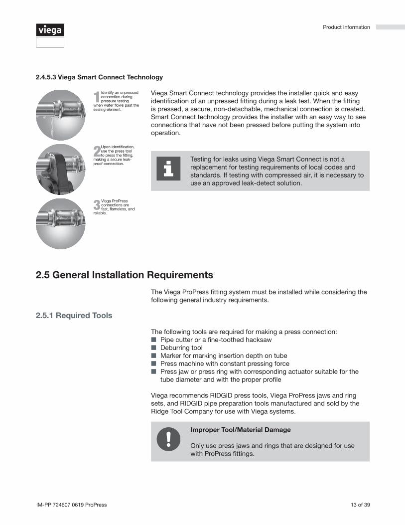
2.4.5.3 Viega Smart Connect Technology
Viega Smart Connect technology provides the installer quick and easy identification of an unpressed fitting during a leak test. When the fitting is pressed, a secure, non-detachable, mechanical connection is created. Smart Connect technology provides the installer with an easy way to see connections that have not been pressed before putting the system into operation.
Testing for leaks using Viega Smart Connect is not a replacement for testing requirements of local codes and standards. If testing with compressed air, it is necessary to use an approved leak-detect solution.
3Viega ProPress connections are fast, flameless, and
reliable.
1Identify an unpressed connection during pressure testing
when water flows past the sealing element.
2 Upon identification, use the press tool to press the fitting,
making a secure leak-proof connection.
2.5 General Installation Requirements
The Viega ProPress fitting system must be installed while considering the following general industry requirements.
2.5.1 Required Tools
The following tools are required for making a press connection: ■ Pipe cutter or a fine-toothed hacksaw ■ Deburring tool ■ Marker for marking insertion depth on tube ■ Press machine with constant pressing force ■ Press jaw or press ring with corresponding actuator suitable for the
tube diameter and with the proper profile
Viega recommends RIDGID press tools, Viega ProPress jaws and ring sets, and RIDGID pipe preparation tools manufactured and sold by the Ridge Tool Company for use with Viega systems.
Improper Tool/Material Damage
Only use press jaws and rings that are designed for use with ProPress fittings.

Product Information
14 of 39 IM-PP 724607 0619 ProPress
2.5.2 Expansion
Thermal expansion in installed systems generates stress on tubing and appliance connectors. Compensation must be allowed for expansion and contraction that may occur within the tubing. Expansion joints or mechanical expansion compensators may be used to alleviate these stresses. ProPress systems do not require any additional protection when compared to a soldered system.
The following methods are effective: ■ Fixed and sliding hangers ■ Expansion equalization joints (expansion bends) ■ Expansion compensators
2.5.3 Electrical Bonding
When properly installed, ProPress fittings comply with Section 1211.15 Electrical Bonding and Grounding of the Uniform Plumbing Code and Section 310 of the International Fuel Gas Code.
The mechanical press provides continuous metal-to-metal contact between fitting and tube. The press ensures the continuity of the bonding through this contact.
A qualified electrician is responsible for ensuring electrical bonding is tested and secured.
DANGER! Electric Shock
An electric shock can cause burns, serious injury, and even death.
■ Because all metallic tubing can conduct electricity, unintentional contact with a live wire can lead to the entire system and components connected to it to become energized. Metal piping is not meant to conduct electricity.
■ A properly bonded system creates a safe path for electricity to travel so that the system can't be energized.
■ An unbonded or improperly bonded system can be a shock hazard.
■ Always ensure bonding is in accordance with local codes.
2.5.4 Exposure to Freezing Temperatures
Viega ProPress systems with EPDM sealing elements can be installed in ambient temperatures down to 0° F. Tubing exposed to freezing temperatures must be protected per acceptable engineering practices, codes, and as required by local code.
Product Information
15 of 39IM-PP 724607 0619 ProPress
2.5.5 Underground Installations
Viega ProPress fitting systems with copper tubing are approved for underground installations. However, installations must meet all state and local codes, including those for underground. Proper authorization must be obtained prior to installation from the Authority Having Jurisdiction.
Viega ProPress fittings exposed to corrosive action, such as soil conditions or moisture, must be protected in an approved manner in accordance with NFPA 54 Section 404.8, NACE Standard RP0169-2002 Section 5, 2009 UPC Chapter 6 Section 609.3.1, 2009 UMC Chapter 13 Section 1312.1.3, or satisfying local code requirements. In addition, systems should be properly sized to minimize the risk of erosion corrosion resulting from excessive velocities.
■ In water installations, mixed metal systems can have a detrimental effect on each other and cause corrosion.
■ Copper tubing should not be installed directly upstream from galvanized steel pipe.
■ Dielectric unions should be used when connecting copper to steel or galvanized steel pipe.
■ Care should be taken to select hangers of suitable material that are galvanically compatible with the tubing.
Above ground copper tubing and fittings do not normally require external corrosion protection with the following exceptions:
■ Contact with aggressive building materials such as nitrite or materials containing ammonium.
■ In aggressive environments.
Please contact the Viega Technical Services Department for questions on this subject.
The flow rule must be observed in all mixed installations with tubing made of copper and pipes made of galvanized steel.
2.5.6 Concealed Spaces
The Viega ProPress fitting system has been approved for use in concealed spaces. Specific performance tests were conducted to evaluate the fittings for use in concealed spaces. Concealed tubing and fittings shall be protected from puncture threats.
2.5.7 Corrosion Protection
2.5.7.1 Mixed Installations

Product Information
16 of 39 IM-PP 724607 0619 ProPress
2.5.8 Pressure Surges
■ Pressure surges or transients from fast-acting valves, pump surges, and other sources that result in water hammer may cause damage to many system components, including press fittings.
■ When fast-acting valves and/or pumps are incorporated into a system, the designer and installer should isolate press fittings from sharp pressure surges.
2.5.9 Rotating a Pressed Fitting
Once a ProPress fitting has been pressed, it can be rotated (not by hand), but once rotated more than five degrees, the fitting should be repressed to restore resistance to rotational movement.
If the fitting is re-pressed, care should be taken to align the flat sides on the jaw with those on the fitting.
2.5.10 Deflection
The pressing process can cause deflection (angular misalignment) to occur. When pressing Viega ProPress fittings in a system, the deformation of the fitting is constant. This allows for a consistent leak-free joint every time and is a result of the pressing technique.
Deflection occurs in the same way for every fitting. The fitting being pressed will move in the direction of the jaw or ring opening.
■ Since the fitting will deflect toward the opening of the jaw or ring, the tube end will deflect in the opposite direction.
■ By counteracting the fitting movement, one can minimize the deflection of the fitting and ultimately the tube.
■ When using strut and clamps, deflection is minimized and nearly eliminated depending on clamp spacing.
■ ProPress fittings should be isolated or separated by sufficient distance from pumps, fast-acting valves, and other sources of pressure transients.
■ The maximum operating pressure in a ProPress system is 200 psi, which applies to general operation as well as pressure transients.
■ Good engineering practices should be used to design the system in a way that minimizes sharp pressure surges.

Product Information
17 of 39IM-PP 724607 0619 ProPress
■ As long as the tube is properly prepped and marked and the fitting is installed according to Viega’s ProPress Product Instructions, if there is any deflection present after the installation of the fitting, the connection is still acceptable and meets Viega’s manufacturing specifications for proper installation and warranty.
■ Deflection of a press connection has no effect on the integrity of the system, and it can be pressure tested in accordance with the ProPress Product Instructions.
Push-pull method ▶ Rings = Push on press tool. ▶ Jaws = Pull on press tool.
The press tool can be feathered using the trigger as needed to apply pulling or pushing force to control deflection.
2.5.10.1 Controlling Deflection
Deflection while pressing can be minimized by utilizing the following installation practices.
Alternate sides for presses ▶ Press one end of fitting. ▶ Make second press on other end of fitting from the opposite side.
Site conditions permitting.
Re-Press ▶ Press the fitting, once on each side (that is, re-press the fitting a
second time on the opposite side). Pressing the same connection from the opposite side will usually straighten misalignment between the tube and fitting.
■ When pressing overhead piping, it may be inconvenient to alternate sides for each press.
■ The natural weight of the piping plus pressing on opposite sides at a 45 degree angle should adequately eliminate deflection.
■ This technique can also be used for any horizontal piping and also when working above the piping.
Handling Instructions
18 of 39 IM-PP 724607 0619 ProPress
All Viega ProPress components and associated tubing shall be free from dirt, debris, or items that may interfere with the sealing element and the press connection. Viega ProPress sealing elements, separator rings, and grip rings are to be visually inspected prior to installation to ensure the seal is intact and properly located within the fitting.
3 Handling Instructions
3.1 Transport
When transporting fittings: ■ Do not pull or drag the fittings or system components along other
surfaces. ■ Secure fittings, tubing, and system components during transportation
to keep them from shifting. ■ Do not damage the protective cap on components or tube ends. ■ Do not remove protective caps until immediately before installing.
3.2 Storage
When storing materials: ■ Store fittings, tubing, and system components in a clean and dry
place. ■ Do not store components directly on the floor. ■ Provide at least three points of support for the storage of tubing. ■ Where possible, store different sizes separately. ■ Store small sizes on top of larger sizes if separate storage is not
possible. ■ Store fittings, tubing, and system components of different materials
separately to prevent contact corrosion.

Installation Instructions
19 of 39IM-PP 724607 0619 ProPress
System components may, in some cases, become damaged through transportation and storage.
■ Check all parts. ■ Replace damaged components. ■ Do not repair damaged components. ■ Contaminated components may not be installed.
4 Installation Instructions
4.1 Check System Components
4.1.1 Replacing the Sealing Element
Damage to the Sealing Element
If damage to the sealing element, separator ring, or grip ring is discovered, contact a Viega District Manager for assistance.
Do not use metallic pointed or sharp objects during removal because they could damage the sealing element and/or bead. Try using a toothpick instead.
If the sealing element in the fitting is obviously damaged, it should be exchanged for a Viega replacement sealing element.
▶ Insert new, undamaged sealing element into the bead.
▶ Check to make sure that the whole sealing element is in the bead.
▶ Remove the sealing element from the bead.

Installation Instructions
20 of 39 IM-PP 724607 0619 ProPress
4.2 Installing and Mounting the Tube
Observe the general rules of hanging and mounting: ■ Fixed tubing should not be used as support for other tubing and
components. ■ Do not use pipe hooks. ■ Observe distance between fittings and mounting points. ■ Observe the expansion direction – plan fixed and sliding mounts.
4.2.1 Pipe Hangers and Supports
Tubing supports perform two functions: ■ To provide support for the tubing. ■ To guide the tube during thermal expansion and contraction.
Fittings must not be used as support
■ System malfunction may result from additional stress and strain put on the fitting.
■ At no point in the system should a fitting be the sole means of support. For example, when installing a tee, both the branch and the trunk must be properly supported.
Industry standard practices and guidelines shall be used for tube layout and support. Viega press connections require no special consideration for support.
Hangers and supports must conform to the local code requirements. In the absence of local code requirements, hangers and supports should conform to ANSI/MSS SP 58 Pipe Hangers and Supports - Materials, Design, Manufacture, Selection, Application and Installation.
4.3 Space Requirements and Intervals
Not enough space
The connection may leak and/or ring/press gun may not fit around the fitting.
■ Adhere to minimum space requirements. ■ Make sure that the space required for pressing tools is available if fittings will be pressed immediately upstream or downstream from wall or ceiling penetrations.
■ Take the minimum required distances into consideration during the planning phase of the project whenever possible.

Installation Instructions
21 of 39IM-PP 724607 0619 ProPress
4.3.1 Transition Fittings
4.3.1.1 Threaded Connections
The Viega ProPress systems can be joined with off-the-shelf threaded fittings made of non-ferrous metals.
In this regard: ■ The threaded connection is made first. ■ The press connection is made second.
This process avoids unnecessary torsion on the press fitting.
4.3.1.2 Flange Connections
When using Viega flanges, bolt the flange end in place prior to pressing the fitting to the tube.
4.3.2 Minimum Distance between Fittings
To ensure a correct press, a minimum distance between press fittings must be maintained. Failure to provide this distance may result in an improper seal.
For installations where the minimum distance is zero, it is particularly important to ensure the correct insertion depth of the tube into each fitting.
Tube Diameter (inches) A minimum (inches) A minimum (mm)
½
0 0¾
1
1¼ 7/16 10
1½ ⅝ 15
2 ¾ 20
2½
⅝ 153
4
Table 3: Minimum distance between press fittings
minimumdistance
4.3.3 ProPress Jaws Clearance Requirements
The minimum distance between tube, or the tube and the wall/ceiling construction, must be taken into consideration in the planning phase for a problem free work process. The following illustrate the clearance requirements for the jaws and fittings and the procedure for pressing fittings in tight quarters.
Tubing installed too closely together
Connection may leak ■ Adhere to minimum intervals between fittings. ■ Insert tube to full insertion depth before pressing.

Installation Instructions
22 of 39 IM-PP 724607 0619 ProPress
Tube Diameter (inches)
A minimum (inches)
A minimum (mm)
B minimum (inches)
B minimum (mm)
½ ¾ 19 1⅝ 41
¾ ⅞ 22 2⅛ 54
1 1 26 2½ 64
1¼ 1⅛ 29 2⅞ 73
1½ 1¾ 45 3½ 89
2 2 51 4⅜ 111
Table 4: ProPress standard jaws clearance requirements
Tube Diameter (inches)
A minimum (inches)
A minimum
(mm)
B minimum (inches)
B minimum
(mm)
C minimum (inches)
C minimum
(mm)
½ ⅞ 23 1 ⅜ 35 2 ½ 64
¾ 1 26 1 ½ 38 2 ½ 64
1 1 ⅛ 29 1 ¾ 45 3 76
1 ¼ 1 ¼ 32 2 ¼ 57 3 ⅛ 80
1 ½ 1 ⅞ 48 2 ½ 64 3 ¾ 95
2 2 ⅛ 54 3 ⅛ 80 5 127
Table 5: ProPress standard jaws clearance requirements between tube, wall, and floor
Tube Diameter (inches)
A minimum (inches)
A minimum (mm)
B minimum (inches)
B minimum (mm)
½ ¾ 19 2 51
¾⅞
22 2⅜ 60
1 26 2⅝ 67
1¼ 1⅛ 28 3⅛ 85
Table 6: ProPress compact jaws clearance requirements
Tube Diameter (inches)
A minimum (inches)
A minimum
(mm)
B minimum (inches)
B minimum
(mm)
C minimum (inches)
C minimum
(mm)
½ ⅞ 23 1⅜ 35 2½ 64
¾ 1 26 1½ 38 2¾ 70
1 1⅛ 29 1⅝ 41 3 76
1¼ 1⅝ 39 2⅛ 53 3⅜ 85
Table 7: ProPress compact jaws clearance requirements between tube, wall, and floor
A
B
A
B
C
20°
A
B
A
B
C
20°

Installation Instructions
23 of 39IM-PP 724607 0619 ProPress
4.3.4 ProPress Rings Clearance Requirements
Ensure that the space required for system pressing tools is available if Viega ProPress fittings will be installed immediately upstream or downstream from ceiling penetrations.
Tube Diameter (inches)
A minimum (inches)
A minimum
(mm)
B minimum (inches)
B minimum
(mm)
C minimum (inches)
C minimum
(mm)
½ 2¼ 57 2⅛ 54 11/16 27
¾ 211/16 68 2⅞ 73 1⅛ 28
1 215/16 75 35/16 84
13/16 301¼ 35/16 84 3⅞ 99
1½ 311/16 94 45/16 110
2" 47/16 113 57/16 139
Table 8: ProPress rings dimensions
Tube Diameter(inches)
A minimum (inches)
A minimum (mm)
B minimum (inches)
B minimum (mm)
½ 1⅝ 41 23/16 71
¾ 1¾ 45 23/16 55
1 2 51 1⅝ 42
1¼ 23/16 55 215/16 75
Table 9: ProPress rings with V1 Actuator clearance requirements
Tube Diameter(inches)
A minimum (inches)
A minimum (mm)
B minimum (inches)
B minimum (mm)
1½ 2⅜ 60 35/16 85
2 29/16 65 4⅛ 105
Table 10: ProPress rings with V2 Actuator clearance requirements
Tube Diameter (inches)
A minimum (inches)
A minimum
(mm)
B minimum (inches)
B minimum
(mm)
C minimum (inches)
C minimum
(mm)
½ 1⅝ 41 39/16 90 25/16 59
¾ 1¾ 45 3⅝ 92 2⅛ 55
1 2 51 313/16 97 23/16 56
1¼ 23/16 55 3¾ 92 2⅛ 55
Table 11: ProPress rings with V1 Actuator clearance requirements between tube, wall, and floor
A
B
C

Installation Instructions
24 of 39 IM-PP 724607 0619 ProPress
Tube Diameter (inches)
A minimum (inches)
A minimum
(mm)
B minimum (inches)
B minimum
(mm)
C minimum (inches)
C minimum
(mm)
1½ 2⅜ 60 5 127 23/16 56
2 29/16 65 4¾ 121 39/16 65
Table 12: ProPress rings with V2 Actuator clearance requirements between tube, wall, and floor
Tube Diameter (inches)
A minimum (inches)
A minimum
(mm)
B minimum (inches)
B minimum
(mm)
C minimum (inches)
C minimum
(mm)
½ 1⅝ 41
3¼ 83
2 51
¾ 1¾ 45
1⅞ 481 2 51
1¼ 23/16 55 3⅜ 86
Table 13: ProPress rings with C1 Actuator clearance requirements between tube, wall, and floor
Tube Diameter (inches)
A minimum (inches)
A minimum
(mm)
B minimum (inches)
B minimum
(mm)
C minimum (inches)
C minimum
(mm)
2½ 63/16 157 615/16 176
27/16 623 77/16 189 813/16 224
4 81/16 205 10 7/16 265
Table 14: ProPress XL-C rings dimensions
Tube Diameter (inches)
A minimum (inches)
A minimum (mm)
B minimum (inches)
B minimum (mm)
2½ 4⅛ 105 6 152
3 4⅜ 111 7 178
4 5 127 8 203
Table 15: ProPress XL-C rings clearance requirements
Tube Diameter (inches)
A minimum (inches)
A minimum
(mm)
B minimum (inches)
B minimum
(mm)
C minimum (inches)
C minimum
(mm)
2½ 4⅛ 105 6 152 4½ 114
3 4⅜ 111 7 178 4⅞ 124
4 5 127 8 203 5¾ 146
Table 16: ProPress XL-C rings clearance requirements between tube, wall, and floor
B
A
B
C
A
B

Installation Instructions
25 of 39IM-PP 724607 0619 ProPress
■ The minimum clearance requirement when pressing connections near an existing brazed connection is two tube diameters.
■ To ensure proper sealing of both the soldered and press connections, a minimum distance when pressing connections near an existing soldered fitting must be maintained.
Refer to the table below.
4.4 Soldering or Brazing
4.4.1 Using ProPress In Line with Existing Fittings
Check the fitting to make sure there is no residual solder or other foreign debris on the tube that will be inserted into the Viega ProPress fitting.
To prevent damage to the sealing element and ensure proper sealing of the soldered/brazed joint and the press connection, maintain proper soldering/brazing distances from the fitting:
■ When soldering near a ProPress connection: three tube diameters. ■ When brazing near a ProPress connection: nine tube diameters.
Refer to the following table.
4.4.2 Soldering or Brazing In Line with Existing ProPress Fitting
Tube Diameter (inches)
Minimum distance from
Soldered (inches)
Minimum distance from Soldered (mm)
Minimum distance from
Brazed (inches)
Minimum distance from Brazed (mm)
½ ¼ 7 1 26
¾ ¼ 7 1½ 38
1 7/16 11 2 51
1¼ 7/16 11 2½ 64
1½ ⅝ 16 3 76
2 ¾ 19 4 102
2½ ¼ 7 5 127
3 ¼ 7 6 153
4 ¼ 7 8 204
Table 17: Minimum distance between existing soldered or brazed fitting and ProPress fitting

Installation Instructions
26 of 39 IM-PP 724607 0619 ProPress
Tube Diameter (inches)
Soldering minimum
distance (inches)
Soldering minimum
distance (mm)
Brazing minimum distance (inches)
Brazing minimum distance (mm)
½ 1½ 38 4½ 114
¾ 2¼ 57 6¾ 172
1 3 76 9 229
1¼ 3¾ 95 11¼ 286
1½ 4½ 114 13½ 343
2 6 153 18 457
2½ 7½ 191 22½ 572
3 9 229 27 686
4 12 305 36 915
Table 18: Minimum distance between existing ProPress fitting and soldered or brazed fitting
The installer should take precautions to keep the Viega ProPress connection cool:
■ Wrap the connection with a cold wet rag. ■ Protect the connection with a weld blanket. ■ Prefabricate solder connections/welded fittings prior to installing the
press fitting. (Ensure tube has cooled before installing the fitting). ■ Apply heat sink gel or spray or spot freezing
4.5 Welding
To prevent damage to the sealing element, maintain proper welding distances from the fitting. If welding adjacent to the connection, weld a minimum of four inches away.
Installers should follow the precautions listed above to keep the Viega ProPress connection cool.
4.5.1 Welding Adjacent to a Fitting

Installation Instructions
27 of 39IM-PP 724607 0619 ProPress
▶ Cut the tube square using a displacement-type cutter or fine toothed saw.
Note: Cut tubing a minimum of four inches away from the contact area of the vise to prevent possible damage to the tubing in the press area.
4.6 Cutting the Tube
Damaged tube and/or sealing element
Press fittings can form improper connections as the result of damaged tube and/or sealing elements.
■ Do not use flame cutters when cutting the tube. ■ Do not use grease or oils when cutting the tube.
4.7 Deburring the Tube
Damage resulting from the wrong deburring tool
■ Connections may leak if they are damaged by improper deburring.
■ Failure to deburr tubing will reduce the service life of the system and can cause premature leaks.
The tube ends must be thoroughly deburred after cutting. Damage to or twisting of the sealing element during installation is prevented by deburring.
▶ Deburr inside and outside of the tube to the proper insertion depths.
▶ Use a wire brush, Scotchbrite pad, sand cloth, or sandpaper to remove loose dirt and rust particles from the pressing area.
Avoid cutting through grooves, manufacturer’s stamps, or engravings on the tube surface.

Installation Instructions
28 of 39 IM-PP 724607 0619 ProPress
For Types K, L, and M Hard Copper Tubing in ½ inch to 2 inches and Soft Copper Tubing in ½ inch to 1¼ inches.
▶ Check the sealing element for correct fit: ■ The tube end is not bent or damaged. ■ The tube is deburred. ■ The correct sealing element (EPDM) is in the fitting. ■ The sealing element is undamaged. ■ The complete sealing element is in the bead.
4.7.1 Viega ProPress Installation
▶ Measure insertion depth (see table below).
▶ Mark the proper insertion depth on the outside of the tube.
Improper insertion depth
Improper insertion depth may result in an improper seal. ■ Be sure to mark the correct insertion depth on the tube before pressing the fitting.
Tube Diameter (inches) Insertion Depth (inches)
½ ¾
¾ ⅞
1 ⅞
1¼ 1
1½ 17/16
2 19/16
Table 19: Minimum insertion depths for ProPress
4.8 Pressing the Fitting
WARNING! Read and understand all instructions for installing Viega ProPress fittings. Failure to follow all instructions may result in extensive property damage, serious injury, or death.

Installation Instructions
29 of 39IM-PP 724607 0619 ProPress
Tube Diameter (inches)
Minimum Insertion
Depth (inches)
Minimum Insertion
Depth (mm)
Maximum Insertion
Depth (inches)
Maximum Insertion
Depth (mm)
½ ¾ 19 ⅞ 22
¾ ⅞ 23 1⅛ 28
1 ⅞ 23 1⅛ 28
1¼ 1 26 13/16 30
1½ 17/16 37 19/16 40
2 19/16 40 1¾ 44
Table 20: Insertion depths for ProPress non-stop couplings
Non-stop couplings and extended non-stop couplings are often used to conduct repairs. Without a stop, these couplings can slide completely onto a tube and allow a connection to be made in tighter spaces. Unlike fittings with an integrated stop that have a minimum insertion depth, non-stop couplings have minimum and maximum allowable insertion depths. Both the minimum and the maximum insertion depths must be marked and a line connecting the two marks. Drawing a line between the minimum and maximum insertion marks distinguishes a good connection on a non-stop fitting from a bad connection on a fitting with a stop.
Tube Diameter (inches)
Minimum Insertion
Depth (inches)
Minimum Insertion
Depth (mm)
Maximum Insertion
Depth (inches)
Maximum Insertion
Depth (mm)
½ ¾ 19 2¼ 57
¾ ⅞ 23 2⅝ 67
1 ⅞ 23 2⅞ 73
1¼ 1 26 3⅛ 80
1½ 17/16 37 35/16 84
2 19/16 40 3¾ 95
Table 21: Insertion depths for ProPress extended non-stop couplings
▶ While turning slightly, slide press fitting onto the tube to the marked insertion depth.
Note: End of tube must contact stop.

Installation Instructions
30 of 39 IM-PP 724607 0619 ProPress
▶ Pull retaining pin out of press tool.
▶ Insert appropriate jaw.
▶ Push in retaining pin until it locks the jaw in place.
▶ Open the jaw and place at right angle on the fitting.
▶ Look at insertion depth mark on the tube to make sure that the tube is properly inserted into the fitting.
▶ Hold trigger on press tool until press jaws have fully engaged the fitting. Jaws will automatically release after a full press is made.
▶ After pressing, open the jaws.
▶ Remove the press tool.
▷ Fitting is securely pressed.
WARNING!
Keep extremities and foreign objects away from press tool during pressing operation to prevent injury or incomplete press.

Installation Instructions
31 of 39IM-PP 724607 0619 ProPress
For Types K, L, and M Hard Copper Tubing in 2½ inches to 4 inches.
4.8.1 Viega ProPress XL-C Installation
WARNING! Read and understand all instructions for installing Viega ProPress XL-C (Copper) fittings. Failure to follow all instructions may result in extensive property damage, serious injury, or death.
Use only rings that are compatible with ProPress XL-C fittings.
■ Use of incompatible rings will result in an improper connection.
■ Do not mix actuators and rings from different manufacturers.
■ Do not use rings intended for XL Bronze fittings.
▶ Check the sealing element, separator ring, and grip ring for correct fit: ■ The tube end is not bent or damaged. ■ The tube is deburred. ■ The correct sealing element (EPDM) is in the fitting.
Illustration demonstrates proper fit of grip ring, separator ring, and sealing element.

Installation Instructions
32 of 39 IM-PP 724607 0619 ProPress
Tube Diameter (inches) Insertion Depth (inches)
2½ 111/16
3 115/16
4 2⅜
Table 22: Minimum insertion depths ProPress XL-C
▶ Measure insertion depth (see table below). ▶ Mark the proper insertion depth on the outside of the tube.
Improper insertion depth
Improper insertion depth may result in an improper seal. ■ Be sure to mark the correct insertion depth on the tube before pressing the fitting.
Tube Diameter (inches)
Minimum Insertion
Depth (inches)
Minimum Insertion
Depth (mm)
Maximum Insertion
Depth (inches)
Maximum Insertion
Depth (mm)
2½ 111/16 43 2⅝ 67
3 115/16 50 215/16 75
4 2⅜ 60 37/16 87
Table 23: Insertion depths for ProPress XL-C non-stop couplings
Non-stop couplings and extended non-stop couplings are often used to conduct repairs. Without a stop, these couplings can slide completely onto a tube and allow a connection to be made in tighter spaces. Unlike fittings with an integrated stop that have a minimum insertion depth, non-stop couplings have minimum and maximum allowable insertion depths. Both the minimum and the maximum insertion depths must be marked and a line connecting the two marks. Drawing a line between the minimum and maximum insertion marks distinguishes a good connection on a non-stop fitting from a bad connection on a fitting with a stop.
▶ While turning slightly, slide fitting onto the tube to marked insertion depth.
Note: End of tube must contact stop.

Installation Instructions
33 of 39IM-PP 724607 0619 ProPress
▶ Open XL-C ring and place at right angles on the fitting.
▶ Ensure that the XL-C ring is engaged on the fitting bead.
▶ Open the V2 Actuator and connect the V2 Actuator to the XL-C ring.
▶ Look at insertion depth mark on the tube to make sure that the tube is properly inserted into the fitting.
▶ Hold the trigger until the Actuator has engaged the XL-C ring.
WARNING!
Keep extremities and foreign objects away from XL-C ring and V2 Actuator during pressing operation to prevent injury or incomplete press.
▶ Release the V2 Actuator from XL-C ring.
▶ Remove the XL-C ring from fitting upon completion of the press.
▶ Remove product instruction label from fitting to indicate that press has been completed.

Installation Instructions
34 of 39 IM-PP 724607 0619 ProPress
4.9 Pressure Testing
Viega Smart Connect technology provides a quick and easy way for installers to identify connections that need to be pressed. Unpressed connections are located by pressurizing the system with air or water.
Pressure test all installed tube in accordance with local codes.
Smart Connect Testing ■ Testing for unpressed connections using Smart Connect is not a replacement for pressure testing requirements of local codes and standards.
■ If testing with compressed air, use an approved leak-detect solution.
Water testing with Viega Smart Connect: ■ Use a range of 15 to 85 psi. ■ If an unpressed fitting is found, make sure the tube is fully inserted
before completing the press. ■ If the initial test is successful, system may be pressure tested as
required up to 600 psi.
Testing with air can be dangerous at high pressures. When air testing with Viega Smart Connect:
■ Use a range of ½ psi to 45 psi. ■ If an unpressed fitting is found, make sure the tube is fully inserted
before completing the press. ■ If the initial test is successful, system may be pressure tested as
required up to 200 psi.
4.10 Disposal
Separate the product and packaging materials (e.g. paper, metal, plastic, non-ferrous metals) and dispose in accordance with all national, state, and regional requirements.

Limited Warranty
35 of 39IM-PP 724607 0619 ProPress
Subject to the conditions and limitations in this Limited Warranty, Viega LLC (VIEGA) warrants to wholesalers and licensed plumbing and mechanical contractors in the United States and Canada that its ProPress fittings, when properly installed in non-industrial and non-marine applications and under normal conditions of use, will be free of failure from manufacturing defect for a period of fifty (50) years from date of installation and that its ProPress valves, when properly installed in non-industrial and non-marine applications and under normal conditions of use, will be free of failure from manufacturing defect for a period of two (2) years from date of installation.
Under this Limited Warranty, you only have a right to a remedy if the failure or leak resulted from a manufacturing defect in the products covered by this warranty and the failure or leak occurred during the warranty period. You do not have a remedy under this warranty and the warranty does not apply if the failure or any resulting damage is caused by (1) components other than those manufactured or sold by Viega; (2) not designing, installing, inspecting, or testing the ProPress fittings or valves in accordance with Viega’s installation instructions in effect at the time of the installation; applicable code requirements; and accepted industry practice; (3) improper handling and protection of the product prior to and during installation, inadequate freeze protection, exposure to water pressures or temperatures or in applications outside acceptable operating conditions; (4) acts of nature such as, but not limited to, earthquakes, fire, flood, or lightning, or (5) external environmental causes, such as water quality variations, aggressive water, or other external chemical or physical conditions.
In the event of a leak or other failure of the parts covered by this warranty, it is the responsibility of the property owner to obtain and pay for repairs. Only if the warranty applies will Viega be responsible for the remedy under this warranty. The part or parts which you claim failed should be kept and Viega contacted by writing to the address below or telephoning 1-800-976-9819 within thirty (30) days after the leak or other failure and identifying yourself as having a warranty claim. You should be prepared to ship, at your expense, the product which you claim failed due to a manufacturing defect and document the date of installation. Within a reasonable time after receiving the product, Viega will investigate the reasons for the failure, which includes the right to inspect the product at Viega. Viega will notify you in writing of the results of its review.
In the event that Viega determines that the failure or leak as the result of a manufacturing defect in the part covered by this warranty and that this warranty applies, the EXCLUSIVE AND ONLY REMEDY under this warranty shall be the reimbursement for repair and/or replacement of
5 Limited Warranty
5.1 Limited Warranty for Viega ProPress Fittings and Valves

Limited Warranty
36 of 39 IM-PP 724607 0619 ProPress
the part. VIEGA SHALL NOT BE LIABLE FOR ANY CONSEQUENTIAL OR OTHER DAMAGE (FOR EXAMPLE, WATER OR PROPERTY OR MOLD REMEDIATION) UNDER ANY LEGAL THEORY AND WHETHER ASSERTED BY DIRECT ACTION, FOR CONTRIBUTION OR INDEMNITY OR OTHERWISE.
THE ABOVE WARRANTY IS IN LIEU OF ALL OTHER WARRANTIES, EXPRESS OR IMPLIED, INCLUDING BUT NOT LIMITED TO THE IMPLIED WARRANTIES OF MERCHANTABILITY AND FITNESS FOR A PARTICULAR PURPOSE. If a limited warranty shall be found to apply, such warranty is limited to four years. Other than this Limited Warranty, Viega does not authorize any person or firm to create for it any other obligation or liability in connection with its products.
This Limited Warranty gives you specific legal rights and you also may have other rights which may vary from state to state. This warranty shall be interpreted and applied under the law of the state in which the product is installed and is intended as a Commercial Warranty.
5.2 Limited Warranty for Viega Metal Systems for Industrial Applications
Industrial applications are defined as non-residential and non-commercial applications not normally accessible to the general public, including manufacturing, mining, process or fabrication environments.
Subject to the terms and conditions of this Limited Warranty, Viega LLC (Viega) warrants to end users, installers and distribution houses that its Viega metal press products (Viega product) when properly installed in industrial applications shall be free from failure caused by manufacturing defects for a period of two (2) years from date of installation.
Under this Limited Warranty, you only have a right to a remedy if the failure or leak resulted from a manufacturing defect in the Viega product and the failure or leak occurs during the warranty period. You do not have a remedy under this warranty and the warranty remedy does not apply if the failure or any resulting damage is caused by (1) components other than those sold by Viega; (2) not designing, installing, inspecting, testing, or maintaining the Viega product in accordance with Viega’s installation and product instructions in effect at the time of installation and other specifications and approvals applicable to the installation; (3) improper handling and protection of the Viega product prior to, during and after installation, inadequate freeze protection, or exposure to environmental or operating conditions not recommended for the application; or (4) acts of nature, such as, but not limited to earthquakes, fire, or weather damage. Final approval as to use compatibility to a specific process or fluid application is the responsibility of the engineer of record or responsible design/facilities personnel and this Limited Warranty only applies to manufacturing defects in the Viega Product.
In the event of a leak or other failure in the Viega product covered by this warranty, it is the responsibility of the end user to take appropriate measures to diminish any damage, to include making timely repairs. Only if the warranty applies will Viega be responsible for the remedy under this

Limited Warranty
37 of 39IM-PP 724607 0619 ProPress
warranty. The part or parts which you claim failed should be kept and Viega contacted by writing to the address below or telephoning 1-800-976-9819 within thirty (30) calendar days after the leak or other failure and identifying yourself as having a warranty claim. You should be prepared to ship, at your expense, the product which you claim failed due to a manufacturing defect, document the date of installation, and the amount of the repair or replacement if performed by you. Within a reasonable time after receiving the product, Viega will investigate the reasons for the failure, which includes the right to inspect the product at a Viega location and reasonable access to the site of damage. Viega will notify you in writing as to the results of its review.
In the event that Viega determines that the failure or leak was the result of a manufacturing defect in the Viega Product covered by this warranty and to which this warranty applies, the EXCLUSIVE AND ONLY REMEDY under this warranty shall be the reimbursement for reasonable charges for repair or replacement of the Viega Product itself. VIEGA SHALL NOT BE LIABLE FOR CONSEQUENTIAL OR OTHER DAMAGE (FOR EXAMPLE, ECONOMIC LOSS, WATER OR PROPERTY OR MOLD REMEDIATION) UNDER ANY LEGAL THEORY AND WHETHER ASSERTED BY DIRECT ACTION, FOR CONTRIBUTION OR INDEMNITY OR OTHERWISE.
THE ABOVE WARRANTY IS IN LIEU OF ALL OTHER WARRANTIES, EXPRESS OR IMPLIED, INCLUDING, BUT NOT LIMITED TO, THE IMPLIED WARRANTIES OR ANY STATUTE OF LIMITATIONS RELATING TO SUCH WARRANTIES. Other than this Limited Warranty, Viega does not authorize any person or firm to create for it any other obligation or liability in connection with its products.
This Limited Warranty gives you specific legal rights and you also may have other rights which may vary from state to state. This warranty shall be interpreted and applied under the law of the state in which the product is installed and is intended as a Commercial Warranty.
5.3 Limited Warranty for Viega Marine Applications
Marine applications are defined as mobile structures used to navigate water or stationary structures in water.
Subject to the terms and conditions of this Limited Warranty, Viega LLC (Viega) warrants to end users, installers and distribution houses that its Viega metal press products (Viega product) when properly installed in approved marine applications and other products sold by Viega LLC when properly installed in marine applications in accordance with our listings shall be free from failure caused by manufacturing defects for a period of two (2) years from date of installation. This warranty applies only to approved applications. Installations that are not approved shall not be covered by this warranty and shall not be the responsibility of Viega LLC.
Under this Limited Warranty, you only have a right to a remedy if the failure or leak resulted from a manufacturing defect in the Viega product and the failure or leak occurs during the warranty period. You do not have a remedy under this warranty and the warranty remedy does not apply

Limited Warranty
38 of 39 IM-PP 724607 0619 ProPress
if the failure or any resulting damage is caused by (1) components other than those sold by Viega; (2) not designing, installing, inspecting, testing, or maintaining the Viega product in accordance with Viega’s installation and product instructions in effect at the time of installation and other specifications and approvals applicable to the installation; (3) improper handling and protection of the Viega product prior to, during and after installation, inadequate freeze protection, or exposure to environmental or operating conditions not recommended for the application; or (4) acts of nature, such as, but not limited to earthquakes, fire, or weather damage. Final approval as to use compatibility to a specific process or fluid application is the responsibility of the engineer of record or responsible design/facilities personnel and this Limited Warranty only applies to manufacturing defects in the Viega Product.
In the event of a leak or other failure in the Viega product covered by this warranty, it is the responsibility of the end user to take appropriate measures to diminish any damage, to include making timely repairs. Only if the warranty applies will Viega be responsible for the remedy under this warranty. The part or parts which you claim failed should be kept and Viega contacted by writing to the address below or telephoning 1-800-976-9819 within thirty (30) calendar days after the leak or other failure and identifying yourself as having a warranty claim. You should be prepared to ship, at your expense, the product which you claim failed due to a manufacturing defect, document the date of installation, and the amount of the repair or replacement if performed by you. Within a reasonable time after receiving the product, Viega will investigate the reasons for the failure, which includes the right to inspect the product at a Viega location and reasonable access to the site of damage. Viega will notify you in writing as to the results of its review.
In the event that Viega determines that the failure or leak was the result of a manufacturing defect in the Viega Product covered by this warranty and to which this warranty applies, the EXCLUSIVE AND ONLY REMEDY under this warranty shall be the reimbursement for reasonable charges for repair or replacement of the Viega Product itself. VIEGA SHALL NOT BE LIABLE FOR CONSEQUENTIAL OR OTHER DAMAGE (FOR EXAMPLE, ECONOMIC LOSS, WATER OR PROPERTY OR MOLD REMEDIATION) UNDER ANY LEGAL THEORY AND WHETHER ASSERTED BY DIRECT ACTION, FOR CONTRIBUTION OR INDEMNITY OR OTHERWISE.
THE ABOVE WARRANTY IS IN LIEU OF ALL OTHER WARRANTIES, EXPRESS OR IMPLIED, INCLUDING, BUT NOT LIMITED TO, THE IMPLIED WARRANTIES OR ANY STATUTE OF LIMITATIONS RELATING TO SUCH WARRANTIES. Other than this Limited Warranty, Viega does not authorize any person or firm to create for it any other obligation or liability in connection with its products.
This Limited Warranty gives you specific legal rights and you also may have other rights which may vary from state to state. This warranty shall be interpreted and applied under the law of the state in which the product is installed and is intended as a Commercial Warranty.

IM-PP 724607 0619 ProPress
©2019, Viega®, FostaPEX®, GeoFusion®, ManaBloc®, MegaPress®, ProPress®, Radiant Wizard®, Sea-Press®, Smart Connect®, Climate Mat®, Climate Panel®, Climate Trak®, PureFlow®, XL®, Visign®, Visign for Style®, Visign for More®, Visign for Care®, and Visign for Public® are registered trademarks of Viega GmbH & Co. KG. SmartLoop®, Viega Eco Plus®, and Viega: Connected in quality® are trademark of Viega Holding GmbH & Co. KG. XL-C® is a registered trademark of Viega LLC. Eco Brass® is a registered trademark of Mitsubishi Shindoh Co., LTD. RIDGID® is a registered trademark of RIDGID, Inc. LoopCAD® is a registered trademark of Avenir Software Inc. Radel® R is a registered trademark of Solvay Advanced Polymers, LLC. LEED® is a registered trademark of the U.S. Green Building Council®.
Viega LLC585 Interlocken Blvd.Broomfield, CO 80021
Phone (800) 976-9819www.viega.us