installation manual - warmup › wp-content › uploads › 2017 › 12 › ... · 2019-11-07 ·...
TRANSCRIPT
InstallationManual
(Undertile Heating Kit)
Technical Helpline
0800 927 687
IMPORTANTPlease read the ENTIRE Installation Manual before attempting to install your undertile heater.Incorrectinstallation could damage the cable and invalidate your warranty.

Calculate the actual spacing of
the heating element
Your Warmup Undertile Heater has
been designed so that installation is
quick and straight forward, but as
with all electrical systems, certain
procedures must be strictly followed.
Please check the sizing guide to
ensure that you have the correct
heater for the area you wish to heat.
Contents
2
4
5
6
8
9
10
12
13
16
14
18
1
Technical notes
Subfloor Preparation
Simple steps to luxurious warmth
Installation steps 1 & 2
Installation steps 3 & 4
Installation steps 5 & 6
Installation step 7
Safety net guarantee
Do’s and don’ts
Kit contents
Undertile Heating Element
Adhesive spray
UT tape
Watchdog Continuity alarm
Installation Manual
Note: Floor sensing thermostat not included
(to be ordered separately)
Warmup New Zealand Ltd accepts no liability, expressed or
implied for any loss or consequential damage suffered as a
result of installations which in any way contravene the
instructions that follow.
3 Sizing guide
Wiring Configuration
Electrical Requirements
17 Installation steps 8 & 9
If you encounter any problems or questions during your installation, please feel free to call the Warmup helpline for your local agent.
Warmup helpline: 0800 927 687
To ensure a trouble free installation be sure to read the list of “Do’s and don’ts” at the end of
this booklet.
We strongly recommend you use Warmup insulation board as your tile backer board. For moreinformation, please call the Warmup helpline.

WARMUP SAFETY NET GUARANTEE
General information about your warranty:
When you buy a Warmup DIY undertile heater to install yourself, and you make a mistake and cut or
damage your new Warmup heater before tiling, you can bring it back to us and Warmup will replace the
heater for you, except where the exclusions listed below apply.
You will need to provide us with proof of your purchase to be able to take advantage of our Safety Net
Guarantee, so it is important that you keep written proof of your purchase.
Nothing in this Safety Net Guarantee is intended to affect your rights under the Consumer Guarantees
Act or any other law in New Zealand extending any product warranties or protections to you.
You must bring your damaged Warmup heater, together with your original dated sales receipt, back to us
within 30 days of the date you purchased it.
If you cut or damage your DIY heater during tiling, contact Warmup immediately to arrange a site visit.
Warmup will attempt to repair the damaged heater. This visit along with any subsequent visits for
repairs to heaters on partially or fully tiled floors may incur a call out charge at Warmup’s discretion.
Repaired heaters carry a five year warranty only.
This Safety Net Guarantee applies only if:
Your heater is a genuine Warmup DIY heater.
You bring the heater back to us within 30 days of the date you purchased it.
You provide us with written and dated proof of your purchase.
The floor covering has not been installed over the heater.
Warmup is not responsible for:
Damage done or repairs required as a consequence of the faulty installation or application of your
heater.
Damage done as a result of environmental factors affecting your heater which are beyond Warmup’s
control.
Use of components or accessories which are not compatible with your heater.
Heating units installed outside New Zealand.
Normal maintenance which is described in our installation and operating manual.
Parts not supplied or specified by Warmup.
Damage done or repairs required as a result of any improper use, maintenance, operation or servicing of
your heater.
Failure to start due to interruption of or inadequate electrical supply.
Changes in the appearance of your heater or accessories that do not affect their performance.
Incidental or consequential damage of any kind, including but not limited to costs or expenses resulting
from damage to any property.
2
Freephone: 0800 927 687 Website: www.warmup.co.nz Email: [email protected]

For larger or different area sizing - please contact 0800 WARMUP (927-687) for your local Distributor.
Element Total Ohms (@ 20°C)
Cable Length
Coverage in sqm
(at wire centers of ± 10% (mm)
60 85 100
Power Density
(watts per sqm) ± 5%
60 85 100
UT200 264 ohms 16.5m 0.90 1.22 1.42 222 163 140
UT300 176 ohms 25.0m 1.29 1.79 2.09 232 167 144
UT400 132 ohms 33.5m 1.76 2.45 2.86 227 163 140
UT500 105 ohms 41.5m 2.18 3.06 3.57 229 164 140
UT650 82 ohms 54.0m 2.91 4.07 4.76 223 159 136
UT800 66 ohms 66.5m 3.60 5.06 5.91 223 159 136
UT1000 52 ohms 83.5m 4.56 6.41 7.50 219 156 133
UT1250 42 ohms 105.0m 5.82 8.18 9.58 216 154 132
UT1500 33 ohms 125.0m 6.96 9.79 11.47 215 153 131
UT1800 29 ohms 150.0m 8.38 11.59 13.46 215 155 134
UT2000 25 ohms 166.5m 9.37 13.19 15.46 211 150 128
UT2500 21 ohms 208.5m 11.85 16.69 19.56 214 152 129
UT3000 16 ohms 250.0m 14.31 20.14 23.61 210 149 127
Notes:
These are nominal specifications only.
Coverage table is by calculation only – actual wire layout on the floor may have an effect on the actual coverage obtained. The table shows the area in sqm that any cable will cover at various wire centres, e.g. if a UT1000 is laid up with the runs 85mm apart, a total heated area of 6.41sqm should be achieved.
The power density table shows the watts per sqm of the heated area – the higher the power density the greater the temperature rise on the tiled surface.
The table below gives the maximum and minimum wire spacing between the runs of the heating element.
Type of flooring No less than(mm) No greater than(mm)
Timber 50mm 100mm
Concrete 50mm 75mm
If using Warmup insulation board with timber or
concrete
50mm 100mm
Sizing guide
3

1. Work out the actual sqm to be heated (see grey shaded area) i.e. 3.53sqm.
2. Divide this figure by the length of the wire to be used per the sizing guide –
3.53m2 ÷ 41.5m = 0.085.
3. Multiply this figure by 1000. 0.085 x 1000 = 85mm apart is your wire
spacing.
Summary:
3.53m2
41.5m of wire
Helpful Hints
The element is a continuous wire that must not be shortened or lengthened.
Even spacing of the wire will ensure an even temperature of your tiles.
The adhesive spray ensures that the adhesive tape holds in place. Allow 10
minutes for curing before attempting to adhere tape.
All the elements are marked with a halfway marker for an indication of how
your installation is progressing.
For a successful long installation life, your floor should be clean, dry and
stable (wooden floors) or fully cured (concrete floors).
The table below gives the maximum and minimum wire spacing between the
runs of the heating element.
Type of flooring No less than (mm) No greater than(mm)
Timber 50mm 100mm
Concrete 50mm 75mm
If using Warmup insulation
board with timber or
concrete
50mm 100mm
Calculate the actual spacing of the heating element
= 0.085 x 1000 = 85mm apart
4

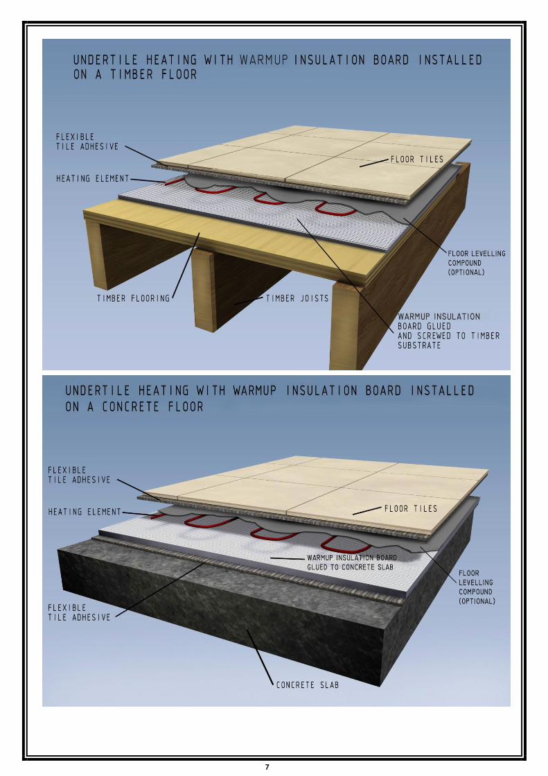
To fully utilise the long-term durability of your tiles, whether heated or not, it
is important that the design, construction and preparation of the subfloor is
carried out correctly.
It is essential that the subfloor be sufficiently rigid to support the ultimate
weight that it will have to bear without movement or deflection. Wherever a
timber subfloor is to be heated and tiled, it is strongly recommended that a
Warmup insulation board be used as tile backer board prior to heating and
tiling.
Waterproofing requirements will be determined based on installation methods
and local regulatory requirements.
The installations should comply with the following Codes of Practice:
BRANZ – Good Tiling Practice
NZ Electrical Installation NZS 3000:2007
NZS 3100-2009
NZS 6110:2007
The choice of products for subfloor preparation and tile fixing will vary
depending on the existing subfloor, preferred tiling system and choice of tile.
This document is only intended to be an outline guide to laying ceramic floor
tiles. Further help regarding floor preparation and tile application is available
from the tile adhesive manufacturers.
Technical notes
5

Ensure adequate underfloor ventilation.
Securely fix existing floor boards and if necessary, pre-level with a latex/cement
self-levelling compound to give a flush fit for the subsequently applied tile
backer boards.
Using Warmup Insulation board
Fix the tile backer board as per manufacturer’s instructions.
After attaching the board to the subfloor, the Warmup Undertile heating system
may be laid directly on top of the tile backer/building board, and then tiled
over. It is important to ensure that the tile adhesive and grout used are flexible
and that the tile backer/building board has been fitted as per the
manufacturer’s instructions. High quality, cement-based adhesives with their
flexible additives are most suitable.
Preparation of timber or concrete subfloor
6
7
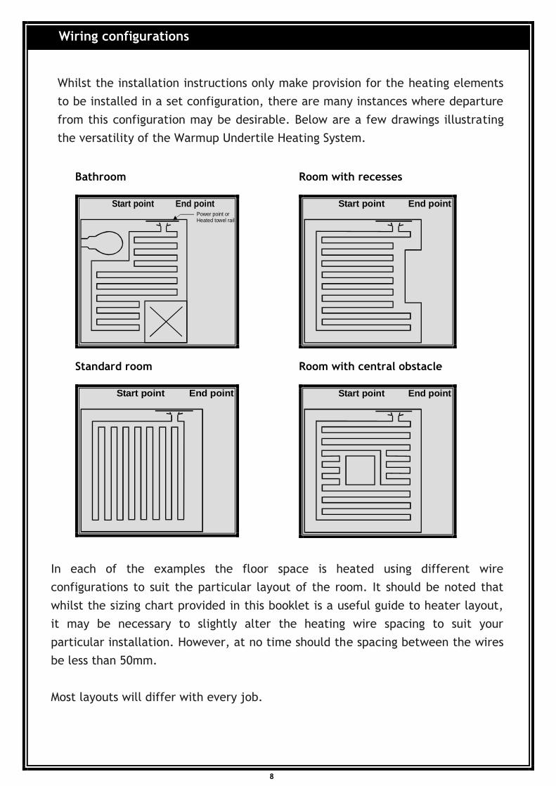
Whilst the installation instructions only make provision for the heating elements
to be installed in a set configuration, there are many instances where departure
from this configuration may be desirable. Below are a few drawings illustrating
the versatility of the Warmup Undertile Heating System.
In each of the examples the floor space is heated using different wire
configurations to suit the particular layout of the room. It should be noted that
whilst the sizing chart provided in this booklet is a useful guide to heater layout,
it may be necessary to slightly alter the heating wire spacing to suit your
particular installation. However, at no time should the spacing between the wires
be less than 50mm.
Most layouts will differ with every job.
Bathroom
Power point orHeated towel rail
Start point End point
Room with recesses
Start point End point
Standard room
Start point End point
Room with central obstacle
Start point End point
Wiring configurations
8

Cross section for pre-wire requirements of undertile and undercarpet heating systems
The heating elements must be protected by an RCD with a rated residual
operating current not exceeding 30mA. The electrician must install a dedicated
RCD or use an existing RCD.
The flush box may need to be checked depending on the controller selected
Notes:
1. All our controllers are designed to fit Vertical flush boxes.
2. Height off the floor for flush boxes can vary with controllers.
3. The use of 2.5mm TPS as a draw wire is preferred. Ensure that it has a clear
passage from floor to flush box.
4. Kindly contact us on 0800 WARMUP(927-687) for any queries on pre-wire
connections.
Electrical requirements
9
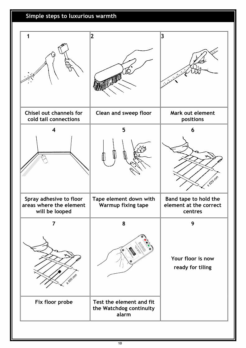
1 2 3
Chisel out channels for cold tail connections
Clean and sweep floor Mark out element positions
4 5 6
Spray adhesive to floor areas where the element
will be looped
Tape element down with Warmup fixing tape
Band tape to hold the element at the correct
centres
7 8 9
Your floor is now
ready for tiling
Fix floor probe Test the element and fit the Watchdog continuity
alarm
Simple steps to luxurious warmth
10

Note
• Your Warmup Heating element has been classified as an electrical appliance.
• You are therefore not required to be an electrician to install the element. But
all electrical connections including the connection of the controller must be
undertaken by a licensed electrician.
• Ensure all electrical supply circuits to the heating elements are protected via
a RCD (Residual Current Device) protected circuit.
• Once the heater and controller have been installed and the tile adhesive has
cured, the heater can be switched on.
Initial heat up time will vary depending upon the age of the floor, floor type
(concrete or timber), time of year, thermal characteristics and insulation of your
sub floor. The heat up times will improve with increased usage. Ensure your
electrician reads the instructions supplied with the thermostat before connecting
it.
Simple steps to luxurious warmth
11

Chisel out channels for cold tails
Clean and sweep floor
1. Chisel out channels for cold tail connections
To ensure a flat floor surface, it will be necessary
to chisel out or “chase” short channels in the
subfloor at the “start point” and the “end point”.
This minimises the increased height presented by
the two black power supply cables. The start and
end points of the heating element should be at
least 50mm apart (no closer) maximum 100mm (see
sizing guide).
Never cross over any of the heating elements.
If the element is being fitted to a solid concrete
floor, it is essential that the concrete is fully cured
to the manufacturer’s specifications. Also be aware
that on a solid concrete foundation you may need
to fix the element runs closer than the average of
75mm, as the concrete will draw away much of the
heat and increasing the time it takes to heat up to
temperature.
The lowest ambient temperature at which the
heating element may be installed is 0deg and must
be installed at a distance of at least 30mm from
conductive parts of the building, such as water
pipes.
2 Clean and sweep floor
Ensure that the floor surface is smooth, dry and
free from dust or grease.
Installation Steps 1 & 2
12

Measure up
Mark start point
Mark corners and perimeter
Mark spacing intervals
Spray adhesive
Installation Steps 3 & 4
3. Mark the floor for element position
Calculate in square metres the actual area to be
heated. Then using a sizing guide, establish the
actual element spacings.
Using a fibre tipped pen mark a starting point no
further than 1.5m from the power supply. The
start point should be positioned as close as
possible to the power supply.
Mark all the outer corners of the heated area
observing the perimeter distances and join the
corners up to form a marked out perimeter.
Mark up the spacing intervals for the element wire
following the sizing guide plus your actual
calculation. The spacing interval between the
element wire must be at least 50mm apart. The
maximum spacing interval that is recommended is
100mm.
4. Spray adhesive to floor areas where the element
will be looped
Spray the floor with the adhesive spray along areas
where the cable loops around, or where the
element will require taping in place. The spray
adhesive acts as a primer for the tape and should
only be used where the element is to be taped to
the floor. Allow to cure for approximately 10
minutes.
13

Unroll the power supply cable from spool
Lay wire out around perimeter from start point
Lay out heating wire in parallel lines
Space and secure wire with tape
Installation Steps 5 & 6
5. Tape the heating element down with Warmup
fixing tape
Once the floor has been marked up, the element
wire can be laid out.
Gently unroll the power supply cable from the
spool. After 3 metres of black cable has been
removed, you will reach the point at which the
power supply cable joins the heating element
wire (which is of a different colour).
The join of the power supply cable and the
heating cable should be taped to the floor at the
start point (which is the first of the chiselled
channels).
Following the perimeter markings on the floor,
lay out the heating element wire, taping down at
each corner. The element wire should run from
the start point in a U shape to the furthest
corner from the start point.
Once the element wire has been laid out around
the perimeter, start laying out the heater wire in
parallel lines back and forth across the main body
of the area to be heated.
Using the spacing markings, tape down the
element to the floor with strips of the adhesive
tape supplied (over the pre sprayed areas). The
tape strips should be about 25mm (1 inch) long.
You will also note a ½ way marker indicating that
you have used up ½ the length of the heating
element. Check the coverage of the floor already
completed to gauge your end result.
14

Tape down end point join parallel with start point
Lay out balance of wire
Adjust wire spacing if necessary
Secure the wire with tape and band the tape to hold the element in place
When you have completed about 90% of the
element layout, gently unroll the remaining wire
and the second power supply cable (black) from
the spool. At the end point where the power
supply cable meets the heating element you will
find another join. Tape this join to the end point
(which is the second chiselled channel), at least
50mm apart from the start point join that you
taped down previously.
You will be left with a coil of unsecured element.
This unsecured element should be laid out in
reverse order i.e. starting from the end point and
working backwards to the last point at which the
element was taped down.
In order to achieve even coverage of the balance
of the area to be heated, you may at this stage
need to adjust some of the element spacing that
you previously secured.
This can be achieved by untaping a few of the
previous runs of element that you taped down,
and re-fixing them at wider or narrower intervals.
You may wish to alter the element layout to fit
your particular requirements. Where there are
irregularities of shape you can lay out the element
to provide warmth around toilets, etc. This is
quite acceptable provided that:
a. The element is spaced at least 50mm apart at
all times. Not closer.
b. The element should never cross over.
c. The heating part of the element is never
within the wall cavity.
Once the laying of the element is complete,
meaning the black leads are both back to the
starting point, these will need to be carefully
pulled up within the wall cavity using the draw
wire.
6. Band the tape to hold the element
Once the heating element is completely laid out,
spray adhesive across the element at right angles
to the wire and band Warmup fixing tape to hold
the element at the correct centres.
15
Installation Steps 5 & 6

Fix floor probe
7. Fix floor probe
One of the final steps is to fit the floor probe.
The probe goes up through the wall cavity with
the power supply cables, therefore you need to
make sure there is enough wire from the probe
to go up to where the controller is to be fitted.
Secure the additional wire from the probe by
running it along the floor and up in between
two rows of heating element and tape on the
floor as far as you can. The closer to the centre
of the floor you can get is the best option but it
must not cross over any other wires on the
floor.
Now the laying of the floor is complete, the two
power supply cables and the probe wire will
need to be very carefully pulled up through the
wall cavity using the draw wire.
Installation Step 7
16

Check resistance using a multi-meter
Check and test the Watchdog continuity alarm
8. Testing the heater (Prior to and during
tiling/tiling procedures)
Your Warmup undertile heater has been
comprehensively tested prior to sale. You should
retest the heater by using the following method
Check the resistance on the heater, using a multi
meter and confirm the reading against factory
specifications (label on the cardboard spool).
Test the heating element using an insulation tester
(min. voltage 500V).
Connect the Watchdog continuity alarm (supplied
with each heating element). Follow the connection
instructions.
If the alarm sounds during the tiling procedure,
stop all work and call for technical assistance on
0800 WARMUP (927-687).
After the tiling and grouting procedure has been
completed, the checks 1 and 2 need to be
repeated.
The electrician needs to complete the test report
label as provided and attach to either the cold
tails or switchboard.
9. Connection and testing of the Watchdog
Continuity alarm
Ensure that the batteries are correctly installed.
Test by turning the switch to the ON position and
ensure that the audible alarm sounds. If the alarm
sound cannot be heard, please call for technical
assistance on 0800 WARMUP (927-687).
Turn to the OFF position during connection to the
heating element and then turn it ON.
Note: When the heating element is connected to
the Watchdog continuity alarm and turned on,
there should be no alarm sound audible. Your
floor is now ready for tiling
Installation Steps 8 & 9
17
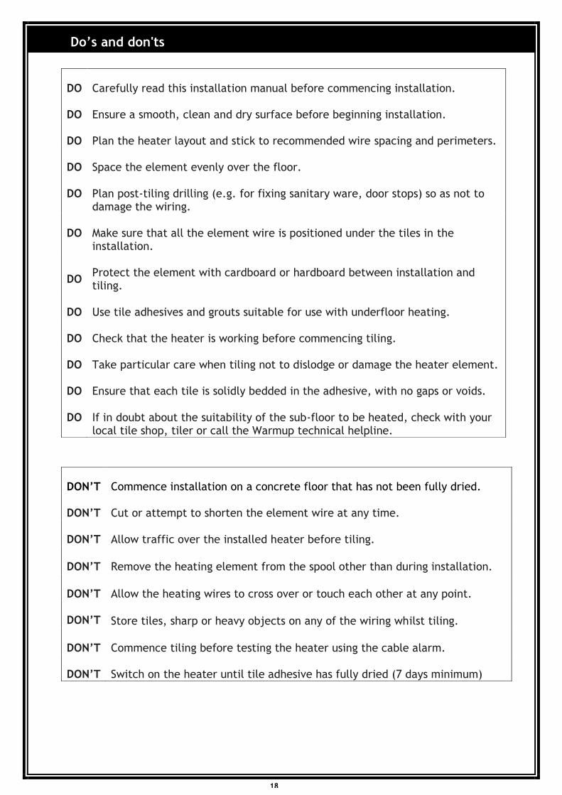
DO
DO
Carefully read this installation manual before commencing installation.
Ensure a smooth, clean and dry surface before beginning installation.
DO Plan the heater layout and stick to recommended wire spacing and perimeters.
DO Space the element evenly over the floor.
DO Plan post-tiling drilling (e.g. for fixing sanitary ware, door stops) so as not to damage the wiring.
DO Make sure that all the element wire is positioned under the tiles in the installation.
DO Protect the element with cardboard or hardboard between installation and tiling.
DO Use tile adhesives and grouts suitable for use with underfloor heating.
DO Check that the heater is working before commencing tiling.
DO Take particular care when tiling not to dislodge or damage the heater element.
DO Ensure that each tile is solidly bedded in the adhesive, with no gaps or voids.
DO If in doubt about the suitability of the sub-floor to be heated, check with your local tile shop, tiler or call the Warmup technical helpline.
DON’T Commence installation on a concrete floor that has not been fully dried.
DON’T Cut or attempt to shorten the element wire at any time.
DON’T Allow traffic over the installed heater before tiling.
DON’T Remove the heating element from the spool other than during installation.
DON’T Allow the heating wires to cross over or touch each other at any point.
DON’T Store tiles, sharp or heavy objects on any of the wiring whilst tiling.
DON’T Commence tiling before testing the heater using the cable alarm.
DON’T Switch on the heater until tile adhesive has fully dried (7 days minimum)
18
Do’s and don'ts

InstallationManual
(Undertile Heating Kit)
Technical Helpline
0800 927 687
IMPORTANTPlease read the ENTIRE Installation Manual before attempting to install your undertile heater.Incorrectinstallation could damage the cable and invalidate your warranty.
Warmup New Zealand LtdFreephone: 0800 927 687 Website: www.warmup.co.nz Email: [email protected]