installation manual - watts watermedia.wattswater.com/stennerfeedpump.pdf · faulty wiring, weather...
TRANSCRIPT

Classic SeriesINSTALLATION MANUAL
Metering PumpsManufactured Since 1957
www.stenner.com2
Table of Contents
Warranty and Service Policy . . . . . . . . . . . . . . . . . . . . . . . . . . . . . . . . . . . . . . . . 3
Safety Information . . . . . . . . . . . . . . . . . . . . . . . . . . . . . . . . . . . . . . . . . . . . . . . 4-5
Pump Identification . . . . . . . . . . . . . . . . . . . . . . . . . . . . . . . . . . . . . . . . . . . . . . 6-7
Outputs . . . . . . . . . . . . . . . . . . . . . . . . . . . . . . . . . . . . . . . . . . . . . . . . . . . . . . . 8-15
Materials of Construction . . . . . . . . . . . . . . . . . . . . . . . . . . . . . . . . . . . . . . . . . . 16
Accessory Checklist . . . . . . . . . . . . . . . . . . . . . . . . . . . . . . . . . . . . . . . . . . . . . . 17
Installation . . . . . . . . . . . . . . . . . . . . . . . . . . . . . . . . . . . . . . . . . . . . . . . . . . . . . 18-26
Troubleshooting . . . . . . . . . . . . . . . . . . . . . . . . . . . . . . . . . . . . . . . . . . . . . . . . . 27-30
Tube Replacement . . . . . . . . . . . . . . . . . . . . . . . . . . . . . . . . . . . . . . . . . . . . . . . 31-35
Motor – exploded view and parts . . . . . . . . . . . . . . . . . . . . . . . . . . . . . . . . . . . 36-38
Feed Rate Control – exploded view and parts . . . . . . . . . . . . . . . . . . . . . . . . . . 39-40
Pump Head – exploded view and parts . . . . . . . . . . . . . . . . . . . . . . . . . . . . . . . 41-44
Pump Tubes . . . . . . . . . . . . . . . . . . . . . . . . . . . . . . . . . . . . . . . . . . . . . . . . . . . . 45
Check Valves . . . . . . . . . . . . . . . . . . . . . . . . . . . . . . . . . . . . . . . . . . . . . . . . . . . 46
For Your Records . . . . . . . . . . . . . . . . . . . . . . . . . . . . . . . . . . . . . . . . . . . . . . . . 47
CIMM06
US and Canada call 1.800.683.2378, other countries call 1.904.641.1666 3
Damaged or Lost ShipmentsUPS and prepaid truck shipments: Check your orderimmediately upon arrival. All damage must be noted onthe delivery receipt. Call Stenner Customer Service at800.683.2378 for all shortages and damages withinseven (7) days of receipt.
ReturnsStenner offers a 30-day return policy on factory directpurchases. Except as otherwise provided, no materialwill be accepted for return after 30 days from purchase.To return merchandise at any time, call Stenner at800.683.2378 for a Returned Goods Authorization(RGA) number. A 15% re-stocking fee will be applied.Include a copy of your invoice or packing slip with yourreturn.
Limited WarrantyStenner Pump Company will for a period of one (1) yearfrom the date of purchase (proof of purchase required)repair or replace – at our option – all defective parts.Stenner Pump Company is not responsible for any
removal or installation costs. Pump tube assemblies andrubber components are considered perishable and arenot covered in this warranty. Pump tube will be replacedeach time a pump is in for service, unless otherwisespecified. The cost of the pump tube replacement willbe the responsibility of the customer. Stenner PumpCompany will incur shipping costs for warranty productsshipped from our factory in Jacksonville, Florida. Anytampering with major components, chemical damage,faulty wiring, weather conditions, water damage, powersurges, or products not used with reasonable care andmaintained in accordance with the instructions will voidthe warranty. Stenner Pump Company limits its liabilitysolely to the cost of the original product. We make noother warranty expressed or implied.
DisclaimerThe information contained in this manual is notintended for specific application purposes. StennerPump Company reserves the right to make changes toprices, products, and specifications at any time withoutprior notice.
Warranty and Service Policy

www.stenner.com4
Safety Information
ELECTRIC SHOCK HAZARD:Pump supplied with grounding power cord and attached plug. To reduce risk of electrical shock, connect only to a properlygrounded, grounding type receptacle.
RISQUE DE CHOC ELECTRIQUE:Cette pompe est équipée d’une fiche de mise à terre. Pour réduire le risque de choc électrique, s’assurer que la fiche est bien raccordée à une prise de courant avec une connexion de mise à terre.
DO NOT alter the power cord or plug end.
DO NOT use receptacle adapters.
DO NOT use pump with a damaged or altered power cord or plug. Contact the factory or an authorized service facilityfor repair.
HAZARDOUS VOLTAGE: DISCONNECT power cord before removing motor cover forservice. Electrical service by trained personnel only.
EXPLOSION HAZARD:This pump is not explosion proof. Do Not install or operate in an explosive environment.
RISK OF CHEMICAL EXPOSURE:Potential for chemical burns, fire, explosion, personal injury, orproperty damage. To reduce risk of exposure, the use of properpersonal protective equipment is mandatory.
RISK OF FIRE HAZARD: Do Not install or operate on any flammable surface.
RISK OF CHEMICAL OVERDOSE:To reduce risk, follow proper installation methods andrecommendations. Check your local codes for additionalguidelines.
AVERTISSEMENT
Warns about hazards that CAN causedeath, serious personal injury, or property damage if ignored.
ELECTRIC SHOCK HAZARD
US and Canada call 1.800.683.2378, other countries call 1.904.641.1666 5
Safety Information continued
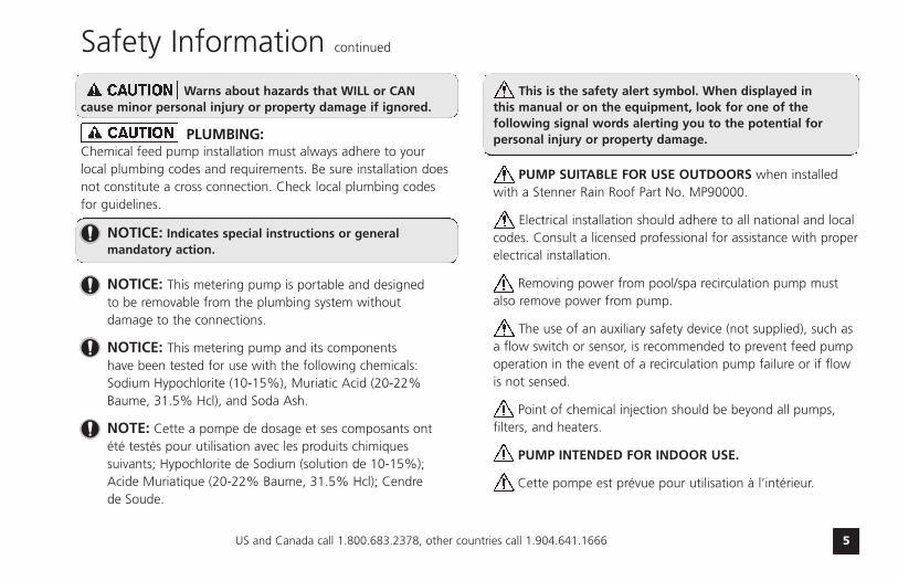
Warns about hazards that WILL or CAN cause minor personal injury or property damage if ignored.
PLUMBING:
NOTICE: Indicates special instructions or general mandatory action.
NOTICE: This metering pump is portable and designed to be removable from the plumbing system without damage to the connections.
NOTICE: This metering pump and its components have been tested for use with the following chemicals: Sodium Hypochlorite (10-15%), Muriatic Acid (20-22% Baume, 31.5% Hcl), and Soda Ash.
NOTE: Cette a pompe de dosage et ses composants ont été testés pour utilisation avec les produits chimiques suivants; Hypochlorite de Sodium (solution de 10-15%); Acide Muriatique (20-22% Baume, 31.5% Hcl); Cendrede Soude.
This is the safety alert symbol. When displayed in this manual or on the equipment, look for one of thefollowing signal words alerting you to the potential forpersonal injury or property damage.
PUMP SUITABLE FOR USE OUTDOORS when installedwith a Stenner Rain Roof Part No. MP90000.
Electrical installation should adhere to all national and localcodes. Consult a licensed professional for assistance with properelectrical installation.
Removing power from pool/spa recirculation pump mustalso remove power from pump.
The use of an auxiliary safety device (not supplied), such asa flow switch or sensor, is recommended to prevent feed pumpoperation in the event of a recirculation pump failure or if flowis not sensed.
Point of chemical injection should be beyond all pumps,filters, and heaters.
PUMP INTENDED FOR INDOOR USE.
Cette pompe est prévue pour utilisation à l’intérieur.
Chemical feed pump installation must always adhere to yourlocal plumbing codes and requirements. Be sure installation doesnot constitute a cross connection. Check local plumbing codesfor guidelines.
www.stenner.com6
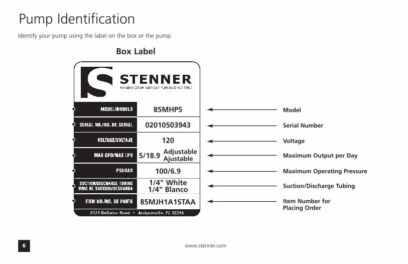
Pump Identification
Model
Serial Number
Maximum Output per Day
Suction/Discharge Tubing
Item Number forPlacing Order
Voltage
Identify your pump using the label on the box or the pump.
85MHP5
02010503943
120
5/18.9 Adjustable5/18.9 Ajustable
100/6.9
1/4" White1/4" Blanco
85MJH1A1STAA
Box Label
5/18.9
Maximum Operating Pressure
US and Canada call 1.800.683.2378, other countries call 1.904.641.1666 7
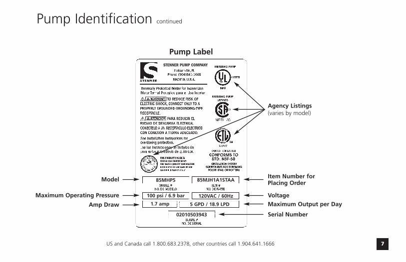
Pump Identification continued
Item Number forPlacing Order
Voltage
Maximum Output per Day
85MHP5 85MJH1A1STAA
100 psi / 6.9 bar 120VAC / 60Hz
1.7 amp 5 GPD / 18.9 LPD
02010503943
Pump Label
Model
Maximum Operating Pressure
Agency Listings(varies by model)
Serial Number
Amp Draw
STENNER PUMP COMPANY

www.stenner.com8
Outputs 45 series
Single Head Maximum Pump Tube gallons liters gallons liters ounces milliliters liters liters millilitersModel Pressure Number per day per day per hour per hour per minute per minute per day per hour per minute
Adjustable45MHP2* 100 psi/6.9 bar #1 0.2 to 3.0 0.8 to 11.4 0.01 to 0.13 0.03 to 0.48 0.02 to 0.27 0.56 to 7.92 0.6 to 9.1 0.03 to 0.38 0.31 to 6.32
45M1 25 psi/1.7 bar #1Fixed Output45MPHP2* 100 psi/6.9 bar #1 3.0 11.4 0.13 0.48 0.27 7.92 9.1 0.38 6.32
45MP1 25 psi/1.7 bar #1
Adjustable45MHP10* 100 psi/6.9 bar #2 0.5 to 10.0 1.9 to 37.9 0.02 to 0.42 0.08 to 1.58 0.04 to 0.89 1.32 to 26.32 1.5 to 30.3 0.06 to 1.26 1.04 to 21.04
45M2 25 psi/1.7 bar #2Fixed Output45MPHP10* 100 psi/6.9 bar #2 10.0 37.9 0.42 1.58 0.89 26.32 30.3 1.26 21.04
45MP2 25 psi/1.7 bar #2
Adjustable45MHP22* 100 psi/6.9 bar #7 1.1 to 22.0 4.2 to 83.3 0.05 to 0.92 0.18 to 3.47 0.10 to 1.96 2.92 to 57.85 3.3 to 66.6 0.14 to 2.78 2.29 to 46.25
45M3 25 psi/1.7 bar #3Fixed Output45MPHP22* 100 psi/6.9 bar #7 22.0 83.3 0.92 3.47 1.96 57.85 66.6 2.78 46.25
45MP3 25 psi/1.7 bar #3
Adjustable45M4 25 psi/1.7 bar #4 1.7 to 35.0 6.4 to 132.5 0.07 to 1.46 0.27 to 5.52 0.15 to 3.11 4.44 to 92.01 5.1 to 106.0 0.21 to 4.42 3.54 to 73.61
Fixed Output45MP4 25 psi/1.7 bar #4 35.0 132.5 1.46 5.52 3.11 92.01 106.0 4.42 73.61
Adjustable45M5 25 psi/1.7 bar #5 2.5 to 50.0 9.5 to 189.3 0.10 to 2.08 0.40 to 7.89 0.22 to 4.44 6.60 to 131.46 7.6 to 151.4 0.32 to 6.31 5.28 to 105.14
Fixed Output45MP5 25 psi/1.7 bar #5 50.0 189.3 2.08 7.89 4.44 131.43 151.4 6.31 105.14
Approx. Outputs @ 60 Hz Approx. Outputs @ 50 Hz
NOTICE: The information within this chart is solely intended for use as a guide. The output data is an approximation based on pumping water under a controlled testing environment. Many variables can affect the output of the pump. Stenner Pump Company recommends that all metering pumps undergo field calibration by means of analytical testing to confirm their outputs.
*pump supplied with injection check valve for 26-100 psi applications
The dial ring for adjustable pumps is marked L-10; L=5%, 1-10 indicates10% increments of maximum output. (20:1 Turndown Ratio)
0.2 to 3.0 0.8 to 11.4 0.01 to 0.13 0.03 to 0.48 0.02 to 0.27 0.56 to 7.92 0.6 to 9.1 0.03 to 0.38 0.31 to 6.32
3.0 11.4 0.13 0.48 0.27 7.92 9.1 0.38 6.32
0.5 to 10.0 1.9 to 37.9 0.02 to 0.42 0.08 to 1.58 0.04 to 0.89 1.32 to 26.32 1.5 to 30.3 0.06 to 1.26 1.04 to 21.04
10.0 37.9 0.42 1.58 0.89 26.32 30.3 1.26 21.04
1.1 to 22.0 4.2 to 83.3 0.05 to 0.92 0.18 to 3.47 0.10 to 1.96 2.92 to 57.85 3.3 to 66.6 0.14 to 2.78 2.29 to 46.25
22.0 83.3 0.92 3.47 1.96 57.85 66.6 2.78 46.25
US and Canada call 1.800.683.2378, other countries call 1.904.641.1666 9
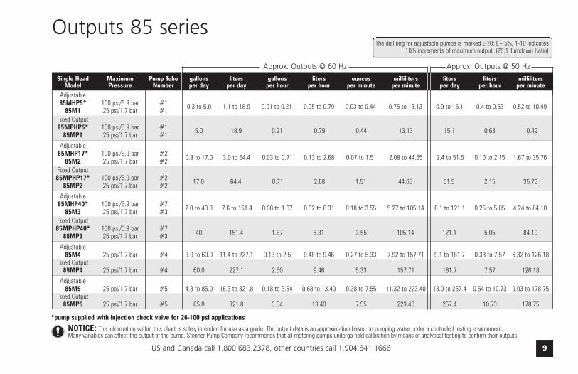
Single Head Maximum Pump Tube gallons liters gallons liters ounces milliliters liters liters millilitersModel Pressure Number per day per day per hour per hour per minute per minute per day per hour per minute
Adjustable85MHP5* 100 psi/6.9 bar #1 0.3 to 5.0 1.1 to 18.9 0.01 to 0.21 0.05 to 0.79 0.03 to 0.44 0.76 to 13.13 0.9 to 15.1 0.4 to 0.63 0.52 to 10.49
85M1 25 psi/1.7 bar #1Fixed Output85MPHP5* 100 psi/6.9 bar #1 5.0 18.9 0.21 0.79 0.44 13.13 15.1 0.63 10.49
85MP1 25 psi/1.7 bar #1
Adjustable85MHP17* 100 psi/6.9 bar #2 0.8 to 17.0 3.0 to 64.4 0.03 to 0.71 0.13 to 2.68 0.07 to 1.51 2.08 to 44.65 2.4 to 51.5 0.10 to 2.15 1.67 to 35.76
85M2 25 psi/1.7 bar #2Fixed Output85MPHP17* 100 psi/6.9 bar #2 17.0 64.4 0.71 2.68 1.51 44.65 51.5 2.15 35.76
85MP2 25 psi/1.7 bar #2
Adjustable85MHP40* 100 psi/6.9 bar #7 2.0 to 40.0 7.6 to 151.4 0.08 to 1.67 0.32 to 6.31 0.18 to 3.55 5.27 to 105.14 6.1 to 121.1 0.25 to 5.05 4.24 to 84.10
85M3 25 psi/1.7 bar #3Fixed Output85MPHP40* 100 psi/6.9 bar #7 40 151.4 1.67 6.31 3.55 105.14 121.1 5.05 84.10
85MP3 25 psi/1.7 bar #3
Adjustable85M4 25 psi/1.7 bar #4 3.0 to 60.0 11.4 to 227.1 0.13 to 2.5 0.48 to 9.46 0.27 to 5.33 7.92 to 157.71 9.1 to 181.7 0.38 to 7.57 6.32 to 126.18
Fixed Output85MP4 25 psi/1.7 bar #4 60.0 227.1 2.50 9.46 5.33 157.71 181.7 7.57 126.18
Adjustable85M5 25 psi/1.7 bar #5 4.3 to 85.0 16.3 to 321.8 0.18 to 3.54 0.68 to 13.40 0.38 to 7.55 11.32 to 223.40 13.0 to 257.4 0.54 to 10.73 9.03 to 178.75
Fixed Output85MP5 25 psi/1.7 bar #5 85.0 321.8 3.54 13.40 7.55 223.40 257.4 10.73 178.75
Approx. Outputs @ 60 Hz Approx. Outputs @ 50 Hz
Outputs 85 series
NOTICE: The information within this chart is solely intended for use as a guide. The output data is an approximation based on pumping water under a controlled testing environment. Many variables can affect the output of the pump. Stenner Pump Company recommends that all metering pumps undergo field calibration by means of analytical testing to confirm their outputs.
*pump supplied with injection check valve for 26-100 psi applications
The dial ring for adjustable pumps is marked L-10; L=5%, 1-10 indicates10% increments of maximum output. (20:1 Turndown Ratio)
0.3 to 5.0 1.1 to 18.9 0.01 to 0.21 0.05 to 0.79 0.03 to 0.44 0.76 to 13.13 0.9 to 15.1 0.4 to 0.63 0.52 to 10.49
5.0 18.9 0.21 0.79 0.44 13.13 15.1 0.63 10.49
0.8 to 17.0 3.0 to 64.4 0.03 to 0.71 0.13 to 2.68 0.07 to 1.51 2.08 to 44.65 2.4 to 51.5 0.10 to 2.15 1.67 to 35.76
17.0 64.4 0.71 2.68 1.51 44.65 51.5 2.15 35.76
2.0 to 40.0 7.6 to 151.4 0.08 to 1.67 0.32 to 6.31 0.18 to 3.55 5.27 to 105.14 6.1 to 121.1 0.25 to 5.05 4.24 to 84.10
40 151.4 1.67 6.31 3.55 105.14 121.1 5.05 84.10
www.stenner.com10
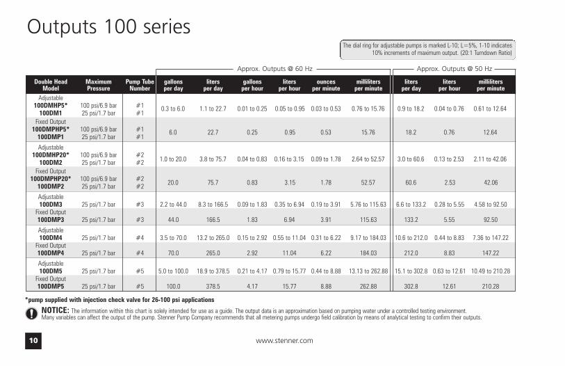
Double Head Maximum Pump Tube gallons liters gallons liters ounces milliliters liters liters millilitersModel Pressure Number per day per day per hour per hour per minute per minute per day per hour per minute
Adjustable100DMHP5* 100 psi/6.9 bar #1 0.3 to 6.0 1.1 to 22.7 0.01 to 0.25 0.05 to 0.95 0.03 to 0.53 0.76 to 15.76 0.9 to 18.2 0.04 to 0.76 0.61 to 12.64
100DM1 25 psi/1.7 bar #1Fixed Output
100DMPHP5* 100 psi/6.9 bar #1 6.0 22.7 0.25 0.95 0.53 15.76 18.2 0.76 12.64100DMP1 25 psi/1.7 bar #1
Adjustable100DMHP20* 100 psi/6.9 bar #2 1.0 to 20.0 3.8 to 75.7 0.04 to 0.83 0.16 to 3.15 0.09 to 1.78 2.64 to 52.57 3.0 to 60.6 0.13 to 2.53 2.11 to 42.06
100DM2 25 psi/1.7 bar #2Fixed Output
100DMPHP20* 100 psi/6.9 bar #2 20.0 75.7 0.83 3.15 1.78 52.57 60.6 2.53 42.06100DMP2 25 psi/1.7 bar #2
Adjustable100DM3 25 psi/1.7 bar #3 2.2 to 44.0 8.3 to 166.5 0.09 to 1.83 0.35 to 6.94 0.19 to 3.91 5.76 to 115.63 6.6 to 133.2 0.28 to 5.55 4.58 to 92.50
Fixed Output100DMP3 25 psi/1.7 bar #3 44.0 166.5 1.83 6.94 3.91 115.63 133.2 5.55 92.50
Adjustable100DM4 25 psi/1.7 bar #4 3.5 to 70.0 13.2 to 265.0 0.15 to 2.92 0.55 to 11.04 0.31 to 6.22 9.17 to 184.03 10.6 to 212.0 0.44 to 8.83 7.36 to 147.22
Fixed Output100DMP4 25 psi/1.7 bar #4 70.0 265.0 2.92 11.04 6.22 184.03 212.0 8.83 147.22
Adjustable100DM5 25 psi/1.7 bar #5 5.0 to 100.0 18.9 to 378.5 0.21 to 4.17 0.79 to 15.77 0.44 to 8.88 13.13 to 262.88 15.1 to 302.8 0.63 to 12.61 10.49 to 210.28
Fixed Output100DMP5 25 psi/1.7 bar #5 100.0 378.5 4.17 15.77 8.88 262.88 302.8 12.61 210.28
Approx. Outputs @ 60 Hz Approx. Outputs @ 50 Hz
Outputs 100 series
NOTICE: The information within this chart is solely intended for use as a guide. The output data is an approximation based on pumping water under a controlled testing environment. Many variables can affect the output of the pump. Stenner Pump Company recommends that all metering pumps undergo field calibration by means of analytical testing to confirm their outputs.
*pump supplied with injection check valve for 26-100 psi applications
The dial ring for adjustable pumps is marked L-10; L=5%, 1-10 indicates10% increments of maximum output. (20:1 Turndown Ratio)
0.3 to 6.0 1.1 to 22.7 0.01 to 0.25 0.05 to 0.95 0.03 to 0.53 0.76 to 15.76 0.9 to 18.2 0.04 to 0.76 0.61 to 12.64
6.0 22.7 0.25 0.95 0.53 15.76 18.2 0.76 12.64
1.0 to 20.0 3.8 to 75.7 0.04 to 0.83 0.16 to 3.15 0.09 to 1.78 2.64 to 52.57 3.0 to 60.6 0.13 to 2.53 2.11 to 42.06
20.0 75.7 0.83 3.15 1.78 52.57 60.6 2.53 42.06
US and Canada call 1.800.683.2378, other countries call 1.904.641.1666 11
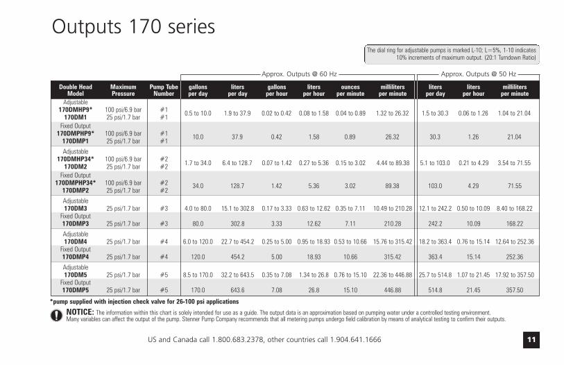
Double Head Maximum Pump Tube gallons liters gallons liters ounces milliliters liters liters millilitersModel Pressure Number per day per day per hour per hour per minute per minute per day per hour per minute
Adjustable170DMHP9* 100 psi/6.9 bar #1 0.5 to 10.0 1.9 to 37.9 0.02 to 0.42 0.08 to 1.58 0.04 to 0.89 1.32 to 26.32 1.5 to 30.3 0.06 to 1.26 1.04 to 21.04
170DM1 25 psi/1.7 bar #1Fixed Output
170DMPHP9* 100 psi/6.9 bar #1 10.0 37.9 0.42 1.58 0.89 26.32 30.3 1.26 21.04170DMP1 25 psi/1.7 bar #1
Adjustable170DMHP34* 100 psi/6.9 bar #2 1.7 to 34.0 6.4 to 128.7 0.07 to 1.42 0.27 to 5.36 0.15 to 3.02 4.44 to 89.38 5.1 to 103.0 0.21 to 4.29 3.54 to 71.55
170DM2 25 psi/1.7 bar #2Fixed Output
170DMPHP34* 100 psi/6.9 bar #2 34.0 128.7 1.42 5.36 3.02 89.38 103.0 4.29 71.55170DMP2 25 psi/1.7 bar #2
Adjustable170DM3 25 psi/1.7 bar #3 4.0 to 80.0 15.1 to 302.8 0.17 to 3.33 0.63 to 12.62 0.35 to 7.11 10.49 to 210.28 12.1 to 242.2 0.50 to 10.09 8.40 to 168.22
Fixed Output170DMP3 25 psi/1.7 bar #3 80.0 302.8 3.33 12.62 7.11 210.28 242.2 10.09 168.22
Adjustable170DM4 25 psi/1.7 bar #4 6.0 to 120.0 22.7 to 454.2 0.25 to 5.00 0.95 to 18.93 0.53 to 10.66 15.76 to 315.42 18.2 to 363.4 0.76 to 15.14 12.64 to 252.36
Fixed Output170DMP4 25 psi/1.7 bar #4 120.0 454.2 5.00 18.93 10.66 315.42 363.4 15.14 252.36
Adjustable170DM5 25 psi/1.7 bar #5 8.5 to 170.0 32.2 to 643.5 0.35 to 7.08 1.34 to 26.8 0.76 to 15.10 22.36 to 446.88 25.7 to 514.8 1.07 to 21.45 17.92 to 357.50
Fixed Output170DMP5 25 psi/1.7 bar #5 170.0 643.6 7.08 26.8 15.10 446.88 514.8 21.45 357.50
Approx. Outputs @ 60 Hz Approx. Outputs @ 50 Hz
Outputs 170 series
NOTICE: The information within this chart is solely intended for use as a guide. The output data is an approximation based on pumping water under a controlled testing environment. Many variables can affect the output of the pump. Stenner Pump Company recommends that all metering pumps undergo field calibration by means of analytical testing to confirm their outputs.
*pump supplied with injection check valve for 26-100 psi applications
The dial ring for adjustable pumps is marked L-10; L=5%, 1-10 indicates10% increments of maximum output. (20:1 Turndown Ratio)
0.5 to 10.0 1.9 to 37.9 0.02 to 0.42 0.08 to 1.58 0.04 to 0.89 1.32 to 26.32 1.5 to 30.3 0.06 to 1.26 1.04 to 21.04
10.0 37.9 0.42 1.58 0.89 26.32 30.3 1.26 21.04
1.7 to 34.0 6.4 to 128.7 0.07 to 1.42 0.27 to 5.36 0.15 to 3.02 4.44 to 89.38 5.1 to 103.0 0.21 to 4.29 3.54 to 71.55
34.0 128.7 1.42 5.36 3.02 89.38 103.0 4.29 71.55
www.stenner.com12
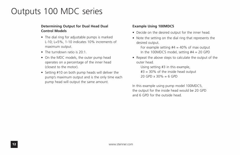
Outputs 100 MDC series
Determining Output for Dual Head Dual Control Models
• The dial ring for adjustable pumps is marked L-10; L=5%, 1-10 indicates 10% increments ofmaximum output.
• The turndown ratio is 20:1.
• On the MDC models, the outer pump head operates on a percentage of the inner head (closest to the motor).
• Setting #10 on both pump heads will deliver thepump’s maximum output and is the only time eachpump head will output the same amount.
Example Using 100MDC5
• Decide on the desired output for the inner head.
• Note the setting on the dial ring that represents thedesired output.
For example setting #4 = 40% of max outputIn the 100MDC5 model, setting #4 = 20 GPD
• Repeat the above steps to calculate the output of theouter head.
Using setting #3 in this example, #3 = 30% of the inside head output 20 GPD x 30% = 6 GPD
In this example using pump model 100MDC5, the output for the inside head would be 20 GPD and 6 GPD for the outside head.

US and Canada call 1.800.683.2378, other countries call 1.904.641.1666 13
Outputs 100 MDC series
Dual Head Maximum Pump Tube gallons liters gallons liters ounces milliliters liters liters millilitersDual Control Pressure Number per day per day per hour per hour per minute per minute per day per hour per minute
ModelAdjustable
100MDCHP5* 100 psi/6.9 bar #1 0.2 to 3.0 0.8 to 11.4 0.01 to 0.13 0.03 to 0.48 0.02 to 0.27 0.56 to 7.92 0.6 to 9.1 0.03 to 0.38 0.42 to 6.32100MDC1 25 psi/1.7 bar #1
100MDCHP20* 100 psi/6.9 bar #2 0.5 to 10.0 1.9 to 37.9 0.02 to 0.42 0.08 to 1.58 0.04 to 0.89 1.32 to 26.32 1.5 to 30.3 0.06 to 1.26 1.04 to 21.04100MDC2 25 psi/1.7 bar #2
100MDC3 25 psi/1.7 bar #3 1.1 to 22.0 4.2 to 83.3 0.05 to 0.92 0.18 to 3.47 0.10 to 1.96 2.92 to 57.85 3.3 to 66.6 0.14 to 2.78 2.29 to 46.25
100MDC4 25 psi/1.7 bar #4 1.7 to 35.0 6.4 to 132.5 0.07 to 1.46 0.27 to 5.52 0.15 to 3.11 4.44 to 92.01 5.1 to 106.0 0.21 to 4.42 3.54 to 73.61
100MDC5 25 psi/1.7 bar #5 2.5 to 50.0 9.5 to 189.3 0.10 to 2.08 0.40 to 7.89 0.22 to 4.44 6.60 to 131.46 7.6 to 151.4 0.32 to 6.31 5.28 to 105.14
Outputs for Inner Pump Head OnlyApprox. Outputs @ 60 Hz Approx. Outputs @ 50 Hz
NOTICE: The information within this chart is solely intended for use as a guide. The output data is an approximation based on pumping water under a controlled testing environment. Many variables can affect the output of the pump. Stenner Pump Company recommends that all metering pumps undergo field calibration by means of analytical testing to confirm their outputs.
*pump supplied with injection check valve for 26-100 psi applications
The dial ring for adjustable pumps is marked L-10; L=5%, 1-10 indicates10% increments of maximum output. (20:1 Turndown Ratio)
0.2 to 3.0 0.8 to 11.4 0.01 to 0.13 0.03 to 0.48 0.02 to 0.27 0.56 to 7.92 0.6 to 9.1 0.03 to 0.38 0.42 to 6.32
0.5 to 10.0 1.9 to 37.9 0.02 to 0.42 0.08 to 1.58 0.04 to 0.89 1.32 to 26.32 1.5 to 30.3 0.06 to 1.26 1.04 to 21.04
www.stenner.com14
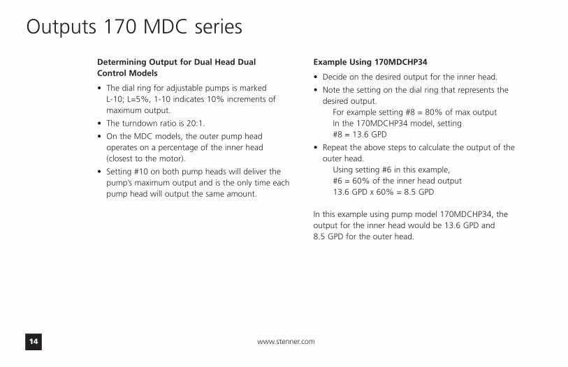
Outputs 170 MDC series
Determining Output for Dual Head Dual Control Models
• The dial ring for adjustable pumps is marked L-10; L=5%, 1-10 indicates 10% increments ofmaximum output.
• The turndown ratio is 20:1.
• On the MDC models, the outer pump head operates on a percentage of the inner head (closest to the motor).
• Setting #10 on both pump heads will deliver thepump’s maximum output and is the only time eachpump head will output the same amount.
Example Using 170MDCHP34
• Decide on the desired output for the inner head.
• Note the setting on the dial ring that represents thedesired output.
For example setting #8 = 80% of max outputIn the 170MDCHP34 model, setting #8 = 13.6 GPD
• Repeat the above steps to calculate the output of theouter head.
Using setting #6 in this example, #6 = 60% of the inner head output 13.6 GPD x 60% = 8.5 GPD
In this example using pump model 170MDCHP34, theoutput for the inner head would be 13.6 GPD and 8.5 GPD for the outer head.

US and Canada call 1.800.683.2378, other countries call 1.904.641.1666 15
Outputs 170 MDC series
Dual Head Maximum Pump Tube gallons liters gallons liters ounces milliliters liters liters millilitersDual Control Pressure Number per day per day per hour per hour per minute per minute per day per hour per minute
ModelAdjustable
170MDCHP9* 100 psi/6.9 bar #1 0.3 to 5.0 1.1 to 18.9 0.01 to 0.21 0.05 to 0.79 0.03 to 0.44 0.76 to 13.13 0.9 to 15.1 0.4 to 0.63 0.63 to 10.49170MDC1 25 psi/1.7 bar #1
170MDCHP34* 100 psi/6.9 bar #2 0.8 to 17.0 3.0 to 64.4 0.03 to 0.71 0.13 to 2.68 0.07 to 1.51 2.08 to 44.65 2.4 to 51.5 0.10 to 2.15 1.67 to 35.76170MDC2 25 psi/1.7 bar #2
170MDC3 25 psi/1.7 bar #3 2.0 to 40.0 7.6 to 151.4 0.08 to 1.67 0.32 to 6.31 0.18 to 3.55 5.27 to 105.14 6.1 to 121.1 0.25 to 5.05 4.24 to 84.10
170MDC4 25 psi/1.7 bar #4 3.0 to 60.0 11.4 to 227.1 0.13 to 2.5 0.48 to 9.46 0.27 to 5.33 7.92 to 157.71 9.1 to 181.7 0.38 to 7.57 6.32 to 126.18
170MDC5 25 psi/1.7 bar #5 4.3 to 85.0 16.3 to 321.8 0.18 to 3.54 0.68 to 13.40 0.38 to 7.55 11.32 to 223.40 13.0 to 257.4 0.54 to 10.73 9.03 to 178.75
Outputs for Inner Pump Head OnlyApprox. Outputs @ 60 Hz Approx. Outputs @ 50 Hz
NOTICE: The information within this chart is solely intended for use as a guide. The output data is an approximation based on pumping water under a controlled testing environment. Many variables can affect the output of the pump. Stenner Pump Company recommends that all metering pumps undergo field calibration by means of analytical testing to confirm their outputs.
*pump supplied with injection check valve for 26-100 psi applications
The dial ring for adjustable pumps is marked L-10; L=5%, 1-10 indicates10% increments of maximum output. (20:1 Turndown Ratio)
0.3 to 5.0 1.1 to 18.9 0.01 to 0.21 0.05 to 0.79 0.03 to 0.44 0.76 to 13.13 0.9 to 15.1 0.4 to 0.63 0.63 to 10.49
0.8 to 17.0 3.0 to 64.4 0.03 to 0.71 0.13 to 2.68 0.07 to 1.51 2.08 to 44.65 2.4 to 51.5 0.10 to 2.15 1.67 to 35.76
www.stenner.com16
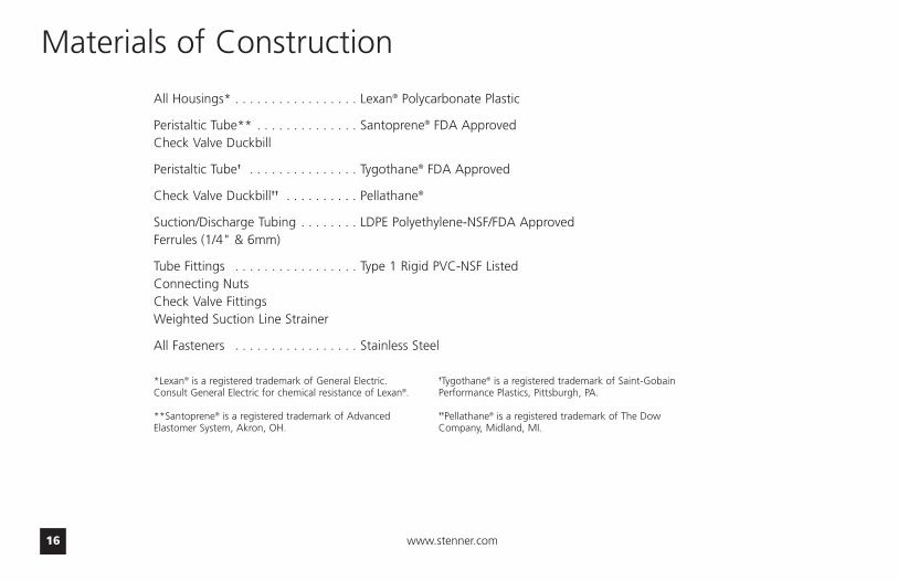
Materials of Construction
All Housings* . . . . . . . . . . . . . . . . . Lexan® Polycarbonate Plastic
Peristaltic Tube** . . . . . . . . . . . . . . Santoprene® FDA ApprovedCheck Valve Duckbill
Peristaltic Tube† . . . . . . . . . . . . . . . Tygothane® FDA Approved
Check Valve Duckbill†† . . . . . . . . . . Pellathane®
Suction/Discharge Tubing . . . . . . . . LDPE Polyethylene-NSF/FDA ApprovedFerrules (1/4" & 6mm)
Tube Fittings . . . . . . . . . . . . . . . . . Type 1 Rigid PVC-NSF ListedConnecting NutsCheck Valve FittingsWeighted Suction Line Strainer
All Fasteners . . . . . . . . . . . . . . . . . Stainless Steel
*Lexan® is a registered trademark of General Electric.Consult General Electric for chemical resistance of Lexan®.
**Santoprene® is a registered trademark of AdvancedElastomer System, Akron, OH.
†Tygothane® is a registered trademark of Saint-GobainPerformance Plastics, Pittsburgh, PA.
††Pellathane® is a registered trademark of The DowCompany, Midland, MI.
US and Canada call 1.800.683.2378, other countries call 1.904.641.1666 17
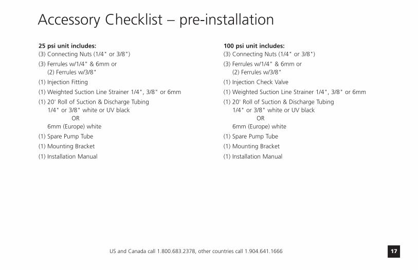
25 psi unit includes:(3) Connecting Nuts (1/4" or 3/8")
(3) Ferrules w/1/4" & 6mm or (2) Ferrules w/3/8"
(1) Injection Fitting
(1) Weighted Suction Line Strainer 1/4", 3/8" or 6mm
(1) 20' Roll of Suction & Discharge Tubing 1/4" or 3/8" white or UV black
OR 6mm (Europe) white
(1) Spare Pump Tube
(1) Mounting Bracket
(1) Installation Manual
100 psi unit includes:(3) Connecting Nuts (1/4" or 3/8")
(3) Ferrules w/1/4" & 6mm or (2) Ferrules w/3/8"
(1) Injection Check Valve
(1) Weighted Suction Line Strainer 1/4", 3/8" or 6mm
(1) 20' Roll of Suction & Discharge Tubing 1/4" or 3/8" white or UV black
OR 6mm (Europe) white
(1) Spare Pump Tube
(1) Mounting Bracket
(1) Installation Manual
Accessory Checklist – pre-installation
www.stenner.com18
Installation – additional safety instructions
Read all safety hazards before installing orservicing the pump. The pump is designedfor installation and service by properlytrained personnel.
Use all required personal protectiveequipment when working on or near a chemical metering pump.
Install the pump so that it is in compliancewith all national and local plumbing andelectrical codes.
Use the proper product to treatpotable water systems, use onlychemicals listed or approved for use.
Install the pump to work inconjunction with pool, spa, well pump, or system controls.
NOTICE: Indicates special instructions or general mandatory action.
US and Canada call 1.800.683.2378, other countries call 1.904.641.1666 19
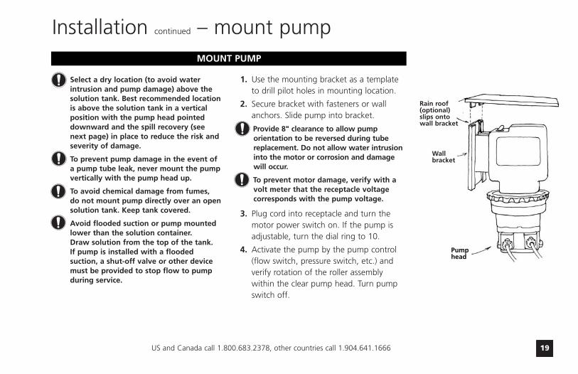
Select a dry location (to avoid waterintrusion and pump damage) above thesolution tank. Best recommended locationis above the solution tank in a verticalposition with the pump head pointeddownward and the spill recovery (seenext page) in place to reduce the risk andseverity of damage.
To prevent pump damage in the event ofa pump tube leak, never mount the pumpvertically with the pump head up.
To avoid chemical damage from fumes, do not mount pump directly over an opensolution tank. Keep tank covered.
Avoid flooded suction or pump mountedlower than the solution container. Draw solution from the top of the tank. If pump is installed with a floodedsuction, a shut-off valve or other devicemust be provided to stop flow to pumpduring service.
1. Use the mounting bracket as a template to drill pilot holes in mounting location.
2. Secure bracket with fasteners or wall anchors. Slide pump into bracket.
Provide 8" clearance to allow pumporientation to be reversed during tubereplacement. Do not allow water intrusioninto the motor or corrosion and damage will occur.
To prevent motor damage, verify with a volt meter that the receptacle voltage corresponds with the pump voltage.
3. Plug cord into receptacle and turn the motor power switch on. If the pump is adjustable, turn the dial ring to 10.
4. Activate the pump by the pump control (flow switch, pressure switch, etc.) and verify rotation of the roller assembly within the clear pump head. Turn pump switch off.
Installation continued – mount pump
Wallbracket
Rain roof(optional)slips ontowall bracket
Pumphead
MOUNT PUMP
www.stenner.com20
Installation continued – additional instructions for CE pumpsIstruzioni
Supplementari Per L’ installazione
1. Tutte le pompe Classe IIlocalizzate nella Zona 1della superficiecircostante la piscinadevono essere collocatedove gli allagamenti nopossono accadere.
2. Questa pompa, é inteso,deve essere installatacome ‘fissa’ e non comeportatile.
3. La tettoia deve essereinstallata e il montaggio‘orientazione verticale’dell’intera unitá deve essere osservato.
4. Dopo l’installazione, laspina deve essereaccessibile durante l’uso.
5. Questa unitá deve esseregettata via se il filoelettrico é danneggiato.
6. Osservare e aderire atutte le Norme NazionaliSugli Impianti Elettrici.
InstuccionesAdicionales Para
instalación
1. Todas las bombas Clase IIsituadas en la Zona 1 delas áreas de la piscinarequieren colocarsedonde no puedan serinundadas.
2. Esta bomba es para serinstalada “fija” en vez de portátil.
3. Es necesario instalar eltecho de lluvia, y montarla unidad enterasiguiendo una orintaciónvertical.
4. Depués de la instalaciónel enchufe suministradorde energia debe estaraccesible durante el uso.
5. Se deberá desechar launidad si el cordón deabastecimiento sedeteriora.
6. Observe y cumpla contodas las ReglasNacionales paraInstalaciones Eléctricas.
InstructionsSupplémentaires
d’Installtion
1. Toutes les pompesinstallées dans la Zone 1du périmètre de lapiscine doivent êtresituées de manière à nepas pouvoir êtreinondées.
2. Cette pompe est prévuepour installation fixe etnon pas portative.
3. L’abri anti-pluie doit êtreinstallé et l’orientationverticale doit toujoursêtre observée.
4. Après l’installation, laprise électrique doitrester accessible pendantl’utilisation.
5. Cette unité doit être miseau rebut si le cordonélectrique estendommagé.
6. Observez et adhérez àtoutes les NormesNationales pourInstallations Electriques.
ZustazlicheInstallierungsanweisung
un
1. Pumpen die sich in Zone 1vom Schwimmbeckenbefinden sollen sind soeinzurichten daßUeberschwemmungennicht vorkommen werden.
2. Diese Pumpe ist als festmontierte Ausrustungbedacht und soll nichtumstellbar gebrauchtwerden.
3. Der Regendach mussinstalliert werden. Einevertikale Asrichtung derMontage muß erzieltwerden.
4. Die Stromversorgung mussnach der Installierungnoch zuganglich sein.
5. Bei beschadigterVerkabelung ist diesesGerat nicht mehr zugebrauchen.
6. StaatlicheVernetzungsvorchriftenmussen eingehaltenwerden.
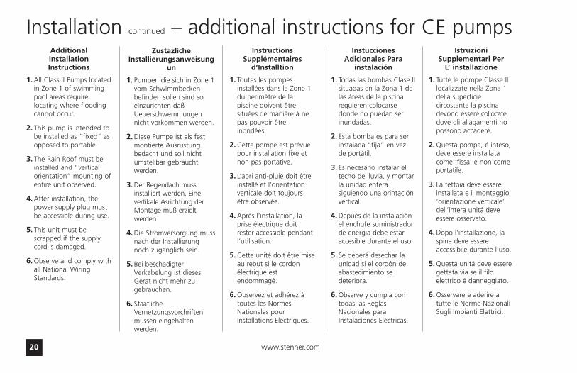
Additional Installation Instructions
1. All Class II Pumps locatedin Zone 1 of swimmingpool areas requirelocating where floodingcannot occur.
2. This pump is intended tobe installed as “fixed” asopposed to portable.
3. The Rain Roof must beinstalled and “verticalorientation” mounting ofentire unit observed.
4. After installation, thepower supply plug mustbe accessible during use.
5. This unit must bescrapped if the supplycord is damaged.
6. Observe and comply withall National WiringStandards.

US and Canada call 1.800.683.2378, other countries call 1.904.641.1666 21
Rain roof slips ontoslots in the wall
mounting bracket. (No tools necessary)
On/Off Switch(Under roof – notvisible this view)
Wall MountingBracket (Requires
2 screws)
DisassembledView
IN(Suction)
OUT(Discharge)
InjectionCheckValve
InjectionTube
SolutionTank
Duckbill
Installation DiagramAlways use rain roof for
outdoor use or
if metering pump issubject to washdowns.
DisassembledView
Grounded PowerOutlet (GFIC
recommended)
InjectionFitting
0-25 psi
InjectionCheck Valve26-100 psi
Shut-OffValve
www.stenner.com22
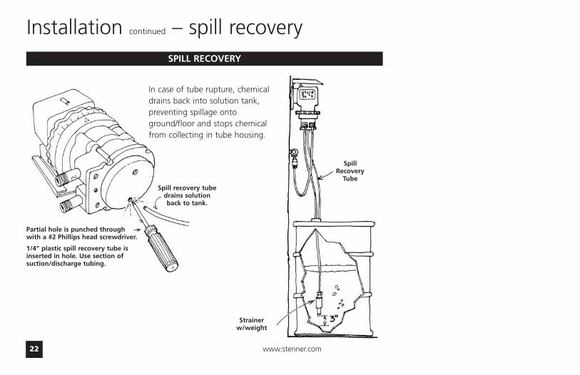
Spill recovery tubedrains solutionback to tank.
Partial hole is punched throughwith a #2 Phillips head screwdriver.
1/4" plastic spill recovery tube isinserted in hole. Use section ofsuction/discharge tubing.
Strainerw/weight
SpillRecovery
Tube
Installation continued – spill recoverySPILL RECOVERY
In case of tube rupture, chemicaldrains back into solution tank,preventing spillage ontoground/floor and stops chemicalfrom collecting in tube housing.
US and Canada call 1.800.683.2378, other countries call 1.904.641.1666 23
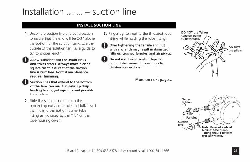
1. Uncoil the suction line and cut a section to assure that the end will be 2-3" above the bottom of the solution tank. Use the outside of the solution tank as a guide to cut to proper length.
Allow sufficient slack to avoid kinks and stress cracks. Always make a cleansquare cut to assure that the suction line is burr free. Normal maintenancerequires trimming.
Suction lines that extend to the bottom of the tank can result in debris pickupleading to clogged injectors and possibletube failure.
2. Slide the suction line through the connecting nut and ferrule and fully insertthe line into the bottom pump tube fitting as indicated by the “IN” on the tube housing cover.
3. Finger tighten nut to the threaded tubefitting while holding the tube fitting.
Over tightening the ferrule and nut with a wrench may result in damagedfittings, crushed ferrules, and air pickup.
Do not use thread sealant tape on pump tube connections or tools to tighten connections.
Installation continued – suction line
DO NOT use Teflontape on pumptube threads.
DO NOTuse pliers.
INSTALL SUCTION LINE
More on next page…
INO
UT
Suctionline
Ferrules
Fingertightennut
Note: Beveled ends offerrules face pump.Tubing should bottominto all fittings.
www.stenner.com24
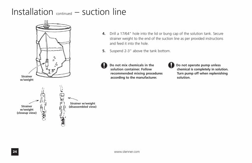
4. Drill a 17/64" hole into the lid or bung cap of the solution tank. Secure strainer weight to the end of the suction line as per provided instructions and feed it into the hole.
5. Suspend 2-3" above the tank bottom.
Installation continued – suction line
Strainer w/weight
Strainer w/weight(disassembled view)Strainer
w/weight(closeup view)
Do not mix chemicals in thesolution container. Followrecommended mixing proceduresaccording to the manufacturer.
Do not operate pump unlesschemical is completely in solution.Turn pump off when replenishingsolution.
US and Canada call 1.800.683.2378, other countries call 1.904.641.1666 25
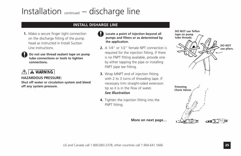
1. Make a secure finger tight connection on the discharge fitting of the pump head as instructed in Install Suction Line instructions.
Do not use thread sealant tape on pumptube connections or tools to tightenconnections.
HAZARDOUS PRESSURE:Shut off water or circulation system and bleedoff any system pressure.
Locate a point of injection beyond allpumps and filters or as determined by the application.
2. A 1/4" or 1/2" female NPT connection is required for the injection fitting. If there is no FNPT fitting available, provide one by either tapping the pipe or installing FNPT pipe tee fitting.
3. Wrap MNPT end of injection fitting with 2 to 3 turns of threading tape. Ifnecessary trim straight-sided extension tip so it is in the flow of water.See Illustration
4. Tighten the injection fitting into the FNPT fitting.
Installation continued – discharge line
DO NOT use Teflontape on pump tube threads.
DO NOTuse pliers.
Trimming Check Valves
INSTALL DISHARGE LINE
More on next page…

www.stenner.com26
Installation continued – discharge line
HAZARDOUS PRESSURE: Shut off water or circulation systemand bleed off any system pressure.
1/4'' or 1/2''FNPT ReductionBushingInjection
Check Valve
Shut-OffValve
Typical Point of Injection
The injection point and fitting requireperiodic maintenance to clean anydeposits or buildup. To allow quick accessto the point of injection, Stennerrecommends the installation of shut-offvalves.
26-100 psi models: • Prior to making tubing connection, test
check valve and NPT threads for leaks by pressurizing system.
• Tighten an additional 1/4 turn if necessary. Make final tube connection as instructed in Install Suction Line instructions.
0-25 psi models:Low-pressure models do not have a check valve and check valve body. Insert the tubing 3/4" to 1" into the injection fittingand make tubing connection as instructedin Install Suction Line instructions.
5. Turn pump switch on and observe chemical flow as actuated by system.
6. After a suitable amount of dosing time, perform tests for required chemical levels. If necessary, fine-tune dosing levels by rotating dial ring (adjustable pumps only).
US and Canada call 1.800.683.2378, other countries call 1.904.641.1666 27
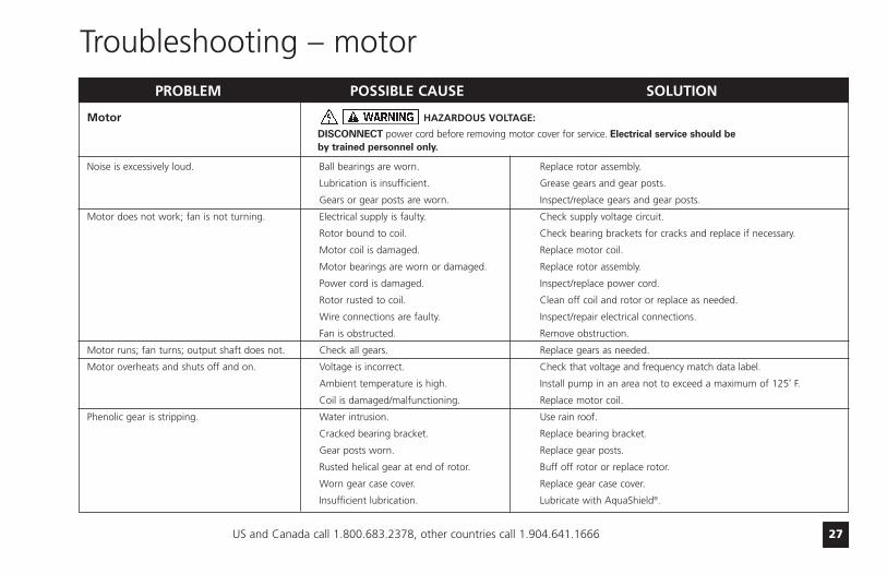
Motor HAZARDOUS VOLTAGE:
DISCONNECT power cord before removing motor cover for service. Electrical service should be by trained personnel only.
Noise is excessively loud. Ball bearings are worn. Replace rotor assembly.
Lubrication is insufficient. Grease gears and gear posts.
Gears or gear posts are worn. Inspect/replace gears and gear posts.
Motor does not work; fan is not turning. Electrical supply is faulty. Check supply voltage circuit.
Rotor bound to coil. Check bearing brackets for cracks and replace if necessary.
Motor coil is damaged. Replace motor coil.
Motor bearings are worn or damaged. Replace rotor assembly.
Power cord is damaged. Inspect/replace power cord.
Rotor rusted to coil. Clean off coil and rotor or replace as needed.
Wire connections are faulty. Inspect/repair electrical connections.
Fan is obstructed. Remove obstruction.
Motor runs; fan turns; output shaft does not. Check all gears. Replace gears as needed.
Motor overheats and shuts off and on. Voltage is incorrect. Check that voltage and frequency match data label.
Ambient temperature is high. Install pump in an area not to exceed a maximum of 125˚ F.
Coil is damaged/malfunctioning. Replace motor coil.
Phenolic gear is stripping. Water intrusion. Use rain roof.
Cracked bearing bracket. Replace bearing bracket.
Gear posts worn. Replace gear posts.
Rusted helical gear at end of rotor. Buff off rotor or replace rotor.
Worn gear case cover. Replace gear case cover.
Insufficient lubrication. Lubricate with AquaShield®.
PROBLEM POSSIBLE CAUSE SOLUTION
Troubleshooting – motor

www.stenner.com28
Feed Rate Control
Adjustment ring will not turn. Variable cam has seized. Grease variable cam and cam slot.
Adjustment ring has seized. Clean and lubricate ring.
Adjustment ring turns, output doesn’t change. Variable cam has disengaged from ring. Re-insert 90˚ end into ring.
Variable cam is broken. Replace variable cam.
Pump head is not rotating. Index plate is worn. Turn over or replace index plate.
Problem with the gear motor. Refer to Motor Section.
Pump head roller assembly is stripped. Replace roller assembly.
Index pin holder backed out of spider assembly. Tighten holder into spider assembly.
Index pin is broken. Replace index pin and lifter assembly.
Pump head rotates continuously. Variable cam is installed incorrectly. Replace or re-insert variable cam.
Indexing is erratic. Index plate is worn. Turn over or replace index plate.
Variable cam is worn. Replace variable cam.
Lifter is worn. Replace index pin and lifter assembly.
PROBLEM POSSIBLE CAUSE SOLUTION
Troubleshooting continued – feed rate control

US and Canada call 1.800.683.2378, other countries call 1.904.641.1666 29
Pump Head
Components are cracking. Chemical attack. Check chemical compatibility.
Visible fluid in pump head. Pump tube rupture/leak. Replace pump tube and ferrules and center tube.
No pump output; pump head rotates. Depleted solution tank. Replenish solution.
Pump suction line weight is above solution. Maintain suction line 2-3" off bottom of tank.
Suction line leak. Inspect or replace suction line.
Ferrules installed incorrectly or damaged. Replace compression ferrules.
Injection point is clogged. Inspect and clean injection point.
Clogged suction/discharge tubing and/orinjection check valve. Clean and/or replace as necessary.
Life of pump tube is exhausted. Replace pump tube.
Low pump output; pump head rotates. Pump tube is worn. Replace pump tube.
Rollers missing or cracked. Install new rollers or roller assembly.
Injection point is restricted. Inspect and clean injection point.
High system back pressure. Check tube psi rating against system pressure; replace accordingly.
No pump output; Roller assembly is stripped. Replace roller assembly.
pump head not rotating. Feed Rate Control problem. Refer to Feed Rate Control section.
Motor problem. Refer to Motor section.
Pump output is high. Incorrect tube size. Replace tube with correct size.
Roller assembly is broken. Replace roller assembly.
Malfunctioning Feed Rate Control. Refer to Feed Rate Control section.
Incorrect model of motor. Replace with proper motor.
PROBLEM POSSIBLE CAUSE SOLUTION
Troubleshooting continued – pump head
www.stenner.com30
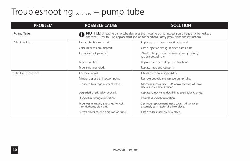
Pump Tube NOTICE: A leaking pump tube damages the metering pump. Inspect pump frequently for leakage and wear. Refer to Tube Replacement section for additional safety precautions and instructions.
Tube is leaking. Pump tube has ruptured. Replace pump tube at routine intervals.
Calcium or mineral deposit. Clean injection fitting, replace pump tube.
Excessive back pressure. Check tube psi rating against system pressure; replace accordingly.
Tube is twisted. Replace tube according to instructions.
Tube is not centered. Replace tube and center it.
Tube life is shortened. Chemical attack. Check chemical compatibility.
Mineral deposit at injection point. Remove deposit and replace pump tube.
Sediment blockage at check valve. Maintain suction line 2-3" above bottom of tank.Use a suction line strainer.
Degraded check valve duckbill. Replace check valve duckbill at every tube change.
Duckbill in wrong orientation. Reverse duckbill orientation.
Tube was manually stretched to lock See tube replacement instructions. Allow rollerinto discharge side slot. assembly to stretch tube into place.
Seized rollers caused abrasion on tube. Clean roller assembly or replace.
PROBLEM POSSIBLE CAUSE SOLUTION
Troubleshooting continued – pump tube
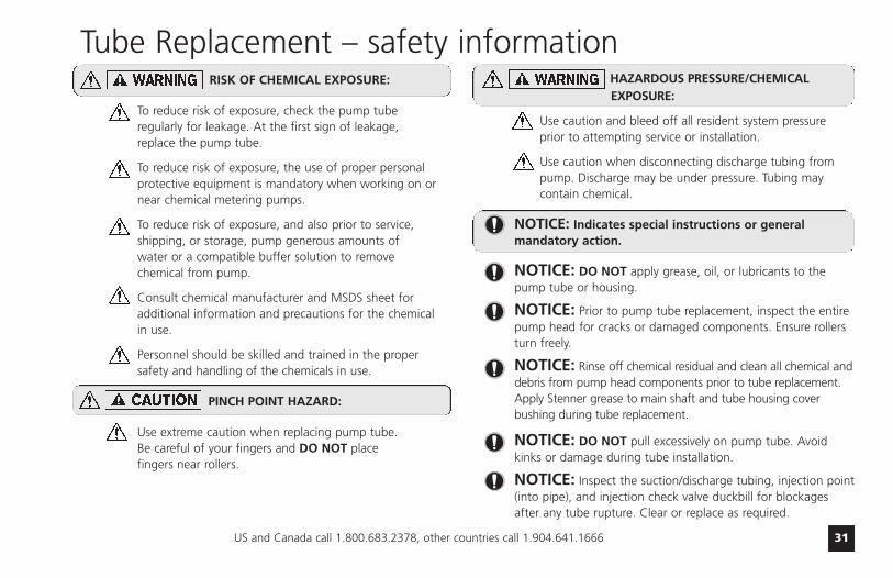
HAZARDOUS PRESSURE/CHEMICAL EXPOSURE:
Use caution and bleed off all resident system pressure prior to attempting service or installation.
Use caution when disconnecting discharge tubing from pump. Discharge may be under pressure. Tubing may contain chemical.
NOTICE: Indicates special instructions or general mandatory action.
NOTICE: DO NOT apply grease, oil, or lubricants to thepump tube or housing.
NOTICE: Prior to pump tube replacement, inspect the entirepump head for cracks or damaged components. Ensure rollersturn freely.
NOTICE: Rinse off chemical residual and clean all chemical anddebris from pump head components prior to tube replacement.Apply Stenner grease to main shaft and tube housing coverbushing during tube replacement.
NOTICE: DO NOT pull excessively on pump tube. Avoidkinks or damage during tube installation.
NOTICE: Inspect the suction/discharge tubing, injection point(into pipe), and injection check valve duckbill for blockagesafter any tube rupture. Clear or replace as required.
US and Canada call 1.800.683.2378, other countries call 1.904.641.1666 31
RISK OF CHEMICAL EXPOSURE:
To reduce risk of exposure, check the pump tube regularly for leakage. At the first sign of leakage, replace the pump tube.
To reduce risk of exposure, the use of proper personal protective equipment is mandatory when working on or near chemical metering pumps.
To reduce risk of exposure, and also prior to service, shipping, or storage, pump generous amounts of water or a compatible buffer solution to remove chemical from pump.
Consult chemical manufacturer and MSDS sheet for additional information and precautions for the chemicalin use.
Personnel should be skilled and trained in the proper safety and handling of the chemicals in use.
PINCH POINT HAZARD:
Use extreme caution when replacing pump tube. Be careful of your fingers and DO NOT place fingers near rollers.
Tube Replacement – safety information

www.stenner.com32
Tube Replacement continued – preparation
1. Follow all safety precautions prior to tubereplacement.
2. Prior to service, pump water or a compatible buffersolution through the pump and suction/discharge lineto remove chemical and avoid contact.
3. Turn pump off.
4. Disconnect the suction and discharge connectionsfrom pump head.
5. Plug power cord into constantly energized, properlygrounded receptacle for service.
US and Canada call 1.800.683.2378, other countries call 1.904.641.1666 33
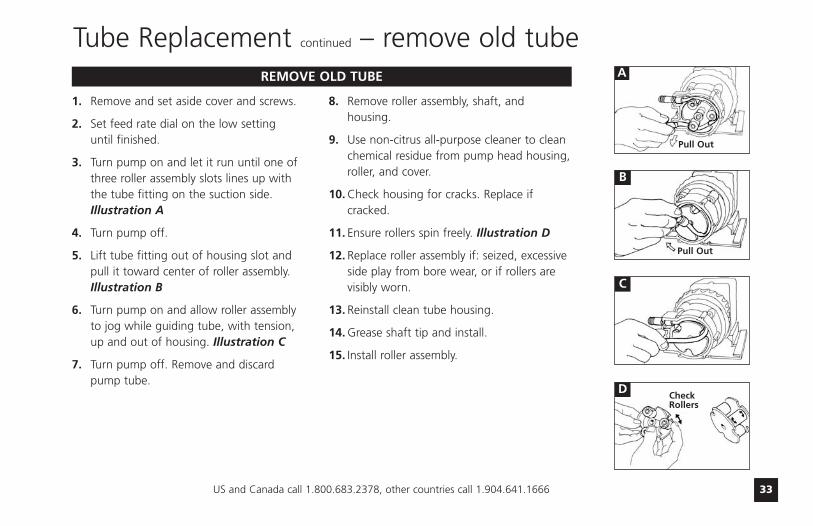
Tube Replacement continued – remove old tube
1. Remove and set aside cover and screws.
2. Set feed rate dial on the low setting until finished.
3. Turn pump on and let it run until one ofthree roller assembly slots lines up with the tube fitting on the suction side. Illustration A
4. Turn pump off.
5. Lift tube fitting out of housing slot and pull it toward center of roller assembly.Illustration B
6. Turn pump on and allow roller assembly to jog while guiding tube, with tension, up and out of housing. Illustration C
7. Turn pump off. Remove and discard pump tube.
8. Remove roller assembly, shaft, andhousing.
9. Use non-citrus all-purpose cleaner to cleanchemical residue from pump head housing,roller, and cover.
10. Check housing for cracks. Replace ifcracked.
11. Ensure rollers spin freely. Illustration D
12. Replace roller assembly if: seized, excessiveside play from bore wear, or if rollers arevisibly worn.
13. Reinstall clean tube housing.
14. Grease shaft tip and install.
15. Install roller assembly.
REMOVE OLD TUBE A
B
C
D
Pull Out
CheckRollers
Pull Out

www.stenner.com34
Tube Replacement continued – install new tube
1. By manually rotating the roller assemblycounter clockwise, align one of three roller assembly slots with the suction sidehousing slot.
2. Place tube fitting into suction side slot ofthe housing and the roller assembly slot.Illustration E
3. With pump setting on low, hold tubefitting and jog roller assembly by turningpump on.
IMPORTANT! Avoid rotating wrist, which canresult in a twisted tube that will not center. Donot force tube and be careful of your fingers.
4. Guide tube, with slight tension (toward the center) to prevent pinching betweenhousing and roller assembly. Illustration F
5. When tube reaches the top housing slot,turn pump off.
6. Turn dial ring to setting 10, hold tubefitting firmly, and turn pump on.
NOTE: A used tube will have stretchedapproximately 3/4" and the new tube willappear to be stiff and short. Follow directionsto allow rollers to stretch tube into place.
7. Allow rollers to stretch tube into placewhile guiding tube into slot. Illustration G
8. Turn pump off.
9. Apply a small amount of grease(AquaShield®) to cover bushing ONLY andreplace cover and two screws, leaving frontscrew in-between the fittings loose.
INSTALL NEW TUBE
E
F
G
NOTE: Cover screws are self-tapping and must bebacked in to locate original thread before securing.If a screw boss is stripped, use alternate bossesand position opposite from each other. Neversecure the cover plate with more than 2 screws.
IMPORTANT! Do not lubricatepump tube or roller assembly.
Roller AssemblySlot
Turn the pumpon, walk tube in.
Roller AssemblySlot
Guide
Guide
Tube Housing
Slot
TubeHousing
Slot
US and Canada call 1.800.683.2378, other countries call 1.904.641.1666 35
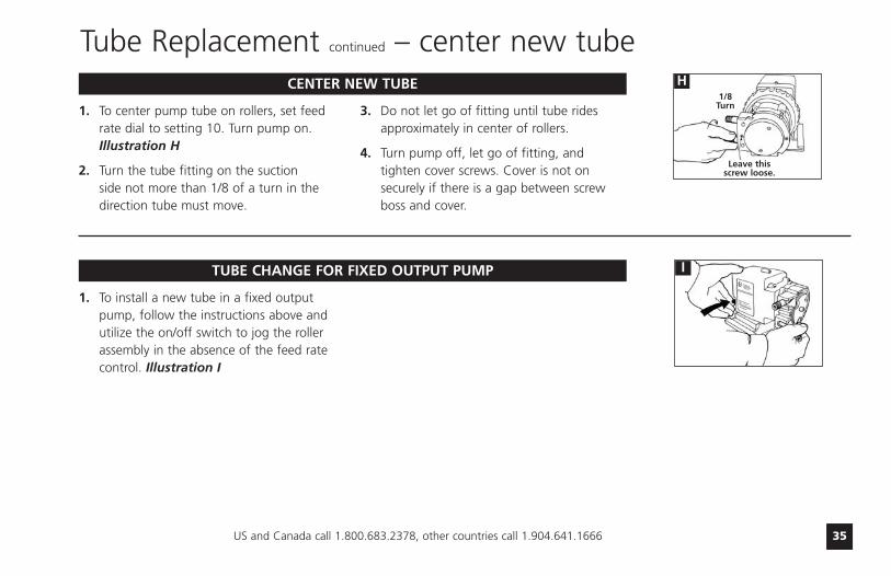
Tube Replacement continued – center new tube
1. To center pump tube on rollers, set feedrate dial to setting 10. Turn pump on.Illustration H
2. Turn the tube fitting on the suction side not more than 1/8 of a turn in thedirection tube must move.
3. Do not let go of fitting until tube ridesapproximately in center of rollers.
4. Turn pump off, let go of fitting, andtighten cover screws. Cover is not onsecurely if there is a gap between screwboss and cover.
CENTER NEW TUBE H1/8
Turn
Leave thisscrew loose.
1. To install a new tube in a fixed outputpump, follow the instructions above andutilize the on/off switch to jog the rollerassembly in the absence of the feed ratecontrol. Illustration I
TUBE CHANGE FOR FIXED OUTPUT PUMP I
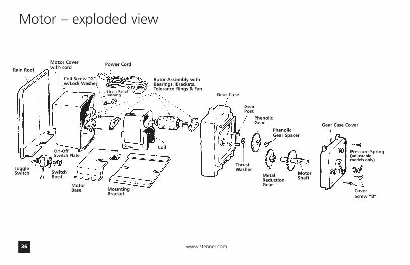
www.stenner.com36
Gear Case Cover
MotorShaftMetal
ReductionGear
ThrustWasher
GearPost
Rain Roof
ToggleSwitch Switch
Boot
MountingBracket
Coil
Motor – exploded view
On-OffSwitch Plate
MotorBase
Power Cord
Strain ReliefBushing
Rotor Assembly withBearings, Brackets,Tolerance Rings & Fan
Gear Case
PhenolicGear
PhenolicGear Spacer
Pressure Spring(adjustable models only)
CoverScrew “B”
Coil Screw “G”w/Lock Washer
Motor Coverwith cord
US and Canada call 1.800.683.2378, other countries call 1.904.641.1666 37
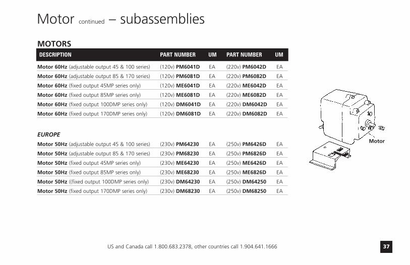
Motor continued – subassemblies
MOTORSDESCRIPTION PART NUMBER UM PART NUMBER UM
Motor 60Hz (adjustable output 45 & 100 series) (120v) PM6041D EA (220v) PM6042D EA
Motor 60Hz (adjustable output 85 & 170 series) (120v) PM6081D EA (220v) PM6082D EA
Motor 60Hz (fixed output 45MP series only) (120v) ME6041D EA (220v) ME6042D EA
Motor 60Hz (fixed output 85MP series only) (120v) ME6081D EA (220v) ME6082D EA
Motor 60Hz (fixed output 100DMP series only) (120v) DM6041D EA (220v) DM6042D EA
Motor 60Hz (fixed output 170DMP series only) (120v) DM6081D EA (220v) DM6082D EA
EUROPE
Motor 50Hz (adjustable output 45 & 100 series) (230v) PM64230 EA (250v) PM6426D EA
Motor 50Hz (adjustable output 85 & 170 series) (230v) PM68230 EA (250v) PM6826D EA
Motor 50Hz (fixed output 45MP series only) (230v) ME64230 EA (250v) ME6426D EA
Motor 50Hz (fixed output 85MP series only) (230v) ME68230 EA (250v) ME6826D EA
Motor 50Hz ((fixed output 100DMP series only) (230v) DM64230 EA (250v) DM64250 EA
Motor 50Hz (fixed output 170DMP series only) (230v) DM68230 EA (250v) DM68250 EA
Motor
www.stenner.com38
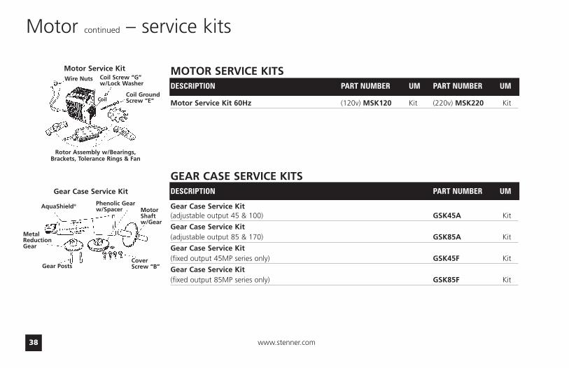
Motor continued – service kits
Rotor Assembly w/Bearings,Brackets, Tolerance Rings & Fan
Coil
Motor Service Kit MOTOR SERVICE KITSDESCRIPTION PART NUMBER UM PART NUMBER UM
Motor Service Kit 60Hz (120v) MSK120 Kit (220v) MSK220 Kit
GEAR CASE SERVICE KITSDESCRIPTION PART NUMBER UM
Gear Case Service Kit (adjustable output 45 & 100) GSK45A Kit
Gear Case Service Kit (adjustable output 85 & 170) GSK85A Kit
Gear Case Service Kit (fixed output 45MP series only) GSK45F Kit
Gear Case Service Kit (fixed output 85MP series only) GSK85F Kit
Wire Nuts Coil Screw “G”w/Lock Washer
Coil GroundScrew “E”Coil
AquaShield® Phenolic Gearw/Spacer Motor
Shaftw/Gear
CoverScrew “B”Gear Posts
MetalReductionGear
Gear Case Service Kit

US and Canada call 1.800.683.2378, other countries call 1.904.641.1666 39
Feed Rate Control – exploded view
Contact factory for part numbers.
FRC Screw
Feed RateMountingPlate
Dial Ring VariableCam
Index PinLifter
Index PinHolder
Index Pin Spring
Index Pin
Index Spider Roller Clutch
O-RingSeal
Index Plate
Feed RateHousing
Main Shaft DoubleHead/Adjustable Output
Main Shaft Dual Head Dual Control/AdjustableOutput
Main Shaft Single Head/Adjustable Output
Mounting Rivet
www.stenner.com40
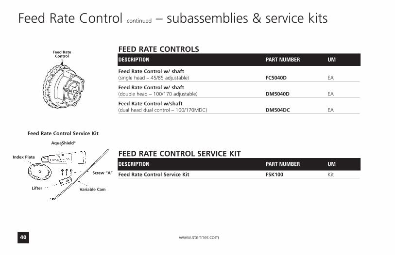
Feed Rate Control continued – subassemblies & service kits
FEED RATE CONTROLSDESCRIPTION PART NUMBER UM
Feed Rate Control w/ shaft(single head – 45/85 adjustable) FC5040D EA
Feed Rate Control w/ shaft(double head – 100/170 adjustable) DM5040D EA
Feed Rate Control w/shaft(dual head dual control – 100/170MDC) DM504DC EA
FEED RATE CONTROL SERVICE KITDESCRIPTION PART NUMBER UM
Feed Rate Control Service Kit FSK100 Kit
Feed RateControl
Index Plate
AquaShield®
Lifter Variable Cam
Screw “A”
Feed Rate Control Service Kit

US and Canada call 1.800.683.2378, other countries call 1.904.641.1666 41
Pump Head – exploded view
Roller
Tube Housing
Roller Housing
Tube HousingCover
PumpTube
CoverScrew “B”
Contact factory for part numbers.

www.stenner.com42
PUMP HEADS
DESCRIPTION PART NUMBER UM PART NUMBER UM
Pump Head includes SANTOPRENE® UCTHC * D EA MCTHC * D PK of 2pump tube; ferrules 1/4" * select tube number 1, 2, 3, 4, 5, 7
Pump Head includes SANTOPRENE® UCPH * FD EA n/a n/apump tube & duckbill; ferrules 1/4" * select tube number 1, 2, 7
Pump Head includes TYGOTHANE® UCPHT0 * EA n/a n/apump tube; ferrules 1/4" * select tube number 2, 5
Pump head includes TYGOTHANE® UCPHTD2 EA n/a n/a#2 pump tube; PELLATHANE® duckbill; ferrules 1/4"
EUROPEPump Head includes SANTOPRENE® UCTH * CE EA MCTH * CE PK of 2pump tube; ferrules 6mm * select tube number 1, 2, 3, 4, 5, 7
Pump Head includes SANTOPRENE® UCPH * CE EA n/a n/apump tube & duckbill; ferrules 6mm * select tube number 1, 2, 7
Pump Head includes TYGOTHANE® UCPHT * CE EA n/a n/apump tube; ferrules 6mm * select tube number 2, 5
Pump head includes TYGOTHANE® UCPHD2CE EA n/a n/a#2 pump tube; PELLATHANE® duckbill; ferrules 6mm
#1 and #2 for 26-100 psi pump (when used with check valve).
#1, 2, 3, 4, 5 for 0-25 psi pump.
#7 tube for 26-100 psi singlehead pump only.
Pump Head continued – subassemblies
Pump Tube Numbers
Pump Head

US and Canada call 1.800.683.2378, other countries call 1.904.641.1666 43
Pump Head continued – service kitsPUMP HEAD SERVICE KITS
DESCRIPTION PART NUMBER UM
SANTOPRENE® Kit (0-25 psi) PSKL0_*_ KIT* select tube number 1, 2, 3, 4, 5
SANTOPRENE® Kit (26 - 100 psi) PSKH0_*_ KIT* select tube number 1, 2, 7
TYGOTHANE® Kit (0-25 psi) PSKLT * KIT* select tube number 2 or 5
KIT: (26-100 psi) TYGOTHANE® #2 Pump Tube PSKHT2 KIT& PELLATHANE® duckbill included
EUROPESANTOPRENE® Kit (1.7 bar) PSKL * CE KIT
* select tube number 1, 2, 3, 4, 5
SANTOPRENE® Kit (1.7-6.9 bar) PSKH * CE KIT* select tube number 1, 2, 7
TYGOTHANE® Kit (1.7 bar) PSKLT * CE KIT* select tube number 2 or 5
KIT: TYGOTHANE® #2 Pump Tube & PSKHT2CE KITPELLATHANE® duckbill included
Pump Tube
0-25 psi/1.7 bar
26-100 psi/6.9 bar
Roller AssemblyConnectingNuts 1/4"
Ferrules 1/4" or6mm Europe
Cover Screw “B”
RollerAssembly
ConnectingNuts 1/4"
DuckbillFerrules 1/4" or6mm EuropeCover Screw “B”
Pump Tube
www.stenner.com44
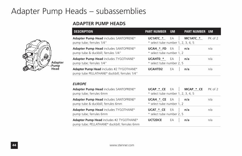
ADAPTER PUMP HEADS
DESCRIPTION PART NUMBER UM PART NUMBER UM
Adapter Pump Head includes SANTOPRENE® UC1ATC * EA MC1ATC * PK of 2pump tube; ferrules 1/4" * select tube number 1, 2, 3, 4, 5
Adapter Pump Head includes SANTOPRENE® UCAH * FD EA n/a n/apump tube & duckbill; ferrules 1/4" * select tube number 1, 2
Adapter Pump Head includes TYGOTHANE® UCAHT0 * EA n/a n/apump tube; ferrules 1/4" * select tube number 2, 5
Adapter Pump Head includes #2 TYGOTHANE® UCAHTD2 EA n/a n/apump tube PELLATHANE® duckbill; ferrules 1/4"
EUROPEAdapter Pump Head includes SANTOPRENE® UCAP * CE EA MCAP * CE PK of 2pump tube; ferrules 6mm * select tube number 1, 2, 3, 4, 5
Adapter Pump Head includes SANTOPRENE® UCAH * CE EA n/a n/apump tube & duckbill; ferrules 6mm * select tube number 1, 2
Adapter Pump Head includes TYGOTHANE® UCAT * CE EA n/a n/apump tube; ferrules 6mm * select tube number 2, 5
Adapter Pump Head includes #2 TYGOTHANE® UCT2DCE EA n/a n/apump tube; PELLATHANE® duckbill; ferrules 6mm
Adapter Pump Heads – subassemblies
AdapterPumpHead

US and Canada call 1.800.683.2378, other countries call 1.904.641.1666 45
Pump TubesPUMP TUBES
DESCRIPTION PART NUMBER UM PART NUMBER UM
SANTOPRENE® Pump Tube UCCP20 * PK of 2 MCCP20 * PK of 5ferrules 1/4" * select tube number 1, 2, 3, 4, 5, 7
SANTOPRENE® Pump Tube & duckbill; UCCP * FD PK of 2 n/a n/aferrules 1/4" * select tube number 1, 2, 7
TYGOTHANE® Pump Tube; UCTYG0 * PK of 2 MCTYG0 * PK of 5ferrules 1/4" * select tube number 2, 5
TYGOTHANE® #2 Pump Tube & UCTY2FD PK of 2 n/a n/aPELLATHANE® duckbill; ferrules 1/4"
EUROPESANTOPRENE® Pump Tube UCCP2 * CE PK of 2 MCCP2 * CE PK of 5ferrules 6mm * select tube number 1, 2, 3, 4, 5, 7
SANTOPRENE® Pump Tube & duckbill; UC * FDCE PK of 2 n/a n/aferrules 6mm * select tube number 1, 2, 7
TYGOTHANE® Pump Tube UCTY * CE PK of 2 MCTY * CE PK of 5ferrules 6mm * select tube number 2, 5
TYGOTHANE® #2 Pump Tube & UCTY2DCE PK of 2 n/a n/aPELLATHANE® duckbill; ferrules 6mm
#1 and #2 for 26-100 psi pump (when used with check valve).
#1, 2, 3, 4, 5 for 0-25 psi pump.
#7 tube for 26-100 psi singlehead pump only.
Pump Tube Numbers

www.stenner.com46
Check Valves
CHECK VALVES
DESCRIPTION PART NUMBER UM PART NUMBER UM
Check Valve includes SANTOPRENE® UCDBINJ EA MCDBINJ PK of 5duckbill; ferrules 1/4"
Check Valve includes PELLATHANE® UCTYINJ EA MCTYINJ PK of 5duckbill; ferrules 1/4"
Check Valve includes SANTOPRENE® UCINJ38 EA MCINJ38 PK of 5duckbill; ferrules 3/8"
Check Valve includes PELLATHANE® UCTYIJ38 EA MCTYIJ38 PK of 5duckbill; ferrules 3/8"
EUROPE
Check Valve includes SANTOPRENE® UCINJCE EA MCINJCE PK of 5duckbill; ferrules 6mm
Check Valve includes PELLATHANE® UCTINJCE EA MCTINJCE PK of 5duckbill; ferrules 6mm
Injection Check Valve 1/4"
Injection Check Valve 3/8"
Injection Check Valve 6mm

US and Canada call 1.800.683.2378, other countries call 1.904.641.1666 47
For Your Records
Model:
Serial Number:
Date of Installation:

Metering PumpsManufactured Since 1957
3174 DeSalvo RoadJacksonville, Florida [email protected]
Phone: 904.641.1666US Toll Free: 800.683.2378Fax: 904.642.1012
Hours of Operation (EST):Mon. – Thu. 7am – 5pmFriday 7am – Noon