installation methods for ipex system 636 type bh pvc and ... 636 installation guide mar 2010.… ·...
TRANSCRIPT
1
Introduction
System 636 PVC and CPVC Type BH Gas Venting Systems are third party certified to ULC S636.
The following installation methods have been prepared in conformity with the requirements of section 4 of ULC Standard S636.
1. Application
IPEX Inc. System 636 PVC and CPVC Gas Venting Systems are intended for negative or positive pressure venting of gas fired appliances
producing exhaust gases having temperatures limited to the range specified in 1(a) and 1(b).
(a) System 636 PVC venting systems are suitable for temperatures up to and including 65°C (149ºF); ULC S636 Class II.
(b) System 636 CPVC venting systems are suitable for temperatures up to and including 90°C (190ºF); ULC S636 Class II.
2. Limiting to Use and Application
(a) Improper installation of System 636 PVC or CPVC systems may result in personal injury or death. Only qualified personnel should
attempt the installation of gas burning equipment, following the gas appliance manufactures' directions.
(b) All System 636 gas venting pipe and fitting must be carefully inspected before use to ensure no damage has occurred during
transportation. Any damaged product must be replaced. No attempt at repairs shall be made at the job site.
(c) The common temperature changes in a gas venting application will cause the system to expand and contract accordingly, proper care
must be taken to allow for this movement through walls, ceilings, and roof penetrations. The venting system must be supported in
accordance with these instructions.
Installation Methods for IPEX System 636®
Type BH PVC and CPVC Gas Venting Systems
IPEX System 636 Installation Methods - Cdn Customers call IPEX Inc. 866.473.9462 - U.S. customers call IPEX USA, LLC 800.463.9572Products manufactured by IPEX Inc. and distributed in the United States by IPEX USA LLC. | System 636® is a trademark of IPEX Branding Inc.
System 636 Pipe, Fittings and Cements are certified as a system and must be installed as such. Differentmanufacturers have different materials, joining systems and adhesives. Do NOT mix pipe, fittings, solvents, or joiningmethods from different BH Vent manufacturers, this can result in unsafe conditions.
System 636 Installation Methods2
(d) Only approved System 636 PVC or CPVC primer and cement shall be used to assemble System 636 PVC or CPVC venting systems.
* All IPEX System 636 cements contain an optical brightener to aid in identification during warranty claims.
Note: Follow IPEX solvent cementing procedures as shown in this manual, and check for proper joint construction when joining pipe to fittings.
(e) Venting should be as direct as possible with a minimum number of fittings. The maximum vertical rise or horizontal run of vent pipe in a
single vent installation shall not exceed the requirements outlined in the appliance manufacturer's installation instructions. The total number
of vent fittings in a single vent installation shall not exceed the requirements outlined in the appliance manufacturer's installation instructions.
(f) All framing requirements for floor and ceiling penetrations shall be in accordance with the local building code and/or the local
regulatory authority.
(g) All penetrations of fire rated floors and/or walls shall be as required by the local building code and/or the local regulatory authority.
All fire stopping of venting shall be completed using fire stops that are listed by a recognized agency. Fire stop installation shall be as
per the fire stop device / system manufacturer's installation instructions.
(h) Roof penetrations should be sealed with a plumbing roof boot or equivalent flashing as per the local building code, or as permitted by
the local regulatory authority.
(i) Chemical attack can cause product failure. Only use PVC/CPVC chemically compatible sealants, gaskets and adhesives.
(j) All framing required in conjunction with wall and roof terminations shall be in accordance with the local building code and/or the local
regulatory authority.
(k) WARNING: Insulation shall not interfere with required clearance spaces.
System 636 Installation Methods 3
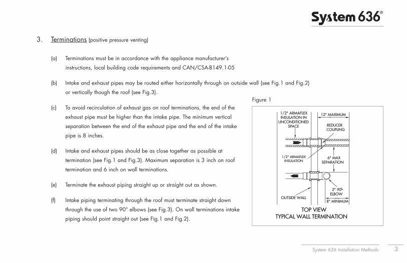
3. Terminations (positive pressure venting)
(a) Terminations must be in accordance with the appliance manufacturer’s
instructions, local building code requirements and CAN/CSA-B149.1-05
(b) Intake and exhaust pipes may be routed either horizontally through on outside wall (see Fig.1 and Fig.2)
or vertically though the roof (see Fig.3).
(c) To avoid recirculation of exhaust gas on roof terminations, the end of the
exhaust pipe must be higher than the intake pipe. The minimum vertical
separation between the end of the exhaust pipe and the end of the intake
pipe is 8 inches.
(d) Intake and exhaust pipes should be as close together as possible at
termination (see Fig.1 and Fig.3). Maximum separation is 3 inch on roof
termination and 6 inch on wall terminations.
(e) Terminate the exhaust piping straight up or straight out as shown.
(f) Intake piping terminating through the roof must terminate straight down
through the use of two 90° elbows (see Fig.3). On wall terminations intake
piping should point straight out (see Fig.1 and Fig.2).
6" MAXSEPARATION
8" MINIMUM
2" 90°ELBOW
12" MAXIMUM
REDUCERCOUPLING
1/2" ARMAFLEXINSULATION IN
UNCONDITIONEDSPACE
1/2" ARMAFLEXINSULATION
OUTSIDE WALL
TOP VIEWTYPICAL WALL TERMINATION
Figure 1
System 636 Installation Methods4
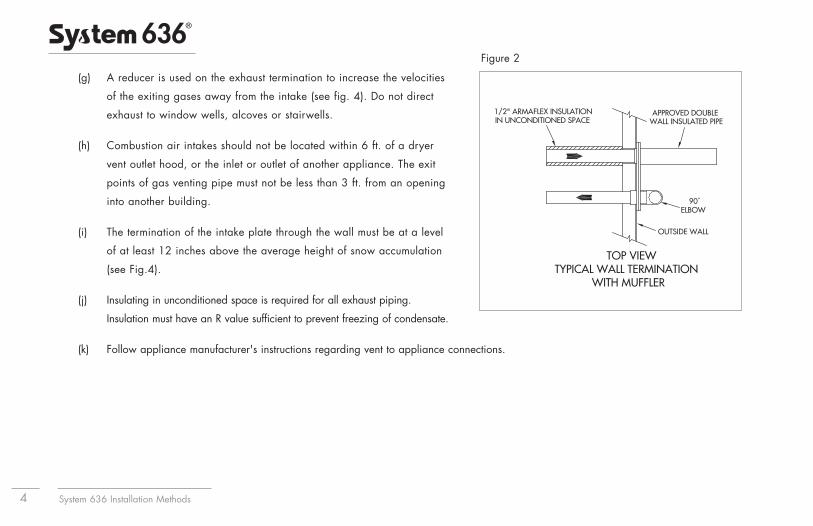
(g) A reducer is used on the exhaust termination to increase the velocities
of the exiting gases away from the intake (see fig. 4). Do not direct
exhaust to window wells, alcoves or stairwells.
(h) Combustion air intakes should not be located within 6 ft. of a dryer
vent outlet hood, or the inlet or outlet of another appliance. The exit
points of gas venting pipe must not be less than 3 ft. from an opening
into another building.
(i) The termination of the intake plate through the wall must be at a level
of at least 12 inches above the average height of snow accumulation
(see Fig.4).
(j) Insulating in unconditioned space is required for all exhaust piping.
Insulation must have an R value sufficient to prevent freezing of condensate.
(k) Follow appliance manufacturer's instructions regarding vent to appliance connections.
TOP VIEWTYPICAL WALL TERMINATION
WITH MUFFLER
1/2" ARMAFLEX INSULATIONIN UNCONDITIONED SPACE
OUTSIDE WALL
90˚ELBOW
APPROVED DOUBLE WALL INSULATED PIPE
Figure 2
System 636 Installation Methods 5
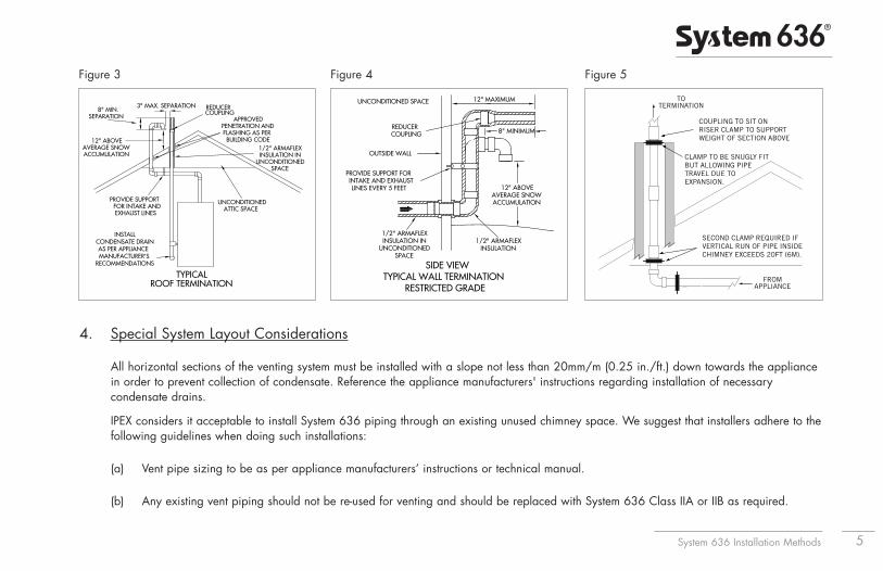
4. Special System Layout Considerations
All horizontal sections of the venting system must be installed with a slope not less than 20mm/m (0.25 in./ft.) down towards the appliancein order to prevent collection of condensate. Reference the appliance manufacturers' instructions regarding installation of necessarycondensate drains.
IPEX considers it acceptable to install System 636 piping through an existing unused chimney space. We suggest that installers adhere to thefollowing guidelines when doing such installations:
(a) Vent pipe sizing to be as per appliance manufacturers’ instructions or technical manual.
(b) Any existing vent piping should not be re-used for venting and should be replaced with System 636 Class IIA or IIB as required.
TYPICAL ROOF TERMINATION
REDUCERCOUPLING
1/2" ARMAFLEXINSULATION IN
UNCONDITIONEDSPACE
UNCONDITIONEDATTIC SPACE
3" MAX. SEPARATION8" MIN.
SEPARATION
12" ABOVEAVERAGE SNOWACCUMULATION
PROVIDE SUPPORTFOR INTAKE ANDEXHAUST LINES
INSTALL CONDENSATE DRAIN AS PER APPLIANCE MANUFACTURER'S
RECOMMENDATIONS
APPROVED PENETRATION AND FLASHING AS PER BUILDING CODE
Figure 3
12" MAXIMUM
8" MINIMUM
12" ABOVEAVERAGE SNOWACCUMULATION
1/2" ARMAFLEXINSULATION
1/2" ARMAFLEXINSULATION IN
UNCONDITIONEDSPACE
SIDE VIEWTYPICAL WALL TERMINATION
RESTRICTED GRADE
UNCONDITIONED SPACE
REDUCERCOUPLING
OUTSIDE WALL
PROVIDE SUPPORT FORINTAKE AND EXHAUSTLINES EVERY 5 FEET
Figure 4
SECOND CLAMP REQUIRED IFVERTICAL RUN OF PIPE INSIDECHIMNEY EXCEEDS 20FT (6M).
FROMAPPLIANCE
TOTERMINATION
CLAMP TO BE SNUGLY FITBUT ALLOWING PIPETRAVEL DUE TO EXPANSION.
COUPLING TO SIT ONRISER CLAMP TO SUPPORTWEIGHT OF SECTION ABOVE
Figure 5
System 636 Installation Methods6
(c) The chimney space should be cleaned prior to installation to remove any debris, creosote, or other material.
(d) All recommended practices for solvent cementing must be observed in the same manner as regular System 636 installations.
(e) Multiple vent pipes are permitted in one chimney space as limited by the interior available cross-sectional area. Zero clearance is
permitted between multiples runs of System 636 piping or other combustibles.
(f) Fresh air intakes may also be installed within existing unused chimney spaces providing acceptable spacing and clearance is obtained
at the termination as per appliance manufacturer requirements.
(g) Terminations at the exit of the chimney space shall be made using acceptable options as per appliance manufacturers’
recommendations.
(h) Vertical piping through the chimney space shall be structurally supported by use of a pipe coupling installed immediately above and
sitting upon a snugly fit pipe clamp. One of these pipe coupling and pipe clamp combinations shall be installed at the entrance or exit
of the chimney space to support the pipe weight. Should the pipe run exceed 60 feet (18 metres) inside the chimney space. Please
contact IPEX for further information.
(i) Consideration should be given to obtaining an air-tight or water-tight seal as required at the chimney exit to prevent entry of water,
snow, moisture or cold air.
System 636 Installation Methods 7
5. Support and Restraint Spacing
(a) General Principles of Support
Adequate support for any piping system is a matter of great importance. In practice, support spacing is a function of pipe size,
operating temperatures, the location of fittings and the mechanical properties of the pipe material.
To ensure satisfactory operation of a thermoplastic piping system, the location and type of hangers should be carefully considered.
The principles of design for steel piping systems are generally applicable to thermoplastic piping systems, but with some notable areas
where special consideration should be exercised.
1. In systems where large fluctuations in temperature occur, allowance must be made for expansion and contraction of the piping
system. Since changes in direction in the system are usually sufficient to allow expansion and contraction, hangers must be placed
so movement is not restricted. (See also Expansion-Contraction section of this manual).
2. Changes in direction (e.g. 90° elbows) should be supported as close as practical to the fitting to avoid introducing excessive
torsional stresses into the system.
3. Supports to be used on System 636 pipe shall be suitable for use on plastic pipe and shall not be tightly clamped onto the pipe
to allow for possible expansion/contraction movement. Pipe clamps or hangers shall not have sharp edges or fulcrum points
which might damage the System 636 pipe over time.
System 636 Installation Methods8
(b) System 636 PVC and CPVC systems must be supported horizontally at a maximum of every 5 feet. This maximum recommendation
should always be referenced against local regulatory codes, the local authority having jurisdiction, as well as the appliance
manufacturer. The most restrictive requirement shall apply. Do not strap vertical vent pipe too tightly. Strapping must support the vent
system while still permitting the vent to move in the event of expansion and contraction.
(c) In order to adequately support the weight of vertical vent pipe, a pipe anchor or support shall be installed at the first floor penetration.
Securely fasten pipe anchors or supports to the building structure. Pipe anchors or supports used for this purpose shall be suitable for
use with plastic pipe. These anchors or supports shall be snuggly fastened to the vent in order to support the weight of the vent, but
shall not be allowed to deform or damage the vent. Anchors or supports supporting the weight of the vertical vent shall be in addition
to the required pipe straps which are intended only to maintain the position of the vertical vent while allowing for expansion and
contraction. Make certain that allowance for expansion and contraction is provided in all venting installations.
(d) System 636 venting shall be supported with steel strapping or equivalent. Strapping shall meet the following requirements.
1/2" strapping - 22 gauge steel
3/4" strapping - 28 gauge steel
3/4" galvanized strapping - 28 gauge steel
Strapping shall be fixed to supporting structure (e.g. floor joists or cross members) using typical framing nails or screws.
(e) System 636 pipe and fittings shall be hung at least 25mm (1") away from any supporting structure to allow for free movement due to
expansion and contraction of the venting system. In certain conditions greater clearance than 25mm (1") may be required between
System 636 venting and supporting structure. Always check the tables in this instruction manual to ensure adequate space is provided
to accommodate expansion and contraction.
System 636 Installation Methods 9
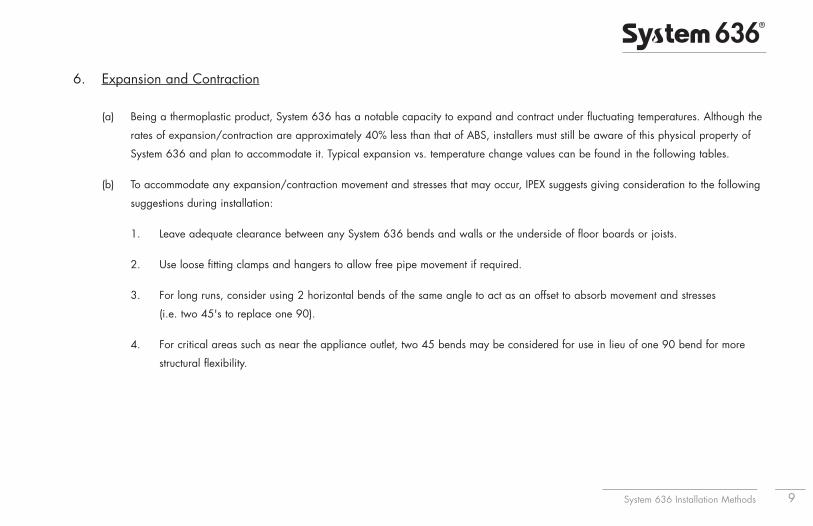
6. Expansion and Contraction
(a) Being a thermoplastic product, System 636 has a notable capacity to expand and contract under fluctuating temperatures. Although the
rates of expansion/contraction are approximately 40% less than that of ABS, installers must still be aware of this physical property of
System 636 and plan to accommodate it. Typical expansion vs. temperature change values can be found in the following tables.
(b) To accommodate any expansion/contraction movement and stresses that may occur, IPEX suggests giving consideration to the following
suggestions during installation:
1. Leave adequate clearance between any System 636 bends and walls or the underside of floor boards or joists.
2. Use loose fitting clamps and hangers to allow free pipe movement if required.
3. For long runs, consider using 2 horizontal bends of the same angle to act as an offset to absorb movement and stresses
(i.e. two 45's to replace one 90).
4. For critical areas such as near the appliance outlet, two 45 bends may be considered for use in lieu of one 90 bend for more
structural flexibility.
System 636 Installation Methods10
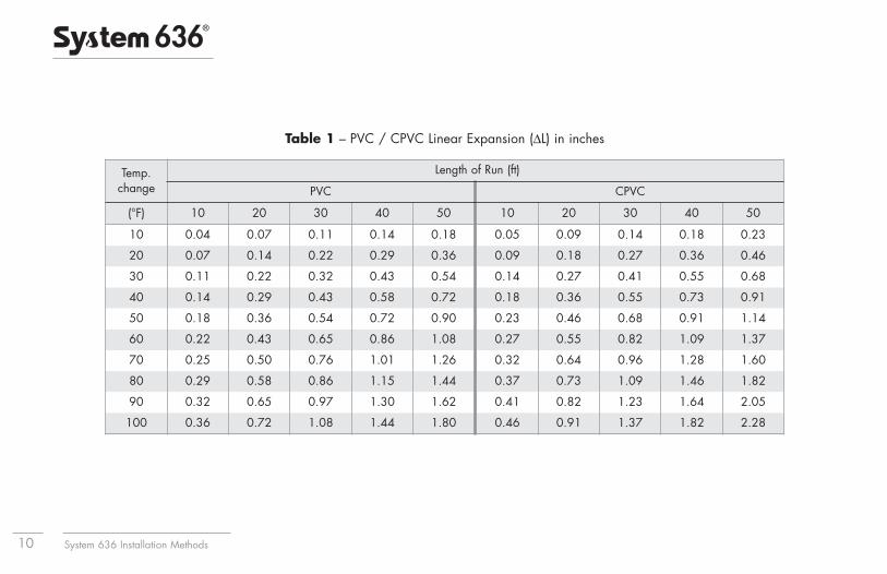
Temp.change
Length of Run (ft)
PVC CPVC
(°F) 10 20 30 40 50 10 20 30 40 50
10 0.04 0.07 0.11 0.14 0.18 0.05 0.09 0.14 0.18 0.23
20 0.07 0.14 0.22 0.29 0.36 0.09 0.18 0.27 0.36 0.46
30 0.11 0.22 0.32 0.43 0.54 0.14 0.27 0.41 0.55 0.68
40 0.14 0.29 0.43 0.58 0.72 0.18 0.36 0.55 0.73 0.91
50 0.18 0.36 0.54 0.72 0.90 0.23 0.46 0.68 0.91 1.14
60 0.22 0.43 0.65 0.86 1.08 0.27 0.55 0.82 1.09 1.37
70 0.25 0.50 0.76 1.01 1.26 0.32 0.64 0.96 1.28 1.60
80 0.29 0.58 0.86 1.15 1.44 0.37 0.73 1.09 1.46 1.82
90 0.32 0.65 0.97 1.30 1.62 0.41 0.82 1.23 1.64 2.05
100 0.36 0.72 1.08 1.44 1.80 0.46 0.91 1.37 1.82 2.28
Table 1 – PVC / CPVC Linear Expansion (ΔL) in inches

System 636 Installation Methods 11
Temp.Change
Length of Run (m)
PVC CPVC
(°C) 3 6 9 12 15 3 6 9 12 15
5 0.81 1.62 2.43 3.24 4.05 1.02 2.04 3.06 4.08 5.10
10 1.62 3.24 4.86 6.48 8.10 2.04 4.08 6.12 8.16 10.20
15 2.43 4.86 7.29 9.72 12.15 3.06 6.12 9.18 12.24 15.30
20 3.24 6.48 9.72 12.96 16.20 4.08 8.00 12.24 16.32 20.40
25 4.05 8.10 12.15 16.20 20.25 5.10 10.20 15.30 20.40 25.50
30 4.86 9.72 14.58 19.44 24.30 6.12 12.24 18.36 24.48 30.60
35 5.67 11.34 17.01 22.68 28.35 7.14 14.28 21.42 28.56 35.70
40 6.48 12.96 19.44 25.92 32.40 8.16 16.32 24.48 32.64 40.80
45 7.29 14.58 21.87 29.16 36.45 9.18 18.36 27.54 36.72 45.90
50 8.10 16.20 24.30 32.40 40.50 10.20 20.40 30.60 40.80 51.00
Table 2 – PVC / CPVC Linear Expansion (ΔL) in mm
System 636 Installation Methods12
7. Firestops
Should System 636 pass through a fire rated floor or wall, the penetration shall be firestopped with a device or system listed to
ULC CAN4-S115 for an F and/or FT Rating equivalent to the hour rating of the floor or wall.
8. Solvent Cementing
(a) Gas Venting Applications
Installation of plastic pipe and fittings for gas venting applications requires a higher degree of skill than other installations; joint failures
in these systems could be life threatening. It is for this reason we recommend the following tips for these applications.
Tips for Installation:
• Installers should complete the IPEX on-line solvent cementing course (www.ipexinc.com)
• Allow at least twice the normal set and cure times.
• Installers should use extra precautions during installation to insure proper installation of system.
• The proper System 636 Cement must be used. Do NOT substitute other cements.
• If there is any doubt about compatibility of materials with a certain appliance or application, the appliance manufacturer
should be contacted.
(b) Do not use solvents or cements other than what is required by this guide. Only IPEX's System 636 PVC/CPVC Primer (purple or clear in
color) shall be used for System 636 PVC or CPVC venting systems. Only System 636 PVC solvent cement (grey in color) or System 636
System 636 Installation Methods 13
CPVC cement (orange in color) shall be used to connect System 636 PVC pipe and fittings. Only IPEX's System 636 CPVC solvent
cement (orange in color) shall be used to connect System 636 CPVC pipe and fittings.
(c) In instances where transitions between material types is necessary, only System 636 Transition Cement shall be used for connections to
ABS. Only System 636 CPVC cement shall be used for transitions between PVC and CPVC.
(d) CPVC solvent cements must not be used more than 2 years beyond the date of manufacture printed on the container. PVC solvent
cements and all primers must not be used more than 3 years beyond the date of manufacture printed on the container.
Basic Principles of Solvent Cementing
To make consistently good joints, the following points should be clearly understood.
1. The joining surfaces must be softened and made semi-fluid.
2. Sufficient cement must be applied to fill the gap between pipe and fitting.
3. Assembly of pipe and fittings must be made while the surfaces are still wet and cement is still fluid.
4. Joint strength develops as the cement dries. In the tight part of the joint the surfaces will tend to fuse together; in the loose part,
the cement will bond to both surfaces.
Penetration and softening can be achieved by the cement itself, by using a suitable primer, or by the use of both primer and cement.
For certain materials and in certain situations, it is necessary to use a primer. A suitable primer will usually penetrate and soften the
surfaces more quickly than cement alone. Additionally, the use of a primer can provide a safety factor for the installer, for they can
know under various temperature conditions when they have achieved sufficient softening. For example, in cold weather more time and
additional applications may be required.

System 636 Installation Methods14
More than sufficient cement to fill the loose part of the joint must be applied. Besides filling the gap, adequate cement layers will
penetrate the surfaces and also remain wet until the joint is assembled.
If the cement coatings on the pipe and fittings are wet and fluid when assembly takes place, they will tend to flow together and become
one cement layer. Also, if the cement is wet, the surfaces beneath them will still be soft and these softened surfaces in the tight part of
the joint will tend to fuse together. As the solvent dissipates, the cement layer and the softened surfaces will harden with a
corresponding increase in joint strength.
In the tight (fused) part of the joint, strength will develop more quickly than in the looser (bonded) part of the joint.
Cement Coatings of Sufficient ThicknessBonded Surfaces
Fused Surfaces
Surfaces must be assembledwhile they are wet and soft
System 636 Installation Methods 15
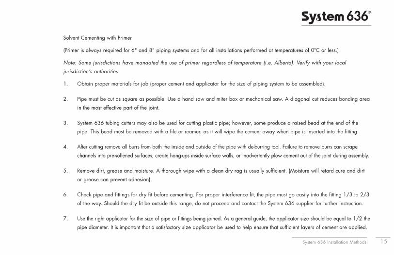
Solvent Cementing with Primer
(Primer is always required for 6" and 8" piping systems and for all installations performed at temperatures of 0ºC or less.)
Note: Some jurisdictions have mandated the use of primer regardless of temperature (i.e. Alberta). Verify with your local
jurisdiction’s authorities.
1. Obtain proper materials for job (proper cement and applicator for the size of piping system to be assembled).
2. Pipe must be cut as square as possible. Use a hand saw and miter box or mechanical saw. A diagonal cut reduces bonding area
in the most effective part of the joint.
3. System 636 tubing cutters may also be used for cutting plastic pipe; however, some produce a raised bead at the end of the
pipe. This bead must be removed with a file or reamer, as it will wipe the cement away when pipe is inserted into the fitting.
4. After cutting remove all burrs from both the inside and outside of the pipe with de-burring tool. Failure to remove burrs can scrape
channels into pre-softened surfaces, create hang-ups inside surface walls, or inadvertently plow cement out of the joint during assembly.
5. Remove dirt, grease and moisture. A thorough wipe with a clean dry rag is usually sufficient. (Moisture will retard cure and dirt
or grease can prevent adhesion).
6. Check pipe and fittings for dry fit before cementing. For proper interference fit, the pipe must go easily into the fitting 1/3 to 2/3
of the way. Should the dry fit be outside this range, do not proceed and contact the System 636 supplier for further instruction.
7. Use the right applicator for the size of pipe or fittings being joined. As a general guide, the applicator size should be equal to 1/2 the
pipe diameter. It is important that a satisfactory size applicator be used to help ensure that sufficient layers of cement are applied.

System 636 Installation Methods16
Priming
8. The use of primer in the solvent cementing process is beneficial as it allows for deeper penetration of the weld after assembly.
Primer is mandatory for usage on System 636 for installation temperatures at or below 0ºC, and for installations of 6" and 8" CPVC
System 636 in all conditions. Certified primer is now available in either purple or clear colors.
9. Using the correct applicator (as outlined in step #7), aggressively work the primer into fitting socket, keeping the surface
and applicator wet until the surface has been softened. More applications may be needed for hard surfaces and cold
weather conditions. Re-dip the applicator in primer as required. When the surface is primed, remove any puddles of primer
from the socket.
10. Next, aggressively work the primer on to the end of the pipe to a point 1/2" beyond the depth of the fitting socket.
11. A second application of primer in the socket is recommended.
12. Immediately and while the surfaces are still wet, apply the appropriate System 636 cement.
13. Cementing; stir the System 636 cement or shake can before using. Using the proper size applicator for the pipe size,
aggressively work a full even layer of cement on to the pipe end equal to the depth of the fitting socket - do not brush it out to a
thin paint type layer, as this will dry within a few seconds.
14. Aggressively work a medium layer of cement into the fitting socket; avoid puddling cement in the socket.
System 636 Installation Methods 17
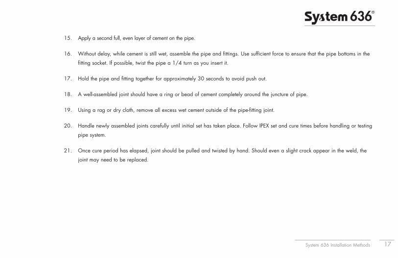
15. Apply a second full, even layer of cement on the pipe.
16. Without delay, while cement is still wet, assemble the pipe and fittings. Use sufficient force to ensure that the pipe bottoms in the
fitting socket. If possible, twist the pipe a 1/4 turn as you insert it.
17. Hold the pipe and fitting together for approximately 30 seconds to avoid push out.
18. A well-assembled joint should have a ring or bead of cement completely around the juncture of pipe.
19. Using a rag or dry cloth, remove all excess wet cement outside of the pipe-fitting joint.
20. Handle newly assembled joints carefully until initial set has taken place. Follow IPEX set and cure times before handling or testing
pipe system.
21. Once cure period has elapsed, joint should be pulled and twisted by hand. Should even a slight crack appear in the weld, the
joint may need to be replaced.
System 636 Installation Methods18
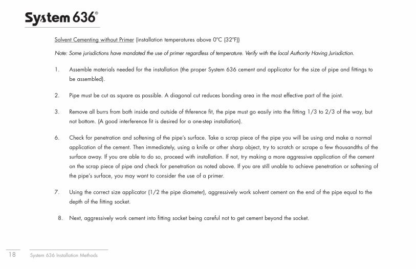
Solvent Cementing without Primer (installation temperatures above 0ºC (32ºF))
Note: Some jurisdictions have mandated the use of primer regardless of temperature. Verify with the local Authority Having Jurisdiction.
1. Assemble materials needed for the installation (the proper System 636 cement and applicator for the size of pipe and fittings to
be assembled).
2. Pipe must be cut as square as possible. A diagonal cut reduces bonding area in the most effective part of the joint.
3. Remove all burrs from both inside and outside of th ference fit, the pipe must go easily into the fitting 1/3 to 2/3 of the way, but
not bottom. (A good interference fit is desired for a one-step installation).
6. Check for penetration and softening of the pipe’s surface. Take a scrap piece of the pipe you will be using and make a normal
application of the cement. Then immediately, using a knife or other sharp object, try to scratch or scrape a few thousandths of the
surface away. If you are able to do so, proceed with installation. If not, try making a more aggressive application of the cement
on the scrap piece of pipe and check for penetration as noted above. If you are still unable to achieve penetration or softening of
the pipe’s surface, you may want to consider the use of a primer.
7. Using the correct size applicator (1/2 the pipe diameter), aggressively work solvent cement on the end of the pipe equal to the
depth of the fitting socket.
8. Next, aggressively work cement into fitting socket being careful not to get cement beyond the socket.
System 636 Installation Methods 19
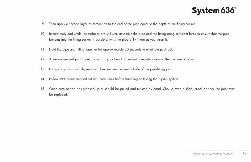
9. Then apply a second layer of cement on to the end of the pipe equal to the depth of the fitting socket.
10. Immediately and while the surfaces are still wet, assemble the pipe and the fitting using sufficient force to ensure that the pipe
bottoms into the fitting socket. If possible, twist the pipe a 1/4 turn as you insert it.
11. Hold the pipe and fitting together for approximately 30 seconds to eliminate push out.
12. A well-assembled joint should have a ring or bead of cement completely around the juncture of pipe.
13. Using a rag or dry cloth, remove all excess wet cement outside of the pipe-fitting joint.
14. Follow IPEX recommended set and cure times before handling or testing the piping system.
15. Once cure period has elapsed, joint should be pulled and twisted by hand. Should even a slight crack appear the joint must
be replaced.

System 636 Installation Methods20
Joining Plastic Pipe in Hot Weather
Solvent cements for plastic pipe contain high-strength solvents which evaporate faster at elevated temperatures. This is especially true when
there is a hot wind blowing. If the pipe is stored in direct sunlight, the pipe surface temperatures may be from 10ºC to 15ºC (20ºF to 30ºF)
higher than the ambient temperature. Solvents soften these hot surfaces faster and deeper, especially inside a joint. Therefore, it is very
important to avoid puddling the cement inside the fitting socket and to wipe off any excess cement outside the joint.
By following our standard instructions and using a little extra care as outlined below, successful solvent cemented joints can be made in even
the most extreme hot weather conditions.
Tips to Follow when Solvent Cementing in High Temperatures:
• Store solvent cements and primers in a cool or shaded area prior to use.
• If possible, store fittings and pipe or at least the ends to be solvent welded, in a shady area before cementing.
• Cool surfaces to be joined by wiping with a damp rag. Make sure that the surface is dry prior to applying solvent cement.
• Try to do the solvent cementing in cooler morning hours.
• Make sure that both surfaces to be joined are still wet with cement when putting them together.
System 636 Installation Methods 21
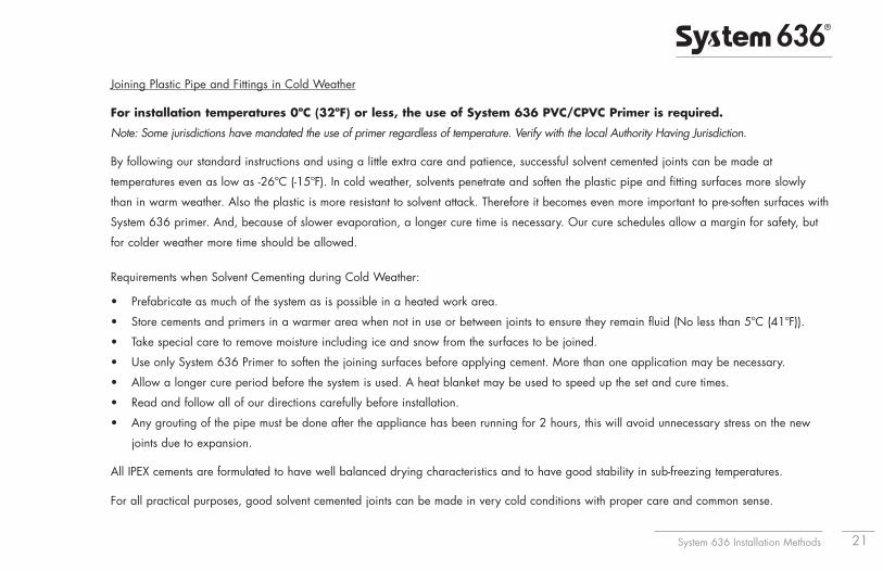
Joining Plastic Pipe and Fittings in Cold Weather
For installation temperatures 0ºC (32ºF) or less, the use of System 636 PVC/CPVC Primer is required.
Note: Some jurisdictions have mandated the use of primer regardless of temperature. Verify with the local Authority Having Jurisdiction.
By following our standard instructions and using a little extra care and patience, successful solvent cemented joints can be made at
temperatures even as low as -26ºC (-15ºF). In cold weather, solvents penetrate and soften the plastic pipe and fitting surfaces more slowly
than in warm weather. Also the plastic is more resistant to solvent attack. Therefore it becomes even more important to pre-soften surfaces with
System 636 primer. And, because of slower evaporation, a longer cure time is necessary. Our cure schedules allow a margin for safety, but
for colder weather more time should be allowed.
Requirements when Solvent Cementing during Cold Weather:
• Prefabricate as much of the system as is possible in a heated work area.
• Store cements and primers in a warmer area when not in use or between joints to ensure they remain fluid (No less than 5ºC (41ºF)).
• Take special care to remove moisture including ice and snow from the surfaces to be joined.
• Use only System 636 Primer to soften the joining surfaces before applying cement. More than one application may be necessary.
• Allow a longer cure period before the system is used. A heat blanket may be used to speed up the set and cure times.
• Read and follow all of our directions carefully before installation.
• Any grouting of the pipe must be done after the appliance has been running for 2 hours, this will avoid unnecessary stress on the new
joints due to expansion.
All IPEX cements are formulated to have well balanced drying characteristics and to have good stability in sub-freezing temperatures.
For all practical purposes, good solvent cemented joints can be made in very cold conditions with proper care and common sense.
System 636 Installation Methods22
Helpful Hints
A properly cemented joint is the most critical part for a successful installation of plastic venting systems. Here is a list of important points to
remember for solvent cementing:
1. Have you reviewed all of the instructions on the System 636 cement container label?
2. Are you using the proper System 636 cement for the job…for the type and size of pipe and correct fittings to be joined?
3. Do you need to take special precautions because of the unusual weather conditions?
4. Do you have the proper tools and sufficient quantities of System 636 cements and primer, and is the cement in good condition?
5. Be sure to use a large enough applicator to quickly spread cement generously on pipe and fittings and then assemble
immediately.
6. Avoid puddling excess cement inside the socket.
7. Be aware at all times of good safety practices. Solvent cements for pipe and fittings are flammable, so there should be no
smoking or other sources of heat or flame in working or storage areas. Be sure to work only in a well ventilated space and avoid
unnecessary skin contact with all solvents. More detailed safety information is available from IPEX.
System 636 Installation Methods 23
Safety Precautions
For over 40 years, millions of solvent cemented joints have been made with only rare cases of mishap. However, since flammable and toxic
solvents are a part of these products, appropriate safety precautions should be used.
All solvent cements and primers for plastic pipe are flammable and should not be used or stored near heat, spark, open flames and other
sources of ignition. Vapors may ignite explosively. Keep containers closed when not in use and covered as much as possible when in use.
Use in well ventilated area. If confined or partially enclosed, use forced ventilation or NIOSH-approved respirator. Avoid breathing vapors.
Atmospheric levels should be maintained below established exposure limits contained in the product’s Material Safety Data Sheet. If airborne
concentrations exceed those limits, use of NIOSH-approved organic vapor cartridge with full face piece is recommended. The effectiveness of
an air purifying respirator is limited. Use it only for a single, short term exposure. For emergency and other conditions where short-term
exposure guidelines may be exceeded, use an approved positive pressure self-contained breathing apparatus. Do not smoke, eat or drink
while using these products. Avoid contact with skin, eyes and clothing. Wash clothing if contaminated before re-use. May cause eye injury.
Protective equipment such as gloves, goggles and an impervious apron should be used. Keep out of reach of children. Carefully read our
Material Safety Data Sheets and follow all precautions.
First Aid
Inhalation: If ill effects from inhalation, remove to fresh air. If not breathing, give artificial respiration. If breathing is difficult, give oxygen.
Call a physician.
Eye Contact: Flush with plenty of water for 15 minutes and call a physician.
Skin Contact: Wash skin with plenty of soap and water for at least 15 minutes. If irritation develops, get medical attention.
Ingestion: If swallowed give 1 to 2 glasses of water or milk, DO NOT INDUCE VOMITING. Contact physician immediately.
System 636 Installation Methods24
Use Caution with Welding Torches
At construction sites where plastic pipe is being installed or has recently been solvent welded, extreme caution should be taken when using
welding torches or other equipment where sparks may be involved. Flammable vapors from cemented joints sometimes linger within or around
a piping system for some time.
Special care must be taken when using a welding torch around plastic pipe systems in industrial plant areas with little or no air circulation.
In all cases, solvent vapors must be removed by air circulation, purging, or other means prior to the use of welding torches, or other spark or
flame generating equipment or procedures.
Storage and Handling of System 636 Cement and Primer
Store System 636 cement and primer in the shade between 4ºC (40ºF) and 43ºC (110ºF) or as specified on label. Keep away from heat,
spark, open flame and other sources of ignition. Keep container closed when not in use. If the unopened container is subjected to freezing,
it may become extremely thick or gelled. This cement can be placed in a warm area, where after a period of time, it will return to its original,
usable condition. But such is not the case when gelatin has taken place because of actual solvent loss—for example, when the container was
left open too long during use or not properly sealed after use. Cement in this condition should not be used and should be properly discarded.
IPEX solvent cements are formulated to be used “as received” in original containers. Adding thinners or primers to change viscosity is not
recommended. If the cement is found to be jelly-like and not free flowing, it should not be used.
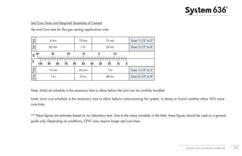
Set/Cure Times and Required Quantities of Cement
Set and Cure time for flue gas venting applications only.
Note: Initial set schedule is the necessary time to allow before the joint can be carefully handled.
Note: Joint cure schedule is the necessary time to allow before commissioning the system. In damp or humid weather allow 50% more
cure time.
** These figures are estimates based on our laboratory tests. Due to the many variables in the field, these figures should be used as a general
guide only. Depending on conditions, CPVC may require longer set/cure times.
System 636 Installation Methods 25
15 min
1 hr
20 min
2 hrs
1 hr
48 hrs
Sizes 1-1/2” to 2”
Sizes 2-1/2” to 8”
Cur
e Ti
me
5 min
30 min
10 min
1 hr
15 min
24 hrs
Sizes 1-1/2” to 2”
Sizes 2-1/2” to 8”Set T
ime
System 636 Installation Methods26
9. Handling and Storage of System 636 Pipe and Fittings
(a) PVC and CPVC are strong, lightweight materials, about one fifth the weight of steel or cast iron. Piping made of this material is easily
handled and, as a result, there is a tendency for them to be thrown about on the jobsite. Care should be taken in handling and storage
to prevent damage to the pipe.
PVC and CPVC pipe should be given adequate support at all times. It should not be stacked in large piles, especially in warm
temperature conditions, as bottom pipe may become distorted and joining will become difficult.
For long-term storage, pipe racks should be used, providing continuous support along the length. If this is not possible, timber supports
of at least 3" bearing width, at spacings not greater than 3' centers, should be placed beneath the piping. If the stacks are rectangular,
twice the spacing at the sides is required. Pipe should not be stored more than seven layers high in racks. If different classes of pipe are
kept in the same rack, pipe with the thickest walls should always be at the bottom. Sharp corners on metal racks should be avoided.
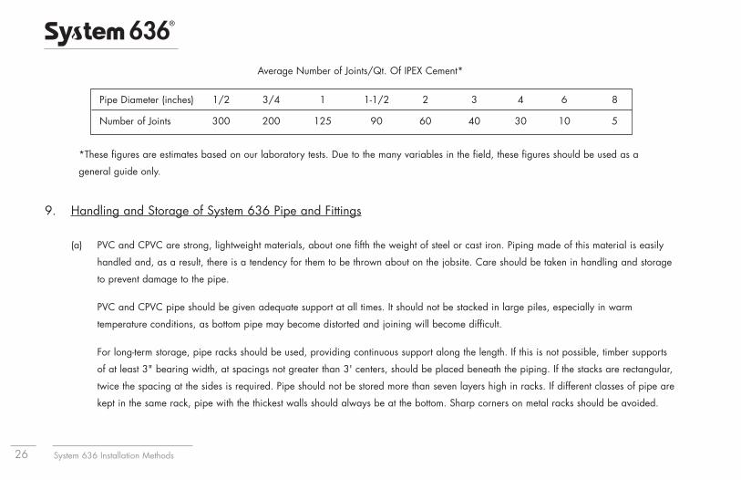
Average Number of Joints/Qt. Of IPEX Cement*
Pipe Diameter (inches) 1/2 3/4 1 1-1/2 2 3 4 6 8
Number of Joints 300 200 125 90 60 40 30 10 5
*These figures are estimates based on our laboratory tests. Due to the many variables in the field, these figures should be used as a
general guide only.
System 636 Installation Methods 27
For temporary storage in the field when racks are not provided, care should be taken that the ground is level and free of sharp objects
(i.e. loose stones, etc.). Pipe should be stacked to reduce movement, but should not exceed three to four layers high.
Since the soundness of any joint depends on the condition of the pipe end, care should be taken in transit, handling and storage to
avoid damage to these ends. The impact resistance and flexibility of both PVC and CPVC pipe are reduced by lower temperature
conditions. The impact strength for both types of piping materials will decrease as temperatures approach 0ºC (32°) and below.
Care should be taken when unloading and handling pipe in cold weather. Dropping pipe from a truck or forklift may cause damage.
Methods and techniques normally used in warm weather may not be acceptable at the lower temperature range.
When loading pipe onto vehicles, care should be taken to avoid contact with any sharp corners (i.e. angle irons, nail heads, etc.),
as the pipe may be damaged.
While in transit, pipe should be well secured and supported over the entire length and should never project unsecured
from the back of a trailer.
b) Prolonged Outdoor Exposure
Prolonged exposure of PVC and CPVC pipe to the direct rays of the sun will not damage the pipe. However, some mild discoloration
may take place in the form of a milky film on the exposed surfaces. This change in color merely indicates that there has been a
harmless chemical transformation at the surface of the pipe. A small reduction in impact strength could occur at the discolored surfaces
but they are of a very small order and are not enough to cause problems in field installation.
System 636 Installation Methods28
(c) Protection – Covering
System 636 PVC and CPVC pipes are packaged in crates and wrapped in protective plastic film, which protects from UV and keeps the
pipe clean. Discoloration of exposed pipe can be avoided by shading it from the direct rays of the sun. This can be accomplished by
covering the stockpile or the crated pipe with a light colored opaque material such as canvas. If the pipe is covered, always allow for
the circulation of air through the pipe to avoid heat buildup in hot summer weather. Make sure that the pipe is not stored close to
sources of heat such as boilers, steam lines, engine exhaust outlets, etc.
(d) System 636 gas venting systems should not be painted. Identification of product material and certifications must be visible for
maintenance and inspection purposes.
10. Statement of the Bases for Acceptance
The acceptance of any gas-fired appliance using IPEX System 636 PVC or CPVC Venting Systems is strictly predicated on the followingconditions:
Condition No. 1 Only System 636 PVC or CPVC components supplied for the job have been used in the installation, with no unauthorized substitutions.
Condition No. 2 The system has been installed in accordance with CSA B149.
Condition No. 3 The appliance manufacturer’s instructions have been followed .
Condition No. 4 IPEX's System 636 installation recommendations have been observed.
Condition No. 5 The authority having jurisdiction (gas inspection authority, building department, fire department, etc.) was consulted before the construction started and that a permit was obtained if necessary.
System 636 Installation Methods 29
11. Maintenance
IPEX recommends that gas appliances using System 636 gas venting systems be checked once a year by a qualified technician.
These recommendations were issued on October 8, 2009 by:
IPEX2441 Royal Windsor Drive, Mississauga, Ontario, Canada, L5J 4C7
and are subject to periodic review.
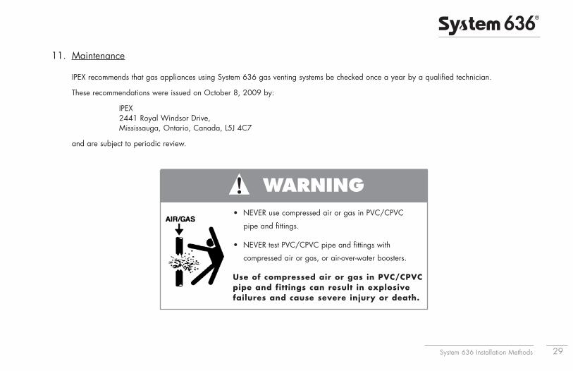
WARNING• NEVER use compressed air or gas in PVC/CPVC
pipe and fittings.
• NEVER test PVC/CPVC pipe and fittings with
compressed air or gas, or air-over-water boosters.
Use of compressed air or gas in PVC/CPVCpipe and fittings can result in explosivefailures and cause severe injury or death.
IPEX System 636 Installation Methods - Cdn Customers call IPEX Inc. 866.473.9462 - U.S. customers call IPEX USA, LLC 800.463.9572Products manufactured by IPEX Inc. and distributed in the United States. by IPEX USA LLC. | System 636® is a trademark of IPEX Branding Inc.
30
Notes
___________________________________________________
___________________________________________________
___________________________________________________
___________________________________________________
___________________________________________________
___________________________________________________
___________________________________________________
___________________________________________________
___________________________________________________
___________________________________________________
___________________________________________________
___________________________________________________
___________________________________________________
___________________________________________________
___________________________________________________
___________________________________________________
IGMESTIP100311 © 2010 IPEX MS0035UC