installation - minn kota motors...installation minnkotamotors.com 7 engine review when selecting a...
TRANSCRIPT

1minnkotamotors.com
Installation
INSTALL ATIONYour Talon comes complete with the items listed below. Please take a moment to familiarize yourself with the parts list and tools needed prior to starting your installation.
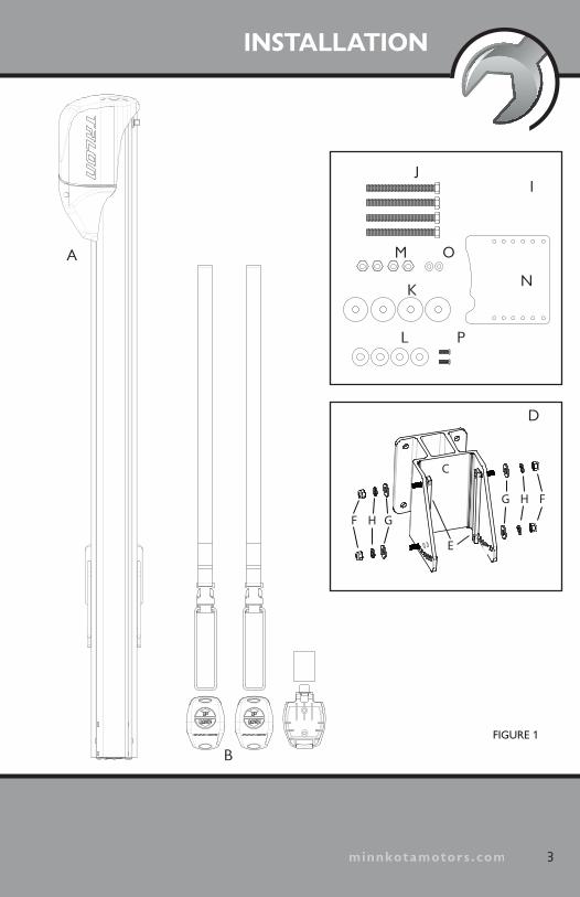
PARTS LIST VIEWA. (1) Anchor Assembly (Includes Power Cable and 30A Fuse Assembly)
B. (2) Remote Control Assemblies w/lanyards and 1 dash mount remote holder
C. (1) Mounting Bracket
D. Mounting Bracket to Anchor Hardware
E. (2) Bracket Sliding Strap Assemblies
F. (4) 5⁄16" x 24 Nylock Nuts
G. (4) 5⁄16" Flat Washers
H. (4) 5⁄16" Lock Washers
I. Mounting Bracket to Transom Hardware
J. (4) 5⁄16" x 3.5" Bolts
K. (4) 5⁄16" Fender Washers
L. (4) 5⁄16" Plain Washers
M. (4) 5⁄16" - 18 Lock Nuts
N. Water Shield
O. (2) #8 SS Flat Washers
P. (2) #8-18 X 5/8 Screws
2 minnkotamotors.com
INSTALLATION
3minnkotamotors.com
FIGURE 1
E
F H G
C
G H F
A
L P
OM
K
I
D
G
HH
B
J
N
HH
minnkotamotors.com4 minnkotamotors.com
Talon Mounting OptionsThere are two mounting options available for installing Talon.
• Direct Transom Mount (Included and recommended)
• Optional Adapter Plate If you're not mounting Talon directly to the transom, you'll need one of our adapter plates to offset the unit from the back of the boat. For more information on adapter plate applications and purchasing, visit minnkotamotors.com.
Your Talon comes complete with the necessary hardware to mount directly to the transom/stern. If you are unable or choose not to drill completely through the transom as recommended, you will need to purchase (4) 5⁄16" lag bolts of the appropriate length.
REQUIRED TOOL LIST
• Drill
• 5⁄16 Drill Bit
• 1⁄2" & 9⁄16" sizes in Wrenches, Ratchet and Sockets
• 3M Marine Adhesive Sealant 5200 (recommended) or Marine Grade Adhesive Sealant
• Wire ties for cable routing
• 4' straight edge or level
• Tape measure
• Torque wrench with up to 30 FT/LB capacity recommended to set vertical adjustment bolt tension

minnkotamotors.com
INSTALLATION
5minnkotamotors.com
6"FIGURE 2
Step 1: Determining a Mounting Location
Your Talon must have a clear unobstructed path to deploy. The Talon mounting bracket included with your unit will allow for approximately 6" of clearance from the transom to the front edge of the deploying anchor. (Figure 2)
Note: The Talon mounting bracket can be mounted directly to the transom (recommended) or to an adapter plate when direct transom mounting is not possible due to obstructions. For more information on adapter plate brackets and other Minn Kota Talon accessories, please visit minnkotamotors.com.
Note: Check to make sure that your proposed location will allow the anchor to deploy without hitting trim tabs, poling platforms, ladders, engine, or other obstructions.
Note: When selecting the Talon mounting bracket mounting location; examine your boat to ensure that you will not drill into any obstructions and that the hardware will be accessible for assembly.

minnkotamotors.com
Port Side (left) or Starboard (right) Mount
While Minn Kota recommends installing your Talon on the port side whenever possible, your Talon is designed to mount on either the port or starboard side of the transom. You should consider your fishing methods when selecting the mounting location. Mounting to the appropriate side will provide the best unobstructed range for casting without having to cast over the boat when anchored. (Figure 3)
Placement of the Talon Mounting Bracket
When mounting the Talon mounting bracket directly to the transom, Minn Kota suggests installing the mounting bracket in the highest possible location. This will provide the most stable support, and the greatest amount of vertical and angular adjustability. The bottom edge of the Talon should never be less than 4" above the bottom line of the hull to prevent spray and drag conditions. (Figure 4)
6 minnkotamotors.com
4"
PORT SIDE
STARBOARD SIDE
FIGURE 3
FIGURE 4

minnkotamotors.com
INSTALLATION
7minnkotamotors.com
Engine Review
When selecting a mounting location make sure that no interference exists between the Talon and your engine during normal operation. Once you have selected your mounting location, trim the engine to its lowest position and steer the engine fully to the side selected. Ensure there is at least 3" of clearance from any point on the Talon. (Figure 5)
3" 3"
FIGURE 5

minnkotamotors.com8 minnkotamotors.com
Platform Review
There are many brands and types of poling platforms available. When choosing a mounting location make sure the platform will not interfere with operation of the Talon . (Figure 6)
Reverse Angle Transom Review
Some boats may be manufactured with a “reverse-transom angle.” In these cases, the Talon mounting bracket may be mounted upside-down as shown to compensate for the reverse angle. (Figure 7)
FIGURE 7
FIGURE 6

minnkotamotors.com
INSTALLATION
9minnkotamotors.com
Step 2: Installing the Talon Mounting Bracket
If you have followed Step 1 carefully and you are installing the mounting bracket directly to the transom, you are now ready to drill holes. Please make one final check to ensure that you have met the requirements for each review and that your drill locations will not encounter any obstructions (lines, hoses, gas tank, etc…).
1. Position the mounting bracket in your selected location and mark the mounting holes. (Figure 8)
2. If using provided mounting hardware, use your 5⁄16" drill bit and carefully drill the marked holes ensur-ing the drill is perpendicular to the transom. (Figure 8)
3. Apply a 1⁄8" bead of 3M 5200 Marine Adhesive Sealant around each of the (4) drilled holes; as well as the perimeter of the Mounting Bracket (staying approximately ½" from the outside edge.)
FIGURE 8

minnkotamotors.com10 minnkotamotors.com
4. Attach the Mounting Bracket to the Transom/Stern using the “Mounting Bracket to Transom Hardware” (J-M.) DO NOT OVERTIGHTEN. (Figure 9)
Step 3: Attaching the Talon to the Mounting Bracket
1. Assemble the (2) Bracket Slid-ing Straps (E) to the primary mounting bracket selecting the using the angular position holes that will be best suited for positioning the Talon as vertically as possible. Assme-ble the “Mounting Bracket to Anchor hardware” (E-H.) (Figure 10) onto the prod-truding stud and tighten lock nuts until threads are just through the nuts. The anchor assembly must be able to freely slide vertically on the straps.
FIGURE 9
FIGURE 10
E
F H G
C
G H F
E
F
FF
H
HH
G
HH
H

minnkotamotors.com
INSTALLATION
11minnkotamotors.com
2. The Anchor Assembly has (2) vertical tracks on either side for vertical adjustment (Figure 11). Two Vertical Stop Adjustment Bolts are included on the starboard (right) side of the Anchor Assembly track. One is to be used above the Primary Mounting Bracket as an operational posi-tion stop. The second is to be used underneath the Primary Mounting Bracket.
3. Carefully lift the Anchor Assembly onto the Mounting Bracket; aligning the tracks with the top of the Bracket Sliding Straps. (Figure 12) Slide the Anchor Assembly down the tracks until the Upper Stop Adjustment Bolt comes in contact with the Mounting Bracket. Ensuring the Stop Adjustment Bolt is loose enough to slide freely; lower the Anchor Assembly to approximately 4" above the bottom of the hull. (Figure 13) Temporarily tighten the
Upper Stop Adjustment Bolt.
FIGURE 11
FIGURE 13
FIGURE 12
Vertical Stop Adjustment Bolt

minnkotamotors.com12 minnkotamotors.com
4. The final adjustment can now be made to the Anchor Assembly. Place a straight edge along the bottom of the hull and measure the distance to the bottom of the Anchor Assembly. Readjust the Upper Stop Adjustment Nut and Anchor Assembly until this dimension is a minimum of 4". Note: Additional adjustments may need to be made after a trial run of the boat.
5. Adjust the angular pitch of the Talon such that the anchor is perpendicular with the horizon by removing the Talon from the Primary Mounting Bracket, then re-positioning the strap as-semblies into the appropriate angular adjustment holes. (See Figure 14)
6. Tighten the (4) Mounting Bracket Hardware (E-H) securely to recommended torque of 20 - 30 FT/LBS.
7. Ensure the Upper and Lower-Stop Nuts are tightened securely.
8. IMPORTANT: Check tension of the 4 vertical adjust-ment nutsafter initial use and periodically there-after to ensure that they are at the recommended torque of 20 - 30 FT/LBS.
FIGURE 14
Angle Adjustment Holes
minnkotamotors.com
INSTALLATION
13minnkotamotors.com
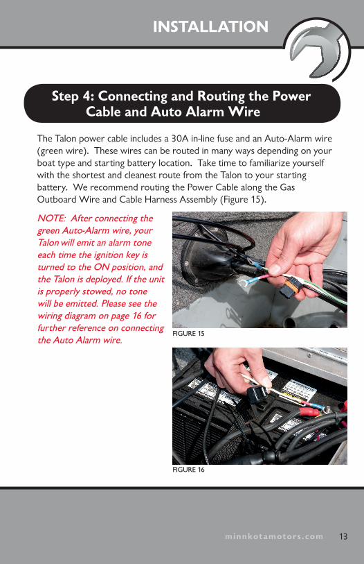
Step 4: Connecting and Routing the Power Cable and Auto Alarm Wire
The Talon power cable includes a 30A in-line fuse and an Auto-Alarm wire (green wire). These wires can be routed in many ways depending on your boat type and starting battery location. Take time to familiarize yourself with the shortest and cleanest route from the Talon to your starting battery. We recommend routing the Power Cable along the Gas Outboard Wire and Cable Harness Assembly (Figure 15).
NOTE: After connecting the green Auto-Alarm wire, your Talon will emit an alarm tone each time the ignition key is turned to the ON position, and the Talon is deployed. If the unit is properly stowed, no tone will be emitted. Please see the wiring diagram on page 16 for further reference on connecting the Auto Alarm wire.
FIGURE 15
FIGURE 16
minnkotamotors.com14 minnkotamotors.com
Note that the Talon does draw a small amount of residual current from the battery even when not in use. If the boat will not be used for more than 30 days, the power leads should be disconnected from the battery.
It is recommended the Talon be connected to the starting battery through a battery selector/Perko-type switch.
The battery selector switch disables power to the Talon when the master switch is OFF. If you are not using a battery selector/Perko-type switch the Talon may be connected directly to the starting battery.
1. If connecting to a battery selector/Perko-type switch, turn it to the off position prior to connecting your power cable.
**ABYC Compliance Note** For proper ABYC compliance, when the factory fuse assembly has been removed (such as when installing a Perko-type switch), the user must install a 30A fuse within 7" of the positive battery terminal.
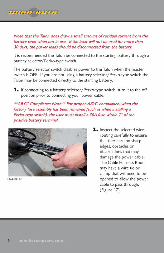
2. Inspect the selected wire routing carefully to ensure that there are no sharp edges, obstacles or obstructions that may damage the power cable. The Cable Harness Boot may have a wire tie or clamp that will need to be opened to allow the power cable to pass through. (Figure 17)
FIGURE 17
minnkotamotors.com
INSTALLATION
15minnkotamotors.com
3. Carefully route the power cable through the Cable Harness Boot to the battery compartment.
4. Carefully remove any slack in the power cable so that it routes cleanly along the Outboard Wire and Cable Harness.
5. Connecting the optional Deployment Alarm: If connecting, the user must install a wire from the switched side of the 12V ignition power back to the Green Auto Alarm Wire. This wire should be no smaller than 18AWG. Cut off the sealed end of the green wire and splice the green wire to the user installed wire. Make sure to use adhesive filled heat shrink to waterproof this splice. Verify that 12VDC is present at this splice when the key switch/ignition of the boat is in the ON position and that no voltage is present when the key switch/ignition of the boat is in the OFF position. When properly connected, this feature will sound an alarm only when the ignition key is turned on AND the Talon is not fully retracted.
6. If not installing the Deployment Alarm, leave the sealed end of the green wire as is.
7. Important: Carefully loosen the battery connection terminals (or battery selector switch connection points) and avoid short-circuiting across the battery posts (or battery selector switch connection points). Connect the white lead with red stripe of the power cable (with 30A in-line fuse) to the starting battery positive (+) (or battery selector switch positive). Connect the black lead of the power cable to the starting battery negative (-) (or battery selector switch negative).
minnkotamotors.com
8. NOTE: There may be other accessories or connections to the starting battery (battery selector switch). Make sure all connections are properly attached and secured.
9. Secure the power cable by using the enclosed wire ties. Excess wire can be stored inside the battery compartment.
16 minnkotamotors.com
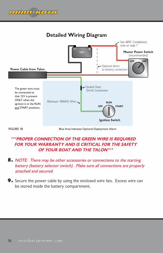
Power Cable from Talon
Master Power Switch(recommended)
Sealed Heat Shrink Connection
Minimum 18AWG Wire
Optional direct to battery connection
See ABYC Compliance note on step 1
The green wire must be connected so that 12V is present ONLY when the ignition is in the RUNand START positions.
Blue Area Indicates Optional Deployment Alarm
OFF ON
12V
Ignition Switch
OFFRUN
START
FIGURE 18
Detailed Wiring Diagram
***PROPER CONNECTION OF THE GREEN WIRE IS REQUIRED FOR YOUR WARRANTY AND IS CRITICAL FOR THE SAFETY
OF YOUR BOAT AND THE TALON***
minnkotamotors.com
INSTALLATION
17minnkotamotors.com
FIGURE 19
FIGURE 20
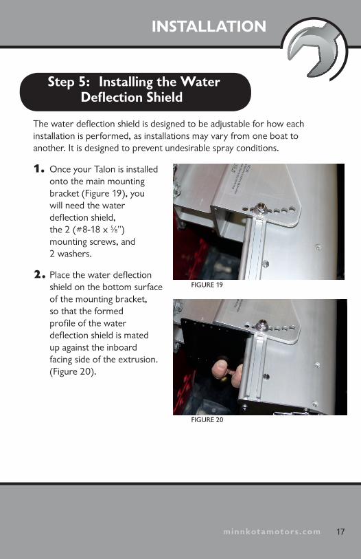
Step 5: Installing the Water Deflection Shield
The water deflection shield is designed to be adjustable for how each installation is performed, as installations may vary from one boat to another. It is designed to prevent undesirable spray conditions.
1. Once your Talon is installed onto the main mounting bracket (Figure 19), you will need the water deflection shield, the 2 (#8-18 x 5⁄8") mounting screws, and 2 washers.
2. Place the water deflection shield on the bottom surface of the mounting bracket, so that the formed profile of the water deflection shield is mated up against the inboard facing side of the extrusion. (Figure 20).

minnkotamotors.com18 minnkotamotors.com
3. Align the closest set of holes on the water deflection shield with the mating holes in the corners of the main mounting bracket, so that the water deflec-tion shield has a slight downward curve to it. (There should be no gap be-tween the water deflection shield and the outer extrusion of the Talon)
4. Install the 2 (#8-18 x 5⁄8") screws, and the 2 washers thru the water deflection shield, and into the corner holes of the main mounting bracket.
**NOTE**If you adjust the angle of your Talon once after step is complete, you will need to readjust the placement of the water deflection shield to ensure proper functionality.
VERIFYING INSTALL ATION1. Carefully inspect the area around the Talon for any obstructions that may in-
terfere with deployment. (For this test your Talon must be able to deploy and make contact with the ground without hitting any obstructions.)
FIGURE 22
Rough Water Mode Indicator Light
Rough Water Mode On/Off ButtonDeploy
Stow
Depth of Deployment Indicator Lights
FIGURE 21

minnkotamotors.com
INSTALLATION
19minnkotamotors.com
2. On the front control panel of the Talon are three (3) switches:
an Auto UP switch , an Auto DOWN switch
and a Rough Water switch .
3. If using a battery selector/Perko-type switch, turn the selector switch to the “on” position.
4. Standing clear of the Talon, push the Auto DOWN switch.
a. The Talon Spike will begin to deploy.
b. When the Spike comes in contact with the ground, the unit will automatically shut off. After the initial shut off, you will hear two (2) additional deploy cycles (or clicks), each 3-seconds apart from the initial ground contact.
c. The Front Panel will display approximately (1) LED light for each foot of Spike deployed. (Figure 23)
d. If the above steps were successful, push the Auto UP switch . The unit will fully retract to the stowed position. No LED lights will be displayed. (Figure 24)
e. If the above steps were not successful, please see the trouble shooting guide on pages 26-27 in the Talon Owners Manual.
f. To perform the same test using the remote instead of the buttons on the control panel, double click the remote DOWN button
to deploy, and single click the remote UP button to retract.
FIGURE 23
FIGURE 24

minnkotamotors.comminnkotamotors.com
minnkotamotors.com
P.O. Box 8129 Mankato, MN 56002
121 Power Drive Mankato, MN 56001 Phone (800) 227-6433Fax (800) 527-4464
2377108 Rev C