installation of bpe-14 wind powered alternator on aeronca...
TRANSCRIPT

Revision Draft – 10 July 18, 2013 Written by John Propst Reviewed by Pending Bill’s review
1
Installation of BPE-14 Wind Powered Alternator on Aeronca Champ
By John Propst with Technical Review by Bill Pancake
Abstract: this article covers the installation of a BPE-14 Wind Powered Alternator on a 1946 Aeronca
Champ.
Background: This article was written to describe details related to the installation of a BPE-14 wind
powered Alternator on Aeronca Champ N3129E. The BPE-14 is approved for
installation on the 7AC and 11AC aircrafts. Installation on the 7AC Champ is
covered by Basic Aircraft Products STC - SA2856SO.
Champ N3129E was rebuilt by the author in 2010. The restoration involved
over 30 337’s of which 16 were Field Approved modifications. The plane
was restored with a C-85-12 engine. The engine had a light weight electric
starter and no engine mounted generator or alternator. The aircraft had a
Field Approved battery powered electrical system to power the starter and
various portable and panel mounted electronic devices such as GPS, Radio, and Engine Analyzer.
The aircraft was specifically restored without an engine-driven electrical system to permit aircraft
operation in and around some controlled airspaces without a transponder. (See FAR Sec.91.215 (b)(3)
for additional details for aircraft without engine-driven electrical system). Wind powered generator and
alternators provides a means to charge a battery powered electrical system while still qualifying for the
transponder exemption for aircraft without an engine-driven electrical system.
Several options for wind power were considered. A Ward wind powered generator was considered. The
author had a new in the box Ward generator that could be used. It was considered less desirable
because:
1. Being a generator rather than an alternator, it was electrically more complex and required an
external voltage regular
2. The Ward generator weighed more that the alternator options being considered, and
3. The Ward generator was out of production with no manufacturing support.
The first wind powered alternator considered was a Gennipod brand aircraft wind powered generator.
This unit is commercially available from a number of sources including Aircraft Spruce. The unit was
considered because of its small size, light weight, and reports of satisfactory performance. The unit was
excluded from consideration because it was not approved for installation on certificated aircraft and we
did not feel comfortable seeking a Field Approval for its installation.
The second wind powered alternator considered was the BPE-14 unit. This unit is also commercially
available from a number of sources including Aircraft Spruce or direct from the manufacturer. This unit

Revision Draft – 10 July 18, 2013 Written by John Propst Reviewed by Pending Bill’s review
2
was considered because of its small size, light weight, and STC approved for installation on Champs.
There were several concerns related to the installation of the BPE-14 unit on a Champ:
1. The first concern is the high cost of the unit. The cost is comparable to costs related to install a
modern new engine driven alternator, and is much more expensive than the experimental
alternator mentioned above.
2. By far the biggest concern was that the unit’s output was limited due to air flow diversion past
the alternator due to the cooling lip on the bottom of the aircraft wraparound (cowling).
3. There were a couple “old” comments on the web that would indicate that the manufacturer’s
technical support was less than desirable.
While the cost is high, the desire to have a non-engine-driven alternator limited the choice to this unit.
I first discussed the air flow concern with Bill Pancake to learn from his experience. Bill had previously
been involved in the installation of several of these units as well as a number of Ward generators. Bill
confirmed that in some cases the lip did create a problem achieving rated output. Bill suggested several
options:
1. Mount the unit on the left oleo landing gear frame where the natural prop wash is directed. Bill
reported that this same issue came up with Ward generators and mounting the Ward generator
on the landing gear frame solved the problem. This installation location is not covered by the
STC.
2. Install a tab on the cooling lip to aid in the airflow to the BPE-14. It has been reported that this
solution improves the performance.
3. Cut a half-moon opening in the center of the cooling lip to permit unobstructed airflow to the
BPE-14 unit. Bill reported that he has seen this option successfully used.
We decided that if this unit was used, we would first mount it as specified by the STC and determine
what output could actually be achieved. The current normal running load is very low and full rated
output would not be required.
In order to move forward on the option of installing a BPE-14 unit, additional information beyond that
presented on the Manufacturer’s website was needed.
I sent an email to the manufacturer requesting additional information such as a copy of the STC,
installation manual, and existing user contact information. I also expressed my concern about airflow
and requested information on this topic. I almost immediately received a reply email from Ron Cox,
company owner. He provided me all the information I requested plus additional information related to
the airflow. He was well aware of the airflow issue and provided drawings and photos on how they and
others had addressed and overcome the issue. Over the next few weeks I had several addition questions
that I emailed to Ron and in every case, I received very quick response that fully addressed my
questions.

Revision Draft – 10 July 18, 2013 Written by John Propst Reviewed by Pending Bill’s review
3
Based on what I considered prompt and complete support from Ron, I ultimately placed an order
directly with Ron. I felt that by dealing directly with the manufacturer, it resulted in faster and better
support and I chose to reward that support by dealing directly with the manufacturer.
The unit is shipped prepainted. Ron is set up to paint the unit with any color shown on the Polyfiber
paint chart. He limits the color selection to the Polyfiber colors to allow the same catalyst and solvent
for all units. My concern was that I had used a Ranthane aerothane paint color that was not on the
Polyfiber chart. After a couple phone calls with Dondi Miller at Polyfiber and Ron, we found out that
Dondi was able to provide Polyfiber paint blended to the Ranthane “Vestal White” color. By working
directly with Dondi and Ron, custom blend paint was provided to match my plane.
The alternator was received completely assembled, painted, and ready for installation. Installation
instructions and other documentation such as the STC were provided with the unit.
To mount the unit, the weight of the aircraft must be removed from the front landing gear so that the
upper axle pivot bolts can be removed and replaced with longer bolts. As shown in the photo on the
right, I fabricated a wooden spreader bar and used and engine hoist and fiber straps to lift the aircraft by
the engine mounting frame. The aircraft
was raised until both wheels were slightly
off the floor.
The two upper axle bolts shown on the
photo above were removed. Undersized
punches were inserted in the holes to
temporarily position the axles in the
bracket. After removing the existing bolts,
new bolts approximately 1/8” longer than
the existing bolts were used to mount the new alternator on the axle attachment bracket as shown in
the photos on the next page.

Revision Draft – 10 July 18, 2013 Written by John Propst Reviewed by Pending Bill’s review
4
The picture below shows the alternator from behind the unit. The hydraulic brake lines are positioned
behind the axles and enter the aircraft through a bulkhead located behind the axle attachment bracket.
The alternator voltage regulator is
located within the mounting
bracket above the alternator
assembly.
The two loose wires coming out
the back of the regulator are the
positive and negative leads that go
to the electrical system.
The wiring diagram shown at the
end of this article shows the
hookup of the alternator. All
wiring was completed with 14
gauge aircraft approved wire and
approved crimp on terminations.
While the installation manual suggests using a grommet for transition of the power leads from the
alternator to the electrical system, a different method was used on this aircraft. Previously, during the
installation of the hydraulic brakes on this aircraft, a transition bulkhead was installed on the aft side of
the axle attachment fittings for the hydraulic brake lines. There was adequate space on this transition
bulkhead to install a cable thru-fitting. The photo on the next page shows the thru fitting. A 3/8” hole
was drilled through both the inner and outer bulkhead plates. A 3/8” continuously threaded pipe was
then installed through the bulkhead plate. Two jam nuts were installed on the inside and outside of the
aircraft. Red thread lock adhesive was installed on the threads as an additional deterrent of the jam nuts
loosening. The leads on the generator had a male crimp-on splicing connector on the positive (+) lead

Revision Draft – 10 July 18, 2013 Written by John Propst Reviewed by Pending Bill’s review
5
and a female crimp-on splicing connector on the negative (-) lead. Mating crimp-on connectors were
installed on the power leads going from the alternator to the aircraft electrical system. Heat shrink
tubing was then installed on each individual splice
connection. In the area where the two power leads
pass through the bulkhead thru fitting, additional
shrink tubing (red) was applied over the two wires.
The leads were then positioned and ty-wrap secured.
The picture below shows the two power leads exiting
through the top of the bulkhead thru fitting. The
negative lead is then routed to the aircraft ground bus
located on the engine side of the firewall. The positive
lead is routed to the + terminal of the panel mounted
0-10 amp DC ammeter. A 10 amp push-pull aircraft
circuit breaker
was mounted
on the aircraft
panel next to existing breakers. A power lead was then installed
from the negative terminal of the panel ammeter to one side of
the circuit breaker. A short lead was then installed from the other
circuit breaker terminal to the positive aircraft bus bar, located on
the other four aircraft circuit breakers.
Revision Draft – 10 July 18, 2013 Written by John Propst Reviewed by Pending Bill’s review
6
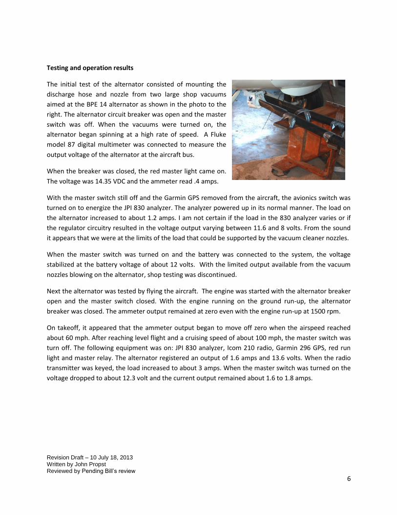
Testing and operation results
The initial test of the alternator consisted of mounting the
discharge hose and nozzle from two large shop vacuums
aimed at the BPE 14 alternator as shown in the photo to the
right. The alternator circuit breaker was open and the master
switch was off. When the vacuums were turned on, the
alternator began spinning at a high rate of speed. A Fluke
model 87 digital multimeter was connected to measure the
output voltage of the alternator at the aircraft bus.
When the breaker was closed, the red master light came on.
The voltage was 14.35 VDC and the ammeter read .4 amps.
With the master switch still off and the Garmin GPS removed from the aircraft, the avionics switch was
turned on to energize the JPI 830 analyzer. The analyzer powered up in its normal manner. The load on
the alternator increased to about 1.2 amps. I am not certain if the load in the 830 analyzer varies or if
the regulator circuitry resulted in the voltage output varying between 11.6 and 8 volts. From the sound
it appears that we were at the limits of the load that could be supported by the vacuum cleaner nozzles.
When the master switch was turned on and the battery was connected to the system, the voltage
stabilized at the battery voltage of about 12 volts. With the limited output available from the vacuum
nozzles blowing on the alternator, shop testing was discontinued.
Next the alternator was tested by flying the aircraft. The engine was started with the alternator breaker
open and the master switch closed. With the engine running on the ground run-up, the alternator
breaker was closed. The ammeter output remained at zero even with the engine run-up at 1500 rpm.
On takeoff, it appeared that the ammeter output began to move off zero when the airspeed reached
about 60 mph. After reaching level flight and a cruising speed of about 100 mph, the master switch was
turn off. The following equipment was on: JPI 830 analyzer, Icom 210 radio, Garmin 296 GPS, red run
light and master relay. The alternator registered an output of 1.6 amps and 13.6 volts. When the radio
transmitter was keyed, the load increased to about 3 amps. When the master switch was turned on the
voltage dropped to about 12.3 volt and the current output remained about 1.6 to 1.8 amps.

Revision Draft – 10 July 18, 2013 Written by John Propst Reviewed by Pending Bill’s review
7
Based on reports by others, an air
deflect was fabricated and installed on
the bottom of the lip on the engine
cowling as shown on the photos to the
right. The theory is that the air deflect
will aid in the diversion of air around
the engine cowling lip to the
alternator. The deflector was
fabricated from .035” 2024-T3
aluminum, 6” X 9”. Three pairs of
miniature vortex generators were
fabricated and attached to the leading
edge of the air deflector. The deflector and vortex
generators were attached with 6-32 aircraft screws
and elastomer nuts. The leading edge of the
deflector was bent into a smooth curve around a
piece of 1” conduit. The trailing edge of the
deflector was aligned with the top of the alternator.
With the deflector and vortex generators installed,
flight tests
confirmed
significant
improvement in
the alternator
output.
Before installing
the deflector, the
ammeter would
not move off of
zero until after
takeoff and about
60 mph. With the
deflector, the
ammeter began to move off zero at about 1500 rpm.
At takeoff the battery voltage was 11.6 volts. After takeoff the battery voltage rose steadily to 13.6 volts.
At 95 mph the unit was putting out 5.4 amps at 13 volts
At 105 mph the unit was putting out 6 amps at 13.3 volts
Vortex Generator
Radio Antenna

Revision Draft – 10 July 18, 2013 Written by John Propst Reviewed by Pending Bill’s review
8
The highest current output observed was about 6.5 amps. Without knowing the characteristics of the
regulator, I assume the regulator is limiting the current as the aircraft battery becomes charged.
Without adding additional load, there is no way to know what the maximum output of the alternator
would be on this aircraft. One potential problem was experienced while testing the alternator. The
following two email messages describe the problem and solution.
Below is an email I sent to Ron Cox related to the alternator tripping off
Ron, I went flying again today and had an experience similar to the one I had yesterday.
I took off and everything seemed to be working good. The voltage prior to takeoff was 11.6 volts. The
alternator put out somewhere around 5.5 amps and the voltage after takeoff increased to 13.2 volts (my
engine analyzer records all data points including voltage every two seconds).
At six minutes into the flight I decided to open the circuit breaker in the alternator output. The output of
course went to zero amps when I opened the circuit breaker. However, when I closed the breaker the
alternator output remained at zero. I continued to fly. Over the next 21 minutes the alternator did not
come on. The Bus voltage gradually decreased to 11.6 volts. When I keyed the radio announcing my arrival
back at our airport the alternator came back on and operated normal. I recalled that yesterday when the
alternator went off after I opened the master switch, it also returned when I keyed the mic on the radio. I
am guessing that in both cases the radio transmission added a sudden load to the aircraft battery.
At this point I have no idea what is happening other than the regulator has some type of protective circuits
in it or the regulator is somehow malfunctioning. I would not expect the alternator to automatically turn
itself off when it is suddenly disconnected from a load. Do you have any thoughts on what is happening
and any possible corrective actions?
John
Below is Ron’s response to my email
Hi John, yes, this is a phenomenon that has showed up in the last 2-3 years. What is happening is
the high voltage cutoff voltage is set (fixed setting) not too far above the regulating voltage. The
regulating voltage is normally set for around 14.5 volts, but when there is an open circuit on the load, the
voltage increases upward somewhat. In some regulators, the high V cutoff point is not very much higher
than the regulating voltage. When you open the CB, it allows the voltage to exceed the high voltage cutoff
point. In practicality, there is no reason to ever open the CB in flight, other than to see what happens. If
you want to do that, just slow the plane down until the voltage comes back on. It is just the nature of the
regulator components. The tolerance on some components is maybe +/- 10%, and if the combination is
just right, the voltage setting is too close to the regulating voltage. I think if you always leave the CB
engaged, this should not happen. There is nothing wrong with the regulator.
Let me know. Ron

Revision Draft – 10 July 18, 2013 Written by John Propst Reviewed by Pending Bill’s review
9
This chart displays the voltage and RPM captured during the flight in which the alternator breaker was
opened and then closed. Note the increase in battery voltage on takeoff (rpm increase). At around 15
minutes the breaker was opened and the battery voltage starts decreasing. At around 37 minutes the
alternator begins operating again. Shortly after the alternator begins working, the aircraft lands.
On a later test, the breaker was opened and the alternator output went to zero. The breaker was then
closed and the output remained at zero. The plane was then gradually slowed. At around 60 mph the
alternator output returned, as Ron had suggested.
One unanticipated issued related to the installation of the BPE-14 alternator was that the close
proximity of the alternator air diversion tab to the Com antenna resulted in the degradation of the radio
signal when the alternator is between the antenna and the other radio. This issue is being addressed by
relocating the Com antenna to the right wing root cover during the upcoming annual inspection.
June 8, 2013
Relocating the Com antenna to the upper wing root cover solved all the radio issues. As the weather
warmed up, I could tell that the air deflector was having an undesired impact on the engine oil
temperature. To solve this issue, I decided to cut a portion of the deflector off and see what effect it
had. I cut 1” off the trailing edge of the deflector. The following flight tests seemed to indicate that the
alternator was still charging OK and that the oil temperature dropped about 10 degrees. I decided to cut
another 1” strip off the trailing edge. Flight tests seemed to indicate that while the alternator output
was less than before, it was still charging the battery at about 4 amps, which was adequate for me and it
appeared that the oil temperature was reduced a bit more. These tests were not very scientific in that

Revision Draft – 10 July 18, 2013 Written by John Propst Reviewed by Pending Bill’s review
10
little data was recorded but my general impression was that the oil temperature returned to an
acceptable level and that the alternator was still charging the battery at an acceptable level.
July 2013
As the ambient temperature increased to the mid 80’s to low 90’s, I was still concerned that the
deflector had some impact on the engine temperature. I decided to totally remove the deflector to see
what impact its removal would have. When it was removed, I noticed that the alternator output
dropped to just over one amp while there was no appreciable change in the engine temperature. This
suggested to me that while the small deflector had little impact on the engine temperature, it did have a
significant impact on the alternator output. Therefore, I reinstalled the small deflector.

Revision Draft – 10 July 18, 2013 Written by John Propst Reviewed by Pending Bill’s review
11
Electrical Loads
Icom A210 - 11.5-27.5V DC (negative ground). Current drain (at 13.8 V DC) Transmit 5A max,
Receive 4A max., 0.5A – Stand-by
Garmin 296 – 11 – 35 VDC, 0.20 amps @ 14 VDC
JPI 830 Analyzer – 10.5 – 35 VDC, 1 amp startup, .5 amp normal
Ipad power consumption approximately 3 watts
Red Light K17-410 – 2 watts
Master Relay (solenoid) – 9 watts
Sky-tech starter -
Electrical Rating of Alternator
6 amps at 80 mph, 9 amps at 100 mph. 14.0 +/- 0.5 VDC
Electrical Schematic Diagram
Start PB
Starter
Master Switch
"Master On" Light
S
P
BatteryConcordeRG 25XC
N-3129E Wiring Diagram
5 A
Master Solenoid
1N4004 Diode across Solenoid
Power Receptacle
Avionics
Icom A210
GPS
Headsets
10 A
Power Receptacle
10 A
5 A
12 v K-4 17-410
10 A W23X1A1G10 Push/Pull Breaker
Intercom
EDM 830
Reg
Alt
BPE 14 Turbo Alternator
VMDigital Voltmeter internal to EDM 830 with alarm
0-10 Amp AnalogAmmeter
A

Revision Draft – 10 July 18, 2013 Written by John Propst Reviewed by Pending Bill’s review
12
Weight and Balance when installed on an Aeronca Champ
The installation instructions for the BPE-14 Model 1008 alternator installed on a Champ indicates that
the units center of gravity is located 1.6” forward of the aft mounting holes as shown below. The unit
weight is listed as 4.0 pounds. As shown below, the aft mounting holes are .88” forward of the face of
the mounting bracket. When using the wing leading edge as the datum for aircraft weight and balance
calculations, the center of the aircraft axle is 1/4” forward of the aircraft datum. Based on dimensions
shown on Aeronca drawings 1-2326 and 7-450, the front face of the axle attachment bracket is located
0.825” forward of the aircraft datum. Therefore the alternator assembly results in a weight of 4 pounds
located 0.825” + .88” + 1.6” = 3.31” forward of the aircraft datum. This yields a moment of 3.31” X 4 lb =
13.22 in-lb.
1.6"
Center of Gravity
.88"