installation of horizontal biological shielding · pdf fileinstallation of horizontal...
TRANSCRIPT

INSTALLATION OF HORIZONTAL BIOLOGICAL SHIELDING
AT THE DRY STORAGE UNIT 3A AT ANDREEVA BAY:
PROBLEMS AND SOLUTIONS
IAEA CEG Workshop, 26 - 27 April 2012, Helsinki
Implementation of International Nuclear Legacy Programmes in Russia

IAEA CEG Workshop
Radiological Improvements to DSU 3A
26 – 27 April 2012, Helsinki2
Outline of presentation
• Background to DSU 3A at Andreeva Bay
• Installation of the temporary cover in 2004
• Development of the design for HBS
• Installation of HBS over DSU 2A and 2B
• Problems and solutions with implementing the design over DSU 3A
• Measures to address predicted exposure to personnel
• Unexpected findings during work implementation
• Results of the work
• Radiation safety
• Conclusions

IAEA CEG Workshop
Radiological Improvements to DSU 3A
26 – 27 April 2012, Helsinki3
Background - Andreeva Bay - North West Russia
• Derelict former Soviet Navy base,
40 kilometres from Norwegian border
• 22,000 Spent Nuclear Fuel assemblies
(~30 tonnes, ~6 tonnes U 235)
• Currently stored in three monolithic
reinforced-concrete tanks of approximately
20 metres in diameter, commonly known as
Dry Storage Units DSU 2A, DSU 2B and
DSU 3A)
• Each tank contains ~1000 x 250mm diameter pipes (cells) up to 5m long which are
surrounded with concrete
• Tanks converted to SNF storage under emergency conditions
DSU 3A
DSU 2A
DSU 2B
IAEA CEG Workshop
Radiological Improvements to DSU 3A
26 – 27 April 2012, Helsinki4
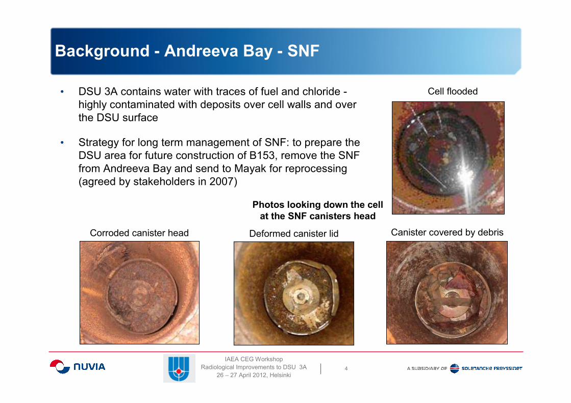
Background - Andreeva Bay - SNF
• DSU 3A contains water with traces of fuel and chloride -
highly contaminated with deposits over cell walls and over
the DSU surface
• Strategy for long term management of SNF: to prepare the
DSU area for future construction of B153, remove the SNF
from Andreeva Bay and send to Mayak for reprocessing
(agreed by stakeholders in 2007)
Cell flooded
Corroded canister head Deformed canister lid Canister covered by debris
Photos looking down the cell
at the SNF canisters head

IAEA CEG Workshop
Radiological Improvements to DSU 3A
26 – 27 April 2012, Helsinki5
Condition of DSU 3A (1999-2005)
3 6 12 24 48 96 192 384 768 1536 3072
Peak radiation EDR
3 mSv/h over concrete beams
42 mSv/h under concrete beams
1999 2005Stabilisation of radiation
levels since installation of
temporary cover in 2004
Effective Dose Rate (EDR) over concrete beams in µSv/h

IAEA CEG Workshop
Radiological Improvements to DSU 3A
26 – 27 April 2012, Helsinki6
Physical condition of DSU 3A (2005-2009)
Above concrete beams in DSU 3A
View under the temporary weatherproof cover
View of the Interspace
between the top of the
DSU and the underside
of the existing concrete
beams
IAEA CEG Workshop
Radiological Improvements to DSU 3A
26 – 27 April 2012, Helsinki7
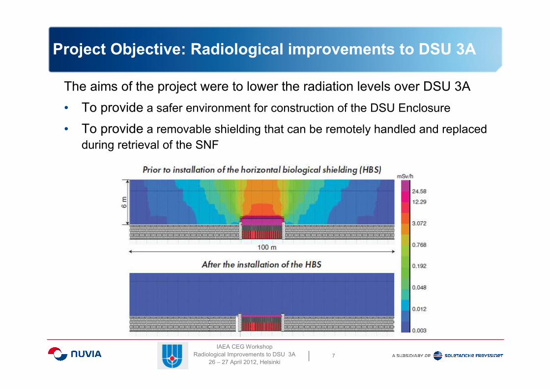
Project Objective: Radiological improvements to DSU 3A
The aims of the project were to lower the radiation levels over DSU 3A
• To provide a safer environment for construction of the DSU Enclosure
• To provide a removable shielding that can be remotely handled and replaced
during retrieval of the SNF

IAEA CEG Workshop
Radiological Improvements to DSU 3A
26 – 27 April 2012, Helsinki8
Design and procurement of Horizontal Biological Shielding
Trials to confirm design parameters
Trials to test handling techniques
Optimal sizing for cell coverage
Installation
frame
Edged with a stepped
profile to make an
effective biological shield

IAEA CEG Workshop
Radiological Improvements to DSU 3A
26 – 27 April 2012, Helsinki9
Condition of DSU 2A before
horizontal shielding in 2008
Shielding installation
Completed in 2009
µSv/h
µSv/h
Installation of HBS on DSU 2A

IAEA CEG Workshop
Radiological Improvements to DSU 3A
26 – 27 April 2012, Helsinki10
Installation of HBS on DSU 2B
• Effective Dose Rate (EDR) reduction factors achieved� 50 – 100 for DSU 2A using 75mm thick steel � 100 – 350 for DSU 2B using 120mm thick steel
• Dose rate normalised for routine operations (<6 µSv/h)
• Installation of shielding was carried out semi-remotely using Bobcat ®
DSU 2B after installation of shielding 2009DSU 2B before installation of shielding 2008

IAEA CEG Workshop
Radiological Improvements to DSU 3A
26 – 27 April 2012, Helsinki11
Advanced procurement of main equipment for DSU 3A
HIAB long reach crane with different grabs for
• Lifting concrete slabs onto waste trolley
• Lifting large debris into containers
• Recovery of the BROKK in case of failure
• Placing light weight covers (caps) over cells
• Placing horizontal biological shielding
BROKK 90 remote manipulator with tools for
• Cutting asphalt
• Jack hammer separation of concrete slabs
• Grab for lifting small debris
• Operating vacuum cleaner to sweep up
dust and debris up to 50mm
BROKK and HIAB
Remotely operable equipment with long
procurement lead times was ordered in
advance, prior to completion of the design
IAEA CEG Workshop
Radiological Improvements to DSU 3A
26 – 27 April 2012, Helsinki12
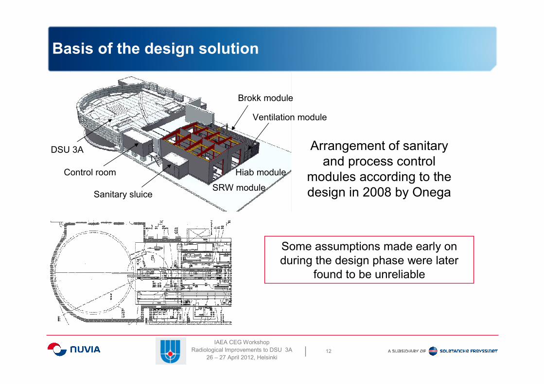
Basis of the design solution
Arrangement of sanitary
and process control
modules according to the
design in 2008 by Onega
Some assumptions made early on
during the design phase were later
found to be unreliable
Brokk module
Hiab module
SRW module
Ventilation module
Control room
Sanitary sluice
DSU 3A
IAEA CEG Workshop
Radiological Improvements to DSU 3A
26 – 27 April 2012, Helsinki13
Contractual arrangements
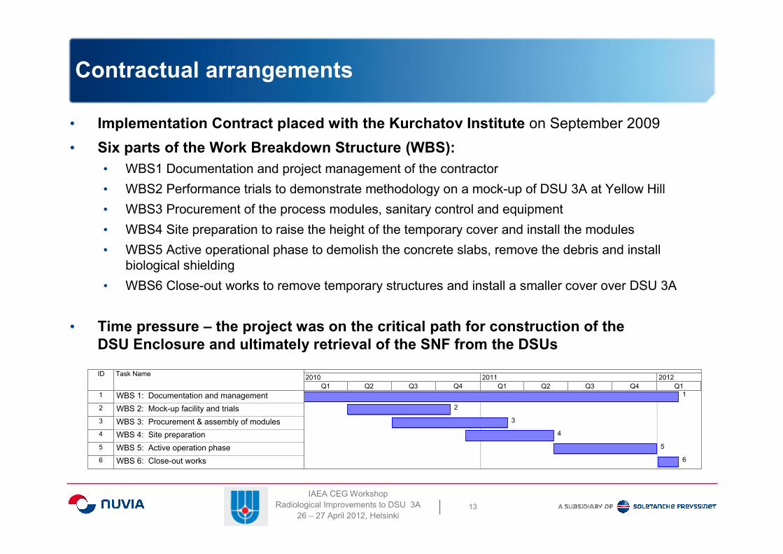
• Implementation Contract placed with the Kurchatov Institute on September 2009
• Six parts of the Work Breakdown Structure (WBS):
• WBS1 Documentation and project management of the contractor
• WBS2 Performance trials to demonstrate methodology on a mock-up of DSU 3A at Yellow Hill
• WBS3 Procurement of the process modules, sanitary control and equipment
• WBS4 Site preparation to raise the height of the temporary cover and install the modules
• WBS5 Active operational phase to demolish the concrete slabs, remove the debris and install
biological shielding
• WBS6 Close-out works to remove temporary structures and install a smaller cover over DSU 3A
• Time pressure – the project was on the critical path for construction of the
DSU Enclosure and ultimately retrieval of the SNF from the DSUs
ID Task Name
1 WBS 1: Documentation and management
2 WBS 2: Mock-up facility and trials
3 WBS 3: Procurement & assembly of modules
4 WBS 4: Site preparation
5 WBS 5: Active operation phase
6 WBS 6: Close-out works
1
2
3
4
5
6
Q1 Q2 Q3 Q4 Q1 Q2 Q3 Q4 Q1
2010 2011 2012

IAEA CEG Workshop
Radiological Improvements to DSU 3A
26 – 27 April 2012, Helsinki14
Challenge: High radiation field during preparatory work
EDR distribution at a height of 0.1m from the cover
Layers of
concrete beams
Concrete beam
supports
underneath
Assumptions about the radiation source term were
needed to calculate thickness of shielding.
Factors of EDR reduction required
over the concrete beams

IAEA CEG Workshop
Radiological Improvements to DSU 3A
26 – 27 April 2012, Helsinki15
Confirmation of EDR during early work (WBS 1)
The calculations of EDR were sensitive to the source model and assumptions.
Original calculations indicated a significant collective dose of 1.7 man Sv.

IAEA CEG Workshop
Radiological Improvements to DSU 3A
26 – 27 April 2012, Helsinki16
Changes implemented at the Preparatory Stage (WBS 4)
Problems and solutions
1. Steel plates were laid over the
concrete beams to provide
supplementary shielding as an
additional safety measure during
the preparatory work (WBS 4)
2. Trials confirmed that the HIAB
boom deflected more than
calculated. The roof needed to be
raised by 1.8 metres.
3. The method of raising the height
of the roof was changed. The
KPM 40 crane was used instead
of jacks.
4. The control room module was
placed in different location to
reduce exposure to workers.
Revised Arrangement

IAEA CEG Workshop
Radiological Improvements to DSU 3A
26 – 27 April 2012, Helsinki17
Challenges during demolition of concrete beams (WBS 5)
1. The brittleness of the concrete beams caused unintentional fragmentation of the waste.
2. A diverse range of wastes and oversized items was discovered after removal of beams.
3. Support columns were bedded on mortar creating bulges on the surface of the DSU.
4. The main equipment was unsuitable to remove large quantities of rubble.
5. The main equipment could not efficiently retrieve waste that had fallen into the cells.
6. The main equipment occasionally failed or was damaged, temporarily stopping all work.
7. The vacuum cleaner frequently clogged with larger pieces of rubble.
8. The quantity of ILW was higher than predicted.
9. Unaccounted waste was discovered between the inner and outer block work walls

IAEA CEG Workshop
Radiological Improvements to DSU 3A
26 – 27 April 2012, Helsinki18
Overcoming the difficulties during the active work (WBS 5)

IAEA CEG Workshop
Radiological Improvements to DSU 3A
26 – 27 April 2012, Helsinki19
Radiation level during placement of HBS (WBS 5)
Effective monitoring
of progress

IAEA CEG Workshop
Radiological Improvements to DSU 3A
26 – 27 April 2012, Helsinki20
Discovery of heavy contamination around the DSU
The gamma camera was used to locate hot spots and could
easily assess the effectiveness of remedial measures

IAEA CEG Workshop
Radiological Improvements to DSU 3A
26 – 27 April 2012, Helsinki21
Remedial measures to achieve EDR target (WBS 5)
Target EDR <12 µSv/h
1. Removal of heavily
contaminated soil and
debris from around the
outside of the DSU.
2. Localisation of major
gamma sources on and
outside the tank using
available shielding
materials.
3. Decontamination of HBS
surface on the tank.
4. Radiological
measurements on the
tank, determination of the
achieved EDR value.
19.01.2012

IAEA CEG Workshop
Radiological Improvements to DSU 3A
26 – 27 April 2012, Helsinki22
Radiation levels during remedial works (WBS 5)
Before and after
additional shielding
IAEA CEG Workshop
Radiological Improvements to DSU 3A
26 – 27 April 2012, Helsinki23
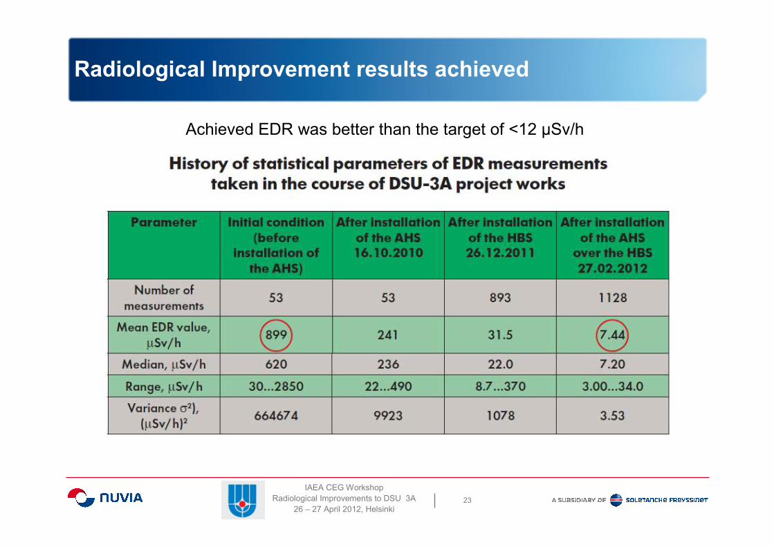
Radiological Improvement results achieved
Achieved EDR was better than the target of <12 µSv/h

IAEA CEG Workshop
Radiological Improvements to DSU 3A
26 – 27 April 2012, Helsinki24
Size reduction of the roof (WBS 6)
100 Te
mobile
crane

IAEA CEG Workshop
Radiological Improvements to DSU 3A
26 – 27 April 2012, Helsinki25
Radiation safety during implementation
• Both the individual and collective doses to personnel were closely
monitored. Measures taken to reduce dose were effective.
• Work was performed according to the principles of ALARA (As Low
As Reasonably Achievable).

IAEA CEG Workshop
Radiological Improvements to DSU 3A
26 – 27 April 2012, Helsinki26
Conclusions
• The aims of the project were achieved
• Horizontal biological shielding is installed over the DSU 3A
• The new cover over the DSU enables the DSU Enclosure to be
constructed safely, ultimately leading to retrieval of the SNF
• The average EDR is 7.44 µSv/h over the tank and 15 µSv/h
around the tank
• Optimisation of the technology helped to minimise exposure of
personnel to radiation
• Problems were overcome mainly through the ingenuity and hard
work of the contractors involved
• Experience using remotely operable equipment with video
systems can be employed for future phases of the work at
Andreeva Bay

IAEA CEG Workshop
Radiological Improvements to DSU 3A
26 – 27 April 2012, Helsinki27
Thank you for your attention.
Any questions?
Спасибо за внимание.
Вопросы?
Nick McAtamney
Ник МакАтамни