installation operation and maintenance manualwebmedia.greenheck.com/iomuser/iom/463687...
TRANSCRIPT
®
READ AND SAVE THESE INSTRUCTIONS
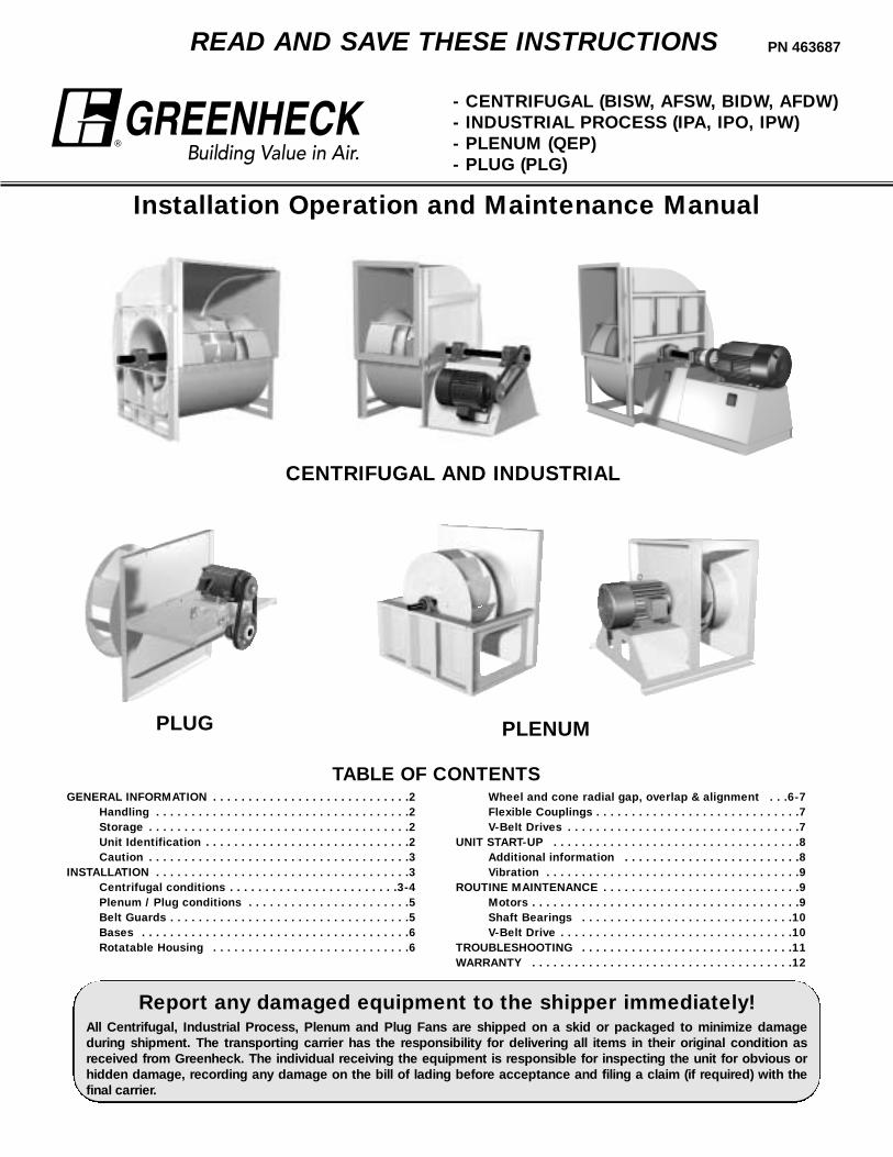
- CENTRIFUGAL (BISW, AFSW, BIDW, AFDW)- INDUSTRIAL PROCESS (IPA, IPO, IPW)- PLENUM (QEP)- PLUG (PLG)
Installation Operation and Maintenance Manual
PN 463687
GENERAL INFORMATION . . . . . . . . . . . . . . . . . . . . . . . . . . . .2Handling . . . . . . . . . . . . . . . . . . . . . . . . . . . . . . . . . . . .2Storage . . . . . . . . . . . . . . . . . . . . . . . . . . . . . . . . . . . . .2Unit Identification . . . . . . . . . . . . . . . . . . . . . . . . . . . . .2Caution . . . . . . . . . . . . . . . . . . . . . . . . . . . . . . . . . . . . .3
INSTALLATION . . . . . . . . . . . . . . . . . . . . . . . . . . . . . . . . . . . .3Centrifugal conditions . . . . . . . . . . . . . . . . . . . . . . . .3-4Plenum / Plug conditions . . . . . . . . . . . . . . . . . . . . . . .5Belt Guards . . . . . . . . . . . . . . . . . . . . . . . . . . . . . . . . . .5Bases . . . . . . . . . . . . . . . . . . . . . . . . . . . . . . . . . . . . . .6Rotatable Housing . . . . . . . . . . . . . . . . . . . . . . . . . . . .6
Report any damaged equipment to the shipper immediately!All Centrifugal, Industrial Process, Plenum and Plug Fans are shipped on a skid or packaged to minimize damageduring shipment. The transporting carrier has the responsibility for delivering all items in their original condition asreceived from Greenheck. The individual receiving the equipment is responsible for inspecting the unit for obvious orhidden damage, recording any damage on the bill of lading before acceptance and filing a claim (if required) with thefinal carrier.
Wheel and cone radial gap, overlap & alignment . . .6-7Flexible Couplings . . . . . . . . . . . . . . . . . . . . . . . . . . . . .7V-Belt Drives . . . . . . . . . . . . . . . . . . . . . . . . . . . . . . . . .7
UNIT START-UP . . . . . . . . . . . . . . . . . . . . . . . . . . . . . . . . . . .8Additional information . . . . . . . . . . . . . . . . . . . . . . . . .8Vibration . . . . . . . . . . . . . . . . . . . . . . . . . . . . . . . . . . . .9
ROUTINE MAINTENANCE . . . . . . . . . . . . . . . . . . . . . . . . . . . .9Motors . . . . . . . . . . . . . . . . . . . . . . . . . . . . . . . . . . . . . .9Shaft Bearings . . . . . . . . . . . . . . . . . . . . . . . . . . . . . .10V-Belt Drive . . . . . . . . . . . . . . . . . . . . . . . . . . . . . . . . .10
TROUBLESHOOTING . . . . . . . . . . . . . . . . . . . . . . . . . . . . . .11WARRANTY . . . . . . . . . . . . . . . . . . . . . . . . . . . . . . . . . . . . .12
TABLE OF CONTENTS
CENTRIFUGAL AND INDUSTRIAL
PLUG PLENUM
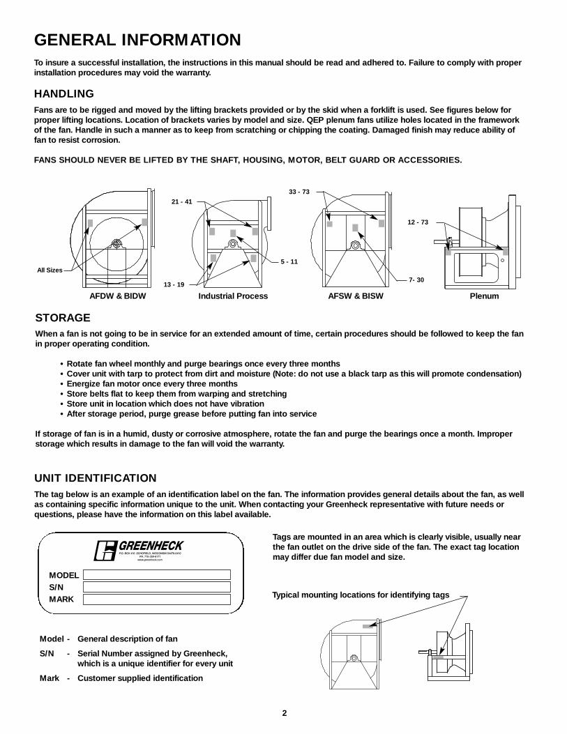
UNIT IDENTIFICATIONThe tag below is an example of an identification label on the fan. The information provides general details about the fan, as wellas containing specific information unique to the unit. When contacting your Greenheck representative with future needs orquestions, please have the information on this label available.
Model - General description of fan
S/N - Serial Number assigned by Greenheck, which is a unique identifier for every unit
Mark - Customer supplied identification
MODELS/NMARK Typical mounting locations for identifying tags
STORAGEWhen a fan is not going to be in service for an extended amount of time, certain procedures should be followed to keep the fanin proper operating condition.
• Rotate fan wheel monthly and purge bearings once every three months• Cover unit with tarp to protect from dirt and moisture (Note: do not use a black tarp as this will promote condensation)• Energize fan motor once every three months• Store belts flat to keep them from warping and stretching• Store unit in location which does not have vibration• After storage period, purge grease before putting fan into service
If storage of fan is in a humid, dusty or corrosive atmosphere, rotate the fan and purge the bearings once a month. Improperstorage which results in damage to the fan will void the warranty.
2
Tags are mounted in an area which is clearly visible, usually nearthe fan outlet on the drive side of the fan. The exact tag locationmay differ due fan model and size.
AFDW & BIDW AFSW & BISW Plenum
All Sizes
7- 30
33 - 73
12 - 73
Industrial Process13 - 19
5 - 11
21 - 41
GENERAL INFORMATIONTo insure a successful installation, the instructions in this manual should be read and adhered to. Failure to comply with properinstallation procedures may void the warranty.
HANDLINGFans are to be rigged and moved by the lifting brackets provided or by the skid when a forklift is used. See figures below forproper lifting locations. Location of brackets varies by model and size. QEP plenum fans utilize holes located in the frameworkof the fan. Handle in such a manner as to keep from scratching or chipping the coating. Damaged finish may reduce ability offan to resist corrosion.
FANS SHOULD NEVER BE LIFTED BY THE SHAFT, HOUSING, MOTOR, BELT GUARD OR ACCESSORIES.

Inlet SpinInlet spin is a frequent cause of reduced fan performance.The change in fan performance is a function of the intensityof spin and not easily defined. The best solution is properduct design and airflow patterns.
Rotation
Rota tion
GOODPOOR
TurningVanes
Inlet Duct TurnsInstallation of a duct turn or elbow too close to the fan inletreduces fan performance because air is loaded unevenlyinto the fan wheel. To achieve full fan performance, thereshould be at least one fan wheel diameter between the turnor elbow and the fan inlet.
1 FanWheelDia.
GOOD POOR
TurningVanes
CENTRIFUGAL AND INDUSTRIAL PROCESS FANS - INSTALLATIONS
Installations with inlet or discharge configurations that deviate from this standard may result in reduced fan performance.Restricted or unstable flow at the fan inlet can cause pre-rotation of incoming air or uneven loading of the fan wheel yieldinglarge system losses and increased sound levels. Free discharge or turbulent flow in the discharge ductwork will also result insystem effect losses. Refer to the following diagrams for the most efficient installation conditions.
INSTALLATION
DUCTED INLET INSTALLATIONS
CAUTION!
When installing a fan, ensure the proper protective devices are used to protect personnel from moving parts and otherhazards. A complete line of protective accessories are available from Greenheck including: inlet guards, outlet guards, beltguards, shaft guards, protective cages and electrical disconnects.
Check local codes to ensure compliance for all protective devices.
For further details on safety practices involving industrial and commercial fans please refer to AMCA Publication 410.
ELECTRICAL DISCONNECTSAll fan motors should have disconnects located in close visual proximity to turn off electrical service. Service disconnectsshall be locked out when maintenance is being performed.
MOVING PARTSAll moving parts must have guards to protect personnel. Refer to local codes for requirements as to the number, type anddesign. Fully secure fan wheel before performing any maintenance. The fan wheel may start “free wheeling” even if allelectrical power has been disconnected. Before the initial start-up or any restart, check the following items to make sure thatthey are installed and secure.
GUARDS (BELT, SHAFT, INLET, OUTLET)Do not operate fans without proper protective devices in place. Failure to do so may result in serious bodily injury and property damage.
ACCESS DOORSBefore opening access doors ensure the fan wheel has stopped moving and that the wheel has been secured from being able to rotate. Do not operate fan without access door in its fully closed position.
AIR PRESSURE AND SUCTIONIn addition to the usual hazards associated with rotating machinery, fans also create a dangerous suction at the inlet. Specialcaution needs to be used when moving around a fan whether it is in operation or not. Before start-up, make sure the inletarea is clear of personnel and loose objects.
3

CENTRIFUGAL - Outdoor Installation for UL/cUL 762 Listed Fans for Restaurant Exhaust
The UL/cUL 762 listing forrestaurant exhaust is available onBISW model. Fans are listed for amaximum operating temperatureof 375°F and include a boltedaccess door and 1 in. drainconnection. An outlet guard isstrongly recommended when thefan discharge is accessible. Anupblast discharge isrecommended. The fan dischargemust be a minimum of 40 in.above the roof line and theexhaust duct must be fullywelded to a distance of 18 in.above the roof surface.
This drawing is for dimensionalinformation only. See the latestedition of NFPA 96 Standard forVentilation Control and Fire Protection of Commercial Cooking Operations for detailed installation instructions, materials, ductconnections and clearances.
40 in.**
18 in.*
Duct From Kitchen Hood
Upblast Discharge
Weatherhood
** Per NFPA 96 the fan discharge must be a minimum of 40 in. above the roof surface.
* Per NFPA 96 the duct must be all welded construction to a minumum distance of 18 in. above the roof surface.
Non-Ducted Inlet ClearanceInstallation of a fan with an open inlet too close to a wall orbulkhead will cause reduced fan performance. It is desirableto have one fan wheel diameter and a minimum of three -fourths of a wheel diameter between the fan inlet and thewall.
Rot
ation
Rot
ation Length of Straight Duct
GOOD
POOR
Discharge Duct TurnsDuct turns located near the fan discharge should always bein the direction of the fan rotation.
Fan performance is reduced when duct turns are madeimmediately off the fan discharge. To achieve cataloged fanperformance there should be at least three equivalent ductdiameters of straight ductwork between the fan dischargeand any duct turns.
Free DischargeFree or abrupt discharge into a plenum results in a reductionin fan performance. The effect of static regain in discharge isnot realized.
NON-DUCTED INSTALLATIONS
DUCTED OUTLET INSTALLATIONS
1 FanWheelDia.
4
PLENUM AND PLUG FANS - INSTALLATIONS
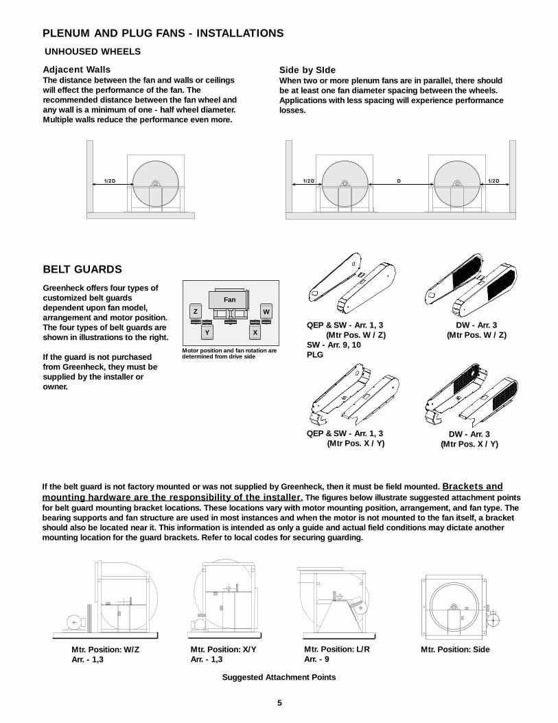
Adjacent WallsThe distance between the fan and walls or ceilingswill effect the performance of the fan. Therecommended distance between the fan wheel andany wall is a minimum of one - half wheel diameter.Multiple walls reduce the performance even more.
UNHOUSED WHEELS
Side by SIdeWhen two or more plenum fans are in parallel, there shouldbe at least one fan diameter spacing between the wheels.Applications with less spacing will experience performancelosses.
BELT GUARDS
Greenheck offers four types ofcustomized belt guardsdependent upon fan model,arrangement and motor position.The four types of belt guards areshown in illustrations to the right.
If the guard is not purchasedfrom Greenheck, they must besupplied by the installer orowner.
Fan
Z
Y X
W
Motor position and fan rotation are determined from drive side
5
1/2 D 1/2 D 1/2 DD
Mtr. Position: W/ZArr. - 1,3
Mtr. Position: L/RArr. - 9
Mtr. Position: X/YArr. - 1,3
If the belt guard is not factory mounted or was not supplied by Greenheck, then it must be field mounted. Brackets andmounting hardware are the responsibility of the installer. The figures below illustrate suggested attachment pointsfor belt guard mounting bracket locations. These locations vary with motor mounting position, arrangement, and fan type. Thebearing supports and fan structure are used in most instances and when the motor is not mounted to the fan itself, a bracketshould also be located near it. This information is intended as only a guide and actual field conditions may dictate anothermounting location for the guard brackets. Refer to local codes for securing guarding.
Suggested Attachment Points
Mtr. Position: Side
QEP & SW - Arr. 1, 3(Mtr Pos. W / Z)
SW - Arr. 9, 10PLG
DW - Arr. 3(Mtr Pos. W / Z)
QEP & SW - Arr. 1, 3(Mtr Pos. X / Y)
DW - Arr. 3(Mtr Pos. X / Y)
ROTATABLE HOUSINGSIt may be necessary to rotate the scroll of the fan to achieve a different discharge position than what was originally supplied.Centrifugal fans models BISW, AFSW (sizes 7 - 30, arr. 1, 4, 8, 9, and 10, class I and II) and Industrial Process fans (sizes 5 - 19,standard and heavy duty) have the flexibility to be rotated in the field. This is accomplished by removing the housing bolts,rotating the housing to a new discharge position, and reinstalling the bolts.
6
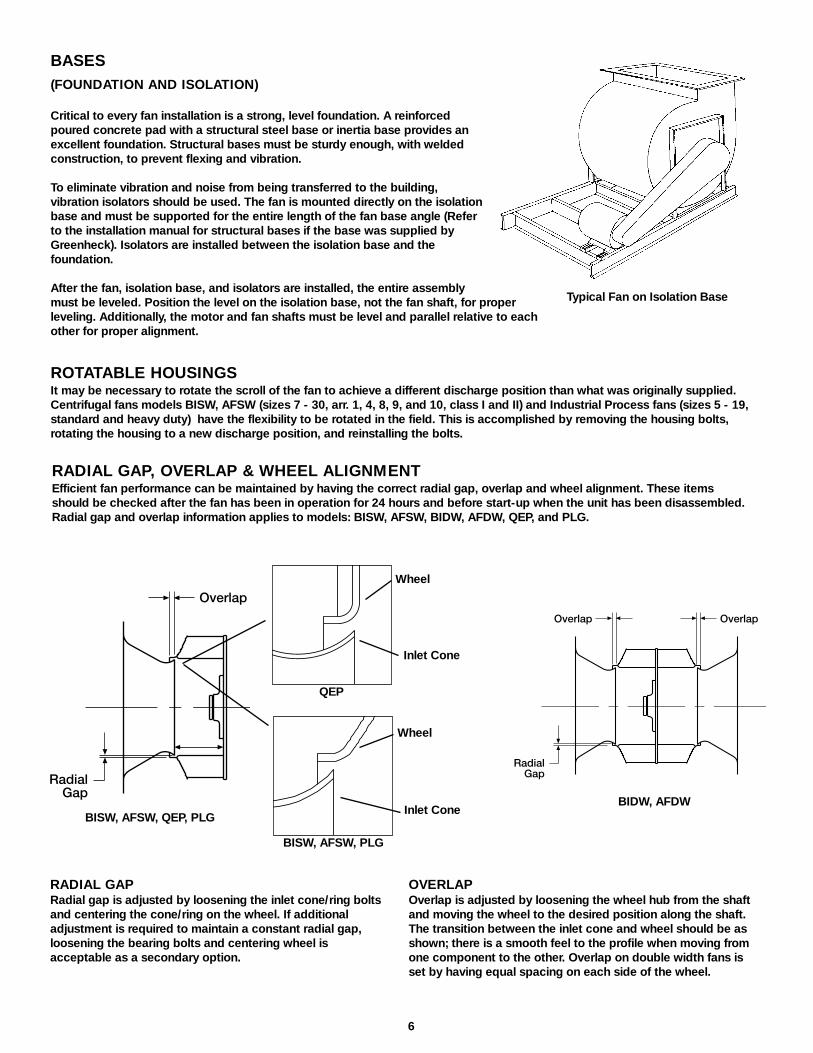
RADIAL GAPRadial gap is adjusted by loosening the inlet cone/ring boltsand centering the cone/ring on the wheel. If additionaladjustment is required to maintain a constant radial gap,loosening the bearing bolts and centering wheel isacceptable as a secondary option.
OVERLAPOverlap is adjusted by loosening the wheel hub from the shaftand moving the wheel to the desired position along the shaft.The transition between the inlet cone and wheel should be asshown; there is a smooth feel to the profile when moving fromone component to the other. Overlap on double width fans isset by having equal spacing on each side of the wheel.
BASES(FOUNDATION AND ISOLATION)
Critical to every fan installation is a strong, level foundation. A reinforcedpoured concrete pad with a structural steel base or inertia base provides anexcellent foundation. Structural bases must be sturdy enough, with weldedconstruction, to prevent flexing and vibration.
To eliminate vibration and noise from being transferred to the building,vibration isolators should be used. The fan is mounted directly on the isolationbase and must be supported for the entire length of the fan base angle (Referto the installation manual for structural bases if the base was supplied byGreenheck). Isolators are installed between the isolation base and thefoundation.
After the fan, isolation base, and isolators are installed, the entire assemblymust be leveled. Position the level on the isolation base, not the fan shaft, for properleveling. Additionally, the motor and fan shafts must be level and parallel relative to eachother for proper alignment.
Typical Fan on Isolation Base
RADIAL GAP, OVERLAP & WHEEL ALIGNMENTEfficient fan performance can be maintained by having the correct radial gap, overlap and wheel alignment. These itemsshould be checked after the fan has been in operation for 24 hours and before start-up when the unit has been disassembled.Radial gap and overlap information applies to models: BISW, AFSW, BIDW, AFDW, QEP, and PLG.
Overlap Overlap
RadialGapRadial
Gap
Overlap
BISW, AFSW, QEP, PLGBIDW, AFDW
BISW, AFSW, PLG
QEP
Inlet Cone
Wheel
Inlet Cone
Wheel

Improper Sheave Alignment Proper Sheave Alignment
7
V-BELT DRIVE INSTALLATION
1. Remove the protective coating from the end of the fan shaft and assure that it is free of nicks and burrs.
2. Check fan and motor shafts for parallel and angular alignment.
3. Slide sheaves on shafts - do not drive sheaves on as this may result in bearingdamage.
4. Align fan and motor sheaves with a straight-edge or string and tighten.
5. Place belts over sheaves. Do not pry or force belts, as this could result in damage tothe cords in the belts.
6. Adjust the tension until the belts appear snug. Run the unit for a few minutes (seesection on unit start-up) and allow the belts to "Set” properly.
7. With the fan off, adjust the belt tension by moving the motor base. (See belttensioning procedures in the maintenance section of this manual). When in operation,the tight side of the belts should be in a straight line from sheave to sheave with aslight bow on the slack side.
V-BELT DRIVESThe V-belt drive components, when supplied by Greenheck Fan Corporation, have been carefully selected for this units specificoperating condition. Caution: changing V-belt drive components could result in unsafe operating conditions which may causepersonal injury or failure of the following components: 1. Fan Shaft, 2. Fan Wheel, 3. Bearings, 4. V-belt, 5. Motor.
Aligning Sheaves with a Straight Edge
WHEEL ALIGNMENT CONTINUED
Correct wheel alignment for an industrial process fan (model IPA, IPO, or IPW) is achievedby centering the wheel in the housing.
FLEXIBLE COUPLINGS (ARR. 8 ONLY)Check for misalignment between the coupling halves. Parallel and angular misalignmentand separation gap are illustrated below. Refer to specific manufacturer’s installationinstructions for allowable misalignment and separation gap tolerances. When correctingfor misalignment using shims, the shims should only be located under the motor. Do notplace shims under the shaft bearings.
After aligning procedure, check for tightness of all coupling component pieces and ensurethat they are clean from dirt and debris.
Housing
Equal Spacing
Wheel
IPA, IPO, IPW
Parallel Misalignment Angular Misalignment Separation Gap

ADDITIONAL STEPS FOR INITIAL START-UP
1. Check for proper wheel rotation by momentarily energizing the fan. Rotation is always determined by viewing the wheel fromthe drive side and should correspond to the rotation decal affixed to the unit. One of the most frequently encounteredproblems with Centrifugal Fans is motors which are wired to run in the wrong direction. This is especially true with 3-phaseinstallations where the motor will run in either direction, depending on how it has been wired. To reverse rotation of a 3-phasemotor, interchange any two of the three electrical leads. Single phase motors can be reversed by changing internalconnections as described on the motor label or wiring diagram.
2. If the fan has inlet vanes, they should be partially closed to reduce power requirements. This is especially important if the fanis designed for a high temperature application and is being started at room temperature.
3. Fans with multi-speed motors should be checked on low speed during initial start-up.
4. Check for unusual noise, vibration or overheating of bearings. Refer to the "Troubleshooting" section of this manual if aproblem develops.
5. Grease may be forced out of the bearing seals during initial start-up. This is a normal self-purging feature of this type ofbearing.
8
UNIT START UP1. Disconnect and lock-out all power switches to fan. See warning below.2. Check all fasteners, set screws and locking collars on the fan, bearings, drive, motor base and accessories for tightness.3. Rotate the fan wheel by hand and assure no parts are rubbing.4. Check for bearing alignment and lubrication.5. Check for coupling alignment (Arr. 8 only).6. Check the V-belt drive for proper alignment and tension.7. Check the all guarding (if supplied) for being securely attached and not interfering with rotating parts.8. Check operation of variable inlet vanes or discharge dampers (if supplied) for freedom of movement.9. Check all electrical connections for proper attachment.
10. Check housing and ductwork, if accessible, for obstructions and foreign material that may damage the fan wheel.
WARNINGDisconnect and secure to the "Off" position all electrical power to the fan prior to inspection or servicing. Failure tocomply with this safety precaution could result in serious injury or death.
CW ROTATION
CentrifugalBackward Inclined
Industrial ProcessRadial Blade
CentrifugalAirfoil
Always viewed from the drive side.

Generally, fan vibration and noise is transmitted to other parts of the building by the ductwork. To eliminate this undesirableeffect, the use of heavy canvas connectors is recommended. If fireproof material is required, Flexweave 1000 - type FN-30 canbe used.
VIBRATIONExcessive vibration is the most frequentproblem experienced during initial start-up.Left unchecked, excessive vibration can causea multitude of problems, including structuraland/or component failure. The most commonsources of vibration are listed below.
Many of these conditions can be discoveredby careful observation. Refer to the trouble-shooting section of this manual for correctiveactions. If observation cannot locate the sourceof vibration, a qualified technician using vibrationanalysis equipment should be consulted. If theproblem is wheel unbalance, in-place balancingcan be done providing there is access to the fanwheel. Any correction weights added to the wheelshould be welded to either the wheel back(single-plane balance) or to the wheel back andwheel cone (two-plane balance).
Greenheck performs a vibration test on all centrifugal fansbefore shipping. Three vibration readings are taken on eachbearing in the horizontal, vertical, and axial directions. Theallowable maximum vibration for belt drive units is 0.15in/sec. peak (0.08 in/sec. direct drive) velocity filter-in at thefan rpm per AMCA standard 204. These vibrationsignatures are a permanent record of how the fan left thefactory and are available upon request.
1. Wheel Unbalance2. Drive Pulley Misalignment3. Incorrect Belt Tension4. Bearing / Coupling Misalignment5. Mechanical Looseness6. Faulty Belts7. Drive Component Unbalance8. Poor Inlet/Outlet Conditions9. Foundation Stiffness
CAUTION:When operating conditions of the fan are tobe changed (speed, pressure, temperature,etc.) consult Greenheck to determine if theunit can operate safely at the newconditions.
9
Once the unit has been put into operation, a routine maintenance schedule should be set up to accomplish the following:
1. Lubrication of bearings and motor.
2. Variable inlet vanes should be checked for freedom of operation and wear.
3. Wheel, housing, bolts and set screws on the entire fan should be checked for tightness.
4. Any dirt accumulation on the wheel or in the housing should be removed to prevent unbalance and possible damage.
5. Isolation bases should be checked for freedom of movement and the bolts for tightness. Springs should be checked for breaks and fatigue. Rubber isolators should be checked for deterioration.
6. Inspect fan impeller and housing looking for fatigue, corrosion, or wear.
When performing any service to the fan, disconnect the electrical supply and secure fan impeller.
MOTORSMotor maintenance is generally limited to cleaning and lubrication. Cleaning should be limited to exterior surfaces only.Removing dust and grease build up on the motor housing assists proper motor cooling. Never wash-down motor with highpressure spray. Greasing of motors is only intended when fittings are provided. Many fractional motors are permanentlylubricated for life and require no further lubrication. Motors supplied with grease fittings should be greased in accordance withthe manufacturer's recommendations. When motor ambient temperature does not exceed 104°F (40°C), the grease should bereplaced after 2000 hours of running time.
ROUTINE MAINTENANCE

Belt Span
Deflection = Belt Span64 The proper tension for operating a V-belt drive is the
lowest tension at which the belts will not slip at peakload conditions. For initial tensioning, the proper beltdeflection halfway between sheave centers is 1/64 in.for each inch of belt span. For example, if the beltspan is 64 inches, the belt deflection should be 1 inchusing moderate thumb pressure at mid-point of thedrive. Check belt tension two times during thefirst 24 hours of operation and periodically thereafter.
V-BELT DRIVESV-belt drives must be checked on a regular basis for wear, tension, alignment and dirt accumulation. Premature or frequent beltfailures can be caused by improper belt tension, (either too loose or too tight) or misaligned sheaves. Abnormally high belttension or drive misalignment will cause excessive bearing loads and may result in failure of the fan and/or motor bearings.Conversely, loose belts will cause squealing on start-up, excessive belt flutter, slippage, and overheated sheaves. Eitherexcessively loose or tight belts may cause fan vibration.
When replacing V-belts on multiple groove drives all belts should be changed to provide uniform drive loading. Do not pry beltson or off the sheave. Loosen belt tension until belts can be removed by simply lifting the belts off the sheaves. After replacingbelts, insure that slack in each belt is on the same side of the drive. Belt dressing should never be used.
Do not install new belts on worn sheaves. If the sheaves have grooves worn in them, they must be replaced before new beltsare installed.
10
SHAFT BEARINGSThe bearings for Greenheck fans are carefully selected to match the maximum load and operating conditions of the specificclass, arrangement, and fan size. The instructions provided in this manual and those provided by the bearing manufacturer, willminimize any bearing problems. Bearings are the most critical moving part of the fan, therefore special care is required whenmounting them on the unit and maintaining them.
Refer to the following chart and the manufacturers instructions for grease types and intervals for various operating conditions.Never mix greases made with different bases. This will cause a breakdown of the grease and possible failure of the bearing.
* Suggested initial greasing interval is based on 12 hour per day operation and 150 degree F. maximum housing temperature. For continuous (24 hour) operation, decrease greasing interval by 50%.
- If possible relubricate with grease while in operation, without endangering personnel.- For ball bearings (operating) relubricate until clean grease is seen purging at the seals. Be careful not to
unseat the seal by over lubricating.- For ball bearings (idle) add 1-2 shots of grease up to 2 inch bore sizes, and 4-5 shots of grease above 2 inch
bore sizes with hand grease gun.- For roller bearings relubricate with 4 shots of grease up to 2 inch bore size, 8 shots for 2 inch - 5 inch bore
size, and 16 shots above 5 inch bore size with hand grease gun.- Adjust lubrication frequency based on condition of purged grease. - A high quality lithium base grease conforming to NLGI Grade 2 consistency, such as those listed below,
should be used.
MOBILITH SHC 220 TEXACO MULTIFAK AFB2 SHELL ALVANIA #2MOBILITH AW2 TEXACO PREMIUM RB EXXON UNIREX N2
WARNING: Lubricate bearings prior to periods of extended shutdowns or storage and rotate shaft monthly to aid in preventing corrosion. If the fan is stored more than three months, the bearings should bepurged with new grease prior to start-up.
Recommended Bearing Lubrication Schedule for Greenheck FansRelubrication Schedule in Months*
Bearing Bore (inches)Fan1/2 - 1 1/8 - 1 5/8 - 1 15/16 - 2 7/16 - 3 3/16 - 3 15/16 - 4 15/16 -
RPM 1 1 1/2 1 7/8 2 3/16 3 3 1/2 4 1/2 5 1/2To 250 6 6 6 6 6 5 4 3
500 6 6 6 5 4 3 3 2750 6 5 4 3 3 2 2 11000 6 4 3 2 2 1 1 0.51250 5 3 2 1 1 0.5 0.5 0.251500 5 2 1 1 0.5 0.5 0.25 0.252000 5 1 1 0.5 0.25 0.25 0.25 0.252500 4 0.5 0.5 0.25 0.25 0.253000 4 0.5 0.25 0.25 0.254000 3 0.25 0.25 0.25 0.255000 2 0.25 0.25 0.25

TROUBLESHOOTINGProblem Cause Corrective Action
Wheel Rubbing Inlet Adjust wheel and/or inlet cone. Tighten wheel hub or bearing collars on shaft.
V-Belt DriveTighten sheaves on motor/fan shaft. Adjust
Excessivebelt tension. Align sheaves properly (see page 7).Replace worn belts or sheaves.
Noise
BearingsReplace defective bearing(s). Lubricate bearings.Tighten collars and fasteners.
Wheel UnbalanceClean all dirt off wheel. Check wheel balance,rebalance in-place if necessary.
Low CFMFan Check wheel for correct rotation. Increase fan speed.*
Duct System See page 3.
High CFMFan Decrease fan speed.
Duct system Resize ductwork. Access door, filters, grills not installed.
Static PressureDuct system has more Change obstructions in system. Use correction factor to
Wrong or less restriction adjust for temperature/altitude. Resize ductwork.than anticipated Clean filters/coils. Change fan speed.*
High HorsepowerFan Check rotation of wheel. Reduce fan speed.
Duct System Resize ductwork. Check proper operation of face andbypass dampers. Check filters and access doors.
Electrical Supply Check fuses/circuit breakers. Check for switches turnedoff or disconnected. Check for correct supply voltage.
Fan Doesn't Drive Check for broken belts. Tighten loose pulleys.Operate
MotorAssure motor is correct horsepower and not trippingoverload protector.
Overheated ShaftLubrication Check for excessive or insufficient grease in the bearing.
Bearing Replace damaged bearing. Relieve excessiveMechanicalbelt tension. Align bearings. Check for bent shaft.
Belts Adjust tightness of belts. Replacement belts should be aExcessive matched set.Vibration
Check alignment of shaft, motor and pulleys. Adjustable System Unbalance pitch pulleys with motors over 15 hp motors are especially
prone to unbalance. Check wheel balance, rebalance if necessary.
Check alignment between coupling, motor and fan shafts. Coupling Misalignment Any adjustments should be made per coupling
manufacturer’s instructions. Shim only under motor.
* AIways check motor amps and compare to nameplate rating. Excessive fan speed may overload the motor and result inmotor failure. Do not exceed the maximum cataloged rpm of of the fan.
NOTE: Always provide the unit model and serial numbers when requesting parts or service information.
11
GREENHECK P.O. BOX 410 SCHOFIELD, WISCONSIN 54476-0410
PH. 715-359-6171www.greenheck.com
WARRANTYGreenheck warrants this equipment to be free from defects in material and workmanship for period of one year from thepurchase date. This warranty limits our responsibility to repairing or replacing, to the original purchaser, any part or partsof said equipment found to be defective upon examination by representatives of Greenheck. Additionally, said part orparts will be returned to and received by the factory only after prior authorization, with transportation charges prepaid.
Greenheck shall not be obligated under this warranty, for payment of any delivery, removal or installation charges withregard to repair or replacement of any defective part or parts.
Motors are warranted by the motor manufacturer for a period of one year. Should motors furnished by Greenheck provedefective during this period, they should be returned to the nearest authorized motor service station.
PN 463687 Cent. IOM FSRev. 2 March 2004
Copyright © Greenheck Fan Corp. 2004
12
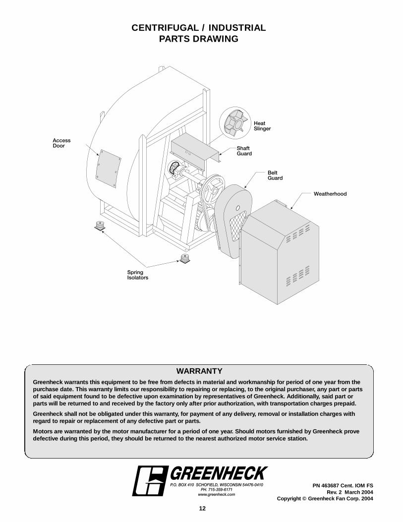
HeatSlinger
BeltGuard
Weatherhood
AccessDoor
SpringIsolators
ShaftGuard
CENTRIFUGAL / INDUSTRIALPARTS DRAWING