installation, operation and maintenance - hidrostal linea-3... · ll8f0004_e. instruction manual....
TRANSCRIPT
LL8F0004_E
INSTRUCTION MANUALINSTALLATION, OPERATION AND MAINTENANCE
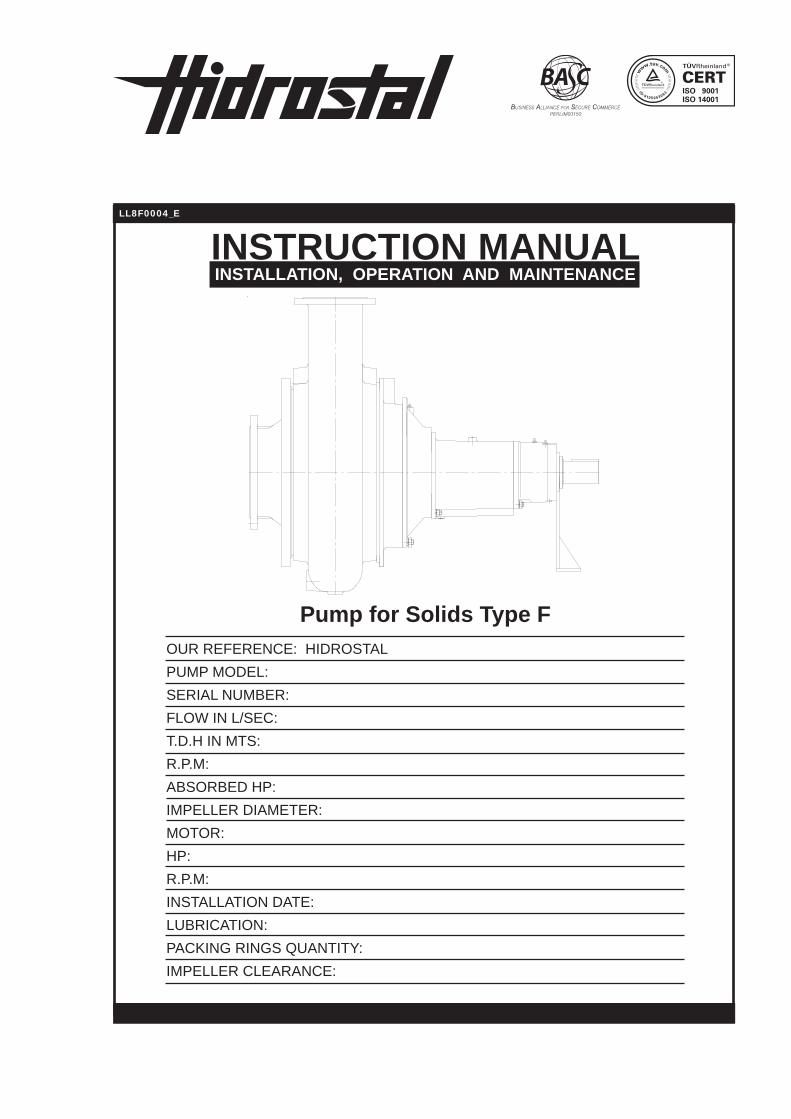
Pump for Solids Type FOUR REFERENCE: HIDROSTALPUMP MODEL: SERIAL NUMBER: FLOW IN L/SEC: T.D.H IN MTS: R.P.M: ABSORBED HP: IMPELLER DIAMETER: MOTOR: HP: R.P.M: INSTALLATION DATE: LUBRICATION: PACKING RINGS QUANTITY: IMPELLER CLEARANCE:

MANUAL PUMP FOR SOLIDS TYPE “F”LÍNEA III - VERSIÓN: E - CÓDIGO: LL8F0004 - 03-2015
2
INDEX
1. GENERAL INFORMATION........................ 4 1.1 Description....................................... 4 1.1.1 Casing........................................ 4 1.1.2 Impeller...................................... 4 1.1.3 Wear Rings................................ 4 1.1.4 Shaft........................................... 4 1.1.5 Bearing Frame........................... 4 1.1.6 StuffingBox............................... 4 1.2 Installation....................................... 4 1.2.1 Foundation................................. 5 1.2.2 Alignments................................. 5 1.2.3 Leveling...................................... 5 1.2.4.1FlexibleDiskCoupling.......... 6 1.2.4.2 Cardan joint.......................... 6 1.2.4.3 Belt Transmission................. 6 1.2.5 Foundation Finishing.................. 6 1.2.6 Suction....................................... 6 1.2.7 Discharge................................... 7 1.2.8 Sealing System.......................... 8 1.2.9 Service Connection..................... 8 1.2.10 Instrumentation........................ 9 1.2.11 FinalVerification...................... 9 1.3 Starting............................................. 9 1.3.1 Priming........................................ 9 1.3.1.1 Positive Suction Pumps........ 9 1.3.1.2 Negative Suction Pumps...... 10 1.3.2 Rotation...................................... 10 1.3.3 StuffingBox................................ 10 1.3.4 Starting....................................... 10 1.3.5 Stopping..................................... 10 1.3.6 InitialandPeriodicalChecking... 10 1.3.7 Service Characteristic................ 11 1.3.8 N.P.H.S (Net Positive Suction Head)......................................... 11 1.3.9 CorrosionandAbrasion............. 11 1.4 Periodical Maintenance.................... 11 1.4.1 Lubrication................................. 11 1.4.2 LabyrinthSeal............................ 11 1.4.3 Sealing Shaft Syste.................... 12 1.4.4 StuffingBoxPackingReplace.. 12
1.4.5 Impeller Clearance................... 14 1.4.6 Failure Caus............................. 15 1.5 Recycling and end of product life:
MANUAL PUMP FOR SOLIDS TYPE “F”LÍNEA III - VERSIÓN: E - CÓDIGO: LL8F0004 - 03-2015
3
“F” TYPE PUMP
20820
6
424
401
402
408
214
167
166
415
165
203
218A
423
411
200
406
408A
417
218
400
112
410
216
204
209
419
106
134
215
201
141
202
102
101
118
134
121
100
213
144
126
119
154
110
131
149
221
146
229
210
220
131
132
104
129
161
147
157
135
130
109
127
114

MANUAL PUMP FOR SOLIDS TYPE “F”LÍNEA III - VERSIÓN: E - CÓDIGO: LL8F0004 - 03-2015
4
1 GENERAL INFORMATIONIntroductionYouhaveacquireda valuable equipment. PayattentionandbecarefulwithyourHidrostalpumpinordertoobtainexcellentresults.
Yourpumphasbeendesignedandconstructedinorder to render years of constant service, as long astheuserstriclyfollowstheseinstructionsmustbefullyunderstoodbeforestartingthepump.
Identification PlateTranscribethedatafilledinthepumpidentificationplatetothismanualandmentionitwhenyoureferto us for any consultation.
WarrantyAsyoucannotice in the instructionsweofferawarranty over the pump according to our pur-chasegeneralconditions.Howeverthewarrantystops if the pump is used to pump other liquids, concentrations, temperatures and characteristics that differ from the ones indicated in our order acknowledgment, likewiseby failuresoriginatedbywrongmaintenance,inadequateuse,nonap-propriateservice,deficientemplacementorincor-rect installation
1.1 Description
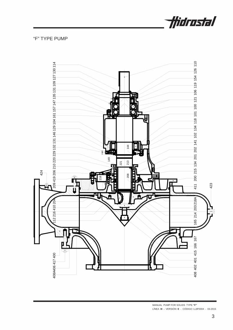
1.1.1 Casing (Part 400)Verticalsplitvolutecasingwithaxialsuction;radialdischargeandbackpulloutdesign,whichallowsafastbearingframeandimpellerservicewithoutdismantling any pipe fastened to the casing. If the pumpcouplingusedisaflexibleextendedtypeorcardantype.Themotorcanalsostandfixedtothebase.Thecasinghasbeenhydrostaticallytested.
1.1.2 Impeller (Part 401)Closed type impeller, its hydraulic design provides a gentle handing of the solids in suspension avoid-ing rough changes in direction and acceleration.The impeller is firmlymounted on the impellerflange fastened to the pump shaft by a centralbolt. This design allowsa quickmounting anddismantling of the impeller even in pumpswithmany years of running.
1.1.3 Wear Rings ( Part 408 )Thewearringhasbeendesignedtobeeasilyre-placed,allowingtomaintaintheoriginalefficiencywithalowmaintenancecost.
1.1.4 Shaft ( Part 110 )Carbon steel shaft C-1045 or stainless steelmountedongreaselubricatedbearings.Replace-ablestainlesssteelshaftsleevetoavoidanydam-ageduetothestuffingboxpackingfriction.
1.1.5 Bearing FrameWidelysizedbearingframe,backpulloutdesignallows the pump to be dismantledwithout theremoval of any pipe fastened to the casing. The grease lubricated bearing frame has been de-signedfora50,000hourofoperationrate,whenthepumprunsonitsbestefficiencypoint.
1.1.6 Stuffing BoxSplittedstuffingbox type,whichallowsaneasyaccesstothestuffingboxpackingforitsreplace-ment.Theexternalconnection(3)istoperformtheshaftsealinginthestuffingbox.Normallytheequipmentisprovidedbyfreeasbestospacking.
1.2 Installation The pump installation should allow the directconnectation of the suction and discharge pipe withtheiraccessories(valvesandfittings)prop-erly supported. The connection should be inanindependedwaytoavoidthetransmissionofany strength and tension to the pump. Pipe ten-sionsgenerallycausemisalignments,vibrations,couplingbreakingandwheelsdamage.Thepipeflangesbeforebeingadjustedwiththebolts.
Project the pipe so that a minimum of curves, el-bowsandaccessorieswouldbeused.Installthepipethenearestpossibletothewatersupplyortheliquidbeingheld.Rememberthatifthelengthof the pipe increases, the loss of capacity of the pumpbyfrictionincreasesaswell,thusthecostof the equipment operation.
Leaveenoughspaceintheinstallationtoallowaneasyaccessfortheinspectionjob,dismantlingandmaintenanceofthepumpandtheauxiliaryequip-ment. If the pumps are placed in pits, they must beprotectedagainstfloods.

MANUAL PUMP FOR SOLIDS TYPE “F”LÍNEA III - VERSIÓN: E - CÓDIGO: LL8F0004 - 03-2015
5
1.2.1 FoundationIt is great importance to mount the pumps on solid foundations,preferentlyonconcretebases.Itisnormallysatisfactorytobuildaconcretebaseus-inga1-3-5mix(cement,sand,andgravel)withathicknessaccordingtothebasementcharacteristicThefoundationanchorboltsshouldbefixedtotheconcreteasshowedin(Fig.1).The diameter of the pipe placed around the anchor foundationboltshouldexceedtwoorthreetimes
base,interlockingitwithathinwedgeinordertocountwithaconvenientspace. Theflexiblecouplingsshouldnotbeusedtocom-pensate the pump and motor shaft misalignment. The flexible coupling allowsonly absorbing themisalignmentproducedbytemperaturechanges.
thislast,allowingtheanchorfoundationbolttobefreelyremovedtoitsfinalposition.
1.2.2 AlignmentThe pumping units is correctly aligned in the fac-tory,however theexperiencehasdemonstratedthat flexing and bending could happen duringtransportation in spite of the tough construction of thebases,inconsequenceanalignmentre-checkis needed after the complete pump installation.
1.2.3 LevelingWhentheunitisreceivedwiththepumpandthemotor placed on their common base, this unitshouldbemountedonitsfoundationbase.Thecouplingsshouldbedisconnected,leavinga3/4”and 1.1/2” space between the top face of thefoundationblockandthebottomfaceofthepump
Fig. 1
Fig. 1
MANUAL PUMP FOR SOLIDS TYPE “F”LÍNEA III - VERSIÓN: E - CÓDIGO: LL8F0004 - 03-2015
6
1.2.4 Alignment
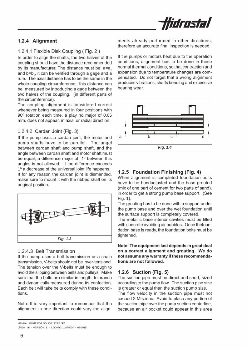
1.2.4.1FlexibleDiskCoupling(Fig.2)Inordertoaligntheshafts,thetwohalvesofthecoupling should have the distance recommended byitsmanufacturer.Thedistancemustbe:a=a1 andb=b1,itcanbeverifiedthroughagageandarule.Theaxialdistancehastobethesameinthewholecouplingcircumference;thisdistancecanbemeasuredbyintroducingagagebetweenthetwohalvesofthecoupling.(indifferentpartsofthe circumference).The coupling alignment is considered correct wheneverbeingmeasuredinfourpositionswith90º rotation each time, a play no major of 0.05 mm.doesnotappear,inaxialorradialdirection.
1.2.4.2 Cardan Joint (Fig. 3)If the pump uses a cardan joint, the motor and pump shafts have to be parallel. The angelbetween cardan shaft andpumpshaft, and theanglebetweencardanshaftandmotorshaftmustbeequal,adifferencemajorof1ºbetweenthisanglesisnotallowed.Itthedifferenceexceeds1º a decrease of the universal joint life happens.If for any reason the cardan joint is dismantled, makesuretomountitwiththeribbedshaftonitsoriginal position.
1.2.4.3 Belt TransmissionIf thepumpusesabelt transmissionorachaintransmission,V-beltsshouldnotbeover-tensiond.ThetensionovertheV-beltsmustbeenoughtoavoidtheslippingbetweenbeltsandpulleys.Makesurethatthebeltsaresimilarinlength,toleranceand dynamically measured during its confection. Eachbeltwilltakebeltscomplywiththesecondi-tions.
Note: It is very important to remember that thealignment in one direction could vary the align-
ments already performed in other directions, thereforeanaccuratefinalinspectionisneeded.
If the pumps or motors heat due to the operation conditions, alignment has to be done in thesenormal thermal conditions, so that contraction and expansionduetotemperaturechangesarecom-pensated.Donotforgetthatawrongalignmentproducesvibrations,shaftsbendingandexcessivebearingwear.
Fig. 1.4
1.2.5 Foundation Finishing (Fig. 4)When alignment is completed foundation boltshave tobehandadjustedand thebasegrouted(mixofonepartofcementfortwopartsofsand),inordertogetastrongpumpbasesupport.(SeeFig. 1).Thegroutinghastobedonewithasupportunderthepumpbaseandoverthewetfoundationuntilthe surface support is completely covered. Themetallicbaseinteriorcavitiesmustbefilledwithconcreteavoidingairbubbles.Oncethefoun-dationbaseisready,thefoundationboltsmustbetightened.
Note: The equipment last depends in great deal on a correct alignment and grouting. We do not assume any warranty if these recommenda-tions are not followed.
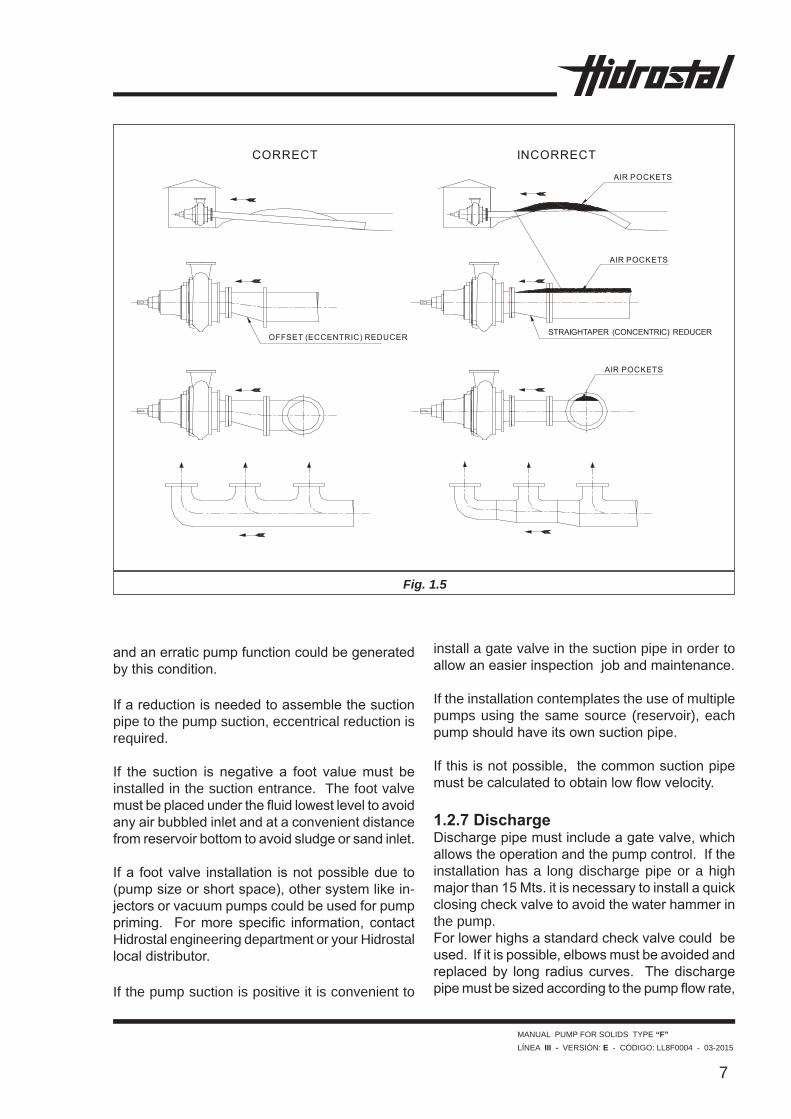
1.2.6 Suction (Fig. 5)Thesuctionpipemustbedirectandshort,sizedaccordingtothepumpflow.Thesuctionpipesizeis greater or equal than the suction pump size.The flow velocity in the suction pipemust notexceed2Mts./sec.Avoidtoplaceanyportionofthe suction pipe over the pump suction centerline, becauseanairpocketcouldappearinthisarea
Fig. 1.3
MANUAL PUMP FOR SOLIDS TYPE “F”LÍNEA III - VERSIÓN: E - CÓDIGO: LL8F0004 - 03-2015
7
andanerraticpumpfunctioncouldbegeneratedbythiscondition.
Ifareductionisneededtoassemblethesuctionpipe to the pump suction, eccentrical reduction is required. If the suction is negative a foot valuemust beinstalled in the suction entrance. The foot valve mustbeplacedunderthefluidlowestleveltoavoidanyairbubbledinletandataconvenientdistancefromreservoirbottomtoavoidsludgeorsandinlet. Ifa footvalve installation isnotpossibledue to(pumpsizeorshortspace),othersystemlikein-jectorsorvacuumpumpscouldbeusedforpumppriming. Formore specific information, contactHidrostal engineering department or your Hidrostal localdistributor. If the pump suction is positive it is convenient to
install a gate valve in the suction pipe in order to allowaneasierinspectionjobandmaintenance.
If the installation contemplates the use of multiple pumps using the same source (reservoir), each pumpshouldhaveitsownsuctionpipe. Ifthisisnotpossible,thecommonsuctionpipemustbecalculatedtoobtainlowflowvelocity.
1.2.7 Discharge Dischargepipemustincludeagatevalve,whichallowstheoperationandthepumpcontrol.Iftheinstallation has a long discharge pipe or a high majorthan15Mts.itisnecessarytoinstallaquickclosingcheckvalvetoavoidthewaterhammerinthe pump.Forlowerhighsastandardcheckvalvecouldbeused.Ifitispossible,elbowsmustbeavoidedandreplacedby long radiuscurves. Thedischargepipemustbesizedaccordingtothepumpflowrate,
Fig. 1.5
MANUAL PUMP FOR SOLIDS TYPE “F”LÍNEA III - VERSIÓN: E - CÓDIGO: LL8F0004 - 03-2015
8
avoidinganyflowvelocityover3Mts./sec.Thepumpdischargesizemustnotbeaconditionalforpipedischargesizing.Remembertopreventtheconnection for pump priming. Sometimesitisconvenienttoinstallanexpansionjoint to avoid the transmission of any discharge pipestressoverthepump.(Duetothermalex-pansion, piping misalignment or due to any other reason).
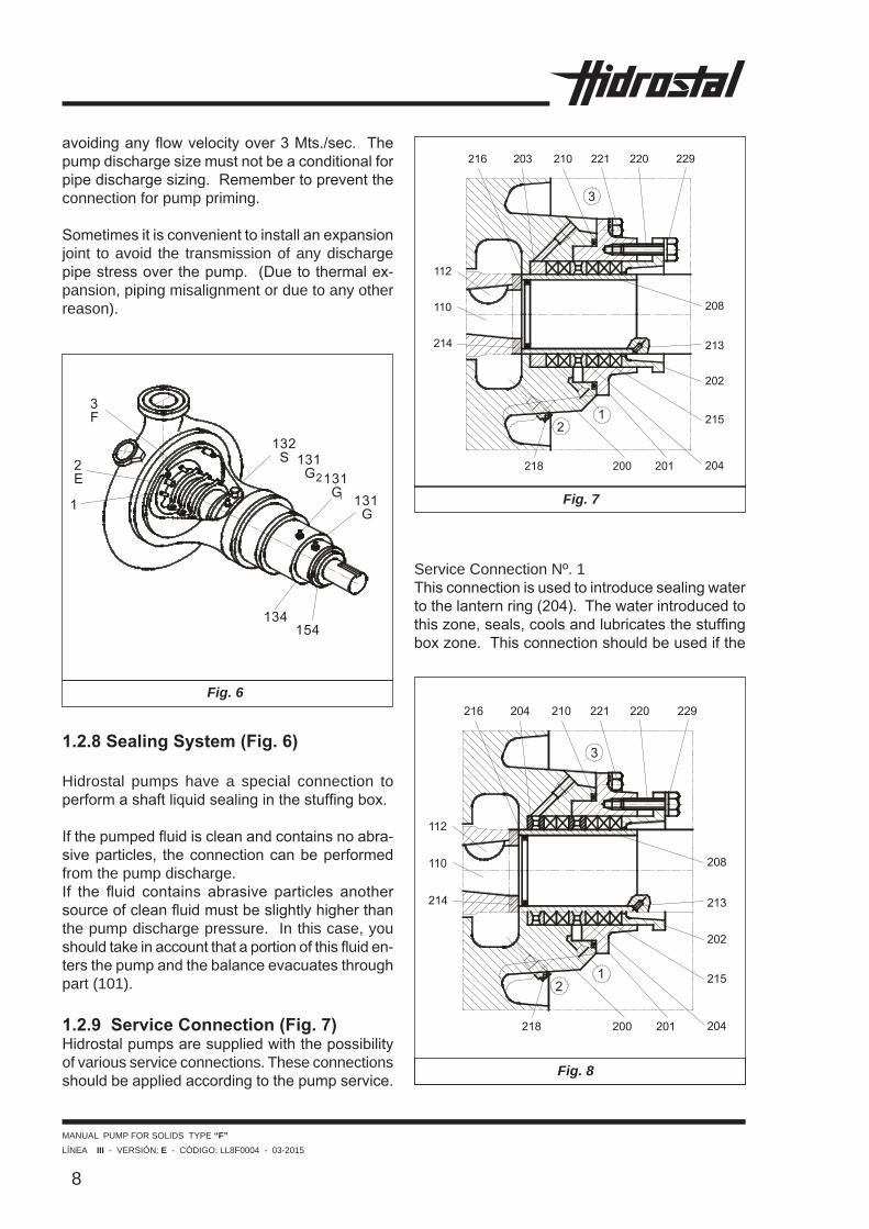
Service Connection Nº. 1Thisconnectionisusedtointroducesealingwatertothelanternring(204).Thewaterintroducedtothiszone,seals,coolsandlubricatesthestuffingboxzone.Thisconnectionshouldbeusedifthe
Fig. 6
Fig. 7
1.2.8 Sealing System (Fig. 6) Hidrostal pumps have a special connection to performashaftliquidsealinginthestuffingbox. Ifthepumpedfluidiscleanandcontainsnoabra-siveparticles, theconnectioncanbeperformedfrom the pump discharge. If the fluid contains abrasive particles anothersourceofcleanfluidmustbeslightlyhigherthanthe pump discharge pressure. In this case, you shouldtakeinaccountthataportionofthisfluiden-tersthepumpandthebalanceevacuatesthroughpart (101).
1.2.9 Service Connection (Fig. 7)Hidrostalpumpsaresuppliedwiththepossibilityof various service connections. These connections shouldbeappliedaccordingtothepumpservice.
Fig. 8

MANUAL PUMP FOR SOLIDS TYPE “F”LÍNEA III - VERSIÓN: E - CÓDIGO: LL8F0004 - 03-2015
9
Fig. 9
fluidtobepumpedissewagewaterorwaterwithsolids in suspension (Fig. 7). Ifthefluidtobepumpedcontainssmallquantitiesofsolids, thisconnectioncouldbe relacedbyagrease cup in order to introduce grease once in a whiletokeepthestuffingboxpackinglubricated.UseyellowgreaseALVANIANº.3(Shell),MOBIL-LUXM-2(Mobiloil)oritsequivalent.
Service Connection Nº 2 (E)Usedtointroducewaterinsidethechamberformedbythebackpartoftheimpeller(401)andthebackcover (200), in order to Clean solids accumulations in this area.Normallysolidsaccumulatiosoccurwhentheliquidtobepumpedcontainshighsolidsconcentrationswithdehydrationtendency.Thisserviceconnec-tionusesasolenoidvalvewitha timer to injectthewaterduring60seconds from time to time.Thiswaterinjectionmustbedoneasfrequentasneeded.Inverticalpumpsthisconnectioncouldbeusedtoevacuate the air accumulated in this area, espe-ciallywhenthefluidtobepumpedhasatendenceto gasify.
Service Connection Nº 3 (F)Thisisnotastandardconection.Itisusedwhen
abrasive liquidsor liquidswithacrystallize ten-dencyarepumped.Thisconnectioncanbedonereplacing the lastpackingring (205)byanotherlantern ring (204) Fig. 8. Sometimes the lantern ring position change is enough,dependingonthepumpedfluidcharac-teristic (204) Fig. 9.Thewaterintroducedtothisconnectiongoesdi-rectly to the shaft sleeve surface (208), near the impeller,avoidingthe inletofabrasivematerialsandlubricatingthestuffingbox.
1.2.10 InstrumentationTo verify the functioning and the pump running conditions, a vacuumpressure gage in the suction andapressuregageinthedischargeshouldbeconnected.Thepressuregageshavetobemountedinacon-venientplaceforeasychecking.Ashutoffdevicemustbeplacedbeforethepressuregauge.Ifthepumpisdrivenbyanelectricalmotor,voltmeter,ampmeterandprotectionelementsmustbeplacedintheswitchboard.
1.2.11 Final verificationWhenthepipeinstallationisfinished,checkthealignmentonemoretime;proceedaccordingtotherulerandgagemethodabovementioned.After the stuffing box adjusting and alignmentchecking,thepumpshaftshouldbehandrotated(free and soft rotation).
1.3 Starting
1.3.1 PrimingPrimingshoulbedonebeforestartingthepump,thesuctionpipesandthecasingwillbefilledwithliquid.Rememberthataprolongedfunctioningofthepumpwithoutliquid,producesseriousdamagetotheshaftorstuffingbox.
1.3.1.1 Positive Suction PumpsClose the discharge valve and open the suction valvesothattheliquidfillsthepump.Openthedrain valve or drain plug located on the top of the pump and release air until the pump is completely filledwiththeliquidandairfree.Finallyclosethedrainvalveorscrewthedrainplug(424). 1.3.1.2 Negative Suction Pumps
MANUAL PUMP FOR SOLIDS TYPE “F”LÍNEA III - VERSIÓN: E - CÓDIGO: LL8F0004 - 03-2015
10
Close the discharge valve, open the priming con-nectionandfillthepumpcasingcompletely(drainplug)(424).Oncethepumpisprimed,wait5min-utesobservingtheliquidlevelinsidethepump,thelevel should not vary. If the level tends to diminish, proceedwiththefootvalverevisionandrepairitif necessary.
1.3.2 RotationThe pump should rotate in the direction indicated bythearrowinthecasing.Therotationisinclock-wisedirection,observingthepumpfromthedriverside. 1.3.3 Stuffing BoxInthepumpssuppliedwithstuffingbox,thepack-ingmaterialhasbeenselectedtoadeterminateapplication. Prior to the pump starting, verify thepackingconditions,removingthestuffingboxgland (202) (Figs. 7, 8 and 9). If the pump is not goingtobeusedwithinthefirst60daysafteritsdispatch,apackinginspectionisneeded.Iftheperiodofdisuseislonger,thepackingshouldbecheckedandreplacedwhenitslubricantproper-ties are lost or dryness occurs. In all cases it is important to remember to inspect the packingsbeforepumpstarting.Drynessinpackingsisthemaincauseofexces-sive leakageandeventually the causeof shaftsleevedamages(208).Anextratorqueisneededinthepackingboltsinordertoavoidanexcessiveleakage.Oncethepackingsconditionshavebeenverified,start the pump as indicated in (1.3.4.) and adjust thestuffingboxasfollows:
1. Make sure that the bolts in the stuffing boxglandarehandadjusted.Inthefirst10min.ofoperation,plentyfiltrationshouldappear.
2. Adjust carefully the stuffing box gland bolts(202) half turn every 10 min. until the spurt turnsintoaconstantdropping,approximately20 drops/min.
3. Thestuffingboxconditionshouldbeperiodicallyverifiedduringthefirstweekofoperationandbeadjustedupto20drops/min.
1.3.4 StartingOpentheadmissionanddischargevalves.Checkif the pump rotates hand free. Start the electrical
motorandcheckthecurrentwithanammeterinorder to avoid any overcharge.
In the case that the pressure does not increase after pump start, it is a sign that air remains in the suction. In such case, stop the pump immediately and prime the pump again.Thepumpoperationwithoutwaterisharmfulandcould damage the pump in a short time. 1.3.5 StoppingIftheinstallationhasawaterhammerpreventionvalve or if its T.D.H. is no major than 15 Mts., the detention of the motor is enough. In installations wheretheT.D.H.ismajorthantheindicated,pro-ceedwiththepartialclosingofthedischargevalve,beforethepumpstopping.Thisisnecessarytoavoid the reverse rotation of the pump.
In automatic installations, if the detention is pro-ducedbyelectricalenergyfailures,anewmanualstarting is needed.
1.3.6 Initial and Periodical Checking 1. Thepumpstartingshouldbesoftandvibrations
free.2. Check the bearings temperature.Normally
thetemperaturemustbeconstant(maximun70º).Ifthetemperaturestartstorise,checkthebearingsimmediately.
3. Checkthestuffingboxforleakingaccordingtopoint 2 of 1.3.3 and for any overheating sign.
4. When an external source for sealing refrig-eration is needed, check that thedifferencebetweenrefrigerationwatertemperatureoftheoutlet side and the inlet side is no major than 10ºC.
5. Avoid any pump or motor overcharge.6. Whenthepumpworkswithnegativesuction,
checkthattheNPSHavailableintheinstalla-tionismajorthantheNPSHrequiredbythepump.Thereservoirmustbealwaysfullandfreeofmaterials thatcouldcausepumpob-struction.
7. TheT.D.H.specifiedinthequotationmustnotdiffer the installation T.D.H. In that case pump failure could occur.
8. Whenastand-bypumpisavailable,itiscon-venienttouseitinanalternateway.

MANUAL PUMP FOR SOLIDS TYPE “F”LÍNEA III - VERSIÓN: E - CÓDIGO: LL8F0004 - 03-2015
11
1.3.7 Service CharacteristicTheHidrostalpumphasbeendesignedtooper-atewith a determinate speed,T.D.H. and flow,according to the given information. If the T.D.H. is different than the one indicated in he order, a mo-toroverchargingcouldoccur.Itisnecessarytofixthisconditioninordertoobtainagoodequipmentoperation. Due to its special design the solids han-dlingHidrostalpumpscannotbethrottledtoreducethe motor charge as standard centrifugal pumps.Toreducethemotoroverchargeanewimpellermustbeplacedinthepumpaccordingtothenewhydraulic conditions. In any case consult our engineering department or your nearest Hidrostal localdistributor.
1.3.8 NPSH (Net Positive Suction Head)
If thepumpdoesnot complywith the specifiedflowrate,avariationintheNPSHavailablecouldbeattributedtothiscondition.EachpumphasitsownNPSHrequirementcurveasshowedinthecharacteristics pump curves. If the NPSH avail-ableislessthantheNPSHrequiredbythepump,the pump is cavitating. Pump cavitation generates noises,vibrations,motoroverchargeandflowratedecrease). The liquid temperature and the altitude of the installationalsoaffecttheNPSHavailable.(Re-memberthattheatmospherepressurevarieswiththe altitude). An accurate calculation of NPSH availablemustbedonewhentheseconditionsap-pear.Iftheliquidtobepumpedhasatendencetogasify a positve suction pump is required.
1.3.9 Corrosion and abrasion
Whenthefluidtobepumpedhasabrasiveorcor-rosive properties a correct pump material selection mustbedone. In thiswaycostlypumpfailurescouldbeavoided.Ifthefluidtobepumpediscor-rosiveorabrasiveyoumustcontactourengineer-ingdepartmentoryourHidrostallocaldistributor.
1.4 Periodical Maintenance
1.4.1 Lubrication
Thebearingsmustberegularly lubricated.Usegoodqualitylithiumsoapgrease,waterresistantandappropriateforservicetemperaturesbetween-25ºC and 110ºC. Apply only the necessary amount of grease (0.025 kg. per bearing). Excessivegreaseapplicationcouldcausebearingoverheatingandfailures.Usemulti-purposegreaseShellAlvaniaEP-2,MobiloilMultiplex48orequivalents.
Thebearingstemperaturemeasuredinthebear-ingframeexternalsideshouldnotexceed70ºC.
ProcedureBefore lubricating, establish the discharge ofgrease amount of your gun grease per each shoot-ingasfollows:
1. Weight thegreaseamountobtainedafter10shootings.
2. Calculatetheweightingramspereachshoot-ingandmarkthisdataonyourgungrease.
Proceedtolubricateasfollows:a) Remove 134 and 154 plugs and start the pump
for at least 10 minutes in order to evacuate the oldremaininggreasefromtheequipmentbybearingheating.(Fig.1.7)
b) Setback134and154plugs.c) Cleanupthelubricatingpoints(G,G1andG2).
Note:BearingframeE2Sdoesnothavelubricat-ing point G.d) The necessary grease amount in grams must
be injected ineach lubricatingpointas indi-catedinthetable1.4.1.2.
1.4.2 Labyrinth sealThepumpssealedwithstuffingboxhavealaby-rinthsealinordertoavoidwaterinlettothebear-ings.Thissealmustbelubricatedbyagreasecup(132),usingthesamebearinggreaseaccordingtothestuffingboxconditions.Thegreasecupmustbeadjusteduntilthegreaseappearsthroughthelabyrinthseal.(Fig.6).
1.4.3 Sealing shaft systemItisnecessarytocheckperiodicallythatthestuff-ingboxdroppingrateisinbetween20to30drops/min.,allowinglubricationandrefrigerationofthe
MANUAL PUMP FOR SOLIDS TYPE “F”LÍNEA III - VERSIÓN: E - CÓDIGO: LL8F0004 - 03-2015
12
stuffingboxpacking.
Whenthestuffingboxgland(202) isbeingad-justedinordertoregulatethedroppingrate;makesuretodoahalfturnpertimeboltsadjustment.Thestuffingboxpackingmustbereplaced,whenduetopackingwear,theglandreachesthemaxi-mun adjustment.Verify periodically that the liquid sealing connection complieswiththedescriptionsinchapter1.2.8.
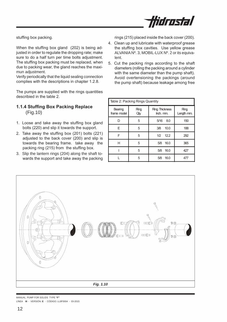
Thepumpsaresuppliedwiththeringsquantitiesdescribiedinthetable2.
1.1.4 Stuffing Box Packing Replace (Fig.10)
1. Looseand takeaway thestuffingboxglandbolts(220)andslipittowardsthesupport.
2. Takeawaythestuffingbox(201)bolts (221)adjusted to thebackcover (200)andslip istowards thebearing frame. takeaway thepackingring(215)fromthestuffingbox.
3. Slip the lantern rings (204) along the shaft to-wardsthesupportandtakeawaythepacking
rings(215)placedinsidethebackcover(200).4. Cleanupandlubricatewithwaterproofgrease
thestuffingboxcavities.UseyellowgreaseALVANIA Nº. 3, MOBIL-LUX Nº. 2 or its equiva-lent.
5. Cut thepacking ringsaccording to theshaftdiameters(rollingthepackingaroundacylinderwiththesamediameterthanthepumpshaft).Avoid overtensioning the packings (aroundthepumpshaft)becauseleakageamongfree
Fig. 1.10
MANUAL PUMP FOR SOLIDS TYPE “F”LÍNEA III - VERSIÓN: E - CÓDIGO: LL8F0004 - 03-2015
13
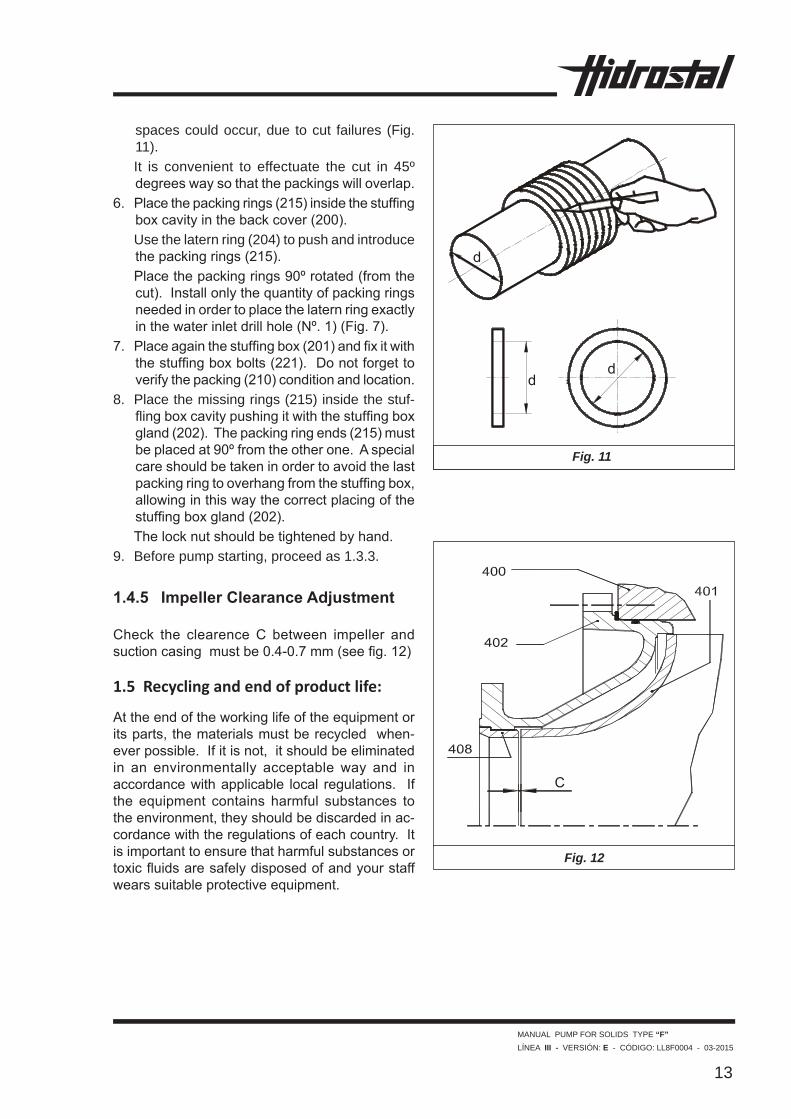
spaces could occur, due to cut failures (Fig. 11).
It is convenient to effectuate the cut in 45º degreeswaysothatthepackingswilloverlap.
6. Placethepackingrings(215)insidethestuffingboxcavityinthebackcover(200).
Use the latern ring (204) to push and introduce thepackingrings(215).
Placethepackingrings90ºrotated(fromthecut).Installonlythequantityofpackingringsneededinordertoplacethelaternringexactlyinthewaterinletdrillhole(Nº.1)(Fig.7).
7. Placeagainthestuffingbox(201)andfixitwiththestuffingboxbolts(221).Donotforgettoverifythepacking(210)conditionandlocation.
8. Place the missing rings (215) inside the stuf-flingboxcavitypushingitwiththestuffingboxgland(202).Thepackingringends(215)mustbeplacedat90ºfromtheotherone.Aspecialcareshouldbetakeninordertoavoidthelastpackingringtooverhangfromthestuffingbox,allowinginthiswaythecorrectplacingofthestuffingboxgland(202).
Thelocknutshouldbetightenedbyhand.9. Before pump starting, proceed as 1.3.3. 1.4.5 Impeller Clearance Adjustment Check the clearenceC between impeller andsuctioncasingmustbe0.4-0.7mm(seefig.12)
1.5 Recycling and end of product life:
Attheendoftheworkinglifeoftheequipmentoritsparts,thematerialsmustberecycledwhen-everpossible.Ifitisnot,itshouldbeeliminatedin an environmentally acceptable way and inaccordancewithapplicable local regulations. Ifthe equipment contains harmful substances totheenvironment,theyshouldbediscardedinac-cordancewiththeregulationsofeachcountry.Itisimportanttoensurethatharmfulsubstancesortoxicfluidsaresafelydisposedofandyourstaffwearssuitableprotectiveequipment.
Fig. 11
Fig. 12

MANUAL PUMP FOR SOLIDS TYPE “F”LÍNEA III - VERSIÓN: E - CÓDIGO: LL8F0004 - 03-2015
14
Table 1: Grease quantity according to bearing frames requirement
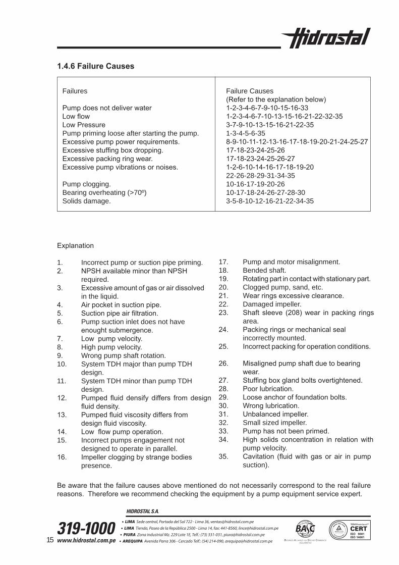
Explanation
1. Incorrect pump or suction pipe priming.2. NPSHavailableminorthanNPSH required.3. Excessiveamountofgasorairdissolved in the liquid.4. Airpocketinsuctionpipe.5. Suctionpipeairfiltration.6. Pump suction inlet does not have enoughtsubmergence.7. Lowpumpvelocity.8. High pump velocity.9. Wrong pump shaft rotation.10. System TDH major than pump TDH design.11. System TDH minor than pump TDH design.12. Pumped fluid densify differs fromdesign fluiddensity.13. Pumpedfluidviscositydiffersfrom designfluidviscosity.14. Lowflowpumpoperation.15. Incorrect pumps engagement not designed to operate in parallel.16. Impellercloggingbystrangebodies presence.
17. Pump and motor misalignment.18. Bended shaft.19. Rotatingpartincontactwithstationarypart.20. Clogged pump, sand, etc.21. Wearringsexcessiveclearance.22. Damaged impeller.23. Shaft sleeve (208)wear in packing rings area.24. Packingringsormechanicalseal incorrectly mounted.25. Incorrectpackingforoperationconditions.
26. Misalignedpumpshaftduetobearing wear.27. Stuffingboxglandboltsovertightened.28. Poorlubrication.29. Looseanchoroffoundationbolts.30. Wronglubrication.31. Unbalancedimpeller.32. Small sized impeller.33. Pumphasnotbeenprimed.34. High solids concentration in relationwith pump velocity.35. Cavitation (fluidwith gasor air in pump suction).
Beawarethatthefailurecausesabovementioneddonotnecessarilycorrespondtotherealfailurereasons.Thereforewerecommendcheckingtheequipmentbyapumpequipmentserviceexpert.
1.4.6 Failure Causes Failures Failure Causes (Refertotheexplanationbelow) Pumpdoesnotdeliverwater 1-2-3-4-6-7-9-10-15-16-33 Lowflow 1-2-3-4-6-7-10-13-15-16-21-22-32-35 LowPressure 3-7-9-10-13-15-16-21-22-35 Pump priming loose after starting the pump. 1-3-4-5-6-35 Excessivepumppowerrequirements. 8-9-10-11-12-13-16-17-18-19-20-21-24-25-27 Excessivestuffingboxdropping. 17-18-23-24-25-26 Excessivepackingringwear. 17-18-23-24-25-26-27 Excessivepumpvibrationsornoises. 1-2-6-10-14-16-17-18-19-20 22-26-28-29-31-34-35 Pump clogging. 10-16-17-19-20-26 Bearing overheating (>70º) 10-17-18-24-26-27-28-30 Solids damage. 3-5-8-10-12-16-21-22-34-35
15