installation, operation and maintenance of airflex...
TRANSCRIPT
©Copyright Eaton Corp., 2006. All rights reserved.
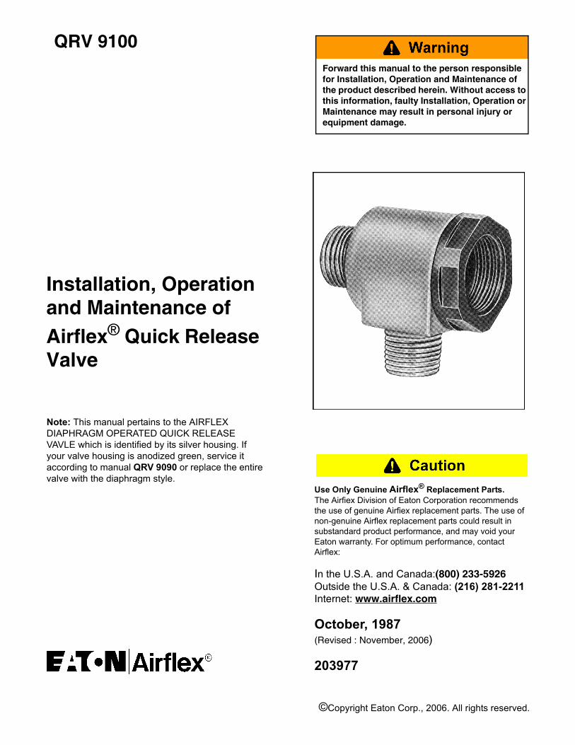
QRV 9100
Installation, Operationand Maintenance ofAirflex® Quick Release Valve
Forward this manual to the person responsible for Installation, Operation and Maintenance of the product described herein. Without access to this information, faulty Installation, Operation or Maintenance may result in personal injury or equipment damage.
Use Only Genuine Airflex® Replacement Parts. The Airfiex Division of Eaton Corporation recommends the use of genuine Airfiex replacement parts. The use of non-genuine Airflex replacement parts could result in substandard product performance, and may void your Eaton warranty. For optimum performance, contactAirflex:
In the U.S.A. and Canada:(800) 233-5926Outside the U.S.A. & Canada: (216) 281-2211Internet: www.airflex.com
October, 1987(Revised : November, 2006)
203977
Note: This manual pertains to the AIRFLEXDIAPHRAGM OPERATED QUICK RELEASE VAVLE which is identified by its silver housing. If your valve housing is anodized green, service it according to manual QRV 9090 or replace the entire valve with the diaphragm style.
QRV 9100 (PDF FORMAT) 1 © Copyright Eaton Corp. 2006, All Rights reserved.
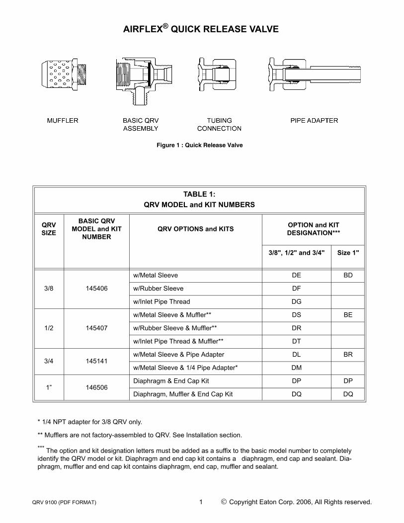
AIRFLEX® QUICK RELEASE VALVE
Figure 1 : Quick Release Valve
TABLE 1:QRV MODEL and KIT NUMBERS
QRVSIZE
BASIC QRV MODEL and KIT
NUMBERQRV OPTIONS and KITS OPTION and KIT
DESIGNATION***
3/8", 1/2" and 3/4" Size 1"
3/8 145406
w/Metal Sleeve DE BD
w/Rubber Sleeve DF
w/Inlet Pipe Thread DG
1/2 145407
w/Metal Sleeve & Muffler** DS BE
w/Rubber Sleeve & Muffler** DR
w/Inlet Pipe Thread & Muffler** DT
3/4 145141w/Metal Sleeve & Pipe Adapter DL BR
w/Metal Sleeve & 1/4 Pipe Adapter* DM
1” 146506Diaphragm & End Cap Kit DP DP
Diaphragm, Muffler & End Cap Kit DQ DQ
* 1/4 NPT adapter for 3/8 QRV only.
** Mufflers are not factory-assembled to QRV. See Installation section.
*** The option and kit designation letters must be added as a suffix to the basic model number to completely identify the QRV model or kit. Diaphragm and end cap kit contains a diaphragm, end cap and sealant. Dia-phragm, muffler and end cap kit contains diaphragm, end cap, muffler and sealant.
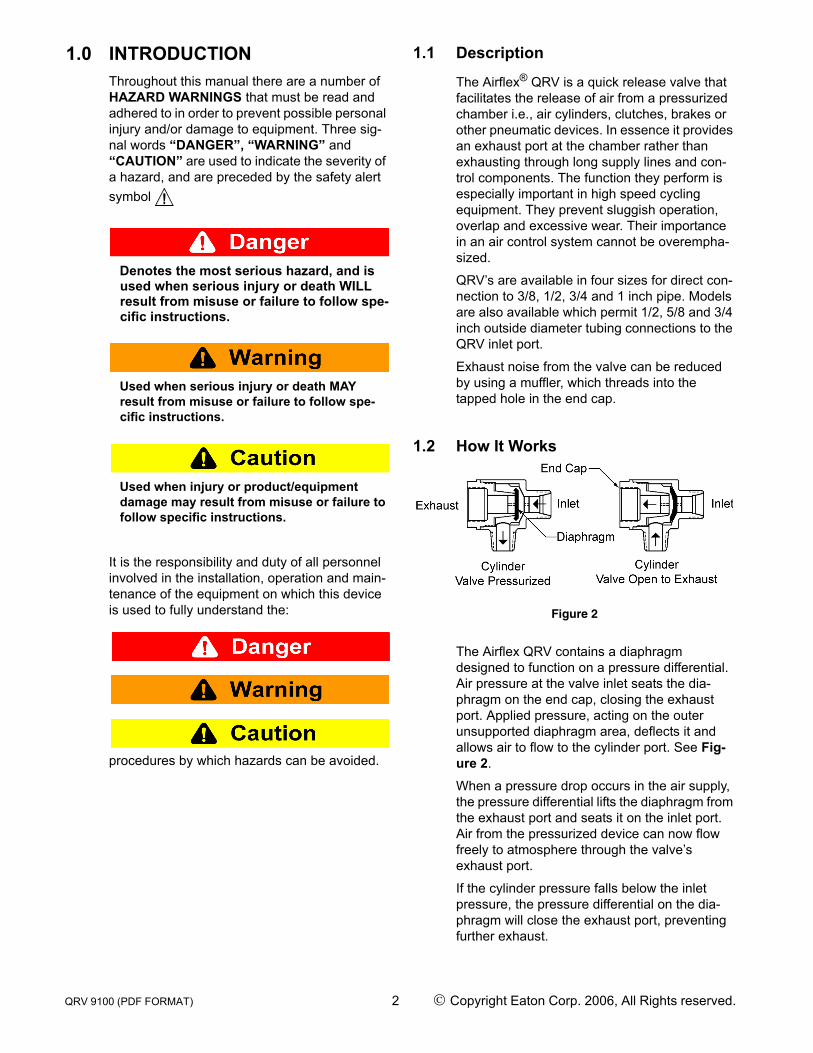
1.0 INTRODUCTIONThroughout this manual there are a number of HAZARD WARNINGS that must be read and adhered to in order to prevent possible personal injury and/or damage to equipment. Three sig-nal words “DANGER”, “WARNING” and “CAUTION” are used to indicate the severity of a hazard, and are preceded by the safety alert symbol
Denotes the most serious hazard, and is used when serious injury or death WILL result from misuse or failure to follow spe-cific instructions.
Used when serious injury or death MAY result from misuse or failure to follow spe-cific instructions.
Used when injury or product/equipment damage may result from misuse or failure to follow specific instructions.
It is the responsibility and duty of all personnel involved in the installation, operation and main-tenance of the equipment on which this device is used to fully understand the:
procedures by which hazards can be avoided.
1.1 Description
The Airflex® QRV is a quick release valve that facilitates the release of air from a pressurized chamber i.e., air cylinders, clutches, brakes or other pneumatic devices. In essence it provides an exhaust port at the chamber rather than exhausting through long supply lines and con-trol components. The function they perform is especially important in high speed cycling equipment. They prevent sluggish operation, overlap and excessive wear. Their importance in an air control system cannot be overempha-sized.
QRV’s are available in four sizes for direct con-nection to 3/8, 1/2, 3/4 and 1 inch pipe. Models are also available which permit 1/2, 5/8 and 3/4 inch outside diameter tubing connections to the QRV inlet port.
Exhaust noise from the valve can be reduced by using a muffler, which threads into the tapped hole in the end cap.
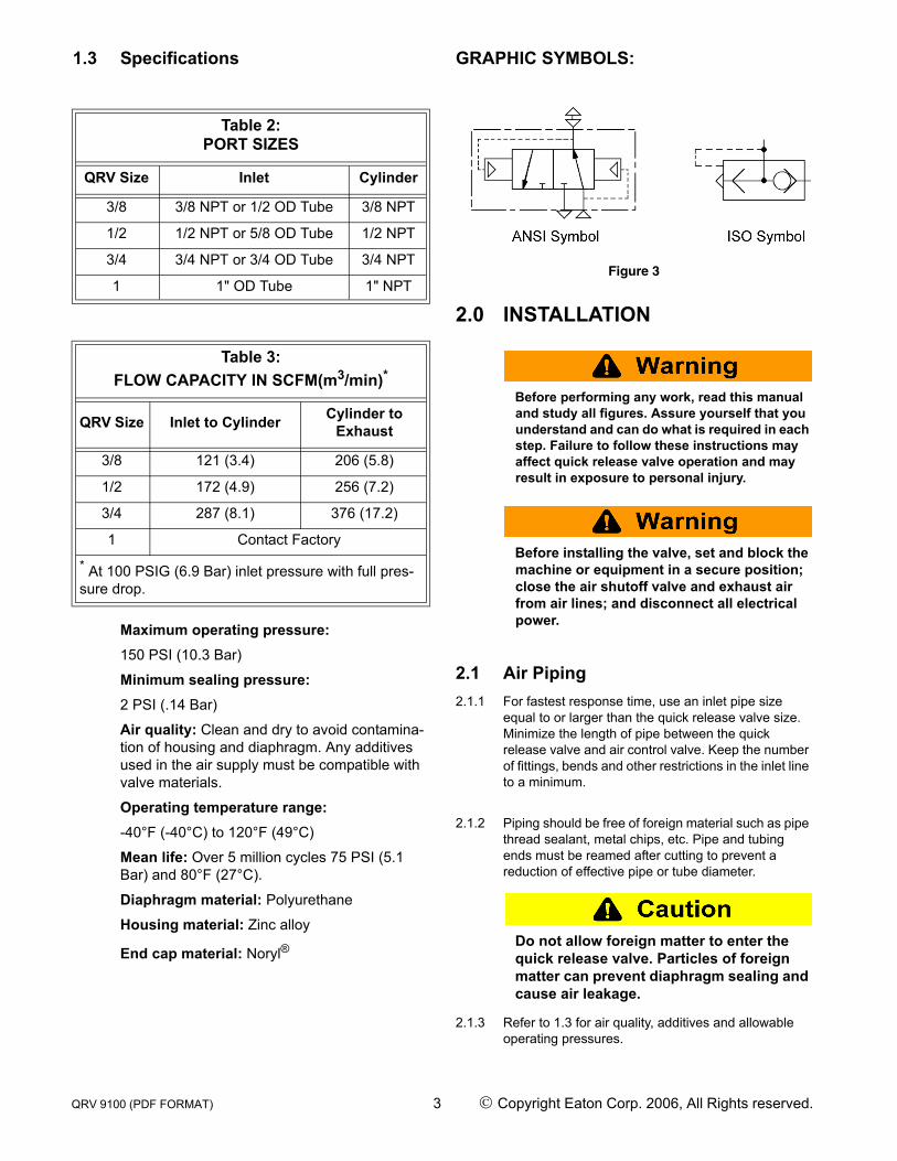
1.2 How It Works
Figure 2
The Airflex QRV contains a diaphragm designed to function on a pressure differential. Air pressure at the valve inlet seats the dia-phragm on the end cap, closing the exhaust port. Applied pressure, acting on the outer unsupported diaphragm area, deflects it and allows air to flow to the cylinder port. See Fig-ure 2.
When a pressure drop occurs in the air supply, the pressure differential lifts the diaphragm from the exhaust port and seats it on the inlet port. Air from the pressurized device can now flow freely to atmosphere through the valve’s exhaust port.
If the cylinder pressure falls below the inlet pressure, the pressure differential on the dia-phragm will close the exhaust port, preventing further exhaust.
QRV 9100 (PDF FORMAT) 2 © Copyright Eaton Corp. 2006, All Rights reserved.
1.3 Specifications
Maximum operating pressure:150 PSI (10.3 Bar)
Minimum sealing pressure:2 PSI (.14 Bar)
Air quality: Clean and dry to avoid contamina-tion of housing and diaphragm. Any additives used in the air supply must be compatible with valve materials.
Operating temperature range:-40°F (-40°C) to 120°F (49°C)
Mean life: Over 5 million cycles 75 PSI (5.1 Bar) and 80°F (27°C).
Diaphragm material: Polyurethane
Housing material: Zinc alloy
End cap material: Noryl®
GRAPHIC SYMBOLS:
Figure 3
2.0 INSTALLATION
Before performing any work, read this manual and study all figures. Assure yourself that you understand and can do what is required in each step. Failure to follow these instructions may affect quick release valve operation and may result in exposure to personal injury.
Before installing the valve, set and block the machine or equipment in a secure position; close the air shutoff valve and exhaust air from air lines; and disconnect all electrical power.
2.1 Air Piping2.1.1 For fastest response time, use an inlet pipe size
equal to or larger than the quick release valve size. Minimize the length of pipe between the quick release valve and air control valve. Keep the number of fittings, bends and other restrictions in the inlet line to a minimum.
2.1.2 Piping should be free of foreign material such as pipe thread sealant, metal chips, etc. Pipe and tubing ends must be reamed after cutting to prevent a reduction of effective pipe or tube diameter.
Do not allow foreign matter to enter the quick release valve. Particles of foreign matter can prevent diaphragm sealing and cause air leakage.
2.1.3 Refer to 1.3 for air quality, additives and allowable operating pressures.
Table 2:PORT SIZES
QRV Size Inlet Cylinder
3/8 3/8 NPT or 1/2 OD Tube 3/8 NPT
1/2 1/2 NPT or 5/8 OD Tube 1/2 NPT
3/4 3/4 NPT or 3/4 OD Tube 3/4 NPT
1 1" OD Tube 1" NPT
Table 3:FLOW CAPACITY IN SCFM(m3/min)*
QRV Size Inlet to Cylinder Cylinder to Exhaust
3/8 121 (3.4) 206 (5.8)
1/2 172 (4.9) 256 (7.2)
3/4 287 (8.1) 376 (17.2)
1 Contact Factory
* At 100 PSIG (6.9 Bar) inlet pressure with full pres-sure drop.
QRV 9100 (PDF FORMAT) 3 © Copyright Eaton Corp. 2006, All Rights reserved.
2.2 Mounting2.2.1 Screw the cylinder port of the quick release valve into
the female port of the device using a minimum of pipe thread sealant. Use a wide, flat faced wrench which will not crimp or damage the valve body. The quick release valve must be torqued enough to pro-duce a tight seal, but not more than the value given in Table 4.
Do not position the quick release valve exhaust port in the up position or allow for-eign matter to enter the valve housing. Parti-cles of foreign matter will enter the exhaust air stream and/or prevent diaphragm seating. Either condition could result in personal injury or damage to equipment.
Position the quick release valve exhaust port so that the exhaust air stream does not strike operating personnel. Particles of for-eign matter picked up by the air stream can cause personal injury.
Position the quick release valve exhaust port so that there are no restrictions to the exhaust air flow. Any restriction will slow down the valve response time.
2.2.2 If the quick release valve has pipe threads on the inlet port, make a direct pipe connection. Do not exceed the tightening torques given in Table 4.
2.2.3 For quick release valves having tubing connections, slide the nut and sleeve onto the inlet air tubing and
insert the tubing or pipe adapter into the valve hous-ing until it bottoms. Slide the sleeve into its seat in the housing. Tighten the nut sufficiently to produce an air seal but not more than the value given in Table 4.
2.2.4 If a muffler is to be used, install per the following instructions.
Loctite® must be used where called for in the following procedure. Mufflers installed without Loctite® may work loose during operation resulting in personal injury.
Note : Quick release valves supplied prior to Sep-tember, 1989 do not have threaded end caps to accept the muffler. The end caps on these valves must be replaced. Refer to the Maintenance sec-tion in this manual for end cap replacement.
Note : Mufflers are not factory-assembled to the quick release valves due to possible interference with the rims of Airfiex clutch elements. When a quick release valve having a muffler is ordered, a basic valve is supplied along with a muffler/end cap/diaphragm kit. If only the muffler is to be installed, discard the end cap and diaphragm included in the kit.
2.2.4.1 Thoroughly clean the female threads in the quick release valve end cap and the male threads on the muffler.
2.2.4.2 Apply Loctite® #222 (included in the kit) to the threads on the muffler, using one drop per thread, and screw the muffler into the end cap. Torque the muffler to 60 lb.-in. (7 Nm).
2.3 Testing2.3.1 Apply air pressure to the quick release valve. The
valve and its connections should not leak under pres-sure. If the valve leaks, refer to the Maintenance sec-tion in this manual.
2.3.2 Cycle the valve several times to ensure proper oper-ation. If the valve response time appears sluggish, check for restrictions in the air supply line.
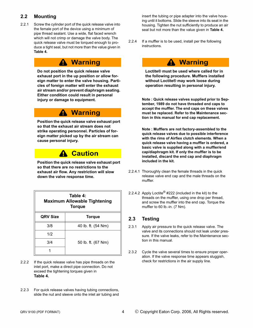
Table 4:Maximum Allowable Tightening
Torque
QRV Size Torque
3/8 40 lb. ft. (54 Nm)
1/2
50 lb. ft. (67 Nm)3/4
1
QRV 9100 (PDF FORMAT) 4 © Copyright Eaton Corp. 2006, All Rights reserved.
3.0 MAINTENANCE
Before performing any work, read this manual and study all figures. Assure yourself that you understand and can do what is required in each step. Failure to follow these instructions may affect quick release valve operation and may result in personal injury.
Two quick release valve replacement kits are available for valve rebuilding. An end cap/dia-phragm kit is available for valves not having mufflers, and contains an end cap, diaphragm and tube of Loctite® #222. An end cap/dia-phragm/muffler kit contains all of the above along with a muffler. It is advisable to stock at least one spare quick release valve for each size used in an installation.
The quick release valve should be periodically checked for proper functioning. If the valve fails to seal, it should be inspected internally. Usually foreign material will be found which has been carried through the piping. If a valve becomes ineffective after prolonged service, it can be restored to good operating condition by rebuild-ing.
3.1 Valve and Diaphragm Service
Before performing any work on the valve, set and block the machine or equipment in a secure position; close the air shutoff valve and exhaust all air from the air lines; and dis-connect all electrical power in order to pre-vent personal injury and/or equipment damage.
3.1.1 If the quick release valve exhaust port is positioned downward, it will be difficult to service the diaphragm. It is recommended that the valve be removed from the equipment and bench-serviced.
3.1.2 Use a flat faced wrench to unscrew the muffler (if present) and the end cap. The diaphragm may fall out of the housing at this time. Discard the end cap, muffler and diaphragm.
Note : The end caps on quick release valves man-ufactured prior to September, 1989, have hex-shaped exhaust ports to accommodate an allen wrench for end cap removal. Refer to Table 5 for the appropriate wrench size to remove the end cap. Discard after removal.
3.1.3 If the diaphragm did not fall out of the housing, gently pry along its outside diameter, being careful not to damage the sealing surface on the housing.
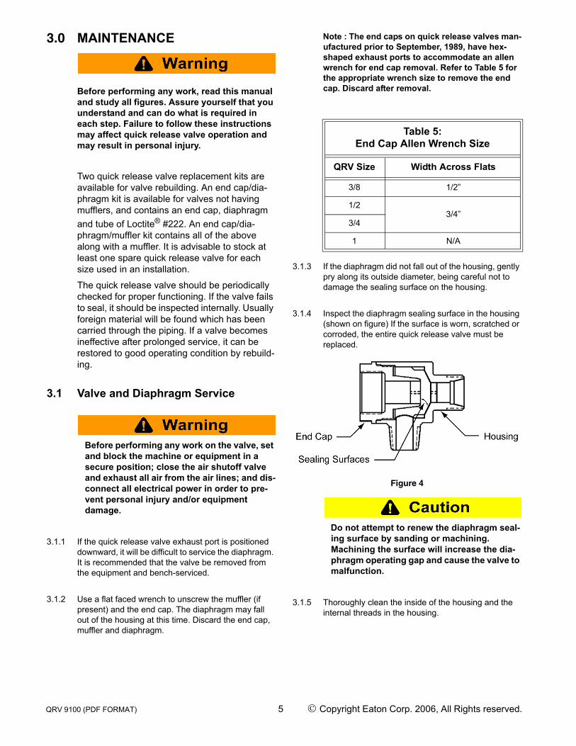
3.1.4 Inspect the diaphragm sealing surface in the housing (shown on figure) If the surface is worn, scratched or corroded, the entire quick release valve must be replaced.
Figure 4
Do not attempt to renew the diaphragm seal-ing surface by sanding or machining. Machining the surface will increase the dia-phragm operating gap and cause the valve to malfunction.
3.1.5 Thoroughly clean the inside of the housing and the internal threads in the housing.
Table 5:End Cap Allen Wrench Size
QRV Size Width Across Flats
3/8 1/2”
1/23/4”
3/4
1 N/A
QRV 9100 (PDF FORMAT) 5 © Copyright Eaton Corp. 2006, All Rights reserved.
Do not allow foreign matter to enter either the valve housing or muffler. Particles of for-eign matter can prevent diaphragm sealing.
3.1.6 Insert a new diaphragm into the housing so it bot-toms against the inlet port.
Loctite® must be used where called for in the following procedure. An end cap and/or muf-fler installed without Loctite® may work loose during operation resulting in personal injury or equipment damage.
3.1.7 Remove and discard the protective cap from the replacement end cap. Apply Loctite® #222 to the threads of the end cap, using one drop per thread, and screw the end cap into the housing. Make sure the diaphragm is located properly in the housing. Torque the end cap to 60 lb-in. (7Nm).
3.1.8 If there is sufficient swing clearance on the equip-ment, the muffler (if applicable) may be installed at this time; otherwise, install the quick release valve and muffler onto the equipment per the Installation section of this manual. When installing the muffler, do not forget to use Loctite® #222 on the muffler threads and torque to 60 lb.-in. (7Nm).
3.2 Testing3.2.1 Test by applying air pressure to the valve. The valve
should not leak under pressure. Removing the air pressure should cause the diaphragm to shift and allow the air to exhaust through the end cap and muffler. If the valve does not function properly, repeat the servicing procedure.
4.0 Ordering Information/Technical Assistance
4.1 In any correspondence regarding Airflex quick release valves, always refer to the size and port configuration and call or write:
Loctite is a registered trademark of Henkle Technolo-gies.
Noryl is a registered trademark of The General Elec-tric Company.
Eaton CorporationAirflex Division9919 Clinton RoadCleveland, Ohio 44144Tel.: (216) 281-2211Fax: (216) 281-3890Internet : www.airflex.eaton.com
QRV 9100 (PDF FORMAT) 6 © Copyright Eaton Corp. 2006, All Rights reserved.
Form ML-318Revised September 3, 1997
EATON PRODUCT WARRANTYSubject to the conditions stated herein, EatonCorporation warrants to the Purchaser thateach new Airflex Product manufactured byEaton will be free from failures caused bydefects in material and workmanship, and willdeliver its rated capacity, for a period of twelve(12) months from the date of shipment to Pur-chaser, provided such Product is properlyinstalled, properly maintained, operated undernormal conditions and with competent supervi-sion. Warranty claims shall, be made in writingand the part or parts shall, if requested by Air-flex Division, be returned prepaid to the AirflexDivision for inspection.Upon a determinationthat a defect exists, Eaton shall thereupon cor-rect any defect, at its option either by repairingany defective part or parts or by making avail-able at Eaton’s plant a repaired or replacementpart. This warranty does not extend to normalwear parts or components of the Product, suchas friction material and friction surfaces.
LIMITATION OF WARRANTYTHE FOREGOING WARRANTY IS EXCLUSIVEAND IN LIEU OF ALL OTHER WARRANTIESWHETHER WRITTEN, ORAL OR IMPLIED. ANYIMPLIED WARRANTY OF MERCHANTABILITYOR FITNESS FOR A PARTICULAR PURPOSEARE SPECIFICALLY EXCLUDED.
In no event shall Eaton be liable for special,incidental or consequential damages. Eaton’sliability arising out of the supplying of suchProduct, or its use, whether in warranty, con-tract or otherwise, shall in no case exceed thecost of correcting defects in the Products asherein provided. Upon expiration of the twelve(12) month period, all such liability shall termi-nate. THE FOREGOING SHALL CONSTITUTETHE SOLE REMEDY OF PURCHASER AND THESOLE LIABILITY OF EATON.
Eaton CorporationAirfiex Division
9919 Clinton RoadCleveland, Ohio 44144