installation, operation and maintenance owner’s manual · and troubleshooting sections, do not...
TRANSCRIPT

Owner’s Manual
Installation, Operation and Maintenance
520192-R_RevA
Aquasana, Inc.6310 Midway RoadHaltom City, TX 76117CUSTOMER SERVICEMon-Fri 8am-8pm CST866-NO-BOTTLE866-662-6885

If it’s NOT a genuine Sterilight part, it shouldn’t be part of your system.
WATER CONFIDENCEEach component of your Aquasana Powered by Sterilight system has been designed and developed through extensive research and development to be part of an overall system that operates safely and ef-ficiently over its entire lifetime. get genuine Sterilight lamps are:
Safety certified. [Replacement with any other lamp voids NSF 55 and UL/CSA/CE certification and compromises safe lamp performance. Using non-genuine lamps results in electrical code no longer being met and safety is at risk.]
Aquasana Powered by Sterilight systems are third-party validated ensuring effective output and disinfection. Tested and proven system performance ensures disinfection is always achieved.
Aquasana Powered by Sterilight lamps are LongLife coated for stability, longer life and increased efficiency. Even lamps that look the same will not perform the same. Get water confidence with genuine lamps proven to disinfect over their entire lifetime.
Environmentally friendly. [With less than 10mg of mercury; 70 per cent less than most other commercially available lamps. Toxicity Characteristic Leaching Procedure compliant, meeting US state requirements regarding the Mercury Phase-Out program.]
Your lamps can be recycled at the end of lamp life. Refer to www.lamprecycle.org for information on recycling in your area.
Aquasana provides its equipment with complete safety certifications and warranty for its compo-nents. Getting genuine ensures maintenance of your system warranty.
Aquasana cannot warranty any system component if non-genuine lamps are used.
Ensure the performance, safety and warranty of your Aquasana Powered by Sterilight systems...get genuine.
Congratulations, you have just purchased the Aquasana Powered by Sterilight UV Disinfection system. By
purchasing this device, you have taken the first step in ensuring the safety of
your water supply by using a totally non-intrusive, physical disinfection method. Your Aquasana Powered by Sterilight system uses the most advanced UV technology on the market and is de-signed to provide you with years of trouble free operation with minimal
maintenance required.

Table of Contents:
Parts / Schematic Breakdown 1
Safety Instructions 2
Water Chemistry 3
Installing Your UV Disinfection System 3-5
Disinfection Procedure 6-7
Operating and Maintenance Instructions 7-9
Operation 9
Troubleshooting 10-11
Dose Flow Chart 11
Specifications 12
*CSA/UL certification with approved power cord and lamps only.
Potential Hazard
Safety Measures
UV Exposure Never illuminate UV Lamp outside of the UV Chamber.
Never look directly at illuminated UV Lamp, even when using protective gear.
Always use protective gear, including gloves and UV safety glasses.
If accidental exposure occurs, immediately cool affected area and consult physician.
Electrical Shock Disconnect power to system before performing any maintenance or repair.
There may be more than one source of power.
Impalement Never perform any physical inspection, repair or maintenance on UV Chamber unless UV
chamber has been isolated and depressurized.
Never service UV Lamps, Sleeves or associated hardware until depressurization of UV
chamber has been confirmed.
Hot chamber Allow UV Lamps, UV Chamber to cool for a minimum of 10 minutes before handling.
Cut or ingestion Ensure the quartz sleeve or lamp is not broken, cracked or damaged in any way when
handling equipment.
Scald from water When there is no water flow, the water in the chamber will become hot. To prevent scalding,
allow the system to cool before draining the system.
Fire Do not store any combustible or flammable material close to the system.
Hg Exposure The UV lamp contains mercury. If the lamp breaks, then avoid inhalation or ingestion of
the debris and avoid exposure to eyes and skin. Never use a vacuum cleaner to clean up a
broken lamp as this may scatter the spilled mercury. Obey local regulations and guidelines
for the removal and disposal of mercury waste.
Water leak Use proper plumbing materials to avoid potential material degradation from UV exposure.
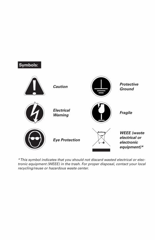
Symbols:
Caution Protective Ground
Electrical Warning Fragile
Eye Protection
WEEE (waste electrical or electronic equipment)*
* This symbol indicates that you should not discard wasted electrical or elec-tronic equipment (WEEE) in the trash. For proper disposal, contact your local recycling/reuse or hazardous waste center.

System Components:
Hard glass, coated Sterilume®-
HO UV lamps for long, consistent life (9000 hours)
S200RL-HO FOR SC200-A
S410RL-HO FOR SC410-A
304 stainless steel reactors
IEC replacement power cords for Cobalt TM (sold separately)
260010 NORTH AMERICAN (NEMA 5-15P), 3-PRONG GROUNDED
602637 CONTINENTAL EUROPEAN (CEE 7/7)2-PIN WITH GROUND, “SCHUKO”
260012 UK VERSION (BS 1363)3-PRONG GROUNDED (5 AMP FUSE)
260013 AUSTRALIAN VERSION (AS 3112)3-PRONG GROUNDED
260019 NO CONNECTOR, 3-WIRE, BARE LEADS
lamp connector
1
gland nut
RN-001
o-ring
410867
214 fused quartz sleeves with fire polished ends
QS-001 FOR SC200-A
QS0-410 FOR SC410-A
Controller
POWER - 100-240V/50-60HZ
BA-ICE-C COBALT SYSTEM
2
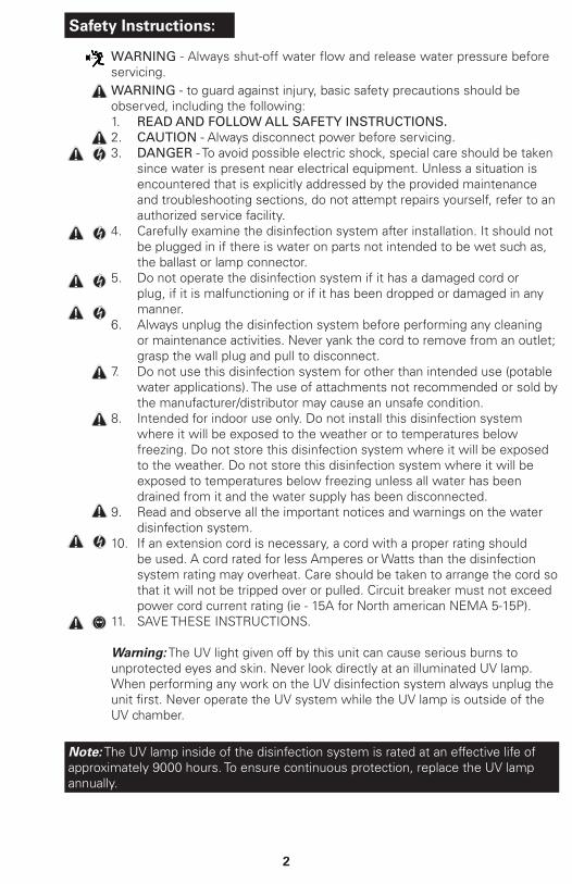
Safety Instructions:
WARNING - to guard against injury, basic safety precautions should be observed, including the following:1. READ AND FOLLOW ALL SAFETY INSTRUCTIONS.2. CAUTION - Always disconnect power before servicing.3. DANGER - To avoid possible electric shock, special care should be taken
since water is present near electrical equipment. Unless a situation is encountered that is explicitly addressed by the provided maintenance and troubleshooting sections, do not attempt repairs yourself, refer to an authorized service facility.
4. Carefully examine the disinfection system after installation. It should not be plugged in if there is water on parts not intended to be wet such as, the ballast or lamp connector.
5. Do not operate the disinfection system if it has a damaged cord or plug, if it is malfunctioning or if it has been dropped or damaged in any manner.
6. Always unplug the disinfection system before performing any cleaning or maintenance activities. Never yank the cord to remove from an outlet; grasp the wall plug and pull to disconnect.
7. Do not use this disinfection system for other than intended use (potable water applications). The use of attachments not recommended or sold by the manufacturer/distributor may cause an unsafe condition.
8. Intended for indoor use only. Do not install this disinfection system where it will be exposed to the weather or to temperatures below freezing. Do not store this disinfection system where it will be exposed to the weather. Do not store this disinfection system where it will be exposed to temperatures below freezing unless all water has been drained from it and the water supply has been disconnected.
9. Read and observe all the important notices and warnings on the water disinfection system.
10. If an extension cord is necessary, a cord with a proper rating should be used. A cord rated for less Amperes or Watts than the disinfection system rating may overheat. Care should be taken to arrange the cord so that it will not be tripped over or pulled. Circuit breaker must not exceed power cord current rating (ie - 15A for North american NEMA 5-15P).
11. SAVE THESE INSTRUCTIONS.
Warning: The UV light given off by this unit can cause serious burns to unprotected eyes and skin. Never look directly at an illuminated UV lamp. When performing any work on the UV disinfection system always unplug the unit first. Never operate the UV system while the UV lamp is outside of the UV chamber.
Note: The UV lamp inside of the disinfection system is rated at an effective life of approximately 9000 hours. To ensure continuous protection, replace the UV lamp annually.
WARNING - Always shut-off water flow and release water pressure before servicing.
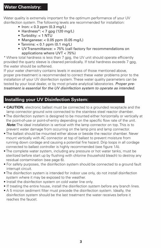
Water Chemistry:
Water quality is extremely important for the optimum performance of your UV disinfection system. The following levels are recommended for installation:
• Iron: < 0.3 ppm (0.3 mg/L)• Hardness*: < 7 gpg (120 mg/L)• Turbidity: < 1 NTU• Manganese: < 0.05 ppm (0.05 mg/L)• Tannins: < 0.1 ppm (0.1 mg/L)• UV Transmittance: > 75% (call factory for recommendations on
applications where UVT < 75%)* Where total hardness is less than 7 gpg, the UV unit should operate efficiently provided the quartz sleeve is cleaned periodically. If total hardness exceeds 7 gpg, the water should be softened.If your water chemistry contains levels in excess of those mentioned above, proper pre-treatment is recommended to correct these water problems prior to the installation of your UV disinfection system. These water quality parameters can be tested by your local dealer, or by most private analytical laboratories. Proper pre-treatment is essential for the UV disinfection system to operate as intended.
Installing your UV Disinfection System:
• CAUTION, electronic ballast must be connected to a grounded receptacle and the lamp connector ground wire connected to the stainless steel reactor chamber.
• The disinfection system is designed to be mounted either horizontally or vertically at the point-of-use or point-of-entry depending on the specific flow rate of the unit.
Note: The ideal installation is vertical with the lamp connector on top. This is to prevent water damage from occurring on the lamp pins and lamp connector.
• The ballast should be mounted either above or beside the reactor chamber. Never mount vertically with AC connector at top of ballast to prevent moisture from running down cordage and causing a potential fire hazard. Drip loops in all cordage connected to ballast controller is highly recommended (see figure 1A).
• The complete water system, including any pressure or hot water tanks, must be sterilized before start up by flushing with chlorine (household bleach) to destroy any residual contamination (see page 6).
• For safety purposes, the disinfection system should be connected to a ground fault interrupt circuit.
• The disinfection system is intended for indoor use only, do not install disinfection system where it may be exposed to the weather.
• Install the disinfection system on cold water line only.• If treating the entire house, install the disinfection system before any branch lines.• A 5 micron sediment filter must precede the disinfection system. Ideally, the
disinfection system should be the last treatment the water receives before it reaches the faucet.
3

4
1. It must be noted that the system will require supplementary disinfection of the distribution system if any water is used during a by-pass condition. In addition, during by-pass, the water will NOT be disinfected and the attached “DO NOT CONSUME THE WATER” tag (included with the system), should be physically installed on the by-pass assembly until such time as the system is sanitized and returned to service. Please refer to the complete disinfection procedure as outlined on page 6 of this document. If the water is to be consumed while the system is off-line, the water must be boiled for twenty minutes prior to consumption.
2. Select a suitable location for the disinfection system and its related components. As it is recommended to install a ground fault protected circuit (GFCI), make sure that this is taken into consideration prior to any installation. The system can either be installed vertically (inlet port at the bottom) (Figure 1A), or horizontally, however the vertical installation is the most preferred method. When selecting a mounting location, you must also leave enough space to allow for the removal of the UV lamp and/or quartz sleeve (typically leave a space equal to the size of the reactor chamber itself).
3. Mount the system to the wall using the supplied clamps. Various connection methods can be used to connect the water source to the system. DO NOT SOLDER CONNECTIONS WHILE ATTACHED TO THE SYSTEM AS THIS COULD DAMAGE THE O-RING SEALS.DAMAGE THE O-RING SEALS.
1812

5
4. Mount the remove ICE controller horizontally to the wall, near the reactor chamber. Ideally place the controller above the reactor and away from any water connection point, to prevent any water from potentially leaking onto the controller by means of a leak at a connection point or a “sweating” system. Make sure you allow for a “drip-loop” on the lamp, sensor and power cord, again, to prevent any water from potentially entering the controller.
5. Install the UV lamp as outlined on pages 7-8.
6. When all plumbing connections are made, slowly turn on the water supply and check for leaks. The most likely cause for leaks is from the o-ring seal. In case of a leak, shut water off, drain cell, remove the retaining nut, wipe the o-ring and threads clean and re-install.
7. Once it is determined that there are no leaks, plug the system into the ground fault interrupter, and check controller to ensure the system is operating properly. The controller is designed to detect both power to the system and lamp illumination. It is important to NEVER LOOK DIRECTLY AT THE GLOWING UV LAMP.
8. Allow the water to run for a few minutes to clear any air or dust that may be in the reactor. PLEASE NOTE: When there is no flow, the water in the cell will become warm, as the UV lamp is always on. To remedy this, run a cold water tap anywhere in the house for a minute to flush out the warm water.

Disinfection Procedure:
UV disinfection is a physical process and does not add any potentially harmful chemicals to the water. As UV does not provide a disinfection residual, it is imperative that the entire distribution system located after the UV be chemically disinfected to ensure that the water is free from any bacteriological contaminants. The disinfection process must be performed immediately after the UV unit is installed and repeated thereafter whenever the UV is shut down for service, without power, or inoperative for any reason. The procedure for sanitizing the plumbing system is readily accomplished as follows:
1. Shut off the upstream water supply that feeds water into the reactor chamber and depressurize water system. Remove the cartridge from the filter housing located before the UV system. and fill the sump with 1-2 cups of household (5.25%) bleach (chlorine) – Do NOT use hydrogen peroxide. At all times during this process, make sure the UV unit (and lamp) is turned on and operational!
2. Repressurize water system, open each faucet and allow cold water to run until you smell chlorine, shut the faucet off and then repeat the process for each faucet, including hot water. You must ensure that all taps, including outside faucets, dishwashers, shower heads, washing machines, connections to refrigerators, toilets, etc., pass chlorinated water.
3. Once all the locations have passed the chlorine disinfection solution, you will need to leave the solution sit for a period of 20–30 minutes. Reinstall the pre-filter cartridge into the filter and then flush the chlorine solution from the system until no chlorine smell is detectable. Make sure that each fixture that was disinfected in step two is completely flushed of the chlorine solution as the consumption of this water is not advised due to the extremely high concentrations of chlorine. It is important to remember that in the event that a UV is briefly shut down for routine cleaning or during power interruptions where water could have passed through the system, the aforementioned procedure must also be followed.
Note A: The addition of chlorine (bleach) to a hot water tank that has in the past been fed with untreated raw water with high levels of other contaminants (iron, manganese, hydrogen sulphide, organics, etc.) will result in oxidation of these contaminants and may require repeated flushing of the hot water tank. This contingency must be dealt with independently under the start-up procedure for any other conditioners that may form a part of the pre-treatment for the UV unit. Note B: The above procedure (Steps 1 to 3) will result in a massive chlorine residual far in excess of the 0.5 to 1.0 mg/L typically present in municipally chlorinated water and of a magnitude consistent with the minimum 50 mg/L chlorine solution recommended for the disinfection of distribution systems known to be contaminated. Do not consume water until complete system has been flushed.
6

OPERATION• Always disconnect power before performing any work on the disinfection system.• Regularly inspect your disinfection system to ensure that the power indicators are
on and no alarms are present.• Replace the UV lamp annually (or biennially if seasonal home use) to ensure
maximum disinfection.• Always drain the reactor chamber when closing a seasonal home or leaving the
unit in an area subject to freezing temperatures.
Operating & Maintenance Instructions:
UV Lamp Replacement:NOTE: RESET LAMP LIFE TIMER AFTER LAMP REPLACEMENT (PG 10) – refer to www.lamprecycle.org for lamp disposal1. DO NOT USE WATER DURING THIS PROCEDURE. Lamp
replacement is a quick and simple procedure requiring no special tools.The UV lamp must be replaced after 9,000 hours of continuous operation (approximately one year) in order to ensure adequate disinfection.
2. Disconnect main power source and allow the unit to power down for 30 sec. Remove the lamp connector by squeezing the plastic locking tabs on the side of the connector. Remove connector and lamp from the reactor chamber. and lamp connector base. Separate the lamp from the connector (Figure 2B). Do not twist the lamp from the connector, simply slide the two apart. Avoid touching the lamp on the glass portion. Handling the lamp at the ceramic ends is acceptable, however if you must touch the lamp glass, please use gloves or a soft cloth. Fully remove the lamp from the reactor chamber being careful not to angle the lamp as it is removed from the chamber. If the lamp is removed on an angle, pressure will be applied on the inside of the quartz sleeve, causing the sleeve to fracture.
3. To install a new lamp, first remove the lamp from its protective packaging, again being careful not to touch the lamp glass itself. Carefully insert the lamp into the reactor vessel (actually inside the quartz sleeve) (Figure 2C). Insert the lamp fully into the chamber leaving about two inches of the lamp protruding from the chamber. Next, attach the connector to the UV lamp (Figure 2B). The connector is “keyed” and will only allow correct installation in one position. Ensure the connector is fully seated onto the UV lamp (Figure 2D).
4. Once the lamp is fully seated on the connector, slide the connector over the retaining nut and lamp connector base. Push the lamp connector and lamp connector base together until an audible click is heard.
FIGURE 2A
FIGURE 2B
FIGURE 2C
7
Caution: prior to performing any work on the disinfection system, always disconnect the power supply first. Do not use water during following procedures.Warning: Always shut-off water flow and release water pressure before servicing.

8
Quartz Sleeve Replacement / Cleaning:Mineral deposits and sediment may accumulate on the quartz sleeve decreasing the UV energy required for adequate disinfection. Good maintenance of filtration equipment will reduce the accumulation of residues. If necessary, remove the quartz sleeve and clean with a commercially available scale remover (CLR, Lime-Away, etc.) and a lint free cloth. Repeat the process as often as necessary to keep the quartz sleeve clean. Be sure to remove all traces of cleaning fluid from the sleeve before it is reinstalled in the reactor (be sure not to allow liquid inside the sleeve).1. To remove the quartz sleeve, first remove the UV lamp as outlined
in step 1-2 (page 7) then perform the following steps:a) Shut off water supply and drain all lines.b) Remove the lowest connection on the disinfection system and
drain the UV chamber (use a small bucket under the unit to prevent a spill).
c) Remove gland nuts from both ends of the reactor chamber (Figure 3A), checking for the free floating spring inside sleeve at the opposite end to the lamp connection (do not allow quartz sleeve to fall).
d) Carefully remove o-rings from the quartz sleeve (Figure 3A). As the o-ring may tend to adhere to the quartz sleeve, it is recommended to replace the o-rings annually. Remove quartz sleeve carefully from chamber.
e) Clean the outside of the quartz sleeve with a cloth soaked in CLR, vinegar or some other mild acid and then rinse.
f) Re-assemble the quartz sleeve in the UV chamber allowing the sleeve to protrude an equal distance from both ends of the UV chamber (Figure 3B).
g) Wet the o-rings and slide onto each end of the quartz sleeve and reassemble the gland nuts (hand tight is sufficient), slide spring into quartz sleeve. Use new o-rings supplied.
h) Re-tighten all connections, turn on water slowly and check for leaks.
i) Re-install the UV lamp and lamp connector as per UV Lamp Replacement instructions on page 7.
j) Plug in ballast and verify the POWER-ON LED display is illuminated and ballast power-up sequence operates.
Note: If the system is put on a temporary by-pass or if it becomes contaminated after the disinfection system, it will be necessary to shock the system with household bleach for a full 20 minutes before resuming the use of the water.
FIGURE 2D
FIGURE 2E
FIGURE 3A
FIGURE 3B

Operation:
Controller:
9
1. Lamp life remaining (days):The controller tracks the number of days of operation of the lamp and the controller. The default screen will display the total lamp life remaining (in days). The controller will count down the number of days remaining until the lamp requires changing (365 days to 1 day). At “0” days, the controller will display on the display and supply an intermittent audible chirp (1 second on, 5 seconds off), indicating the need to change the lamp.DEFERRAL - Once the “A3” or end of lamp life message is shown on the LED screen, the audible alarm can be deferred up to 4 separate times. The delay switch is designed to allow you time to address the alarm while you obtain a new UV lamp. This can be done by simply depressing the push-button “RESET” switch, which is located on the left side of the controller. Each time the reset switch is pressed the controller alarm is deferred seven days. Once the final 7 day deferral has been reached the alarm can only be silenced by changing the UV lamp and manually resetting the controller timer. To do this please follow the step by step instructions below: RESETTING LAMP LIFE: 1. disconnect power supply from controller 2. remove expired lamp from the reactor chamber (refer to www.lamprecycle.org for lamp disposal) 3. install new UV lamp and connect it to lamp connector (refer to page 7) 4. replace lamp connector 5. hold down the “RESET” switch while reapplying power to the controller until you see “rSEt”, then release 6. 5 second delay will occur until you hear an audible tone & LED display will read once again Once you hear the tone, let go of the switch and the counter will be reset. Even though the alarm on the system can be deferred for a period of time, it is important to address each and every alarm condition as they are indicating that there is a potential problem with the system and should be remedied. 2. Total days of operation:The controller also displays the total running time of the controller. To obtain this reading, press the push-button SWITCH once. The total running time of the controller will be numerically displayed in days. This information will remain displayed for ten seconds and will then revert back to the lamp life remaining default screen. It should be noted that this value cannot be reset.
3. Lamp failure (blank screen):When the system recognizes LAMP FAILURE (no current running through the lamp), the 4-segment display will be blank (no default LAMP LIFE REMAINING screen) and the system will supply an intermittent audible tone (1 second on, 1 second off). The system will remain in this state, until this condition is remedied.

Troubleshooting:
TROUBLESHOOTING GUIDE
Symptom Possible Causes Solutions
Pressure Drop Sediment filter clogged
• replace filter cartridge with appropriate 5 micron cartridge
Note: check source water supply as fluctuations may occur in source pressure
High Bacteria Counts
Quartz sleeve is stained or dirty
• clean sleeve with scale cleaner and eliminate source of staining problem (ie. soften hard water, see page 8)
Change in feed water quality
• have source water tested to ensure that water quality is still within allowable limits for this system
Contamination in water lines after UV system
• it is imperative that effluent water stream be shocked with chlorine (bleach) before water leaves UV system - disinfection system must have a bacterial free distribution system to work effectively (see page 6)
Possible break-through of sediment through pre-filter
• have source water tested for turbidity - may need stepped filtration in order to catch all sediment entering water system (20 micron filter followed by a 5 micron filter followed by UV system)
Heated Product Water
Common problem caused by infrequent use of water
• run water until it return to ambient temperature
• install temperature management valve
Water Appears Milky
Caused by air in the water lines • run water until air is purged
ChamberLeaking Water
Problem with o-ring seal (on gland nut and/or UV sensor)
• ensure o-ring is in place, check for cuts or abrasions, clean o-ring, moisten with water/ lubricant and re-install, replace if necessary (410867)
Condensation on reactor chamber caused by excessive humidity & cold water
• check location of disinfection system and control humidity
Inadequate inlet/outlet port connections
• check thread connections, reseal with Teflon® tape and re-tighten
System Shutting Down Intermittently
Interrupted power supply
• ensure system has been installed on its own circuit, as other equipment may be drawing power away from UV (ie. pump or fridge)
• UV system should not be installed on a circuit which is incorporated into a light switch
Lamp Failure Alarm on - New Lamp
Loose connection between lamp and connector
• disconnect lamp from connector and reconnect, ensuring that a tight fit is accomplished
Moisture build up in connector may keep lamp and connector from making a solid connection
• eliminate chance of any moisture getting to the connector and/or lamp pins
10

11
DISPLAY FAULT MODES
LED display reads “A3”
• lamp life expired - countdown is at “0” days• press reset button for a deferred alarm, replace UV lamp
LED display is blank
• controller is in lamp failure mode• power system down, allowing it to reset itself; apply power in order to
confirm that the controller is able to power lamp• check to see if there is sufficient power to the UV system
Dose Flow Chart:
0
5
10
15
20
25
30
35
40
0 5 10 15 20 25 30 35 40 45
FLOW RAT
E (U.S. gpm
)
UV DOSE (FLUENCE) (mJ/cm2)
SC200-‐A
SC410-‐A
Note: dosages based on 95% UVT at end of lamp life (0.80 EOLL)
`
1966 US Public Health
Manufacturers Standard
NSF/EPA Standard
AquaSana Series Dose Chart:
E. Coli eradicated at 6.6mJ/cm2
Cryptosporidium &Giardia eradicated at <10mJ/cm2

12
Specifications:
MODEL SC200-A SC410-A
Flo
w R
ate1
US Public Health16mJ/cm2
56.8 lpm (15 gpm)
(3.4 m3/hr)
111.2 lpm(29.4 gpm)(6.7 m3/hr)
VIQUA Standard30 mJ/cm2
30.3 lpm (8 gpm)
(1.8 m3/hr)
59.3 lpm(15.7 gpm)(3.6 m3/hr)
NSF/EPA40mJ/cm2
22.7 lpm (6 gpm)
(1.4 m3/hr)
44.5 lpm(11.7 gpm)(2.7 m3/hr)
Overall Dimensions(width x Depth x Height)
34.3 x 8.9 cm(13.5” x 3.5”)
55.4 x 8.9 cm(21.8” x 3.5”)
Inlet/Outlet Port Size1“ FNPT/
Combo 3/4“ FNPT & 1“ MNPT
1“ FNPT/Combo 3/4“ FNPT &
1“ MNPT
Shipping Weight 5.1kg (11.3lbs) 6.8kg (15.0lbs)
Ele
ctri
cal Voltage 100-240V/50-60Hz 100-240V/50-60Hz
Power Consumption
35 W 60 W
Lamp Watts 27 W 46 W
Maximum Operating Pressure 8.62bar (125psi) 8.62bar (125psi)
Ambient Water Temperature
2-40˚C (36-104˚F) 2-40°C (36-104°F)
Lamp TypeSterilume™-HO
(high-output)Sterilume™-HO
(high-output)
Visual “Power-On” Yes Yes
Audible Lamp Failure Yes Yes
Lamp Replacement Reminder Yes Yes
Visual Lamp Life Remaining
Yes Yes
Total Running Time Yes Yes
254nm UV Monitor No No
Solenoid Output (solenoid not incl.)
No No
Chamber Material 304 SS 304 SS1. Flow rates stated @ 95% UVT EOL
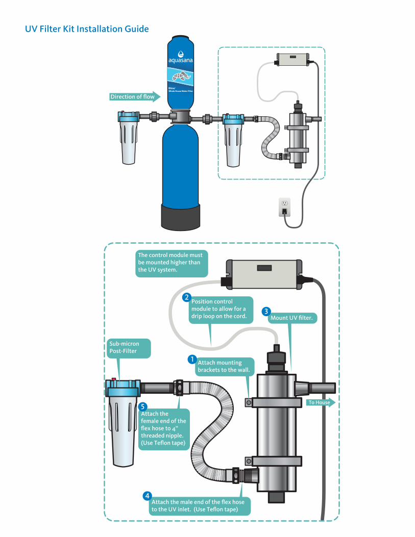
UV Filter Kit Installation Guide
The control module must be mounted higher than the UV system.
Sub-micronPost-Filter
Attach mounting brackets to the wall.
Mount UV filter.
Direction of flow
To House
Attach the male end of the flex hose to the UV inlet. (Use Teflon tape)
Attach the female end of the flex hose to 4” threaded nipple. (Use Teflon tape)
Position control module to allow for a drip loop on the cord.
1
2
3
4
5
Rhino®
Whole House Water Filter