installation, operation and warranty information
TRANSCRIPT

�
DOC No: 7936 REV C
INSTALLATION, OPERATION AND WARRANTY INFORMATIONI-DrIve®

�
DOC No: 7936 REV C
Signature of Manufacturer
EC DECLARATION OF INCORPORATION
Herewith we declare that the motors described in this Installation, Operation, and War-ranty Handbook comply with the following provisions applying to it:
Machinery Directive 98/37/EC (Annex IIB) as amendedEMC Directive 89/336/EC as amended Low Voltage Directive 73/23/EC as amended
Applied harmonized standards, in particular: ISO12100-1:2003 (Replacing EN292-1:1991) ISO12100-2:2003 (Replacing EN292-1:1991)EN14121:2001 (Replacing EN1050:1999) EN60204-1:2006EN60950-1:2002 EN563:1994 EN60529:1992 EN55014-1:2001EN55014-2L1997 EN61000-3-2:2001EN61000-3-3:1995 EN61000-4-2:1995EN61000-4-3:2002 EN61000-4-4:2004EN61000-4-5:1995 EN61000-4-6:1996EN61000-4-8:1994 CISPR16-2-1:2003
Manufacturer: Importer in country of use:
Micropump LimitedA Subsidiary of Micropump Inc.Howard Road, Eaton SoconSt. Neots, Cambridgeshire PE 19 8ET England
Signature of Importer
The machinery described in this certificate must not be put into service until the machinery in which it is incorporated has been declared in conformity with the provisions of the Machinery Directive and their amendments.
PUBLISHED BY
MICROPUMP INC.A Unit of IDEX CorporationMarch 2006 © Micropump Inc.All rights reserved.This manual contains proprietary information which is protected by copyright.No part of this publication may be reproduced, transcribed, stored in a retrieval system, translated into any language (including computer language), or transmitted in any form without the written consent of the publisher. For further information contact your local Micropump distributor. Every effort has been made to ensure that the information contained in this manual is accurate prior to printing. However, the products described in this manual are subject to continuous development and improvement and Micropump shall not be liable for any errors contained herein or for incidental or consequential damages in connection with the furnishing, performance, or use of this manual.

�
DOC No: 7936 REV C
STANDARD LIMITED WARRANTY
The products manufactured by Micropump Incorporated are warranted to be free from defects in workmanship and material at the time of shipment from the place of manufacture. Micropump will repair or replace, at its option, any part or component which fails to conform to this warranty for a period of one year. Micropump’s obligation under this warranty is limited to the repairs or replacement of defective equipment returned to Micropump on an F.O.B. destination and freight-prepaid basis. All normal wear and tear is excepted, and product is subject to examination at Micropump to verify that the parts or components were defective at the time of sale.
For the purposes of the limited warranties, the “Stator/Controller Assembly” means only the stator and the printed circuit board and electronic components contained in the controller housing, plus the connecting control and power cables. The “Power Supply Assembly” means only the printed circuit board and the electronic or mechanical components located inside or on the power supply enclosure and the “Pump head Assembly” means all other parts of the product, including but not limited to, the rotor.
No warranty of any kind is made or shall be imposed with respect to any pump or parts (1) that have not been properly installed and tested in operation, (2) that have been subject to misuse, negligence, acts of God or the elements, or any other form of casualty, or (3) that have been repaired or altered outside Micropump’s facility in a way, so as, in our judgment, to affect performance or reliability.
The parties agree that the buyer’s sole and exclusive remedy against Micropump shall be for repair or replacement of defective parts under the conditions stated above. The buyer agrees that no other remedy (including but not limited to incidental or consequential damages for lost profits, lost sales, loss of use, injury to person or property, or any other incidental or consequential loss) shall be available to them.
This warranty shall not apply to prototype pumps, experimental pumps, or brush-type electric motors. Warranty of equipment or accessories from outside sources, purchased by Micropump and incorporated into Micropump’s product is subject to the manufacturer’s standard warranty, unless specifically agreed otherwise between Micropump and buyer. A copy of the warranty on the aforementioned equipment is available on request.
The adjustment or replacement of defective parts made under this warranty will not extend the original warranty period.
THE WARRANTY DESCRIBED ABOVE IS THE EXCLUSIVE MICROPUMP WARRANTY AND IS IN LIEU OF ALL OTHER WARRANTIES, EXPRESSED OR IMPLIED, INCLUDING ANY WARRANTY OF MERCHANTABILITY OR FITNESS FOR A PARTICULAR PURPOSE OR ANY WARRANTY PREVIOUSLY ISSUED. WE NEITHER ASSUME NOR AUTHORIZE ANY PERSON TO ASSUME FOR US ANY OTHER LIABILITY IN CONNECTION WITH THE SALE OR USE OF OUR EQUIPMENT.

�
DOC No: 7936 REV C
represents years of fluid handling experience and we feel it is the finest product available of its type.
The product you have purchased was designed and constructed for use within designated limits and conditions. Staying within performance limits and following the guidelines given in this manual will result in excellent performance and maximum life.
Should you have a question or a problem, technical assistance is available worldwide.Micropump products are designed for easy field servicing with service kits and technical support available for all products.
The Purpose of this Guide...is to provide information to enable suitably qualified technicians and fitters to install, operate and maintain the Micropump I-Drive and common pump/motor combinations.
Use the Guide...when you have purchased a motor or pump/motor combination. This guide contains specific information for installation, operation, and maintenance of the I-Drive and references some of the most common pump/motor combinations. This guide should be read in conjunction with the instructions provided with your specific pump. General information is given on installation within a system, but reference should always be made to instructions provided with ancillary equipment when installing the unit.
AbbreviationsThe following abbreviations are used in this guide:
°C Degrees Celsius °F Degrees Fahrenheit EMC Electromagnetic Compliance DC Direct CurrentLVD Low Voltage Directive IOM Installation, Operation and Maintenance ManualMax Maximum Min MinimumRPM Revolutions Per Minute SELV Safety Electric Low VoltageV Volt(s) W Watt(s)
Bracket /Flange
Power Option
Driving Magnet
Motor Options Code:
Product LabelingMicropump products are labeled with a product code. The code describes the I-Drive configuration. The first nine positions of the code describe the base configuration. The remaining three positions in the code describe the optional features. Options that are not used are not shown in the code. For pump/motor assemblies the product code consists of the first four positions of the pump code with later positions describing the adaptor and/or motor. Your Micropump distributor can provide additional information about the product code.
Type Series Modifier Rated Torque
Speed Range
Input Power
PortFittings
Enclosure Mount
Motor Code:
Your Micropump Product...

�
DOC No: 7936 REV C
The following are used throughout this guide to indicate procedure that, if not followed correctly, may result in injury to personnel or damage to equipment.
Warnings are used to alert the reader to a procedure or practice, which if not followed correctly, could result in personal injury.
Limits of Use 6
Installation in Explosive and Fire Danger Zones 7
Description 7
Function 7
Unpacking and Storage 8
Assembly 8
Space Requirements 8
Location 9
Bulkhead Mounting 9
EMC Compatibility 9
Electrical Connection 10
Lead Assignments 12
Operation 13
Manual Control Adjustment 14
Magnet Decoupling 15
Maintenance 15
Fault Isolation 16
Technical Specification 17-19
Notes 20-22
Table of Contents
CAUTION
NOTE
Warning - Hot Surface is used to alert the reader to a procedure or practice, which if not followed correctly, could result in personal injury due to contact with a hot surface.
Cautions are used to alert the reader to a procedure or practice, which if not followed correctly, could result in damage to the pump, motor, or ancillary equipment.
Notes are used to highlight important information that may assist the reader in carrying out a procedure or in understanding the text.
Safety

�
DOC No: 7936 REV C
Limits of UseThe I-Drive motor is intended for use with pumps handling fluids in a variety of pumping systems. These fluids may be innocuous or hazardous, depending on the specific application. You should contact your local Micropump distributor or contact Micropump directly about special limitations of your pump/motor unit with regard to your specific system.
To achieve optimum performance and safe operation Micropump products must be operated with the limits given in the Technical Specification. Operation outside these limits is not recommended and may result in damage to the pump, motor, and/or ancillary equipment.
Temperature. Operating beyond the maximum operating temperature given in the Technical Specification is not recommended and may result in damage to the product and compromise safety by creating high surface temperature.
CAUTION
CAUTION
CAUTION
Corrosive Liquids. Corrosive liquids may eventually produce leak paths around the sealing surfaces of the product. The product should be inspected for leaks on a regular basis.
Flooding and Water Immersion. The products covered by this guide are not designed to operate immersed in water. Refer to the Technical Specification for the environmental rating.
Condensation. When pumping cold liquids ensure that condensation does not present a safety hazard. Condensation on the external surfaces of the magnet cup may result in a short-circuit in the motor controller.
Mechanical Danger. The product must be installed in a location that exposes it to a low risk of external damage.
Hot Surfaces. Under some operating conditions, surface temperatures can exceed 90°C (195°F.) Do not touch products while operating. Do not touch within 30 minutes of system shutdown to allow surfaces to reach safe handling temperature.
NOTE
The I-Drive enclosure is rated to IP55 when properly assembled with the pump and sealing o-ring. This is dust-protected (not dust-proof) and may be operated in such an environment.

�
DOC No: 7936 REV C
Installation in Explosive and Fire Danger ZonesThe I-Drive motor is not designed or intended for use in explosive or fire danger zones. Contact your local Micropump distributor or contact Micropump directly to determine a pump/motor assembly that can be certified for this use.
The I-Drive cannot be certified for use in potentially explosive atmospheres.
DescriptionThe I-Drive is a brushless DC motor with integrated controller specially designed to be electromagnetically coupled to a variety of Micropump pump heads. When properly assembled to the pump head with sealing o-ring, this compromises a sealed unit where the driven magnet is within a magnet cup that separates the pumped fluid from the atmosphere.
The brushless DC motor is enclosed by an anodized aluminum housing and a polypropylene cover. The motor is capable of rotating in both directions and has 0-5 V, 4-20 mA or manual speed control input. A tachometer signal, with a 0-5 V square-wave output provides speed feedback. The tachometer output has 2 pulses per revolution. The output frequency is multiplied by 30 to obtain RPM. The main input power is 24 VDC from a class 2 (SELV) source.
There are two I-Drive models, the IMS and IEG. Both models are available in 24 VDC versions only, with speed control and power supply as separate functions. Each model has 0-5 V square wave tachometer feedback and FWD/REV capability.Both I-Drive models can be controlled using one of three options:1. Externally applied 0-5 VDC supply2. Externally applied 4-20 mA signal3. Adjustable manual speed control located at the rear of the unit
FunctionThe driven magnet is connected to the pumping parts and is sealed in the magnet cup. This magnet forms the rotor of the brushless DC motor is driven by the rotating magnetic field in the stator. Rotation of the pumping elements produces flow.
The control signal (supplied internally or externally) controls pump speed. Internal feedback monitors the rotational speed of the pump and maintains the speed in relation to the control voltage. The closed loop controller increases current to maintain speed against increasing back pressure (within the operating limits of the pump and motor).

�
DOC No: 7936 REV C
Before installing the product ensure all transit packaging has been removed. Remove the blanks from any inlet and outlet ports. If the pump is to be stored prior to installation, re-pack the pump in its original packing, refit the blanks to the ports and store in a dry, covered environment.Protect the pump head from damage during unpacking and installation. Impacts to the magnet cup can cause internal damage or result in rub between the magnet cup and driven magnet upon assembly with the motor.
Inspect the magnet cup, hub, or adaptor (if present) before assembly with the motor. Replace or repair if there are signs of damage.
If the pump head housing assembly and I-Drive motor are supplied separately they will need to be assembled prior to the installation.
Insert the sealing o-ring (1) into the groove in the face of the I-Drive (3). Align the adaptor flange (2) so that it fits into the matching recessed on the I-Drive housing. Secure using the three screws (4) supplied with the I-Drive. Tighten screws evenly and in an alternating pattern. Torque screws to 0.8 N-m (7 in-lbs).
4
1
3
2
Loose bolts may result in pump/motor misalignment. Tighten bolts appropriately. Pump/motor misalignment may result in weakening the sealing of the enclosure. O-Ring 2-070 described below is required for IP55 rating.
Assembly
Unpacking and Storage
Proper assembly is required to prevent magnet rub due to misalignment.
Space RequirementsRefer to the Technical Specification for overall dimensions and weights of the I-Drive and some of the most common pump/motor combinations.
�
DOC No: 7936 REV C
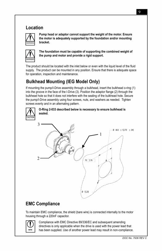
The product should be located with the inlet below or even with the liquid level of the fluid supply. The product can be mounted in any position. Ensure that there is adequate space for operation, inspection and maintenance.
LocationPump head or adaptor cannot support the weight of the motor. Ensure the motor is adequately supported by the foundation and/or mounting bracket.
The foundation must be capable of supporting the combined weight of the pump and motor and provide a rigid support.
Bulkhead Mounting (IEG Model Only)If mounting the pump/I-Drive assembly through a bulkhead, insert the bulkhead o-ring (1) into the groove in the face of the I-Drive (3). Position the adaptor flange (2) through the bulkhead hole so that it does not interfere with the sealing of the bulkhead hole. Secure the pump/I-Drive assembly using four screws, nuts, and washers as needed. Tighten screws evenly and in an alternating pattern.
EMC ComplianceTo maintain EMC compliance, the shield (bare wire) is connected internally to the motor housing through a 220nF capacitor.
NOTE
Compliance with EMC Directive 89/336/EC and subsequent amending directives is only applicable when the drive is used with the power lead that has been supplied. Use of another power lead may result in non-compliance.
O-Ring 2-033 described below is necessary to ensure bulkhead is sealed.
CAUTION
Ø 68.3 ± 1[2.70 ± .04]
70 2.76
Ø 5[.20]
1
3
2

�0
DOC No: 7936 REV C
Pumping flammable fluids without a proper earthing connection may cause spontaneous ignition.
I-Drive Electrical Connection
Ensure that the pump motor is earthed. The pump may be electrically isolated from the motor depending on the mounting configuration. Some installations may need an earthing connection on the pump head.
Before starting any electrical installation work ensure that the main electrical supply is adequately isolated.
Electrical installation must be carried out by qualified personnel who are conversant with local electricity installation regulations.
Ensure that the voltage and frequency of the supply are correct for the motor being connected, and that the source is Class 2 or a Limited Power Source.CAUTION
Ensure that all electrical connections use a common earth ground to avoid hazardous ground loops.
Ensure that only power supplies having SELV specification are connected to the I-Drive.
CAUTION
Ensure that all associated equipment has a form of overcurrent protection. If a fuse is used see table below for recommendations.
CAUTION
The I-Drive does not have reverse-polarity protection. If the common (black) lead is connected to the positive terminal of the power supply the motor will be irreparably damaged.CAUTION
Power InThe main input power is 14 to 30 VDC from a Class 2 (SELV) source applied across the power in and common ground leads. This voltage must be maintained within the specified limits as the motor is loaded to its maximum current of 1.8A (Model - IMS) or 2.9A (Model - IEG.)
Ensure that the power supply voltage ripple is maintained below 5% peak to peak.
CAUTION
I-DrIve MoDel ProDuct coDe recoMMenDeD fuse
IMs DG-D42.H2 Accu GuArD P/n f1206B3r00fWtr
IeG DG-f61.G1 Accu GuArD P/n f0612D4r00fWtr

��
DOC No: 7936 REV C
I-Drive Electrical Connection (Continued)Control Signal InFor motors having 0 to 5 VDC or 4 to 20 mA speed control, when the lead is connected to a supply within the range the motor speed is proportional to the input. If the lead is connected to a greater input, the motor will run at its maximum speed. If the lead is connected to a lesser (or reverse polarity) input, the motor will stop.
Common GroundThe input voltage, the 0 to 5 VDC control input, and the tachometer output all use a common ground. It is possible that ground potential differences between the power supply, control voltage source and the frequency counter (if used) will be forced to the same ground reference when connected to the I-Drive. While not typical, in some cases large current flows can result or undesirable currents can flow through these devices’ ground wires if more than one device is connected to earth ground. Ensure only one earth ground is used.
Isolated GroundThe motor common (black) wire is isolated from the motor housing. There is an internal connection between the motor housing and the cable shield (bare wire) which is a capacitive coupling (220nF, 63V) with the common (black) wire. If the black lead is connected to the shield, EMC will not be affected. This can be done at the customer input end of the cable.
Using The Tachometer Output The tachometer output can be monitored using a frequency counter. The tachometer output is 0-5V square wave pulse that occurs twice per pump drive revolution. The frequency range is 0-200Hz. To convert the tachometer output to rpm, multiply the frequency by 30.
Inadvertent connection of the tachometer output (green) wire to ground or the supply voltage can cause damage to the drive. If the tachometer is not used, trim and insulate the green lead.CAUTION
DO NOT reverse the direction of rotation of the drive until the drive has come to a complete stop. Reversing the direction while the drive is still turning may damage the motor.CAUTION
NOTE
Inadvertent grounding of the forward/reverse (orange) wire will cause the drive to operate in reverse. If reverse operation is not required, trim and insulate the orange lead.
COMMON
SHIELD
HOUSING
220nF63VDC
Forward/Reverse OperationThe direction of fluid flow can be changed by connecting the orange wire to ground. For FORWARD flow, make NO CONNECTION to the orange wire. For REVERSE flow, connect the orange wire to GROUND.

��
DOC No: 7936 REV C
123
5
4
6
123
5
4
6
MODEL IMS
MODEL IEG
Lead Function Color 0-5 VDC4-20mA Control
Manual Control
1 Power In Red +24 VDC, Class 2 (SELV)
2 Common Black Isolated from motor housing
3 Control Signal In White 0-5 VDC or 4-20mA potentiometer
4 Tachometer Out Green 5 V square wave-2 pulses per revolution
5 FWD/REV Orange Forward (float and insulate), Reverse (ground)
6 Shield -- Connected to housing
I-Drive Lead Wire Assignments
The 0-5 VDC Control Signal In is protected to withstand -30 to +30 V applied to it. Above 6 V and below 0 V the impedance is greater than or equal to 10 kOhm. Within the 0-6 V input range, the input impedance is 30.6 kOhm.NOTE

��
DOC No: 7936 REV C
Flow rate should always be adjusted by controlling motor speed where possible. Ensure that overpressure does not occur in the discharge pipe. NEVER throttle flow by an inlet valve.
Starting or running the pump with the discharge valve closed will overload the motor resulting in overpressure in the discharge pipe.
Post Start-up ChecksOnce the pump has started, carry out the following checks:1. Check that the pump and motor operate smoothly and are free from vibration.2. Check the inlet and discharge fittings are free from leaks.
Operation
Start-up ProcedureBefore starting the pump ensure that any valves in the inlet or discharge lines are open and that any inlet filters are clean and free from obstruction.
1. Set the external control signal input to minimum value (0 VDC or 4mA or turn the manual control fully anti-clockwise.)
2. Set the power supply (24 VDC to max 30 VDC) to ON. With the control input set to 0 VDC, 4mA or the manual control turned fully anti-clockwise, the pump will show a nominal 40mA to 70mA current draw and will not turn.
3. Adjust the control signal input to the required level. Current demand will rise and fall as the pump load and speed varies.
Once started the pump should prime if it has not already been filled with fluid. If the pump fails to prime, stop the pump and fill the pump head with liquid.
Shut-down ProcedureSwitch off the I-Drive by first setting the external control signal input to the minimum value, then switch off the power supply. Check that the unit runs down in a steady manner. Close the inlet and discharge valves. Drain the pump if it is to be shut-down for long periods or installed in areas where the liquid may freeze. Refer to the Maintenance section for instruction on draining.
Extended periods of dry running may result in permanent damage to the pump and may cause surface temperature to exceed the operating temperature of the pump. Ensure that the pump head temperature does not exceed the flash point temperature of the fluid or area. Shut down pump for a no fluid condition. Shut down the pump for a no flow condition.
CAUTION
Ensure the pump head temperature does not exceed the flash point temperature of the fluid or area.
Two-wire mode is available on the 0 to 5 VDC control models. To run the motor in two-wire mode, the control (white) wire can be connected to the positive supply (red) wire. The motor will run at its maximum speed. The speed control will not be damaged if the applied voltage is within +/-30 VDC of the common (black) wire, though maximum speed is achieved at +5 VDC or higher, and the motor will stop if 0 VDC or lower is applied.
NOTE

��
DOC No: 7936 REV C
The drive enclosure is rated to IP55. The enclosure rating is maintained by using the manual control cover screw and seal. After adjustment, these components must be replaced and secured to the proper torque in order to maintain the enclosure rating and protection of internal drive controller.
Manual Control Adjustment
Manual Control AdjustmentIf your drive is equipped with the manual control option, the speed of the drive is controlled by local adjustment of an internal potentiometer. To adjust the speed set point:1. Remove and retain the M3 cover screw (1) using a small screwdriver. 2. Remove and retain the screw seal (2). 3. Insert a small screwdriver (3) into the access hole and engage the potentiometer
adjustment screw. To increase speed, rotate the adjustment clock-wise. To decrease speed, rotate the adjustment counter-clockwise. The potentiometer is equipped with a slip coupling which will allow the user to continue to turn the adjustment screw after maximum and minimum speed is reached.
4. When adjustment is complete, replace the screw seal (2) and (1) the cover screw. Tighten the cover screw to 6 in-lb (678 mNm).
CAUTION
1
2
3

��
DOC No: 7936 REV C
MaintenanceExcessive wear to the pump can result in driven magnet rub on the magnet cup. This can generate high surface temperatures or degrade the capability of the pressure boundary. Remove the pump from service and replace or repair if pump performance degrades significantly or the pump becomes noisy.
Ensure that heavy deposits of dust are not allowed to accumulate. Clean the pump periodically.
The pump cannot be drained completely, a certain amount of liquid will remain in the magnet cup area. Ensure that the pump is either flushed with a suitable flushing agent or precautions are taken against the effect of any remaining liquid during servicing. When the pump has been handling flammable, toxic or hazardous fluid, the pump internals must be properly decontaminated by suitably qualified personnel. The Material Safety Data Sheet for the pumped liquid must be referred to for correct procedures and precautions to be followed when handling the liquid.
Micropump I-Drive motors are designed to be maintenance free and, apart from manual speed control models, require no adjustments. To ensure the motor or pump/motor assembly retains optimum performance maintain the fluid circuit to keep filters clean and prevent abrasive solids from passing through the pump.
A program that includes periodic monitoring of your Micropump product is recommended to provide timely detection and assessment of any problem.
NOTE
Magnet DecouplingThe I-Drive pump/motor combinations do not decouple. If pump load becomes excessive, current limiting in the controller prevents motor overload. Additional protection is provided by a thermal sensor which shuts down the drive if the housing temperature exceeds 80°C (176°F).

��
DOC No: 7936 REV C
Fault IsolationIf the I-Drive does not meet its design performance or fails to operate correctly, refer to the following tables for assistance in identifying the cause and remedy:
MOTOR WILL NOT OPERATE
Cause RemedyNo power to motor. Ensure proper voltage has been applied to motor power leads.
Check leads to ensure no short circuits are present.
Control Input lead is shorted. Clear and isolate Control Input lead from Tachometer Out lead. Clear and isolate Control Input lead from Common lead.
No Control Input applied. Ensure proper control input is applied to Control Input lead.If manual control I-Drive, adjust potentiometer clockwise.Ensure control power supply common is connected to the Common lead.
Thermal Limit is active. Turn off motor and wait for temperature to cool below 70°C (158°F). NOTE: If power voltage and control signals are present, motor will automatically restart when temperature is reached.Reduce motor load conditions and/or improve cooling of motor housing if persistent limit occurs.
Motor has been damaged. Contact your Micropump Distributor or contact Micropump directly for replace-ment product.
CYCLIC NOISE OR VIBRATIONS
Cause RemedyLoose motor mounting bolts. Tighten motor mounting bolts.
Foundation not rigid. Relocate motor.
Pump loose on motor. Tighten pump mounting bolts.
Pump is worn. Replace or repair pump.
Tachometer Out lead is shorted to FWD/REV lead.
Clear and isolate Tachometer Out lead from FWD/REV lead.
NO TACHOMETER SIGNAL
Cause RemedyNo power to motor. Ensure proper voltage has been applied to motor power leads.
Check leads to ensure no short circuits are present.
Improper wiring. Check that the Tachometer Out lead is connected to the positive input of the frequency counter.Check that the common lead of the frequency counter is connected to the motor Common lead.Check leads to ensure no short circuits are present.
Motor is stopped. Ensure proper voltage has been applied to motor power leads Ensure proper control input is applied to Control Input lead.If manual control I-Drive, adjust potentiometer clockwise.Ensure control power supply common is connected to the Common lead.
MOTOR RUNS IN THE WRONG DIRECTION
Cause RemedyFWD/REV lead is shorted to Common lead.
Clear and isolate FWD/REV lead from Common lead. Check leads to ensure no short circuits are present.
Execution of troubleshooting steps, determination of root cause and corrective actions should be performed by a skilled maintenance person.

��
DOC No: 7936 REV C
All Dimensions in mm.[inch]
Technical Specification
Not all possible configurations are shown. Contact your local Micropump distributor or contact Micropump directly for additional versions.
I-Drive
Model IMS
Product Code DG-D42.H2
Speed Range 500 to 6000 rpm
Typical No-Load Speed (24 VDC Input / 5 VDC Control / 25°C Ambient)
6000 rpm
Speed @ Rated Torque 3500 rpm @ 56 mNm (8 oz-in)
Input Voltage Range 14 to 30 VDC
Max Full-Load Current @ Nominal Voltage(25°C Ambient)
1.8A @ 24 VDC
Speed Control 0 to 5 VDC / 4 to 20mA / Manual
Tachometer Out 0 to 5 VDC square wave - 2 pulse per revolution
Thermal Shutdown 80°C (176°F)
Thermal Restart 70°C (158°F)
Storage Temperature -40 to +85°C (-40 to +185°F)
Maximum Ambient Operating Temperature 40°C (104°F)
Reversible Yes
Enclosure Rating IP55
Weight 0.37 kg (.82 lbs)
52.4 2.06
71 2.80
44.4 1.75
30.5 [0.60]
48.3 [0.95]
Ø4.2 [Ø0.08]
Model IMS
NOTE
NOTE

��
DOC No: 7936 REV C
57.7 2.27
5 .20
88.9 3.50
70 2.76
70 2.76
Ø 5 .20
I-Drive
Model IEG
Product Code DG-F61.G1
Speed Range 500 to 5500 rpm
Typical No-Load Speed (24 VDC Input / 5 VDC Control / 25°C Ambient)
5500 rpm
Speed @ Rated Torque 3500 rpm @ 106 mNm (15 oz-in)
Input Voltage Range 14 to 30 VDC
Max Full-Load Current @ Nominal Voltage(25°C Ambient)
2.9A @ 24 VDC
Speed Control 0 to 5 VDC / 4 to 20mA / Manual
Tachometer Out 0 to 5 VDC square wave - 2 pulse per revolution
Thermal Shutdown 80°C (176°F)
Thermal Restart 70°C (158°F)
Storage Temperature -40 to +85°C (-40 to +185°F)
Maximum Ambient Operating Temperature 40°C (104°F)
Reversible Yes
Enclosure Rating IP55
Weight 0.37 kg (.82 lbs)
Model IEG

��
DOC No: 7936 REV C
85.5 3.37
55 2.17
50.8 2.00
40.8 1.61
5 .20
77.9 3.07
44.5 1.75
126.4 4.97
61.9 2.44
4.7 .19
Model IMS Mounting Bracket
Model IEG Mounting Bracket

�0
DOC No: 7936 REV C
Notes

��
DOC No: 7936 REV C
Micropump, Inc.A Unit of IDEX Corporation1402 NE 136th AvenueVancouver, WA 98684 USATel: +1 (360) 253-2008Fax: +1 (360) 253-2401E-mail: [email protected]: www.micropump.com
Micropump LimitedA Subsidiary of Micropump, Inc.Howard Road, Eaton SoconSt Neots, Cambridgeshire PE19 8ET EnglandTel: +44 (0) 1480 356900Fax: +44 (0) 1480 356920
To purchase pumps, parts or receive further information contact your local Micropump distributor or contact Micropump directly.
no. 3798
“MIcroPuMP” AnD tHe MIcroPuMP loGo Are trADeMArKs of MIcroPuMP, Inc.
Your Micropump Distributor Is:
A3997A8475
ISO 9001ISO 14001
Micropump, Inc.