installation / operation - fairfield...
TRANSCRIPT

Installation / Operation Select™ 3/G7200 Fleet Dispensers
920812 Rev L

READ THIS MANUAL BEFORE YOU BEGIN Dispensers have both electricity and a hazardous, flammable, and potentially explosive liquid. Failure to follow the below precautions and the Warning and Caution instructions in this manual may result in serious injury or death. Read every tag attached to the dispenser before commencing installation. Follow all rules, codes, and laws that apply to your area and installation.
SAFETY PRECAUTIONS - INSTALLATION AND MAINTENANCE Always make sure ALL power to the dispenser (motors and electronic head) is turned OFF before you open the dispenser cabinet for maintenance. Physically lock, restrict access to, or tag the circuit breakers you turn off when servicing the dispenser. If applicable, be sure to trip (close) the emergency valve(s) under the dispenser BEFORE beginning maintenance.
Make sure that you know how to turn OFF power to the dispenser and submersible pumps in an emergency. Have all leaks or defects repaired immediately.
EQUIPMENT PRECAUTIONS Be sure to bleed all air from the product lines of remote dispensers and prime suction pumps before dispensing product, otherwise, damage to the equipment may occur. Always use the approved method for lifting the dispenser. Never lift by the nozzle boot, sheet metal, etc., otherwise equipment damage or personal injury may occur.
USE ONLY GENUINE PARTS For product liability to be valid, no changes may be made to the equipment without the written consent of Wayne.
REGISTRATION OF SITE AND HOW TO CONTACT WAYNE The equipment used at this site must be registered prior to contacting Wayne for warranty service. Sites can be pre-registered prior to installation by a Wayne Authorized Service Organization (ASO) via the on-line registration system OR through completing the Section 1 portion of the form, at the end of this manual, and sending it to Wayne (for non-ASOs). Pre-registration of a site helps to expedite warranty service in case it is needed. Please allow 2-3 days after receipt of the information for pre-registration. Final registration, which requires all of the information pertaining to the site including Start-Up date and equipment serial numbers, must be completed within 7 days of the completion of the Start-Up using the same aforementioned methods.
Trouble with the installation of this product should be referred to your Wayne® ASO. An ASO with a technician number can receive assistance by calling Wayne at Technical Support at:
1-800-926-3737
Customers, Installers or Distributors who are not an ASO, needing help with the operation or installation of this product, should contact the Wayne Help Desk at:
1-800-289-2963 OR [email protected]
INDICATORS AND NOTATIONS Danger indicates a hazard or unsafe practice which, if not avoided, will result in severe injury or possibly death.
Warning indicates a hazard or unsafe practice which, if not avoided, may result in severe injury or possibly death.
Caution indicates a hazard or unsafe practice which, if not avoided, may result in minor injury.
Important information to consider, otherwise, improper installation and/or damage to components may occur.
NOTE:
DANGER
WARNING
CAUTION
DANGER

920812 Rev L 7/2014
Table of Contents
Title Page
1 INTRODUCTION……………………………………..………………..………………………………. 1
1.1 Dispensers Covered………………………………………………………………………..…. 1
1.2 Model Description……………………………………………………………………………… 2
1.2.1 Enhanced Capacity Models…………………………………….…………………… 2
1.2.2 Super High Capacity Models…………………………………………..…………… 3
1.2.3 Ultra High Capacity Dispenser Models…………………………………….……… 4
1.2.4 Satellite Dispenser Models……………………………………………..…………… 5
1.3 Model Designation Format…………………………………………………………….…..…. 6
1.4 Technical Information……………….………………………………………………………… 7
2 SITE DESIGN & PREPARATION…………………………………………………………………… 11
2.1 Local, State, and Federal Codes……………………………………………………………… 11
2.2 Safety Precautions………………………………….…………………………………………. 12
2.3 Ethanol Installations…………………………………………………………………..……….. 13
2.4 Existing Installations………………………………………..……………………….………… 13
2.5 Island Construction, Dispenser Anchoring, and Piping………….……………..….……… 13
2.6 Suction Pump Installations…………………………………..…………………….…………. 14
2.6.1 Suction Pumps – General…………………………………………………………… 14
2.6.2 Suction Pumps with Aboveground Tanks………………………………..……….. 14
2.6.3 Suction Pump Check Valves………………………………………….…...……….. 15
2.6.4 Connecting More Than One Suction Pump to a Tank…………………………… 15
2.7 Remote Dispenser Applications…………………………………………………..………… 16
3 INSTALLATION………….…………………………………………………………………..………. 17
3.1 Equipment Inspection ………………………………………………………..…………….. 17
3.2 Lifting and Installing the Dispenser ……………………………………………………….. 17
3.3 Electrical Wiring ……………………………………………………………..…………….. 18
3.3.1 General………………………………………………………………..……………… 18
3.3.2 Electrical Termination Descriptions – All Dispensers……………....…………… 18
3.3.3 Electrical Termination Descriptions – Master Dispenser Models……………….. 20
3.3.4 Electrical Termination Descriptions – Pulse Output Interface Option….….…… 21
3.3.5 Circuit Breakers & Emergency Electrical Disconnect……………………………. 22
3.3.6 Pump Motor Voltage Setting………………………………………………..……… 23
3.3.7 Grounding …………………………………………………………………………... 23
3.3.8 Wiring ………………………………………………………………………….…….. 24
3.3.9 Conduit ……………………………………………………………………………… 25
3.4 Hose and Accessories Installation …………………………………………..……..……… 26
3.4.1 General……………………………………………………………………….……… 26
3.4.2 Vapor Recovery Nozzles …………………………………………………………. 26

920812 Rev L 7/2014
Table of Contents (continued)
Title Page
4 START-UP……………………………………………………………….…………………………… 27
4.1 Initial Checkout …………………………………………….…………………………………. 27
4.2 Configuring the Dispenser Software…..………………….………………………………… 28
4.2.1 General ……………………………………………………………………………… 28
4.2.2 Making Configuration Changes…………………………………………………….. 28
4.2.3 Configuration Start Up (Units without Price Displays)……………………………. 29
4.2.4 Configuration Start Up (Units with Price Displays)………………………………. 30
4.2.5 Set the Pulse Output Resolution ………………………..………………………… 34
4.3 Operating Units w/ Pulse Output Interface Before Control System is Operational….… 36
4.4 Priming Suction Pumps………………………………………………………………..…….. 37
4.5 Bleeding Product Lines (Remote Dispensers) …………..………………………….…….. 38
4.6 Initial Delivery………………………………………………………………………………….. 38
4.7 Meter Check (Calibration) – Enhanced Capacity & Super High Capacity…………….… 39
4.7.1 General ……………………………………………………………………….…….. 39
4.7.2 Accuracy Verification – Enhanced Capacity & Super High Capacity ………… 39
4.7.3 Calibration Procedure – Enhanced Capacity & Super High Capacity ………... 40
4.8 Meter Check (Calibration) – Ultra High Capacity Models……………………………..…. 42
4.8.1 General ……………………………………………………………………………… 42
4.8.2 Accuracy Verification – Ultra High Capacity……………………………………… 42
4.8.3 Calibration Procedure – Ultra High Capacity……….…………………………….. 43
4.9 Pulley Alignment (Suction Pumps) …………………………………………………….… 44
4.10 Belt Adjustment (Suction Pumps) ………………….…………………………………..… 44
4.11 Compact Pumping Unit Adjustment …………………………………………………….…. 46
4.12 Fluorescent Lights ………………………………………………………………………….. 47
4.13 Voltage Test………………………………………………………………………………..…. 47
4.14 Complete Installation……………………………………………………………………..….. 47
4.15 Complete Start-Up Report ……………………………………………………………..….. 47
5 OPERATION …………………….……………………………………………………………….… 49
5.1 Safety Items You Should Know ………………………………………………………….… 49
5.1.1 Portable Tanks and Containers ………….…………………………………….…. 50
5.1.2 Health Note……………………………………………………….………………….. 50
5.2 Dispenser Operation …………………………………………………….………………….. 50
5.3 Status Display Messages ……………………………………………..………………….. 51
5.4 Electromechanical Totalizers ………………………………………………………………. 52
5.5 Dispenser Statistics & Diagnostics ………………………………………………………… 52
5.5.1 General ……………………………………………………………………………… 52
5.5.2 Password Protection …………………………………………….…………………. 53
5.5.3 Changing Your Passwords …………………………………….………………….. 53
5.5.4 Viewing the Electronic Totalizers…….………………………..………………….. 55

920812 Rev L 7/2014
Table of Contents (continued) Title Page
6 MAINTENANCE ………………………………………………………………….…………..…… 59
6.1 Preventive Maintenance …………………….………………………….…………………… 59
6.2 Strainer/Filter – Enhanced Capacity and Super High Capacity ………………………… 59
6.3 Filters – Ultra High Capacity Models ………………………………….…………………… 60
6.4 Cleaning and Corrosion Protection Instructions …………………….……………………. 60
6.5 Meter Maintenance Issues …………………………………………..……………………. 61
6.6 Fluorescent Light Bulb Replacement ………….………………………………………….. 61
6.7 How to Get Service on Your Pump …………….………………………………………….. 61
APPENDIX A - DIMENSIONS & BASE LAYOUTS …………………………………………………… 63
3/G7201P/2JK/W Single Suction Pump - Island ..………………….…………………… 64
3/G7207P/2JKR/W Single Suction Pump - Lane………..………………………………… 64
3/G7202P/2JK Twin I Suction Pump - Island ……………………….…………………… 65
3/G7207P/2JK Twin I Suction Pump - Lane …….……..………………………………… 65
3/G7203P/28JK/W Twin II Suction Pump – Island …………………..………………….. 66
3/G7208P/28JK/W Twin II Suction Pump – Lane……………..………………………….. 66
E3 or 3/G7201D/2GJK Single Remote Dispenser – Island ……………………………. 67
E3 or 3/G7207D/2GJKR Single Remote Dispenser – Lane………………………………. 67
3/G7242D/2GJK Twin I Remote Dispenser – Island ………………….…………………. 68
3/G7247D/2GJK Twin I Remote Dispenser – Lane…………………….………………… 68
E3/G7202D/2GJK Twin I Remote Dispenser – Island …………………………………. 69
E3/G7207D/2GJK Twin I Remote Dispenser – Lane …………………………………… 69
E3 or 3/G7203D/28GJK Twin II Remote Dispenser – Island ………….………………… 70
E3 or 3/G7208D/28GJK Twin II Remote Dispenser – Lane ………..…………………. 70
3/G7221P/8JK Super High Capacity Single Suction Pump – Island ………..………….. 71
3/G7227P/8JKR Super High Capacity Single Suction Pump – Lane ………..…………. 71
3/G7221D/GJK Super High Capacity Single Remote Dispenser – Island….………….. 72
3/G7227D/GJKR Super High Capacity Single Remote Dispenser – Lane………………. 72
3/G7227D/GJKMR Super High Capacity Single Master Remote Dispenser – Lane….. 73
3/G7227D/GJKM Super High Capacity Twin I Master Remote Dispenser – Lane…….. 74
3/G7227D/GJK Super High Capacity Twin I Remote Dispenser – Lane………………… 75
3/G7228D/GJKLM Super High Capacity Single Master Remote Dispenser & Satellite Combination– Lane…………………………………………………………. 76
3/G7231D/GJK Ultra High Capacity Single Remote Dispenser – Island……………….. 77
3/G7237D/GJKMR Ultra High Capacity Single Master Remote Dispenser – Island.…… 77
3/G7232D/GJK Ultra High Capacity Twin I Remote Dispenser – Island………………… 78
3/G7237D/GJKM Ultra High Capacity Twin I Master Remote Dispenser – Lane….….. 78
3/G7236D/GJKMR Ultra High Capacity Twin I Master Rem. Disp, Sing-Sided – Lane….78
3/G7233D/GJK Ultra High Capacity Twin II Remote Dispenser – Island ……..……… 79
3/G7238D/GJKM Ultra High Capacity Twin II Master Remote Dispenser – Lane……… 79
3/G7234D/GJKMR Ultra High Capacity Twin II Master Remote Dispenser – Island…… 79
3/G7238D/GJKLM Ultra High Capacity Single Master Remote Dispenser & Satellite Combination – Lane ………………………………………………………. 80

920812 Rev L 7/2014
Table of Contents (continued)
Title Page
Side View (Nozzle Side) – All Select Models (except Satellites) ………………………. 81
3/G7007/JKLR Single Satellite Dispenser - Lane ...................................................... 82
3/G7008/JKL Twin Satellite Dispenser - Lane ......................................................... 83
3/G7037/JKLR Ultra High Capacity Single Satellite Dispenser – Lane ……………….. 84
3/G7038/JKL Ultra High Capacity Twin Satellite Dispenser - Lane ............................ 85
3/G7039/JKLR Ultra High Capacity Twin Satellite Dispenser – Lane, Single-Sided….... 85
APPENDIX B – ELECTRICAL RATINGS & WIRING DIAGRAMS…………………………………... 87
Electrical Ratings………………………………………………………………………………. 87
3/G7201P/2JK/W Single Suction Pump - Island..……..……………………………………. 88
3/G7207P/2JKR/W Single Suction Pump - Lane………..………………………………… 88
3/G7202P/2JK Twin I Suction Pump - Island ………….………………………………….. 88
3/G7207P/2JK Twin I Suction Pump - Lane…….……..………………………………….. 88
3/G7203P/28JK/W Twin II Suction Pump – Island ………………………………………. 89
3/G7208P/28JK/W Twin II Suction Pump – Lane …………..……………………………. 89
E3 or 3/G7201D/2GJK Single Remote Dispenser – Island………….…………………… 90
E3 or 3/G7207D/2GJKR Single Remote Dispenser – Lane……………………………… 90
3/G7242D/2GJK Twin I Remote Dispenser – Island………………………………………. 90
3/G7247D/2GJK Twin I Remote Dispenser – Lane………………………………………… 90
E3 or 3/G7202D/2GJK Twin I Remote Dispenser – Island……………………………….. 90
E3 or 3/G7207D/2GJK Twin I Remote Dispenser – Lane…………………………………. 90
3/G7221D/GJK Super High Capacity Single Remote Dispenser – Island………………. 90
3/G7227D/GJKR Super High Capacity Single Remote Dispenser – Lane………………. 90
3/G7227D/GJK Super High Capacity Twin I Remote Dispenser – Lane…….………….. 90
E3 or 3/G7203D/28GJK Twin II Remote Dispenser – Island……………………………… 91
E3 or 3/G7208D/28GJK Twin II Remote Dispenser – Lane………….………………….. 91
3/G7221P/8JK Super High Capacity Single Suction Pump – Island……………………. 92
3/G7227P/8JKR Super High Capacity Single Suction Pump – Lane…………………… 92
3/G7227D/GJKMR Super High Capacity Single Master Remote Dispenser – Lane….. 93
3/G7227D/GJKM Super High Capacity Twin I Master Remote Dispenser – Lane…….. 94
3/G7228D/GJKLM Super High Cap Single Master Rem Disp & Sat Combo– Lane…… 95
3/G7231D/GJK/W3 Ultra High Capacity Single Remote Dispenser – Island ..………… 96
3/G7237D/GJKMR/W3 Ultra High Capacity Single Master Remote Dispenser – Lane.. 96
3/G7232D/GJK/W3 Ultra High Capacity Twin I Remote Dispenser – Island…….…….. 97
3/G7237D/GJKM/W3 Ultra High Capacity Twin I Master Remote Dispenser – Lane…. 97
3/G7233D/GJK/W3 Ultra High Capacity Twin II Remote Dispenser – Island..…………. 97
3/G7238D/GJKM/W3 Ultra High Capacity Twin II Master Remote Dispenser – Lane… 97
3/G7234D/GJKM/W3 Ultra High Capacity Twin II Master Remote Dispenser - Lane, Single-Sided ..………………………………………………………………………….. 97
3/G7236D/GJKM/W3 Ultra High Capacity Twin I Master Remote Dispenser – Lane, Single-Sided…………………………………………………………………………… 97
3/G7238D/GJKLM/W3 Ultra High Capacity Single Master Remote Dispenser & Satellite
Combination– Lane…….……………………………………………………………… 98

920812 Rev L 7/2014
Table of Contents (continued)
Title Page
APPENDIX C – PULSE OUTPUT INTERFACE WIRING DIAGRAM……………………………….. 99
C.1 Pulse Output Interface Wiring Diagram …………………..……………………………. 99
C.2 Pulse Output Interface Board Layout ……………………………………………………… 100
APPENDIX D – CURRENT LOOP INTERFACE ……….…………………………………..….……. 101
D.1 Point-to-Point Dispenser to Fusion HyperPIB Wiring ……………………………..……. 101
D.2 Point-to-Point Dispenser to Fusion UDB Replacement Wiring………….………………. 102
D.3 Point-to-Point Dispenser to Data Distribution Cabinet Wiring ……………………..……. 103
D.4 Wiring Using One Data Distribution Cabinet (Up to 16 dispensers) ……………..……. 104
D.5 Wiring Using Two Data Distribution Cabinets (Up to 24 dispensers)……………………. 105
APPENDIX E – DISPENSER SOFTWARE CONFIG, STATISTICS, & DIAGNOSTICS………..… 107
E.1 General…………………………………………………………………………………………. 107
E.2 Entering Functions and Statistics ………………………………………………………….. 107
E.3 IRC Commands ……………………………………………………………………………… 108
E.4 Changing Sub-function Values………………………………………………………………. 109
E.5 Resetting Totals………………………………………………………………………………. 110
E.6 Exiting Functions …………………………………………………………………………… 110
E.7 Exiting Statistics ……………………………………………………………………………. 110
E.8 Quick Exit from Functions and Statistics ………………………………………………….. 111
E.9 Dispenser Side & Nozzle Identification ……………………………………………………. 111
E.10 Pulse Output Interface Option Settings …………………………………………………… 113
E.11 List of Statistics……….………………………………………………………………………. 114
E.12 Meter Number Assignments ………….…..……………………………………………….. 116
E.13 Configuration Functions …………………………………………………………………… 117
E.14 Configuration Sub-Function default Settings for Non-UHC Models …..……………… 130
E.15 Configuration Sub-Function default Settings for UHC Models ………..………………… 131
APPENDIX F – LOCAL AUTHORIZE / STANDALONE OPERATION …………………………….. 133
F.1 General ……………………………………………………………………………………… 133
F.2 Placing the Dispenser into Standalone Operation ……….……………………………… 134
APPENDIX G – WEIGHTS & MEASURES MODE & TEMPERATURE COMPENSATION……… 137
G.1 Weights & Measures Mode .………………………………………………………….……. 137
G.2 Weights & Measures Mode – Temp Comp Data…...…….…………………………..…… 141
G.3 Temp Comp Test Mode ……………………………………………………………………. 142
APPENDIX H – iX FLEET ………….………………………………………………………………...… 143
H.1 General……..………………………………………………………………………………..… 143
H.2 Power Requirements……………..……………………….…………………………………. 143
H.2 Ethernet Connection……………………………………………………………………….…. 143

920812 Rev L 7/2014
Table of Contents (continued)
Title Page
APPENDIX I – TEMPLATES ………….……………………………………………………………....… 149
I.1 Select High Capacity and Super High Capacity Models (Servterm 6+)…….…….…..… 149
I.2 Select Ultra-High Capacity Models (Servterm 6+)….……………………………….…..… 150
I.3 Select High Capacity and Super High Capacity Models - Gallons…..…………..……… 151
I.4 Select Ultra-High Capacity Models - Gallons……...………………….……………………. 152
I.5 Select High Capacity and Super High Capacity Models - Liters……………..………..… 153
I.6 Select Ultra-High Capacity Models - Liters…………………………………...……………. 154
APPENDIX J – ERROR CODES ………….………………………………………………………....… 155
Error Code List…………………………………………………………………………………………. 155
APPENDIX K – Internal Wiring & Connectors ….…..…………………………………………....… 159
K.1 Internal wiring – CPU (Non UHC models) ……………..………………..………………. 159
K.2 Internal wiring – CPU (UHC, 115 VAC Valve) ……….….………………..……………… 160
K.3 Internal wiring – CPU (UHC, 24 VDC Valve) …………….………………….…………… 161
K.4 Internal wiring – Displays …………………………………………………………………… 162
K.5 Internal wiring – Power for Remote Dispensers…….………………………..…………… 163
K.6 Internal wiring – Power for Suction Pumps …………….….……………………………… 164
K.7 Internal wiring – Pulse Output ……………….………….….…………………..………… 165
K.8 Internal wiring – Connectors ……………..…….……….….……………………………… 166
K.9 Internal wiring – iX Fleet ……………………..……………………………………………… 167
APPENDIX L – WARRANTY REGISTRATION …………….……………………………………....… 169
L.1 Warranty Registration Instructions ………………….……………………………………. 169
L.2 Warranty Registration Definitions …..……………………………………………..……… 169

920812 Rev L 7/2014 1
1 INTRODUCTION
1.1 Dispensers Covered This manual describes the installation and operation of the Wayne Select Series Electronic Registration Fleet Dispensers. Wayne Select dispensers are designated by the 3/G7200 model number series. Model descriptions are shown in Section 1.2. The model number suffix designations are defined in Section 1.3. Select dispensers may be installed and operated as a stand-alone unit or they may be controlled by a third party fuel control system. This manual provides installation and operation information for Select dispensers operating as stand-alone units. General information is provided for connecting to third party fuel control systems. It is also necessary to consult the applicable third party fuel control system documentation for installation and operation information and any necessary safeguards and warnings. Any questions concerning the installation and operation of the dispensers that are not covered in this manual should be referred to your authorized Wayne service personnel or Wayne Technical Support (1-800-926-3737) or [email protected].
NOTE: Terminology Used in This Manual
Dispenser(s): Generic term used to refer to any model in the Wayne Select Series.
Suction Pump(s): Models with self-contained pumping units installed in the dispenser hydraulic cabinet.
Remote Dispenser(s): Models utilizing a submersible pump in the tank to provide fuel to the dispenser.
Satellite Dispensers: Models that do not have their own meter, pumping units, or displays. Satellite hoses are supplied product from a “master” remote dispenser and provide an additional fueling point for that dispenser. Any fuel dispensed from the satellite hose is registered on the master dispenser to which it is connected. Satellite dispensers are typically mounted on the opposite side of the fueling lane from the related master dispenser to simplify filling vehicles with saddle tanks.
Enhanced Capacity: Suction pump and remote dispenser models with one Wayne iMeter measuring chamber per hose.
Super High Capacity (SHC): Remote dispenser models with two Wayne iMeter measuring chambers per hose for increased flow performance.
Ultra High Capacity (UHC): Remote dispenser models using a Liquid Controls® meter per hose for maximum flow performance.

2 920812 Rev L 7/2014
1.2 Model Description
1.2.1 Enhanced Capacity Models
TYPE SUCTION PUMPS REMOTE DISPENSERS
Island-Oriented Lane-Oriented Island-Oriented Lane-Oriented
Single
One Hose, One
Product
3/G7201P/2JK/W 3/G7207P/2JKR/W 3/G7201D/2GJK E3/G7201D/2GJK
3/G7207D/2GJKR E3/G7207D/2GJKR
Twin I
Two Hoses,
One Product
3/G7202P/2JK 3/G7207P/2JK 3/G7242D/2GJK 3/G7247D/2GJK
N/A N/A E3/G7202D/2GJK E3/G7207D/2GJK
Twin II*
Two Hoses,
Two Products
3/G7203P/28JK/W 3/G7208P/28JK/W 3/G7203D/28GJK E3/G7203D/28GJK
3/G7208D/28GJK E3/G7208D/28GJK

920812 Rev L 7/2014 3
1.2.2 Super High Capacity Models
TYPE STANDALONE
MASTER
MASTER/ SATELLITE*
Island-Oriented Lane-Oriented Lane-Oriented Lane-Oriented
Single Suction
One Hose,
One Product
3/G7221P/8JK 3/G7227P/8JKR N/A N/A
Single** Remote
One Hose*,
One Product
3/G7221D/GJK 3/G7227D/GJKR 3/G7227D/GJKMR 3/G7228D/GJKLM
Twin I Remote
Two Hoses,
One Product
N/A 3/G7227D/GJK 3/G7227D/GJKM N/A
NOTES:
* The Master/Satellite has a single master dispenser and a single satellite dispenser housed in the same cabinet. There is a lane-oriented nozzle on one side for the master and a lane-oriented nozzle on the other side for the satellite dispenser.
** Single SHC remote dispenser models with the Automatic Temperature Compensation option (model suffix “/C”) utilize two separate ½-populated duplex iMeters instead of the single fully populated duplex iMeter as shown.
KEY – Front View
Display
Duplex Meter (1 meter used)
Duplex Meter (both meters used)
Suction Pump and Motor
Strainer/Filter Assembly
Piping (inlet or discharge)
Satellite Solenoid Valve
Nozzle Boot (island)
Nozzle Boot (lane)
KEY – Base Layout View
Display
Nozzle Boot
Dispenser Inlet
Satellite Inlet
Satellite Outlet
On front view, the AC junction box is the opposite side than the view shown.

4 920812 Rev L 7/2014
1.2.3 Ultra High Capacity Dispenser Models
TYPE
UHC REMOTE DISPENSERS
Island-Oriented Lane-Oriented Lane-Oriented, 2 Nozzles Same Side (single-sided)
Single
One Hose, One Product
3/G7231D/GJK 3/G7237D/GJKMR N/A
Twin I
Two Hoses, One Product
3/G7232D/GJK 3/G7237D/GJKM 3/G7236D/GJKMR
Twin II
Two Hoses, Two
Products
3/G7233D/GJK 3/G7238D/GJKM 3/G7234D/GJKMR
Combo Single & Satellite
Two Hoses,
Two Products
N/A 3/G7238D/GJKLM N/A
KEY – Base Layout View
Display
Nozzle Boot
Dispenser Inlet
Satellite Inlet
Satellite Outlet
On UHC remote dispensers, on front view, AC junction box is on the opposite side than the view shown.
KEY – Front View
Display
Meter
Dual 800 Series Filters
Discharge Piping
Inlet and Manifold Piping
Satellite Dispenser Piping
Nozzle Boot (island)
Nozzle Boot (lane)
Note: All UHC models may be piped and wired as master dispensers with satellites; however, only lane-oriented models are recommended for use as masters so there is a clear correlation between which master and satellite nozzles go together.

920812 Rev L 7/2014 5
1.2.4 Satellite Dispenser Models
TYPE SHC SATELLITES
Lane-Oriented
Single
One Hose, One
Product
3/G7007/JKLR
Twin
Two Hoses,
Two Products
3/G7008/JKL
TYPE
UHC SATELLITES
Lane-Oriented Lane-Oriented, 2 Nozzles Same Side (single-sided)
Single
One Hose, One Product
3/G7037/JKLR N/A
Twin I
Two Hoses, Two
Products
3/G7038/JKL
3/G7039/JKLR
KEY – Base Layout View
Nozzle Boot
Satellite Inlet
On satellite dispensers, on front view, AC junction box is on the same side as the view shown.
KEY – Front View
Satellite Dispenser Piping
Nozzle Boot (lane)

6 920812 Rev L 7/2014
1.3 Model Designation Format Prefix / Main Body / First Suffix / Second Suffix X / ABCDEF / ZZZZZZZZ / YYYYYYYYYY
Prefix X Electronic & Hydraulic Configuration
3 iGEM
E3 iGEM for E85
/
Main Body
A Model Series
G Global
B 7 Select Electronic Fleet
C Model Style 0 Satellite Cabinet
2 Column Style
D Flow Rate Capacity
0 Standard & High Capacity
2 Super High Capacity
3 Ultra High Capacity
4 Standard & High Capacity – Max. Two-Hose Flow (Twin I remote dispenser only)
E Hoses, Products, & Nozzle Configuration
1 One Hose, One Product, Island-Oriented Nozzle
2 Two Hoses, One Product, Island-Oriented Nozzles
3 Two Hoses, Two Products, Island-Oriented Nozzles
4 Only available with “R” suffix. Two Hoses, Single-Sided, Two Products, Lane-Oriented Nozzles
6 Only available with “R” suffix. Two Hoses, Single-Sided, Two Products, Lane-Oriented Nozzles
7 Two Hoses (One Hose w/ “R” suffix), One Product, Lane-Oriented Nozzle(s)
8 Two Hoses, Two Products, Lane-Oriented Nozzles
9 Century & All Satellites; requires “R” suffix. Two Hoses, Single-Sided, Two Products, Lane-Oriented Nozzles
F Hydraulic System D Remote Dispenser
P Suction Pump
/
First Suffix
Z
Additional Model Designators
L Satellite – Super & Ultra High Capacity Models
M Master – Super & Ultra High Capacity Models
R Single-Sided Lane-Oriented Model
Standard
2 Enhanced Capacity (1” discharge. This suffix is not used on Super or Ultra High High Capacity models.)
8 Indicates model uses two ½-populated duplex iMeters
G Internal Filter (Remote disps. only – n/a on suction models)
J Explosion-Proof AC Junction Box
K Hose Hanger (eliminated w/ hose retractor & mast options)
Options
1 Price displays
C Automatic Temperature Compensation-Non UL
D3 HealyVac, Single or Twin-One Side
D4 HealyVac, Twin with Both Sides
H Pulse Output Interface
I Satellite In Use Indicator (Masters with Price Displays)
S Preset-12 button (uses sales/volume display)
Z 240VAC Operation of Electronic Register and Light
/

920812 Rev L 7/2014 7
Second Suffix
Y
Standard W No Solenoid on Suction Models (N/A on Twin I where
solenoid is std. Delete suffix if solenoid is desired as option.)
W3 UHC Models Only – 120 VAC solenoid valves, (standard on units starting 9/14/2009)
Options
D1 iX Fleet, RF Tags, 1 Sided
D2 iX Fleet, RF Tags, 2 Sided
D3 iX Fleet, Mag Cards, 1 Sided
D4 iX Fleet, Mag Cards, 2 Sided
D5 iX Fleet, Keypad, 1 Sided
D6 iX Fleet, Keypad, 2 Sided
D7 iX Fleet, HID-Prox Cards, 1 Sided
D8 iX Fleet, HID-Prox Cards, 2 Sided
D9 iX Fleet, HID-Indala Cards, 1 Sided
D10 iX Fleet, HID-Indala Cards, 2 Sided
H Internal Hose Retractor
J Hose Mast
K Electromechanical Totalizer Per Hose (Only applicable on Enhanced Capacity Twin I models. EMT per hose is std. on all other models.)
X xFlo meter (used for E85 hydraulic trees)
1.4 Technical Information
Application: For dispensing low viscosity petroleum fuels - diesel, including biodiesel blends up to 20%; kerosene; gasoline, including standard oxygenated blends; AvGas; and Jet Fuel (check with fuel supplier for any metal flow path restrictions for AvGas and Jet Fuel, you must install the appropriate filters, water separators, etc. needed for the fuel type being used.) - from aboveground or underground storage tanks in applications where only volume measurement is required. Dispensers with the “E” Prefix utilize nickel-plating, hard anodizing, stainless steel, special elastomers and a special fuel filter. While standard dispensers are Listed to handle Ethanol products up to an E10 blend, “E” prefix dispensers are Listed for use with products up to E85. Use hanging hardware rated for the available fuel type dispensed. Note: Dispenser not Listed by a nationally recognized testing laboratory (NRTL) for Biodiesel (over 5%), AvGas, or Jet Fuel.
Performance: Enhanced Capacity: Up to 22 GPM (83 LPM) maximum test rate at discharge outlet. Twin I suction pump model is 22 GPM per one hose operating, or 12 GPM (45 LPM) per hose with both operating. Super High Capacity (SHC): Up to 36 GPM (136 LPM) maximum test rate at discharge outlet. For Twin I SHC model, maximum test rate is with one hose operating at a time. Ultra High Capacity (UHC): Up to 60 GPM (227 LPM) maximum test rate at discharge outlet (total of both Master & Satellite hoses in use at same time). Important: Actual flow rates will depend upon the installation conditions, product dispensed, dispenser accessories, and for remote dispensers, the size of the submersible pump.
Electronic Head: Wayne iGEM electronics platform. Controls dispenser operation. Provides user operating messages, transaction limit controls, error monitoring, enhanced diagnostics. Allows software uploads/downloads via a PC. Infrared remote control allows configuring settings, reading totalizers, and accessing diagnostic tools. 120/240VAC 50/60 Hz operation. (Note: Light is only 120 VAC std. - 240VAC option required for 240VAC operation.)

8 920812 Rev L 7/2014
Liquid Crystal Displays:
Backlit 1” (2.5 cm) six-digit Volume and Total $ displays (Total $ for /1 option) and ½” (1.3 cm) four-character status display per hose (Price for /1 option). Displays each side of cabinet, except models with lane-oriented nozzle boots only display on corresponding nozzle boot side. Configurable 0-4 digits to right of decimal. Programmable gallons or liters. In event of power loss, remain visible for approximately 15 minutes.
Totalizers: 7-digit electromechanical non-resettable totalizer per product. One non-resettable and one resettable electronic 6-digit totalizer per hose. Electronic totalizers display on volume display by using infrared remote control.
Light: Light in electronic head provides backlighting for liquid crystal displays and illuminates product identification panels. 120VAC 60 HZ operation. Optional 240VAC 50/60 Hz operation.
Fuel Control System Interfaces:
Wayne dispenser US Current Loop protocol. Optional pulse output interface.
Meter: Enhanced Capacity and Super High Capacity Models: Wayne 2-piston, positive displacement iMeter with integral intelligent pulser. E85 models utilize Xflo meter. Electronic calibration. Ultra High Capacity Models: Liquid Controls M-5 positive displacement rotary meter with Wayne optical pulser. Electronic calibration.
Pumping Unit: Suction pump models. Wayne Compact Pumping Unit (CPU). Belt-driven, positive displacement rotary gear pump with integral centrifugal air separator. Not available on UHC or E85 models.
Motor: Suction pump models. 1 HP, continuous duty motor. 120/240VAC, 50/60 Hz, with thermal overload. Adjustable V-link belt connects to the pump pulley.
Junction Boxes: Explosion-proof AC junction box standard for electronic head, light, suction pump, and submersible connections. Additional explosion-proof junction box supplied with pulse output interface option for third party control system wire terminations.
Strainer: Enhanced Capacity and Super High Capacity Models: 120-mesh; removable for cleaning. Ultra High Capacity Models: No strainer is provided. See filter section. Disposable strainer canisters are available as an option replacing filters.
Filter: Enhanced Capacity and Super High Capacity Models: Internal filter adapter with 30-micron particulate filter element (remote dispenser models only). Ultra High Capacity Models: Two internal Cimtek Series 800 filters (40 GPM each) per hose with 30-micron particulate filter elements. (Note: User should make sure the filter element meets the application and replace with the appropriate element as necessary.)
Flow Control Valve: Enhanced Capacity and Super High Capacity Models: Proportional 7/8” (2.2cm) 24V valve. Standard on remote dispensers, Twin I suction model, and suction models w/ price display (/1) option. Optional on other suction models. Ultra High Capacity Models “//W3”: 120 VAC 2-stage 1-1/2” (3.81cm). UHC units w/o “//W3” use 24 VDC proportional valves.
Inlet: Enhanced Capacity Models: 1 ½” (3.8cm) male NPT. Super High Capacity Models: 1 ½” (3.8cm) male or 2” female (5.1cm) NPT. Ultra High Capacity Models: 2” (5.1cm) male NPT. Satellite Models: 1 ½” (3.8cm) male NPT
Outlet: Enhanced Capacity and Super High Capacity Models (including Satellite SHC Models): 1” (2.5cm) female NPT. ¾” (1.9cm) reducing bushing supplied for ¾” hose assemblies on non-SHC models. Outlet for satellite on Master configurations is 1-1/2” NPT. Ultra High Capacity Models (including UHC Satellite Models): 1-1/4” (3.2cm) female NPT. 1” (2.5cm) reducing bushing supplied for 1” hose assemblies. Outlet for satellite on Master configurations is 1-1/2” NPT.
Cabinet: Galvanealed metal. Hinged front and rear doors. Optional SS on most models.
Finish: Silver powder coat finish with blue powder coated doors. Optional black, green, red, silver, white, or yellow powder coated doors.

920812 Rev L 7/2014 9
Nozzle Boot and Hook:
Fits standard U.L. interchangeable automatic nozzles. Balance vapor recovery nozzles: Emco Wheaton A4015 short spout and Husky V short spout. Also fits Healy nozzles 600G, 800 & 900.
Options: Pulse output interface, external filter kit (suction models), hose mast, internal hose retractor, proportional valves (suction pump models), Price Display, Healy EVR, Preset, ATC, 240VAC 50/60 HZ operation of the electronic head, and iX Fleet.
Approvals: Underwriter’s Laboratories UL Listed: UL File MH1821 Canadian Standards Association (CSA): File LR 47352 CARB: VR-201 – Healy Phase II EVR VR-202 – Healy Phase II EVR including ISD G-70-52-AM – Balanced Vapor Recovery National Conference of W & M: C of C #99-122 Measurement Canada: Certificate AV-2394 FCC certified

10 920812 Rev L 7/2014

920812 Rev L 7/2014 11
2 SITE DESIGN & PREPARATION
2.1 Local, State, and Federal Codes The Wayne Select Series models are only part of a fuel dispensing system. A fuel dispensing system typically comprises equipment and safety devices from a variety of manufacturers. It is the responsibility of the dispenser owner to have a qualified installer ensure that all of the necessary equipment and accessories are included to meet the requirements of the application and all tanks (both underground and aboveground), piping and fittings, check valves, leak detection and corrosion protection devices, wiring, venting systems, filtration devices, safety valves, submersible pumps, etc. are installed in accordance with the manufacturer’s instructions and in compliance with local and regional building codes and requirements pertaining to private fueling facilities (or other locations where the dispenser may be installed). These requirements may include references to the National Electrical Code (NFPA 70); Automotive and Marine Service Station Code (NFPA 30A); Flammable and Combustible Liquids Code (NFPA 30); Code of Federal Regulations, Title 40, Section 280 (40 CFR 280); United States Environmental Protection Agency (U.S. EPA) Technical Regulations of 9-23-88 and U.S. EPA Financial Responsibility Regulations of 10-26-1988. Where local requirements do not specify applicable codes, Wayne recommends using the codes listed above. These codes are comprehensive and detailed, often requiring interpretation to cover unusual situations, and, therefore, the associated handbooks (where applicable) should also be consulted. (The handbooks are also available from the same sources.) Due to the variety of locations encountered, further information on installation cannot be dealt with in this document except as the codes relate directly to the installation of the dispenser. Therefore, it is strongly recommended that a qualified engineer or contractor familiar with local regulations and practices be consulted before starting installation. Pertinent information and codes are available from the following sources:
Association for Composite Tanks (ACT) North State Street Suite 720 Chicago, IL 60602 (301) 355-1307 (for information requests) American Petroleum Institute (API) 1220 L Street, N.W. Washington, DC 20005 (202) 682-8000 Fiberglass Petroleum Tank and Pipe Institute One SeaGate, Suite 1001 Toledo, OH 43604 (419) 247-5412 National Assoc. Corrosion Engineers (NACE) Box 218340 Houston, TX 77218 (713) 492-0535 National Fire Protection Association (NFPA) One Batterymarch Park Quincy, MA 02269-9101 (617) 770-3000
National Leak Prevention Association (NLPA) 685 Fields Ertel Road Cincinnati, OH 45241 (513) 489-9844 or 1-(800) 543-1838 Petroleum Equipment Institute (PEI) Box 2380 Tulsa, OK 74101 (918) 494-9696 Steel Tank Institute P. O. Box 4020 Northbrook, IL 60065 (312) 498-1980
(continued on next page)

12 920812 Rev L 7/2014
Underwriters Laboratories Inc. 333 Pfingsten Road Northbrook, IL 60062 (312) 272-8800 Underwriters Laboratories of Canada 7 Crouse Road Scarsborough, Ontario, Canada N1R3A9 (416) 757-3611 United States Environmental Protection Agency Office of Underground Storage Tanks 401 M St., SW (05-400WF) Washington, DC 20640 (703) 308-8850 (Underground Storage Tanks)
U. S. Department of Labor, Occupational Safety and Health Administration (OSHA) Washington, DC 20402 • Call OSHA at (202) 523-8148 to determine specific needs; OSHA rules are covered by Title 29 of the Code of Federal Regulations (29 CFR.) • Order OSHA publications from: Government Printing Office (GPO) Washington, DC 22304 (202) 783-3238 Western Fire Chiefs Association 5360 South Workman Mill Road Whittier, CA 90601 (213) 699-0541
NOTE: Other regulatory codes may apply. Consult your local and regional code requirements
to determine which codes are applicable for your location.
2.2 Safety Precautions NFPA 30A states that:
“When maintenance to Class I dispensing devices becomes necessary and such maintenance is capable of causing the accidental release or ignition of liquid, the following precautions shall be taken before such maintenance is begun:
Only persons knowledgeable in performing the required maintenance shall perform the work.
All electrical power to the dispensing devices, to the pump serving the dispensing devices, and to all of associated control circuits shall be shut off at the main electrical disconnect panel.
The emergency shutoff valve at the dispenser, if installed, shall be closed.
All vehicular traffic and unauthorized persons shall be prevented from coming within 20 ft. (6 m) of the dispensing device.” 1
Electric shock hazard! More than one disconnect switch may be required to de-energize the pump for maintenance and servicing. Use a voltmeter to make sure ALL circuits in the pump are de-energized. Failure to do so may result in serious injury.
Lockout/Tagout requirements of the U. S. Dept. of Labor, Occupational Safety and Health Administration (OSHA) may also apply. Refer to Title 29, Part 1910 of the Code of Federal Regulations (29CFR1910), Control of Hazardous Energy Source (Lockout/Tagout). 1. Reprinted with permission from NFPA 30A, Code for Motor Fuel Dispensing Facilities and Repair
Garages 2000 Edition, Copyright ©2000, National Fire Protection Association, Quincy MA 02269. This reprinted material is not the complete and official position of the National Fire Protection Association on the referenced subject, which is represented only by the standard in its entirety.
WARNING

920812 Rev L 7/2014 13
2.3 Ethanol Installations All Wayne dispensers are rated and Listed for use with Ethanol blends up to and including E10. For blends that exceed E10, the dispenser must be supplied with the “E” prefix option. “E” prefix dispensers are Listed for use up to and including E85 blends. The “E” prefix is only available on remote dispenser models 3/G7201D, 3/G7202D, and 3/G7203D. When considering an installation, all fluid handling components must be rated for the type of fuel that will be dispensed. Piping connections for above E10 must use UL Classified Saf-T-Lok Teflon pipe sealant. Some alternative fuels and additives can degrade the dispenser performance and integrity if the dispenser is not designed for that product. In addition, converting between fuel types (especially between an alternative fuel to a standard fuel) can degrade the dispenser performance and integrity. Before changing fuel types, always make sure that the dispenser is designed for use with the new product. In addition, the dispenser should be closely monitored for any sign of degradation or leaks after the conversion. This monitoring should take place in the days, weeks and even a month after the conversion takes place. Leaks can result related to the conversion which can create an environmental hazard.
2.4 Existing Installations If the dispenser is to be installed on an existing installation, it is still the responsibility of
the installer to read and follow this installation manual in its entirety and make sure the existing installation meets the requirements and satisfies local, state, and federal codes.
2.5 Island Construction, Dispenser Anchoring, and Piping A concrete foundation must be provided for the dispenser. Do not pour concrete around
product lines or electrical conduit risers. Allow for the proper dispenser containment box if required by local, state, or federal regulations. Reference Appendix A, Dimensions & Base Layouts, for dispenser dimensions.
Anchor bolts pre-set in the concrete, or concrete anchors driven into the concrete, must be used to securely bolt the dispenser to the island in accordance with NFPA requirements. The base of the dispenser contains two bolt holes for anchoring the dispenser to the island. If anchor bolts are used, position the anchor bolts in accordance with the dimensions given on the appropriate Dimensions & Base Layout drawing in Appendix A. Use ½” diameter bolts.
Vertical supply risers and electrical conduits must be located per the Installation Drawing for the appropriate model. Proper height must be maintained to avoid undue stress on the dispenser. See Section 3.3 for wiring and conduit requirements. Reference Appendix B for Wiring Diagrams.
Supply piping should be selected and installed based on the product dispensed and in accordance with local, state, and federal regulations. The piping manufacturer’s instructions should be followed for the proper trenching, connection, sealing, corrosion prevention, pressure relief, leak detection, containment, and testing.
Supply lines should extend a minimum of 18” (46cm) straight down from the dispenser (more in hot climates and high altitudes to prevent product vaporization) and then slope downwards to the tank at approximately ¼” per foot (1cm drop per 48cm run). Be sure there are no traps and minimize the number of bends and elbows.
Enhanced Capacity models: If the distance from the dispenser to the tank is 60 feet (18.2m) or less, 1½-inch (3.8cm) schedule 40 pipe may be used. For distances greater than 60 feet (18.2m), 2-inch (5.1cm) schedule 40 pipe is recommended to lessen friction.
Super High Capacity and Ultra High Capacity models: Piping from tank to dispenser should slope upwards to avoid air or liquid traps. Use 2” minimum piping. 3” or 4” piping is recommended to maximize flow.
WARNING

14 920812 Rev L 7/2014
Ultra High Capacity models: A double poppet emergency valve, where the top valve is normally in a closed position when there is no flow, is recommended (e.g. OPW 2” 10RUP). The top valve acts as a check valve which reduces the reverse flow of product that can occur in some high speed installations. Long lengths of flexible piping are not recommended because it can expand when the nozzle is closed and can cause excessive reverse flow. Reverse flow of product can result in pulser errors.
Wayne dispensers are specified to work at a maximum normal operating pressure of 50 PSI. Normal operation can create pressure spikes which may exceed 50 PSI. These normal spikes are easily handled by the dispenser. Wayne dispensers are designed and tested to withstand pressures up to 250 PSI, for short durations, without rupture or permanent distortion. Certain extreme conditions, such as installations with above-ground tanks and very long runs of pipe, can create pressure spikes that may damage the dispenser and its accessories. If these conditions exist, measures must be taken to reduce or dampen these pressure spikes to prevent damage to the equipment.
2.6 Suction Pump Installations
2.6.1 Suction Pumps - General
To maximize flow and minimize product vaporization (gasoline), position the suction pump dispenser and the tank as close together as possible, minimize the number of turns in the supply piping, and minimize the vertical lift. The vertical lift is limited by the properties of the product being dispensed [dynamic lift: gasoline – approx. 12 feet (3.6m); diesel – approx. 13 feet (4m)]. The maximum lift will vary depending upon product temperature and installation conditions.
It is recommended that the vent line from the air separator be piped back to the storage tank. The return line should be at least ½” (1.3cm).
2.6.2 Suction Pumps With Aboveground Tanks (ASTs)
If the suction pump is used with an AST (mounted below the product level in the tank), the installer must provide the necessary safety valves according to the local, state, and federal codes. These valves include, but may not be limited to, an emergency block valve in the piping immediately after it exits the tank followed by an electrically operated solenoid valve for anti-siphon. A vacuum-actuated valve (pressure regulator valve) with shear section, or equivalent valve, must be installed beneath the pump. All valves must be equipped with a pressure relief mechanism. Pressure in the pump cannot exceed 50 psi.
For suction pumps installed with aboveground tanks, or with a booster pump, a Listed1, vacuum-actuated shutoff valve with a shear section or equivalent-type valve shall be installed directly under the dispensing device. Failure to install the proper shutoff valve will present a hazardous condition that could result in serious injury and/or environmental damage. For SHC Suction models, the vacuum-actuated shutoff valve must be able to handle flow rates up to 30 GPM to prevent cavitation that will occur if the pumps are starved for fuel.
1. “Listed” means published on a list by a nationally recognized testing laboratory (NRTL) which is
responsible for product evaluation and is acceptable to the authority having jurisdiction. Underwriters Laboratories, Inc. is one example of a Nationally Recognized Testing Laboratory. For more information on NRTL’s, see Title 29, Parts 1907 and 1910 of the Code of Federal Regulations, Safety Testing or Certification of Certain Workplace Equipment and Materials.
WARNING
WARNING

920812 Rev L 7/2014 15
2.6.3 Suction Pump Check Valves
Suction pumps require a check valve in the product lines to stop the product from draining back into the tank. Only one check valve should be used per supply line and it should be installed directly below, and as close as practical, to the suction pump.
NOTE: All check valves must be equipped with pressure relief valves that ensure thermal expansion pressures in excess of 50 psi (345 kPA) are relieved back to the tank. A listed valve should be used.
3/G7221P and 3/G7227P/R Super High Capacity suction pump models already have inlet checks valves as standard and should not have separate check valves installed in the supply line.
Spring-loaded valves and union check valves are not recommended as they are too restrictive and may cause erratic dispenser operations.
Install the check valve according to the check valve manufacturer’s directions.
2.6.4 Connecting More Than One Suction Pump to a Tank
Wayne recommends only one suction pump be connected to a single suction line. If connecting multiple pumps to the same suction line is unavoidable, it is very important that a swing check valve be used in each suction line branch and that each valve be placed in the line as close as possible to the connection leading to the main suction line coming from the tank. This is necessary to prevent a pump from emptying the line leading to another pump instead of pulling the product out of the tank.

16 920812 Rev L 7/2014
2.7 Remote Dispenser Applications To maximize flow, position the remote dispenser and tank as close together as possible
and minimize the number of turns in the piping. Consult the submersible pump manufacturer for the proper sizing of the submersible pump, any necessary leak detection equipment, and installation details.
Product piping must avoid the creation of vapor in the lines and deliver a minimum pressure of 25 psi at the remote dispenser inlet when all dispensers connected to the same submersible pump are operating. The dispenser’s maximum operating pressure is 50 psi.
For remote dispensers, a listed, rigidly anchored emergency shutoff valve must be installed, in accordance with the manufacturer’s instructions, in each supply line at the base of each dispenser. For a typical emergency valve installation, see Figure 2-1. Failure to install the proper emergency shutoff valve will present a hazardous condition that could result in serious injury and/or environmental damage. Ultra High Capacity models: A double poppet emergency valve, where the top valve is normally in a closed position when there is no flow, is recommended (e.g. OPW 2” 10RUP). The top valve acts as a check valve which reduces the reverse flow of product that can occur in some high speed installations. Reverse flow of product can result in pulser errors Ultra High Capacity models: A double poppet emergency valve, where the top valve is normally in a closed position when there is no flow, is recommended (e.g. OPW 2” 10RUP). The top valve acts as a check valve which reduces the reverse flow of product that can occur in some high speed installations. Reverse flow of product can result in pulser errors Figure 2-1 Typical Emergency Shutoff Valve Installation. The emergency valve is designed to close the product line due to shock or fire. The shear section, shown above, functions if the dispenser is knocked out of position. Use the appropriate emergency valve to match the inlet piping.
NOTE: On E85 dispenser models, use shear valve part number 10P-0152E85 manufactured by OPW.
WARNING
Dispenser Inlet [1 ½”]
Valve Actuato
r
Pipe Plug for Bleeding Product Lines
Top of Concrete
Island
Under Pump Cavity
Trip Lever
[Pull Down to Close Valve]
Product Inlet
Shear Point
[Shear Point should be Level with the Top of
the Island]
Dispenser Base Frame
Anchor Bolt

920812 Rev L 7/2014 17
3 INSTALLATION
3.1 Equipment Inspection Examine the shipment immediately upon arrival to make certain there has been no
damage or loss in transit. Make sure that all the component parts are accounted for, including keys and any optional equipment.
Check and save the Packing Slip, Bill of Lading, Invoice, and all other documents included in the shipment.
Damaged or lost equipment must be reported to the carrier. Any damage or loss that may occur in transit is not covered under the Wayne Warranty.
3.2 Lifting and Installing the Dispenser Step 1 The dispenser should have already been unpacked when the equipment was
received and inspected in accordance with Section 3.1.
Step 2 Unlock and remove the dispenser doors by removing screw on the bottom of each door.
Step 3 Raise the dispenser up even with the island and slide the dispenser onto the island, or lower the dispenser over the anchor bolts. Position and securely bolt the dispenser to the island using 1/2" anchor bolts or use 1/2" concrete anchors and minimum 2½” depth (9.5mm x 64mm).
When handling the dispenser, lift only by the base or main chassis. Lifting by the nozzle boot, hose outlet, on/off lever, or any external panels, may result in dispenser damage and/or personal injury. Step 4 Remove the shipping plug from the dispenser inlet. Connect the product piping. To
ensure tight, leak-proof piping connections, wash all cutting oils off the threads and use a UL-classified pipe joint sealing compound, rated for use with petroleum-based products.
Explosive or flammable vapors may accumulate within the dispenser housing. All piping connections in the final installation must be accurately fitted and all threaded joints tightly made up with a Listed gasoline-resistant pipe joint compound. Put the compound on male threads only, being careful not to get excess inside the pipe or fittings. Failure to perform the above will present a hazardous condition that could result in serious injury.
WARNING
CAUTION

18 920812 Rev L 7/2014
3.3 Electrical Wiring
3.3.1 General
Wayne recommends employing a qualified licensed electrician for all wiring.
A primary requirement in dispenser installation wiring is to provide a means for disconnecting all power connections, including the neutral, as well as the communication lines to the dispensers for a safe shutdown and servicing of the units. All wiring t the dispenser must be broken for the Emergency Electrical Disconnect.
A hazardous liquid is being handled, so it is extremely important to ensure that all wiring and conduit are in accordance with all local, state and federal regulations, including, but not limited to, the National Electrical Code (NFPA 70), NFPA 30, and NFPA 30A.
NOTE: U.L. requires that all electrical connections to the dispenser be made with threaded, rigid conduit and properly sealed conductors. All dispensers and electrical connection boxes must be grounded per NFPA 70.
3.3.2 Electrical Termination Descriptions - All Dispensers
The following describes the standard electrical inputs and outputs utilized in the Wayne Select Series and can provide assistance in interpreting the Wiring Diagrams in Appendix B.
3.3.2.1 Ground
A good ground ensures proper operation of the equipment and provides the necessary safety factors. A ground wire must be connected between the unit’s AC junction box ground lug and the main electrical service panel. One (1) earth ground connection is required per unit. Make sure that a ground rod is properly installed and wired to the ground bus strip of the main electrical service panel in accordance with the National Electrical Code.
3.3.2.2 Control Power (Hot)
The control power (hot) is a 120VAC [international (int’l) - 240VAC] input for supplying power to the electronic register. The control power must have a dedicated breaker and must remain on all the time. The light power may share the same feed if you wish the light to remain on all the time (see light power below). For sites with multiple dispensers, if it is not practical to use separate breakers for each dispenser, the number of dispensers that can be included on one breaker is determined by analyzing the power requirements of each dispenser to determine the total load required for the group of dispensers. The breaker and wire must be sized accordingly for that load and the length of the wire run. NOTE: When the dispenser is connected to a fuel control and/or tank monitoring system, they
should be powered from the same circuit breaker panel so that they share a common neutral.
3.3.2.3 Control Power (Neutral)
The control power (neutral) is an AC return line from the electronic register to the breaker panel.
3.3.2.4 Light Power (Hot)
Light power (hot) is a 120VAC [int’l - 240VAC] input for powering the fluorescent light in the electronic head. For 240VAC applications, the proper options must be ordered to have compatible light ballasts. The lights can be powered from the control power breaker; however, by using a separate breaker from the control power, the light may be turned on/off while allowing the electronics to remain on all the time as required. For sites with multiple dispensers, the lights of up to twelve (12) dispensers can be connected to the same breaker if a separate breaker is used for the lights.

920812 Rev L 7/2014 19
3.3.2.5 Light Power (Neutral)
Light power (neutral) is the AC return line from the lights to the breaker panel. When the control power and light power share the same breaker, the light power (neutral) and control power (neutral) can be connected together.
3.3.2.6 Motor Feed (Suction pump models)
The motor feed lines are either a 120VAC or 240VAC input for powering the suction pump motor. When running the motor at 240VAC make sure to change the switch on the motor to the 240VAC setting (see Section 3.3.6 Pump Motor Setting). Two (2) sets of feed lines are provided for twins. It is possible to combine the pump feeds for twins and supply them from one (1) breaker; however, the gauge of the wire needs to be adjusted to handle the load of the two (2) motors. This feed is controlled by the electronic register. After the display resets, the 120VAC or 240VAC input is switched to power the pump motor. Note: 3/G7221P and 3/G7227P/R Super High Capacity Suction pump models with dual pumps
and motors per hose should be wired for 240VAC to reduce current draw. Before powering the motors at 240VAC, be sure that the switch on each motor is set to the “High” position.
3.3.2.7 Aboveground Storage Tank (AST) Valve (Suction pump models)
The AST valve lines are used to control an electric solenoid that may be placed at the top of the tank if a suction pump dispenser is used with an AST. This electric solenoid valve is typically used as the required anti-siphon device for AST installations. These lines will be supplying power at the same voltage (120VAC or 240VAC) that is being used by the motor in the dispenser. Only one dispenser inlet can be connected to an electric solenoid valve. Current draw on these lines should be limited to one (1) amp.
3.3.2.8 Submersible Relay Control Output (Remote dispenser models)
The submersible relay control output provides 120VAC [int’l - 240VAC] for controlling a submersible starter relay. A relay is required to interface to the submersible pump. After the display resets, the electronic register supplies power on this line to close the submersible starter relay in order to activate the submersible pump. Two outputs are provided for twin units. In multiple dispenser applications, all dispensers operating the same submersible starter relay must be on the same phase of power or must control the common starter relay through an isolation box.
3.3.2.9 Data + & Data –
The data + and data – wires are used for interfacing the dispenser with a fuel control system using the Wayne dispenser US Current Loop serial protocol. For full details on the interconnections, reference the fuel control system installation manual.
3.3.2.10 Ethernet Communication Cable (iX Fleet option)
The Ethernet Communication Cable is used for connecting to the optional iX Fleet control system. This wiring must never be in the same conduit or raceway as Class 1 wiring. For full details on the interconnections, reference the iX Fleet Appendix in this manual.

20 920812 Rev L 7/2014
Model Valve VoltageValveType Description
S1V9 24 VDC 2 First valve in satelliteS1V10 24 VDC 2 Second valve in satelliteVAL Gnd Valve commonS1V3 24 VDC 2 First valve in satellite 1S1V9 24 VDC 2 Second valve in satellite 1S2V7 24 VDC 2 First valve in satellite 2S2V10 24 VDC 2 Second valve in satellite 2VAL Gnd Valve commonS1V2 115 VAC 4 Slow flow valve in satellite S1V4 115 VAC Fast flow valve in satellite Neutral Neutral Valve commonS1V2 115 VAC 4 Slow flow valve in satellite 1S1V4 115 VAC Fast flow valve in satellite 1S2V6 115 VAC 4 Slow flow valve in satellite 2S2V8 115 VAC Fast flow valve in satellite 2Neutral Neutral Valve commonS1V9 24 VDC 3 Valve in satelliteVAL Gnd Valve commonS1V9 24 VDC 3 Valve in satellite 1S1V10 24 VDC 3 Valve in satellite 2VAL Gnd Valve common
UHC Single Master3/G7037 SatelliteUHC Twin Master3/G7038 Satellite3/G7039/R Satellite
SHC Single Master3/G7007/R Satellite
SHC Twin Master3/G7008 Satellite
UHC Single Master "//W3"3/G7037//W3 Satellite
UHC Twin Master "//W3"3/G7038//W3 Satellite3/G7039/R/W3 Satellite
3.3.3 Electrical Termination Descriptions – Master Dispenser Models
The following describes the additional electrical inputs and outputs associated with the satellite dispenser control in master dispenser models and can provide assistance in interpreting the Wiring Diagrams in Appendix B.
3.3.3.1 Satellite Handle
Satellite handle input(s) from the satellite dispenser inform the master dispenser of the on/off status of the satellite handle(s). Simultaneous or non-simultaneous operation of the master and satellite are controlled by the master dispenser’s electronic register and are set in the dispenser software configuration. Make sure that simultaneous operation of the master and satellite meets local, state, and federal codes. The satellite handle terminology used in the wiring diagrams is defined below: Handle DescriptionS1N4 Handle input for Satellite 1 connected Dispenser Side A.S2N4 Handle input for Satellite 2 connected Dispenser Side B.ISB+ Common +24 VDC output to Satellite(s) Instrinsic Safe Barrier(s)GND Ground for Satellite(s) Instrinsic Safe Barrier(s)
3.3.3.2 Satellite Valve
Satellite valve outputs control solenoid valves in the satellite dispenser(s). The valve assignments, voltages and valve types vary according to the Master dispenser type and suffices.
NOTE: Valve Type is loaded in F08.61 and F09.61 of configuration. 2=Proportional, 3=Two stage UHC 24 VDC, 4=Two stage UHC 120 VAC

920812 Rev L 7/2014 21
PUL A1X+ Pulse output to primary fuel control system for Side APUL A1X- Ground from primary fuel control system for Side APUL A1Y+ Pulse output to secondary fuel control system for Side APUL A1Y- Ground from secondary fuel control system for Side A
PUL B1X+ Pulse output to primary fuel control system for Side BPUL B1X- Ground from primary fuel control system for Side BPUL B1Y+ Pulse output to secondary fuel control system for Side BPUL B1Y- Ground from secondary fuel control system for Side B
Side B (Twin Units Only)
Side A
3.3.4 Electrical Termination Descriptions – Pulse Output Interface Option
The following describes the additional electrical inputs and outputs associated with the pulse output interface option and can provide assistance in interpreting the Pulse Output Interface Option Wiring Diagram in Appendix C. NOTE: Units shipped with Price displays (/1), are always shipped with the Pulse Output cabling
and junction box, but may not be shipped with the pulse output option.
3.3.4.1 Pulse Output
Pulse outputs are supplied for each hose and transmit a DC output to communicate the quantity dispensed to a fuel control system. The pulse ratio is set in the software configuration (e.g. 100:1 ratio provides 100 pulses per every gallon dispensed). Basic features of the pulse output include: Two (2) separate channels (channel X and channel Y) are provided for each hose [four
(4) total, two (2) hoses, two (2) channels each hose)
o Two (2) separate channels allow connection to both a fuel control system as well as a tank monitoring system for continuous reconciliation
Each channel provides an isolated, open collector output
Each channel can handle up to 30 volts DC and 100 milliamps DC
Pulses for each channel (by hose) are in sync with each other
The ground for each channel is provided by the fuel control/monitoring system
NOTE: Pull-up resistors are recommended on the pulse output lines because they are open collector circuits. Pull-up resistors are not provided with the dispenser and should be sized according to the voltage and load required by the control/monitor device.
The Wayne dispenser programming terminology uses “side” for identification instead of “hose” due to multi-hose dispenser product lines. With the single and twin Select models, a “side” is equivalent to a hose. Therefore, singles only have a Side A (even though in island-oriented nozzle models the displays are physically on both sides of the dispenser) and twins have a Side A and a Side B. Reference Appendix D, Software Configuration, for a more detailed explanation. The terminology used in the pulse output interface wiring diagram is defined below:

22 920812 Rev L 7/2014
3.3.4.2 Authorization Input (AUTH A1 & AUTH B1)
The authorization input signal allows a fuel control system to control the dispenser operation. When the software configuration is set for this mode of operation, power must be supplied to this line in order for the dispenser to be able to reset and turn on when the dispenser nozzle hook is lifted to “on.” When power is removed from this input, the dispenser transaction will terminate even if the nozzle hook is still in the on position. Some Fuel Management Systems use solid state relays which can supply a low level voltage while in the “Off” position. In some cases, the voltage can be high enough to cause false tripping of the Auth Input. Always verify that any voltage present on this line during the “Off” position is not sufficient to turn on the Auth relay or to cause it to chatter. If such a condition does exist, contact the supplier of the Fuel Management System because an additional load may need to be placed across the Auth Input to reduce the voltage.
Some fuel control systems, that utilize solid state relays, may require the use of a load (like a “bleed” resistor) to keep the output voltage of the system relay to a voltage level that will not be sensed by the dispenser. If not used, this can result in “chatter” on the dispenser relays. Consult the manufacturer of the fuel control system for information on how to load the system relay outputs.
Basic features of the authorization input include: Two (2) separate inputs; one (1) for each side (hose)
Voltage 120VAC; typical current requirement is five (5) milliamps
Neutral line is provided for reference, but the dispenser and control system should be powered from the same breaker panel so they use a common neutral reference
3.3.4.3 Reset Output (RESET A1 & RESET B1)
The reset output signal communicates the dispenser operating status to a fuel control system. After the dispenser is authorized and the nozzle hook is lifted to the on position, the register resets and power is supplied on the reset output line to indicate the dispenser is reset and ready to dispense product. Voltage will remain on this line until the nozzle hook is returned to the off position or the voltage is removed from the authorization input. Some Fuel Management Systems cannot sense voltage and sense current for the reset output (e.g. OPW PetroVend K800, PetroVend System2). Check the installation requirements of the fuel management system to determine if they require, and supply, additional components such as a voltage to current sense converter. Basic features of the reset output include: Two (2) separate outputs; one (1) for each side (hose)
Typical voltage output of 120VAC; maximum current rating of one (1) amp
Neutral line is provided for reference, but the dispenser and control system should be powered from the same breaker panel so they already have a common neutral reference
3.3.5 Circuit Breakers & Emergency Electrical Disconnect
A primary requirement in dispenser installation wiring is to provide a means for disconnecting all power connections, including the neutral and data wires, to the dispensers for a safe shutdown and servicing of the units. The power to the electronic register (control power) should be on a separate dedicated breaker for each dispenser. No other equipment should be on this breaker. For sites with multiple dispensers, if it is not practical to use separate breakers for each dispenser, the number of dispensers that can be included on one breaker is determined by analyzing the power requirements of each dispenser to determine the total load required for the group of dispensers. The breaker and wire must be sized accordingly for that load and the length of the wire run. In multiple dispenser installations, all dispensers operating the same submersible starter
WARNING

920812 Rev L 7/2014 23
Motor 120VAC 60Hz 240VAC 60Hz 240VAC 50Hz1HP 12.4 Amps 6.2 Amps 7.3 Amps
relay must be on the same phase of power or must control the common starter relay through an isolation box.
The lights may share the same breaker as the electronic register only if you wish the lights to be on all the time. If the control power and lights are on the same breaker, the maximum power requirements including the light power must be considered.
If the dispenser is equipped with an optional heater (550W), a separate breaker is recommended for each dispenser with no more than two (2) dispensers per breaker.
The motor feed must come from a separate breaker. Install the correct breaker size based upon the model and/or voltage setting. If two (2) pumps are handled from one (1) breaker, size the breaker to handle the total load of the two (2) motors.
NOTE: Twin suction and SHC suction models have two (2) motors except for the 3/G7202P/2JK and 3/G7207P/2JK Twin I models that have one (1) motor.
A separate circuit breaker must be provided for each submersible pump.
Both legs of any AC circuit must be broken.
If a fuel control system and/or tank monitoring system are used with the dispenser, all should be powered from the same breaker panel so they can share a common neutral.
In addition to the circuit breaker requirements, in accordance with local, state, and federal regulations, the fueling site should include a clearly identified emergency electrical disconnect switch that simultaneously removes power to all of the electrical equipment installed in the hazardous classified areas of the fuel site, including, but not limited to, the fuel dispensers, submersible pumps, and fuel control systems. The switch should be located within a convenient distance of the fueling equipment and all employees and fuel site users should be trained on the location and function of the emergency switch.
3.3.6 Pump Motor Voltage Setting (Suction Pumps)
The standard Wayne Select Series motor may be set for 120VAC or 240VAC operation at 50/60 Hz. Make sure the motor setting matches the desired voltage to which the motor is wired. An improper voltage setting will cause damage to the motor.
To check the motor operating voltage, locate the voltage plate and switch on the pulley side of the motor. The inscription next to the screw head indicates the current voltage setting of the motor: “LOW VOLTS” (120VAC) or “HIGH VOLTS” (240VAC).
To change the operating voltage, loosen the screw. Place a flat-bladed screwdriver into the slot in the plate next to the voltage switch. Twist the screwdriver to turn the switch, so that the inscription of the desired voltage in the voltage plate is in line with the screw. Once the switch is in the desired position, re-tighten the screw.
3.3.7 Grounding
All dispensers and electrical connection boxes must be grounded per NFPA 70.
Connect a ground wire between the AC junction box ground lug and the main electrical service panel.
Make sure a ground rod is properly installed and wired to the ground bus strip of the main electrical service panel in accordance with the National Electrical Code. Unless prohibited by local regulations, it is recommended that the neutral and ground bus strips be tied together.
WARNING

24 920812 Rev L 7/2014
Feet 1'-25' 26'-50' 51'-100' 101'-150' 151'-200' 201'-250' 251'-300'Meters 1m-8m 9m-15m 16m-31m 32m-46m 47m-61m 62m-76m 77m-91m
120 VAC 14 12 10 8 6 6 4240 VAC 14 12 12 10 10 10 8
Recommended Wire Size (AWG) - One 1 HP Motor
Current 1'-25' 26'-50' 51'-75' 76'-100' 101'-150' 151'-200' 201'-250' 251'-300'2.5 A 14 14 14 14 14 14 14 145.0 A 14 14 14 14 14 14 14 127.5 A 14 14 14 14 14 12 12 10
10.0 A 14 14 14 14 12 12 10 10
Recommended Wire Size (AWG)
3.3.8 Wiring
All wiring should be UL-Listed, rated for a minimum 900C (1940F), 600V, and gasoline and oil-resistant.
All AC wire terminations must be made in the AC junction box or the optional Pulse Output Interface junction box as applicable. Take care when handling the junction box cover(s). Keep the mating flange clean and free of burrs and scratches. Make sure all wire connections are tightly spliced and secured with a wire nut. Use electrical tape to close the open end of the wire nut. After completing the wiring terminations, securely fasten the junction box cover using all of the supplied bolts. Make sure that any unused conduit entry openings are properly plugged.
3.3.8.1 Wire Size
For suction pump models, the following table is provided as a guide for selecting the proper wire size for the motor feed and return lines based on the motor voltage. The feet/meters rows are the distance from the dispenser to the circuit breaker panel. If multiple pumps are powered from the same breaker and wires, the gauge of the wires must be increased taking into account the additional load and distance.
For the Control Wiring, the size of the wire used should be determined by the power requirements of the dispenser and the length of run from the breaker panel.
For the submersible control line going to submersible starter relays, 14 AWG wire is recommended for most applications. The wire gauge for the submersible pump should be determined by the size of the motor and the length of the run according to the manufacturer’s installation instructions.
Wiring for the satellite handle control lines must be 18 AWG. Wire for Solenoid control is recommended to be 14 AWG.
When the light is wired from a separate circuit breaker, the AC wire size for the light power hot and neutral lines should be 14 AWG for distances up to 300 feet (91m) or 12 AWG for distances over 300 feet (91m).
The wire size for the pulse output must be 18 AWG. The authorization and reset lines must be no smaller than 18 AWG. Reference the installation instructions of the fuel control system manufacturer regarding running DC wires with AC wires and the necessary wire specifications (shielding, etc.).
Wiring between the Master and Satellite dispensers must be limited to 50 feet in length.

920812 Rev L 7/2014 25
In mm In2 mm2
18 .090 2.29 .007 4.114 .118 2.95 .011 6.812 .135 3.43 .014 9.210 .169 4.29 .022 14.58 .216 5.49 .037 23.76 .259 6.60 .053 34.24 .331 8.41 .086 55.53 .359 9.14 .102 65.62 .394 10.01 .122 78.7
Wire GaugeDiameter Square Area
THHN/THWN Wire Areas
in mm in2
mm2
in2
mm2
1/2" .629 16 .311 201 .078 50
3/4" .826 21 .536 346 .134 86
1" 1.063 27 .887 572 .222 143
1 1/4" 1.378 35 1.491 962 .373 240
1 1 /2" 1.614 41 2.046 1320 .512 330
2" 2.087 53 3.421 2207 .855 552
Trade Size Conduit Square Area
Trade Size
Conduit
Internal Diameter Square Area 25% Fill Area
3.3.9 Conduit
Use UL Listed threaded, rigid, metal conduit and properly sealed connectors. Threaded connections must be drawn up tight and have a minimum of five threads engaged.
Do not use flexible conduit or knockout boxes.
When connecting to a fuel control system, consult the manufacturer’s instructions for conduit requirements for AC and DC lines.
The following charts are provided as a guide to help determine the proper conduit sizes.
Step 1 Determine the square area for each wire by looking up the desired wire gauge below and writing down the corresponding square area from the Square Area column. Calculate the total area by adding the square area for each of the wires.
Step 2 In the 25% Fill Area column below, find the square area that is closest to, without exceeding, the calculated total area. The value listed on the same row in the Trade Size Conduit column is the diameter of the required conduit.
NOTE: The calculated conduit size may need to be increased to allow for long runs or a large number of bends.

26 920812 Rev L 7/2014
3.4 Hose and Accessories Installation
3.4.1 General
Hose assemblies should be U.L. Listed and installed in accordance with the manufacturer’s instructions.
Install the hose assembly after the dispenser is installed.
o To ensure a proper joint, wash all cutting oil off the threads and use a U.L. Listed gasoline-resistant pipe joint sealing compound.
o Place the compound on male threads only; be careful not to get any excess compound on the inside of the fittings.
o Install the fixed end of the hose to the dispenser outlet; secure according to the instructions of the sealing compound and hose manufacturer.
o Install the nozzle, and other hose accessories – swivels, breakaways, etc. – on the hose according to the manufacturer’s instructions.
NFPA code requires a Listed emergency breakaway device, designed to retain liquid on both sides of the breakaway point, to be installed on each hose. These devices must be installed and maintained per the manufacturer’s instructions. Refer to your state and local codes for breakaway device requirements that apply to your installation.
NOTE: Models with “E” prefix, for dispensing up to and including E85, must use only the following hose and accessories. All connections for these devices must use UL Classified Saf-T-Lok Teflon pipe sealant:
OPW hose nozzle valves models: 21GE, 21GEA OPW breakaway model: OPW 66V-0492 OPW swivel connector model: 241TPS-0492 Veyance Technologies hose assembly model: Flexsteel Futura Ethan-All
Use only UL Listed hoses, nozzles, breakaways, and other hose accessories. Continuity must be present between the dispenser outlet and nozzle spout to prevent static discharge while fueling. Continuity must be checked for the outlet/hose assembly to insure that the nozzle is grounded. Failure to do so may result in a hazardous condition that could cause serious injury or death.
3.4.2 Vapor Recovery Nozzles
The Select nozzle boot is approved for the Emco Wheaton A4015 short spout balance vapor recovery nozzle and the Husky V short spout balance vapor recovery nozzle.
Dispensers equipped with the HealyVac system (D3 or D4 suffix), are approved for use with Healy nozzles 600G, 800 & 900.
WARNING

920812 Rev L 7/2014 27
4 START-UP
4.1 Initial Checkout Verify the following items have been completed correctly and the installation meets the necessary local, state, and federal regulations as specified in Section 2.1. The dispenser is securely anchored to the fueling island.
All conduit is rigid metal and is securely fastened. Do not seal the conduit until the wiring has been verified through proper operation.
All wires are correctly routed and terminated, and the dispenser is properly grounded. Refer to the safety precautions in Section 2.2.
All junction box covers are securely fastened with all of the supplied bolts and unused openings are properly plugged.
The dispenser is equipped with the proper options and accessories to meet the application and satisfy local, state, and federal regulations. Refer to Section 6.2 regarding filter requirements.
The hose and hose accessories are securely connected to the dispenser and have been checked for continuity.
All water has been removed from the tank and the tank has a sufficient amount of fuel for testing.
NOTE: Do not use the 3/G7200 Series to remove water from the tank. It will harm the dispenser components.
To prevent damage to the components located in the hydraulic cabinet, dispenser doors should be closed during rainy and/or icy weather conditions.

28 920812 Rev L 7/2014
4.2 Configuring the Dispenser Software
4.2.1 General
The Select Series utilizes a very sophisticated electronics platform that offers a variety of controls, error monitoring, and diagnostics. The dispenser software configuration defines how the dispenser operates, what features are available, display formats, etc.
The configuration settings are pre-loaded at the factory based upon the model and options. All that should be necessary is to verify the time and date settings, and if the pulse output interface option is installed, verify that the pulse ratio is set to the desired resolution.
Appendix D contains a complete list of the dispenser functions and sub-functions and the default settings for each dispenser model should any other changes be required.
4.2.2 Making Configuration Changes
The dispenser configuration and diagnostics can be accessed without opening the dispenser. The interface is handled through an infrared remote control (IRC). One IRC is shipped with each order of dispenser(s). To use the IRC, point it at the dispenser’s liquid crystal displays from within a distance of a couple of feet and press the desired keys.
Responses to the IRC commands are shown on the dispenser displays. For units without price displays, configuration function and sub-function numbers are shown in the Status display and their corresponding values are shown in the Gallons/Liters display. Reference Figure 4-2. For units with price displays, the information used during the configuration is typically displayed using all three displays.
The configuration is password protected. To access the configuration and verify the time and date settings, follow the step by step instructions on the next page.
NOTE: The nozzle hook on/off lever must be in the “off” position to access the configuration.
Figure 4-1 Infrared Remote Control (IRC)

920812 Rev L 7/2014 29
4.2.3 Configuration Start-Up (Units without Price Displays)
The following steps will lead you through loading the most common features that need to be set according to the site configuration for units without price displays.
4.2.3.1 Sign on to the Dispenser
Enter Configuration Mode
Step IRC Command Volume Display
Status Display
1 Service engineer sign on
Press <ENTER> PASS 1 [blank]
2 Enter default service engineer password
Type <111> & Press <ENTER> PASS 2 [blank]
3 Re-enter default service engineer password
Type <111> & Press <ENTER> [alternating software version & date]
F - -
4.2.3.2 Set the Date and Time
Change Time & Date
4 Go to time & date function
Type<2> & Press <ENTER> - - - - - - F 02
5 Go to time sub-function
Press <ENTER> again
[time in HH.MM format] (if time is correct skip to step 8)
2.00
6 Clear display Press <#> [blank] 2.00
7 Enter current time Type the current time in the 24-hour format of HHMM & Press <ENTER>
[entered time in HH.MM format]
2.00
8 Go to month/day sub-function
Press <NEXT>
[date in MM.DD format] (if date is correct skip to step 11)
2.01
9 Clear display Press <#> [blank] 2.01
10 Enter current month/day
Type the current date in the format of MMDD & Press <ENTER>
[entered date in MM.DD format]
2.01
11 Go to year sub-function
Press <NEXT>
[Year in YYYY format] (if the year is correct skip to step14)
2.02
12 Clear display Press <#> [blank] 2.02
Gallons
Status
2.01
11.24
Figure 4-2 In this example, the Status display shows subfunction 2.01 (date) with its value of 11.24 (November 24) shown in the Gallons display.

30 920812 Rev L 7/2014
13 Enter current year Type the current year in the format of YYYY & Press <ENTER>
[entered year in YYYY format]
2.02
14 Return to function level
Press <ENTER> again - - - - - - F 02
4.2.3.3 Exit and Save the Configuration
Exiting and Saving the Configuration
15 Go to exit function Type <0> and then Press <ENTER> - - - - - - F 00
16 Go to exit sub-function
Press <ENTER> again 1 0.00
17 Clear display Press”#” [blank] 0.00
18 Enter exit choice
Type the value of the exit choice below and then press <ENTER> (example shown is 3, exit and save)
1 = Do not exit; do not save changes
2 = Exit, but do not save changes
3 = Exit and save changes
3 0.00
19 Exit configuration Press <ENTER> again [alternating “CHAnGE StorEd”]
0.00
4.2.4 Configuration Start-Up (Units with Price Displays)
The following steps will lead you through loading the most common features that need to be set according to the site configuration for units with price displays.
4.2.4.1 Sign on to the Dispenser
Enter Configuration Mode
Step IRC Command Sale $
Display Volume Display
Unit Price
Display
1 Service engineer sign on Press <ENTER> PASS 1 [blank] [blank]
2 Enter default service engineer password
Type <111> & Press <ENTER> PASS 2 [blank] [blank]
3 Re-enter default service engineer password
Type <111> & Press <ENTER> Software Version
Software Date F - -
Gallons$ Price Per Gallon
(Including Tax) 2.01
- - - - - -Sale $
11.24
Wayne
Figure 4-3 In this example, the unit price display shows subfunction 2.01 (date) with its value of 11.24 (November 24) shown in the Gallons display.

920812 Rev L 7/2014 31
4.2.4.2 Set the Date and Time
Change Time & Date
Step IRC Command Sale $
Display Volume Display
Unit Price
Display
4 Go to time & date function Type<2> & Press <ENTER> - - - - - - [blank] F 02
5 Go to time sub-function Press <ENTER> again - - - - - -
[time in HH.MM format] (if time is correct skip to step 8)
2.00
6 Clear display Press <#> [blank] [time in HH.MM format]
2.00
7 Enter current time Type the current time in the 24-hour format of HHMM & Press <ENTER>
- - - - - - [entered time in HH.MM format]
2.00
8 Go to month/day sub-function
Press <NEXT> - - - - - -
[date in MM.DD format] (if date is correct skip to step 11)
2.01
9 Clear display Press <#> [blank] date in MM.DD format
2.01
10 Enter current month/day Type the current date in the format of MMDD & Press <ENTER>
- - - - - - [entered date in MM.DD format]
2.01
11 Go to year sub-function Press <NEXT> - - - - - -
[Year in YYYY format] (if the year is correct skip to step14)
2.02
12 Clear display Press <#> [blank] Year in YYYY format
2.02
13 Enter current year Type the current year in the format of YYYY & Press <ENTER>
- - - - - - [entered year in YYYY format]
2.02
14 Return to function level Press <ENTER> again - - - - - - [blank] F 02
4.2.4.3 Set the Correct Filling Mode of Operation
Dispensers are shipped configured for standalone/pulse output operation. If this is the mode you plan to use for this dispenser, skip to step 20.
Set Filling Mode of Operation (Standalone or Serial Interface)
Step IRC Command Sale $
Display Volume Display
Unit Price
Display 15 Go to Set Filling Mode of
Operation Type<1> & Press <ENTER> - - - - - - [blank] F 01
16 Go to Filling Mode sub-function
Press <ENTER> again - - - - - -
[Filling Mode in X format, 1=Serial Mode, 2=Standalone mode]
1.00
17 Clear display Press <#> [blank]
[Filling Mode in X format, 1=Serial Mode, 2=Standalone mode]
1.00
18 Enter desired Filling Mode
Enter the desired Filling Mode, 1=Serial Mode 2=Standalone/ Pulse Output Mode & Press <ENTER>
- - - - - -
[Filling Mode in X format, 1=Serial Mode, 2=Standalone mode]
1.00
19 Return to function level Press <ENTER> again - - - - - - [blank] F 01

32 920812 Rev L 7/2014
4.2.4.4 Set the Fueling Point Address
Each hose must be set for a unique ID when used in the Serial Filling Mode of operation. Set the Fueling Point Address to the Hose Number that will be used to identify the hose. If this unit is set up for Standalone/Pulse Output Filling Mode, skip to Step 30.
Set Fueling Point Address Side A (Serial Filling Mode Only) – Skip to Step 30 for Standalone Operation
Step IRC Command Sale $
Display Volume Display
Unit Price
Display 20 Go to Set Fueling Point
Address-Side A Type<5> & Press <ENTER> - - - - - - [blank] F 05
21 Go to Set Fueling Point Address sub-function-Side A
Press <ENTER> again - - - - - - [Fuel Point address for Side A in X format]
5.00
22 Clear display Press <#> [blank] [Fuel Point address for Side A in X format]
5.00
23 Enter desired Fueling Point Address (Hose number) for Side A
Type the desired Fueling Point Address for Side A & Press <ENTER>
- - - - - - [New Fuel Point address for Side A in X format]
5.00
24 Return to function level Press <ENTER> again - - - - - - [blank] F 05
Set Fueling Point Address Side B (Serial Filling Mode Only) – Skip to Step 30 for Singles
25 Go to Set Fueling Point Address-Side B
Type<6> & Press <ENTER> - - - - - - [blank] F 06
26 Go to Set Fueling Point Address sub-function-Side B
Press <ENTER> again - - - - - - [Fuel Point address for Side A in X format]
6.00
27 Clear display Press <#> [blank] [Fuel Point address for Side A in X format]
6.00
28 Enter desired Fueling Point Address (Hose number) for Side B
Type the desired Fueling Point Address for Side A & Press <ENTER>
- - - - - - [New Fuel Point address for Side A in X format]
6.00
29 Return to function level Press <ENTER> again - - - - - - [blank] F 06

920812 Rev L 7/2014 33
4.2.4.5 Load Prices
Dispensers with only one price display per hose will display and use the “Credit” price in Standalone mode. If the dispenser is controlled by a POS, Cash/Credit pricing may be used. The procedure below shows loading of both the Cash and Credit prices.
Load Price – Side A
Step IRC Command Sale $
Display Volume Display
Unit Price
Display 30 Go to set price function-
Side A Type<3> & Press <ENTER> - - - - - - [blank] F 03
31 Go to Credit Price (Side A) Press <ENTER> again - - - - - - [Current A credit price X.XXX)
3.01
32 Clear Price Press <#> [blank] [Current A credit price X.XXX)
3.01
33 Enter new Credit Price Type new price in the format of XXXX & Press <ENTER>
- - - - - - [New A credit price X.XXX)
3.01
34 Go to Cash Price (Side A) Press <NEXT> - - - - - - [Current A cash price X.XXX)
3.11
35 Clear Price Press <#> [blank] [Current A cash price X.XXX)
3.11
36 Enter new Cash Price Type new price in the format of XXXX & Press <ENTER>
- - - - - - [New A cash price X.XXX)
3.11
37 Return for Function level Press <ENTER> - - - - - - [blank] F 03
Load Price – Side B – Skip to Step 40 for Singles
38 Go to set price function-Side B
Type<4> & Press <ENTER> - - - - - - [blank] F 04
39 Go to Credit Price (Side B) Press <ENTER> again - - - - - - [Current A credit price X.XXX)
4.01
40 Clear Price Press <#> [blank] [Current A credit price X.XXX)
4.01
41 Enter new Credit Price Type new price in the format of XXXX & Press <ENTER>
- - - - - - [New A credit price X.XXX)
4.01
42 Go to Cash Price (Side B) Press <NEXT> - - - - - - [Current A cash price X.XXX)
4.11
43 Clear Price Press <#> [blank] [Current A cash price X.XXX)
4.11
44 Enter new Cash Price Type new price in the format of XXXX & Press <ENTER>
- - - - - - [New A cash price X.XXX)
4.11
45 Return to function level Press <ENTER> again - - - - - - [blank] F 04
4.2.4.6 Exit and Save the Configuration
Exiting and Saving the Configuration
46 Go to exit function Type <0> and then Press <ENTER>
- - - - - - [blank] F 00
47 Go to exit sub-function Press <ENTER> again - - - - - - 1 0.00
48 Clear display Press”#” [blank] 1 0.00
49 Enter exit choice
Type the value of the exit choice below and then press <ENTER> (example shown is 3, exit and save)
1 = Do not exit & do not save changes
2 = Exit & do not save changes
3 = Exit & save changes
- - - - - - 3 0.00
50 Exit configuration Press <ENTER> again CHAnGE StorEd [Current Price]

34 920812 Rev L 7/2014
4.2.5 Set the Pulse Output Resolution (Pulse output interface option only)
The pulse ratio is configurable in the dispenser configuration. The factory default setting is 100 pulses per gallon (100:1). Other available pulse ratios are shown in Section 4.2.5.1.
Reference Section 4.2.5.1 to make sure that the desired pulse ratio is available for your model. Verify that the desired pulse ratio, and its corresponding pulse width for your model (see Section 4.2.5.2), are compatible with the fuel control or monitoring system. Section 4.2.5.3 explains how to change the pulse ratio in the dispenser configuration.
4.2.5.1 Pulse Ratios
Pulse Ratio: 1:1 10:1 100:1 250:1 500:1 1000:1
Gallons
Enhanced Capacity Models*
Super High Capacity Models*
Ultra High Capacity Models*
Liters
Enhanced Capacity Models*
Super High Capacity Models*
Ultra High Capacity Models*
4.2.5.2 Pulse Width (seconds)
The pulse width time represents the “on” time for the pulse output. The total pulse cycle time (on and off time) will typically be at least twice the “on” time shown.
Pulse Ratio: 1:1 10:1 100:1 250:1 500:1 1000:1
Gallons
Enhanced Capacity Models*
0.100 0.100 0.010 0.001 0.001 0.001
Super High Capacity Models*
0.100 0.050 0.005 0.001 0.001 N/A
Ultra High Capacity Models*
0.100 0.050 0.005 0.001 N/A N/A
Liters
Enhanced Capacity Models*
0.100 0.010 0.001 0.001 N/A N/A
Super High Capacity Models*
0.100 0.010 0.001 N/A N/A N/A
Ultra High Capacity Models*
0.100 0.010 N/A N/A N/A N/A
*NOTE: Enhanced capacity models can be identified by a “0” or “4” in the second position after the “7” in the model number (e.g. 3/G7201D). Super high capacity modes have a “2” in this position (e.g. 3/G7221D). Ultra High Capacity models have a “3” in this position (e.g. 3/G7237D).

920812 Rev L 7/2014 35
4.2.5.3 Changing the Pulse Ratio NOTES: The following table shows the setting for units without price displays. Units with price
displays will look slightly different as they typically utilize all three displays.
The Pulse Output mode cannot be used in conjunction with the serial communication interface.
Follow the step by step instructions below to change the pulse ratio from 100:1 to a different ratio.
When the pulse output ratio is changed, the display resolution is automatically adjusted to match the pulse output resolution so that a higher resolution is not implied at the dispenser than what is being recorded by the fuel management system. For example, when the pulse output ratio is set to 1000:1, the volume display shows three decimal places. When the pulse output ratio is 100:1, the volume display shows two decimal places.
Enter Configuration Mode
Step IRC Command Volume Display
Status Display
1 Service engineer sign on
Press <ENTER> PASS 1 [blank]
2 Enter default service engineer password
Type <111> & Press <ENTER> PASS 2 [blank]
3 Re-enter default service engineer password
Type <111> & Press <ENTER> [alternating software version & date]
F - -
Change the Pulse Ratio – Gallons (Skip to Step 10 if Liters)
4 Go to volume function Type <19> & Press <ENTER> - - - - - - F 19
5 Go to sub-function level
Press <ENTER> again 3 19.10
6 Go to gallons pulse ratio sub-function
Type <25> & Press <ENTER> 3 19.25
7 Clear display Press <#> [blank] 19.25
8 Enter –pulse ratio choice
Type the value of the pulse ratio choice below and then press <ENTER>
1 = 1 pulse per gallon 2 = 10 pulses per gallon 3 = 100 pulses per gallon 4 = 250 pulses per gallon 5 = 500 pulses per gallon 6 = 1000 pulses per gallon
[desired value] 19.25
9 Return to function level Press <ENTER> again - - - - - - F 19
- Additional Steps Are Continued on Next Page -

36 920812 Rev L 7/2014
Change the Pulse Ratio – Liters (Skip to Step 16 if Gallons)
10 Go to volume function Type <19> & Press <ENTER> - - - - - - F 19
11 Go to sub-function level
Press <ENTER> again 3 19.10
12 Go to liters pulse ratio sub-function
Type <15> & Press <ENTER> 3 19.15
13 Clear display Press <#> [blank] 19.15
14 Enter pulse ratio choice
Type the value of the pulse ratio choice below and then press <ENTER>
1 = 1 pulse per liter 2 = 10 pulses per liter 3 = 100 pulses per liter 4 = 250 pulses per liter
[desired value] 19.25
Exiting and Saving the Configuration
Step IRC Command Volume Display
Status Display
15 Return to function level Press <ENTER> again - - - - - - F 19
16 Go to exit function Type <0> and then Press <ENTER> - - - - - - F 00
17 Go to exit sub-function Press <ENTER> again 1 0.00
18 Clear display Press”#” [blank] 0.00
19 Enter exit choice
Type the value of the exit choice below and then press <ENTER> (example shown is 3, exit and save) 1 = Do not exit and do not save changes
2 = Exit, but do not save changes
3 = Exit and save changes
3 0.00
20 Exit configuration Press <ENTER> again [alternating “CHAnGE StorEd”]
0.00
4.3 Operating Units w/ Pulse Output Interface Option Before Control System is Operational If the unit is equipped with the pulse output interface option, it is configured and wired to
require AC authorization from the fuel control system to turn on. If you need to run the dispenser prior to the fuel control system being operational, you need to apply AC Hot power to the AC authorization lines. Reference the Pulse Output Interface wiring diagram in Appendix C. If wiring the AC authorization line hot is not possible, reference the instructions in Appendix E, Local Authorize / Standalone Operation. All wiring, even if temporary, must be all regulatory codes.

920812 Rev L 7/2014 37
4.4 Priming Suction Pumps Suction pumps must be primed before their initial operation. It is not advisable to run any
type of internal gear pump dry during the priming process.
The pumping unit can be primed from the top of the iMeter or from the top of the pumping unit top cover as applicable. Reference the figure below which is applicable to your model, and remove the corresponding cover and check valve, check valve assembly, or tube, and fill up the pumping unit with product before starting the pump for the first time.
Figure 4-3 Priming Single, Twin I, and Twin II/8 (two ½ populated iMeters) Models
Figure 4-4 Priming Twin II Models (without the /8 suffix)
Remove the cover and check valve
Remove the inlet check valve assembly and cage assembly plug on the one side of the duplex meter and the cover and check valve on the other side
Remove the tube by simply pulling the wire retaining clip out of the tube connector. The tube will then pull out of the connector. Be careful to not damage the o-ring.

38 920812 Rev L 7/2014
4.5 Bleeding Product Lines (Remote Dispensers) NOTE: To avoid severe damage to the dispenser, all air and air pockets must be bled from the
product trunk lines before attempting to dispense product. Step 1 Make sure the power to the appropriate submersible pump is OFF.
Step 2 To bleed air from the trunk line, remove the pipe plug from the safety impact valve on the dispenser that is farthest from the storage tank. For the pipe plug location, reference Figure 2-1 in Section 2.6.
Step 3 Attach a flexible hose to the pipe plug opening in the safety impact valve and place the other end into a test can. Energize the appropriate submersible pump and allow the air to bleed out of the trunk line into the test can until product flows into the test can. De-energize the submersible pump and replace the pipe plug.
Step 4 Repeat the procedure for each product and each trunk line. NOTE: Bleeding air out of the lines is especially critical on UHC dispensers. Trapped air can
compress and will cause problems with pulser errors during dispensing. All air must be bled out of the main lines, the lines to the satellites (if using satellites), and on both sides of the dispenser (if the unit is a twin.)
4.6 Initial Delivery After verifying the items in Section 4.1 through Section 4.5 have been completed, operation of the dispenser can be checked. Step 1 Turn on the circuit breaker(s) for the dispenser and, if applicable, the submersible
pump.
Step 2 If the dispenser is connected to a fuel control system, the dispenser must be authorized.
Step 3 Remove the nozzle from the nozzle holder, and lift the on/off nozzle hook upward to turn the dispenser on. Make sure the volume display resets to zero and the message in the status display is “On.”
Step 4 Dispense fuel into a test can. Check all piping and hose connections to make sure there are not any leaks.
Step 5 Turn the dispenser off by lowering the on/off nozzle hook to the down “off” position. Return the nozzle to the holder.
Step 6 Repeat Steps 1 – 5 for each dispenser and both sides of twin dispensers.

920812 Rev L 7/2014 39
4.7 Meter Check (Calibration) – Enhanced Capacity & Super High Capacity NOTE: Reference section 4.8 for UHC models
4.7.1 General
Select dispensers (except for Ultra High Capacity models) use the intelligent iMeter (or Xflo meter for E85 dispensers) to measure the fuel dispensed. For the sake of calibration, the 2 meters act identically concerning calibration. Each meter module can contain up to two meters. One meter is used per hose, except in the super high capacity models where two meters are used per hose for increased flow (iMeters only). The maximum meter calibration range is +3.85%.
Dispenser Type iMeter Modules Meters per Module Enhanced Capacity Single 1 1 Twin 1 2 Twin /8 2 1 Super High Capacity Single 1 2 Single /8 2 1 Twin 2 2
The meter is equipped with an intelligent pulser with two sets of sensors; one set for each meter. On the front of the pulser, there are two calibration doors; one for each meter in the meter module. The door closest to the front of the dispenser controls calibration of the front meter and the other door controls calibration of the rear meter (enhanced capacity singles do not have a rear meter).
All meters are tested, calibrated, and sealed at the factory before a dispenser is shipped. As part of the start-up procedure, the accuracy should be verified, and if re-calibration is required, the calibration procedure should be followed. To thoroughly flush out all air and completely fill the system prior to verification and calibration, dispense product from the dispenser (and satellite if applicable) until a continuous and steady flow of product is observed at each nozzle.
In applications involving the resale of fuel, for the initial use and after any adjustments to the calibration, the meter will need to be sealed by the appropriate Weights & Measures authority.
4.7.2 Accuracy Verification – Enhanced Capacity & Super High Capacity
Step 1 Dispense product into a certified 5 gallon or 20 liter calibration container to wet the container and then empty it back into the tank, allowing it to drain for 10 seconds.
Step 2 Dispense product into the container until exactly 5 gallons (20 liters) are shown on the dispenser display. NOTE: When temperature compensation is activated (Canada), the dispenser should
be placed into Temp Comp Fueling Mode (reference Appendix F), so that the accuracy can be verified using the gross (uncompensated) volume shown on the display in this mode.
Step 3 Compare the reading on the container’s sight glass to the dispenser display. For the “Acceptance” test, the container volume should be within a total of +/- 1 cu. in. plus +/- 0.5 cu. in. for each gallon dispensed for a 5 or 10 gallon prover. For larger provers, the acceptance tolerance is +0.3% (units rated up to 30 GPM). NOTE: For U.S. weights & measures applications, acceptance tolerance of +/- 1 cu.
in. plus +/- 0.5 cu. in. for each gallon dispensed (into a 5 or 10 gallon prover) and 0.3% into a larger prover, is required for newly placed in service devices for 30 days. After 30 days, the maintenance tolerance is increased to +/- 1 cu. in. plus +/- 1 cu. in. for each gallon dispensed (into a 5 or 10 gallon prover) and 0.5% for larger provers. Consult Handbook 44 for full information.

40 920812 Rev L 7/2014
iMeter XfloWIP
Seal PinsCalibration Door B
Calibration Door A
WIP
CalibrationDoor A
CalibrationDoor B
Seal Pins
Step 4 If the values are out of range, follow the calibration procedure in Section 4.7.3.
Step 5 Repeat the verification procedure for each hose.
4.7.3 Calibration Procedure – Enhanced Capacity & Super High Capacity
Step 1 Dispense product into the certified calibration container to wet the container and then empty it back into the tank, allowing it to drain for 10 seconds.
Step 2 Identify the calibration door for the meter in need of calibration. Reference Figure 4-5 for the location of the calibration doors.
NOTE: An easy way to identify which meter corresponds to which hose is to start at the discharge outlet casting of the desired hose and trace the discharge line back to the meter. On super high capacity models, two meters feed one hose. At the discharge outlet casting, two discharge lines branch off from the casting. Trace each line back to its meter to determine the two meters tied to that hose. Each meter must be calibrated separately. When the calibration door of one meter is opened, it automatically closes the solenoid valve to the other meter so each meter can be calibrated independently.
Figure 4-5 Meter Modules
Step 3 Proceed directly to step 4 if the dispenser is not a master dispenser connected to a satellite dispenser.
In master dispensers connected to a satellite dispenser, there will be a satellite outlet beneath the hose outlet being calibrated. On the pair of lines manifolded into this outlet, there will be one ball valve per pair. See Figure 4-6. When calibrating both meters, you must remove the sealing guard from the valve and close the valve to prevent product from circulating between the meters.
Step 4 Remove the seal wire and pin to allow access to the calibration door.
Step 5 Open the calibration door of the meter to be calibrated. (Only one door can be opened at a time during the calibration process.)

920812 Rev L 7/2014 41
Step 6 Fill the calibration container (5 gallons or 20 liters) to exactly the “0” mark on the sight glass (read the bottom of the meniscus). Disregard any volumes shown on the dispenser display.
NOTE: With Super High Capacity models that will get verified with a larger test container (i.e. 50 or 100 gallons), it is important to try and duplicate the same filling characteristics with the smaller calibration container that will be used when filling the larger test container (as much as possible at full flow and avoid many nozzle snaps to reach the “0” mark). Otherwise, the dispenser may be outside the acceptance tolerance when verifying with the larger test container.
Step 7 Close the calibration door (this now redefines the calibration factor in the pulser) and return the nozzle to the nozzle boot.
Step 8 Empty the container back into the tank and let it drain for 10 seconds.
Step 9 For non-super high capacity models, proceed directly to step 11.
Super high capacity models have two meters tied to one hose. Repeat steps 4 thru 8 for the second meter. (Note: super high capacity models can be identified by a “2” in the third digit following the “G” in the model number; e.g., 3/G7221D.)
Step 10 For master dispensers connected to a satellite, after both meters have been calibrated, re-open the ball valve on the satellite line.
Step 11 Verify the accuracy by following the verification procedure in Section 4.7.2.
Step 12 Seal the calibration door (both doors if a super high capacity model) and seal the ball valve if applicable.
Step 13 Repeat the calibration procedure for each hose.
Figure 4-6 Super High Capacity Master with Satellites
Satellite Outlet Manifold
One Ball Valve per manifolded pair of satellite feed lines. This valve must be closed when calibrating the meters which feed the satellite lines.
Manifolded discharge lines to Nozzle A1
Manifolded satellite feed lines to corresponding satellite dispenser
Discharge lines from two meters manifolded to one discharge outlet
Super High Capacity Twin I Master 3/G7227D/GJKM
Single Satellite 3/G7007/JKLR
Single Satellite3/G7007/JKLR

42 920812 Rev L 7/2014
4.8 Meter Check (Calibration) – Ultra High Capacity Models
4.8.1 General
Ultra High Capacity models use the Liquid Controls (LC) M-5 meter with a Wayne optical pulser to measure the fuel dispensed. One meter is used per hose
The LC meter is used in conjunction with a Pulse Processing Module (PPM) that is located in the head of the dispenser. The PPM has a switch for each meter that is used to calibrate the meter. Switch “Side A – M1” is used to calibrate the meter on Side A while switch “Side B – M1” is used to calibrate the meter for Side B. If the dispenser has two hoses on the same side, Switch “Side A – M1” is used for Hose 1 and “Side B – M1” is used for Hose 2.
All LC meters are tested, calibrated, and sealed at the factory before a dispenser is shipped. As part of the start-up procedure, the accuracy should be verified, and if re-calibration is required, the calibration procedure should be followed. To thoroughly flush out all air and completely fill the system prior to verification and calibration, dispense product from the dispenser (and satellite if applicable) until a continuous and steady flow of product is observed at each nozzle.
Prior to calibrating the dispenser for the first time, make sure to follow the steps in Section 2.10, Bleeding Product Lines, to make sure all air and air pockets are bled from the product trunk lines. To thoroughly flush out all air and completely fill the system prior to verification and calibration, dispense product from the dispenser (and satellite if applicable) until a continuous and steady flow of product is observed at each nozzle.
NOTE: If all air and air pockets are not removed from the dispenser and satellite product lines, you may receive pulser errors when the air decompresses and causes the pulser to move backwards.
In applications involving the resale of fuel, for the initial use and after any adjustments to the calibration, the meter will need to be sealed by the appropriate Weights & Measures authority.
4.8.2 Accuracy Verification – Ultra High Capacity NOTES: A calibration container that handles at least 50 gallons (or 190 liters) is recommended
for verifying, and calibrating if necessary, this high capacity dispenser.
After replacing the Pulse Processing Module, the dispenser must be calibrated prior to running an accuracy verification test.
If position 1 (M1) on both switches is set to “On” at the same time during the calibration of the meter, a calibration “RECD” message may be displayed erroneously.
Step 1 Dispense product into a certified calibration container to wet the container and then empty it back into the tank, allowing it to drain for 10 seconds.
Step 2 Dispense product into the container until exactly the quantity of the container is shown on the dispenser display.
NOTE: When temperature compensation is activated (Canada), the dispenser should be placed into Temp Comp Fueling Mode (reference Appendix F), so that the accuracy can be verified using the gross (uncompensated) volume shown on the display in this mode.

920812 Rev L 7/2014 43
Step 3 Compare the reading on the container’s sight glass to the dispenser display. For the “Acceptance” test, the container volume should be within a total of +/- 1 cu. in. plus +/- 0.5 cu. in. for each gallon dispensed for a 5 or 10 gallon prover. For larger provers, the acceptance tolerance is +0.2% (units rated over 30 GPM).
NOTE: For U.S. weights & measures applications, acceptance tolerance of +/- 1 cu. in. plus +/- 0.5 cu. in. for each gallon dispensed (into a 5 or 10 gallon prover) and 0.2% into a larger prover, is only required for newly placed in service devices for 30 days. After 30 days, the maintenance tolerance is increased to +/- 1 cu. in. plus +/- 1 cu. in. for each gallon dispensed (into a 5 or 10 gallon prover) and 0.3% for larger provers. Consult Handbook 44 for full information.
Step 4 If the values are out of range, follow the calibration procedure in Section 4.8.3.
Step 5 Repeat the verification procedure for each hose.
4.8.3 Calibration Procedure – Ultra High Capacity
Step 1 Verify that the dispenser calibration volume is set to match the test container that will be used to calibrate the dispenser. This can be checked (and if needed changed) using the F19.26 (Gallons) or F19.16 (Liters) function in the dispenser software configuration. The entry must be in whole Gallons or whole Liters.
Step 2 Dispense product into the certified calibration container to wet the container and then empty it back into the tank, allowing it to drain for 10 seconds.
Step 3 Remove the seal wire and screw to allow access to the calibration switch.
Step 4 Identify the calibration switch for the meter in need of calibration. The Pulse Processing Module (PPM) is located in the electronics area of the dispenser. As you face the iGEM CPU, the PPM is mounted on a bracket on the interior of the left side column. The switches are located behind a bracket used to seal the switches. Reference Figure 4-7 for the location of the calibration switches.
NOTE: To identify the hose designation, when viewing the dispenser from the side of the iGEM CPU, the Hose A discharge outlet is always on the left side of the dispenser and the Hose B discharge outlet is always on the right side.
Figure 4-7 Pulse Processing Module
Step 5 Set the calibration switch of the meter to be calibrated to the “on” position. “CAL” will display on the dispenser status display indicating the dispenser is in calibration mode.
Step 6 Fill the calibration container to exactly the “0” mark on the sight glass (read the bottom of the meniscus). Disregard any volumes shown on the dispenser display.
Side A Calibration Switch
Side B Calibration Switch

44 920812 Rev L 7/2014
Step 7 Turn off the pump handle and return the nozzle to the nozzle boot. Set the calibration switch to the “off” position (this now redefines the calibration factor in the PPM). If the calibration is accepted by the dispenser, ‘rECd” will show in the status display for 5 seconds. If the calibration is rejected, a “C-Er” message will appear in the display for 5 seconds, and the calibration procedure will need to be repeated.
Step 8 Empty the container back into the tank and let it drain for 10 seconds.
Step 9 Verify the accuracy by following the verification procedure in Section 4.8.2.
Step 10 If this is a twin dispenser, repeat the calibration procedure for the other hose.
Step 11 Replace the calibration switch cover and seal the calibration cover.
Figure 4-8 Pulser and PPM Seal
4.9 Pulley Alignment (Suction Pump Models)
Make sure power to the dispenser is turned off before checking or realigning the pulleys. Failure to do so may result in a hazardous condition that can result in serious injury.
Step 1 Check that the suction pump pulley and the motor pulley are in straight alignment. Lay a straight edge ruler against both outer pulley sheaves, where the pump pulley is the reference surface. The motor pulley must be within 1/8” (32mm) of straight alignment with the pump pulley.
Step 2 If the motor pulley requires adjustment, loosen the set screw on the inside of the pulley which holds the key against the motor shaft. Align the pulley and retighten the set screw.
4.10 Belt Adjustment (Suction Pump Models)
Make sure power to the dispenser is turned off before checking or adjusting the belt tension. Failure to do so may result in a hazardous condition and serious injury.
The Wayne Select Series utilizes an adjustable v-link belt. If the belt appears too loose or too tight, the belt can be disassembled to check the measurement. Links may be removed or added to change the tension. The only adjustment to change the tension on the belt should be adding or removing a link. Follow the procedures below if the belt needs adjustment.
Step 1 Remove the belt from the pulleys.
Step 2 Disassemble the link belt.
Turn the belt inside out (tabs facing out).
WARNING
WARNING
Seal Wire

920812 Rev L 7/2014 45
Figure 4-10 Re-Assembling the Link Belt
Take a section of the belt and with one hand squeeze the two sides together as tight as possible.
With the other hand, twist one tab 900 so it is parallel with the slot. See Figure 4-7.
With the same hand, pull the end of the link over the tab.
Rotate the side of the belt with the tab 900 and pull the tab through the two link slots.
Step 2 Measure the belt for the correct tightness.
Wrap the two ends of the belt around the motor and suction pump pulleys with the tabs facing into the pulleys.
Pull the ends tight together. For the correct tension, when the belt is pulled tight, the ends of the belt should just touch.
Remove or add links to achieve the required spacing.
Step 3 Assemble the link belt
With the tabs facing out, hold the ends of the belt.
Slide the end tab through the two link slots at once and twist the belt back in straight alignment.
Using the index finger on your hand holding the tab end of the belt, turn the second tab 900 (hint: twisting the tab end of the belt in toward your body at the same time will help bring the tab parallel with the slot). With the index finger of your other hand, push the tab slot down over the tab. Squeeze the belt sides together to force the tab all the way through the slot.
Make sure the tab returns to its position across the belt. Turn the belt so the tabs are on the inside.
Step 4 Install the belt on the pulleys
Figure 4-8 Disassembling the Link Belt
Figure 4-9 Sizing the Link Belt

46 920812 Rev L 7/2014
Make sure the tabs are facing the inside before installing.
Determine the direction of the drive rotation (CCW facing the pulleys) and install the belt with the printed arrows on the outside of the belt pointing in the direction of the rotation.
Fit the belt in the groove of the motor pulley and roll the belt into the groove of the suction pump pulley by turning the drive slowly. The belt may seem very tight. This is okay; do not jog motor.
Check to make sure that all tabs are still in their correct position and are not twisted out of alignment.
4.11 Compact Pumping Unit Adjustment (Suction Pump Models) The bypass valve pressure in the compact pumping unit should be checked and adjusted if necessary. If there is not enough pressure, the pump will deliver product slowly. If the pressure is too high, delivery of the product will not increase, but increased noise and wear will result, and an unnecessary load will be placed on the motor. Step 1 Before checking the bypass pressure, follow the steps in Section 6.2 for cleaning
the pump strainer.
Step 2 To check the bypass pressure, remove the priming plug (see Figure 4-11) and install a pressure gauge in the priming port.
Step 3 Turn the pump on, so that the motor and pumping unit are running, but leave the nozzle closed. Verify that the pressure is in the 29 – 30 psi range (factory setting).
NOTE: The bypass pressure may be raised to increase the flow, or lowered to decrease the flow. When changing the bypass pressure, always verify that the amperage draw does not exceed the amp rating of the motor.
Step 4 If the bypass pressure needs adjustment, remove the acorn nut (cap) that covers the adjustment screw and lock nut. Loosen the lock nut and turn the adjustment screw clockwise to increase the pressure and counter-clockwise to lower the pressure. Once the correct pressure is reached, tighten down the lock nut and replace the acorn nut.
Step 5 With the nozzle open and dispensing fuel, verify that the amps are less than the motor amp rating (reference the Component Electrical Rating section in Appendix B). If the amps exceed the motor rating, the bypass must be lowered until the amps are below the rating.
Figure 4-11 Compact Pumping Unit
Install a Pressure Gauge in the Priming Plug
Acorn Nut (cap) that Covers the Bypass Adjustment Screw

920812 Rev L 7/2014 47
4.12 Fluorescent Lights Turn on the light circuit breaker (if on a separate circuit), and ensure that the fluorescent
lights operate correctly. If the bulbs fail to illuminate, follow the instructions on bulb replacement in Section 6.6.
4.13 Voltage Test While the dispenser is turned off, verify the incoming voltage to the dispenser is within +
10% of the rated voltage. If the voltage is not within the acceptable range, take the appropriate corrective measures before using the dispenser.
For suction pump models, turn the dispenser on and record the voltage readings while the nozzle is open (dispensing) and then closed (bypass). Any voltage drops in excess of 10% need to be corrected.
4.14 Complete Installation Re-check the dispenser and all piping and hose connections to make sure all
connections are tight and there are not any signs of leaks.
Make sure you have completed all of the manufacturers’ test procedures for all equipment, piping, and accessories utilized in the fuel dispensing system.
After all tests have been completed successfully, and a proper installation and operation are verified, the tank and piping may be covered and the conduit openings should be appropriately sealed.
The installer should make sure the following items are left with the fuel site owner:
o All documentation and manuals
o Infrared Remote Control
o Local Authorization Jumper if connected to a fuel control system
4.15 Complete Warranty Registration Follow the instructions in Appendix L and complete the Warranty Registration.

48 920812 Rev L 7/2014

920812 Rev L 7/2014 49
5 OPERATION
5.1 Safety Items You Should Know Know how to turn OFF power to the dispenser and submersible pumps in an emergency.
Use the pump for appropriate applications. Use only low viscosity fuels – diesel, including biodiesel blends up to 20%; kerosene; gasoline, including standard oxygenated blends; AvGas; and jet fuel (check with fuel supplier for any additional metal flow path restrictions for AvGas and Jet fuel). Do not use the pump for pumping water or water-based liquids. Note: Dispenser has not been evaluated for Biodiesel (above 5%), AvGas and Jet Fuel by UL.
Dispensers with the “E” Prefix utilize nickel-plating, hard anodizing, stainless steel, special elastomers and a special fuel filter which have been used successfully for E85 compatibility. The modified components are UL Listed for gasoline, diesel, kerosene (and similar products) and Ethanol blends up to and including E85.
Make sure the dispenser is equipped with the proper accessories for the application and product dispensed – for example, the proper filters and separators to ensure product purity when refueling aircraft.
Inspect regularly, all external fuel carrying components such as, hoses, nozzles, breakaways, etc., for damage or leaks.
Inspect regularly, the pump housing parts for damage or leaks.
Have all leaks or defects repaired immediately.
For remote dispensers, test the emergency (shear) valve, by opening and closing several times, at least once per year.
Care should be taken to prevent fuel spillage. If spillage occurs, clean-up immediately.
Use of automatic safety nozzles prevents overfilling fuel tanks and avoids spilling fuel.
Avoid tipping the nozzle downward spilling excess fuel.
Sufficient lighting must be provided to allow safe use of the pump.
A clearly visible and identifiable Site Emergency Stop Switch must be provided at the site to shut OFF power to all of the site’s dispensers and submersible pumps in case of an emergency.
Stow hoses to prevent tripping.
Avoid moving parts such as the v-belts and pulleys on suction pump models. Do not operate the pump with the doors open.
Beware that internal hose retractor mechanisms are spring-loaded and can cause a possible injury.
Know the Hazardous Zone area around the dispenser.
Do not operate the dispenser in the presence of any source of ignition including lighted cigarettes, electrical equipment, and running/hot engines.
Always keep an operating nozzle attended and do not re-enter the vehicle after beginning the fueling sequence. Static buildup can be created from sliding in and out of the vehicle seat. Static discharge by subsequently touching an operating nozzle can create a hazardous situation.
Portable tanks (containers) of 12 gallons (45 liters) or less shall not be filled while they are in or on a motor vehicle. See Warning information about this subject on the following pages.
Wear safety goggles and protective clothes when dispensing any liquid that may be potentially harmful or hazardous. Change saturated clothing and wash skin promptly with soap and water.

50 920812 Rev L 7/2014
5.1.1 Portable Tanks and Containers
Portable containers of 12 gallons (45 liters) or less shall not be filled while they are in or on a motor vehicle. Filling portable containers, especially when they are sitting on a non-conductive surface such as a floor mat or a plastic bedliner in the back of a pick-up truck, can present a possible safety hazard and should be avoided as so stated in the following WARNING:
FIRE HAZARD! The flow of gasoline through the dispenser nozzle can produce static electricity, which can cause a fire if gasoline is pumped into an ungrounded gasoline container. To avoid static buildup and the possible resulting serious injury:
Place approved container on the ground. Do not fill the container in the vehicle or truck bed.
Keep the nozzle in contact with the can or container while filling. Do not use an automatic pump handle (latch-open) device.
5.1.2 Health Note
Be advised that petroleum fuel and fuel vapors can damage your health.
5.2 Dispenser Operation To Dispense Fuel:
Step 1 If the dispenser is connected to a fuel control system, first authorize the dispenser at the control system. Otherwise, proceed directly to step 2.
Step 2 Remove the nozzle from the nozzle holder.
Step 3 Lift the on/off nozzle hook upwards to the on position.
Step 4 The dispenser display will automatically reset to all zeros. On suction pump models, the motor will then be turned on. In remote dispensers models, the submersible pump will be turned on, and then the solenoid valve in the dispenser will be opened.
Step 5 Insert the nozzle into the vehicle’s fill tank and squeeze the nozzle handle to dispense fuel.
Step 6 After fueling is complete, lower the on/off nozzle hook lever to the down “off” position to shut off the dispenser, and re-insert the nozzle into the holder.
NOTE: If a control system is not being used, the nozzle may be locked into the nozzle holder to prevent unauthorized usage.
WARNING

920812 Rev L 7/2014 51
5.3 Status Display Messages For units without the Price Display option, the Status display informs the user of the
current operating status of the dispenser. The chart below provides the various status messages and the corresponding dispenser condition.
Status Message Dispenser Condition
- - Idle
SEL Nozzle hook lifted on, but not authorized (nozzle selected)
Auth
Authorized by control system (nozzle hook in off position) (Note: In standalone operation, the dispenser will display the Auth message because it is always authorized.)
On Authorized & nozzle hook lifted on
StOP Stopped by control system (Auth line turned off)
Cut OFF Reached transaction fill limit in dispenser’s configuration
Err Error interrupted the transaction (Auth line turned back on before pump handle turned off)
SAt Satellite hose activated
CAL UHC Dispenser is in calibration mode (calibration switch in open position)
rECd UHC Dispenser accepted new calibration setting
C-Er UHC Dispenser rejected new calibration setting or a transaction is attempted prior to the dispenser ever being calibrated
CErr iMeter is not calibrated or iGEM is not communicating with WIP on iMeter
Gallons
Status
StOP
24.916

52 920812 Rev L 7/2014
5.4 Electromechanical Totalizers An externally visible electromechanical non-resettable totalizer for each hose is provided
as standard on all models, except for enhanced capacity Twin I models where the totalizers are per product. Enhanced capacity twin I models must be equipped with the Electromechanical Totalizer per Hose option (//K model suffix) for per hose electromechanical totals.
The totalizer(s) records up to seven whole digits (9,999,999).
To view the electromechanical totalizers, look towards the top of the discharge side(s) of the dispenser.
Electronic totals are also available. See Section 5.5, Dispenser Statistics & Diagnostics.
5.5 Dispenser Statistics & Diagnostics
5.5.1 General
The Select Series provides a variety of statistical and diagnostic information. This section covers the electronic totalizers. For a complete list of all available information, reference Appendix D.
The statistics and diagnostics can be accessed without opening the dispenser. The interface is handled through an infrared remote control (IRC) that is shipped with the dispenser. To use the IRC, point it at the dispenser displays from within a distance of a couple of feet and press the desired keys. The nozzle hook on/off lever must be in the “off” position to access the statistics and diagnostics.
Responses to the IRC commands are shown on the dispenser displays. Statistic function and subfunction numbers are shown in the Status display and their corresponding values are shown in the Gallons/Liters display. Reference Figure 5-1.
NOTE: The following table shows the setting for units without price displays. Units with price
displays will look slightly different as they typically utilize all three displays.
Gallons
Status
33.01
PASS
Figure 5-2 Infrared Remote Control (IRC)
Figure 5-1 In this example, the Status display shows subfunction 33.01 (change service engineer password) with “PASS” shown in the Gallons display since the actual password is not shown for security reasons.

920812 Rev L 7/2014 53
5.5.2 Password Protection
Access to dispenser statistic, diagnostic, and configuration information is password-protected. Three levels of passwords are provided to control different levels of access. This allows you to provide a site operator password to an employee to read electronic totals without concern that configuration settings could be accidentally changed.
Note: The dispenser is shipped with default passwords. It is good practice to change the passwords so that only your authorized personnel have access to the dispenser settings. Section 5.5.3 provides instructions on how to change your passwords.
Password Type
Access Level IRC Sign-on Command
Default Password
Service Engineer
Read and write access for all dispenser configuration settings, statistics, & diagnostics
ENTER 111
Site Manager
Read and write access to limited configuration settings and all statistics & diagnostics
1 22
Site Operator
Read only access to statistics (e.g. totalizers) 2 3
5.5.3 Changing Your Passwords IMPORTANT! When changing your passwords, always make sure you record them in a safe place in case they are forgotten. The field engineer password may be required by a field engineer to work on your dispenser. If you change and forget your field engineer password, the configuration will have to be reset and you will lose any changed settings and statistics.
Enter Configuration Mode
Step IRC Command Volume Display
Status Display
1 Service engineer sign on
Press <ENTER> PASS 1 [blank]
2 Enter default service engineer password
Type <111> & Press <ENTER> PASS 2 [blank]
3 Re-enter default service engineer password
Type <111> & Press <ENTER> [alternating software version & date]
F - -
Change Your Passwords (Function F33)
4 Go to password change function
Type <33> & Press <ENTER> - - - - - - F 33
Change Your Service Engineer Password (Sub-function 33.00)
5 Go to service engineer password sub-function
Press <ENTER> again PASS 33.00
6 Clear display Press <#> [blank] 33.00
7 Enter new service engineer password
Type up to 6 digits for your new service engineer password & Press <ENTER> (dashes will display as you type the digits)
[blank] 33.00
8 Re-enter new service engineer password
Re-type your new password again & press <ENTER> (dashes will display as you type the digits)
PASS 33.00
- Additional Steps Are Continued on Next Page -

54 920812 Rev L 7/2014
Change Your Site Manager Password (Sub-function 33.01)
Step IRC Command Volume Display
Status Display
9 Go to site manager password sub-function
Press <NEXT> PASS 33.01
10 Clear display Press <#> [blank] 33.01
11 Enter new site manager password
Type up to 6 digits for your new site manager password & Press <ENTER>
[blank] 33.01
12 Re-enter new site manager password
Re-type your new password again & press <ENTER>
PASS 33.01
Change Your Site Operator Password (Sub-function 33.02)
13 Go to site operator password sub-function
Press <NEXT> PASS 33.02
14 Clear display Press <#> [blank] 33.02
15 Enter new site operator password
Type up to 6 digits for your new site operator password & Press <ENTER>
[blank] 33.02
16 Re-enter new site operator password
Re-type your new password again & press <ENTER>
PASS 33.02
17 Return to function level Press <ENTER> again - - - - - - F 33
Exit and Save the Configuration
Step IRC Command Volume Display
Status Display
18 Go to exit function Type <0> and then Press <ENTER> - - - - - - F 00
19 Go to exit sub-function Press <ENTER> again 1 0.00
20 Clear display Press”#” [blank] 0.00
21 Exit & save Type <3> and then press <ENTER> 3 0.00
22 Exit configuration Press <ENTER> again [alternating CHAnGE StorEd]
0.00

920812 Rev L 7/2014 55
5.5.4 Viewing the Electronic Totalizers
The Select Series provides one resettable total and one non-resettable totalizer for each hose. These totalizers record up to 999,999 units (gallons or liters).
Note: In the statistical functions, the following terminology is used: Totalizer – A non-resettable total Total – A resettable total
The following total and totalizers are available. Money categories are on available on units with the price display option.
1.11 – Volume total – Side A 11.11 – Volume totalizer – Side A 1.21 – Money total – Side A 11.21 – Money totalizer – Side A 2.11 – Volume total – Side B 12.11 – Volume totalizer – Side B 2.21 – Money total – Side B 12.21 – Money totalizer – Side B
In order to read the totalizers, you first need to understand how the dispenser sides and nozzles are identified in the software.
o Single Hose Models: Single hose models only have a Side A, Nozzle #1 (A1).
o Twin Hose Models: Two-hose models have a Side A, Nozzle # 1 (A1) and a Side B, Nozzle #1 (B1). Using the main junction box to determine the physical orientation of the dispenser, reference Figures 5-3 and 5-4 to find out the nozzle assignments. (Note on UHC dispensers, the j-box is centered. Dispensers with the pulse output interface option have a second junction box on the opposite side for the pulse output interface wire terminations. The main AC j-box has a ¾” conduit and the pulse output j-box has a ½” conduit.)
Figure 5-3 Twin Dispensers w/ Island-Oriented Nozzle Boots
Main Junction Box
Side B Nozzle #1
Side A Nozzle #1
Side A Side B
B1
A1
Displays
Figure 5-4 Twin Dispensers w/ Lane-Oriented Nozzle Boots
Side A Nozzle #1
Main Junction Box
Displays
Side B Nozzle #1
Side A
Side B
B1
A1

56 920812 Rev L 7/2014
5.5.4.1 Non-Resettable Electronic Totalizers (Statistics S11 & S12)
Enter Statistics
Step IRC Command Volume Display
Status Display
1 Enter sign on Press either <ENTER>, <1>, or <2> depending upon access level
PASS 1 [blank]
2 Enter password Type the corresponding password & Press <ENTER>
PASS 2 [blank]
3 Re-enter password Type the password again & press <ENTER>
[alternating software version & date]
F - -
4 Go to statistics entry point
Press <DOWN>
[alternating current transaction counts for Side A & Side B]
S - -
View Non-Resettable Totalizer – Side A Nozzle #1 (A1)
5 Go to Side A non-resettable totalizer function
Type <11> & Press <ENTER> - - - - - - S 11
6 Go to nozzle #A1 sub-function
Press <ENTER> again (Money-Press <NEXT> to see 11.21)
[totalizer A1 value]
11.11
7 Return to function level Press <ENTER> again - - - - - -
S 11
View Non-Resettable Totalizer – Side B Nozzle #1 (B1) (if you only have one nozzle, skip to Step #11)
8 Go to Side B non-resettable totalizer function
Type <12> & Press <ENTER> or if you are at S 11, you can also just press <NEXT>
- - - - - - S 12
9 Go to nozzle #B1 sub-function
Press <ENTER> again (Money-Press <NEXT> to see 12.21)
[totalizer B1 value]
12.11
10 Return to function level Press <ENTER> again - - - - - - S 12
Exit Statistics
11 Return to statistics entry point
Press <CLEAR>
[alternating current trans. counts for Side A & Side B]
S - -
12 Exit statistics Press <ENTER> 3 times [last transaction]
- -
A1 B1
Figure 5-5 Single-Sided Twin Dispensers w/ Lane-Oriented Nozzle Boots
Main Junction Box
Side A Nozzle #1
Side B Nozzle #1
Displays
Side A Side B

920812 Rev L 7/2014 57
5.5.4.2 Resettable Electronic Totals (Statistics S01 & S02)
For units with the price display option, press <NEXT> after displaying the volume totals to display the money totals.
Enter Statistics
Step IRC Command Volume Display
Status Display
1 Enter sign on
Press either <ENTER>, <1>, or <2> depending upon access level Note: If you only have operator access (2), you cannot reset the totals.
PASS 1 [blank]
2 Enter your password Type your password & Press <ENTER>
PASS 2 [blank]
3 Re-enter your password
Type your password again & Press <ENTER>
[alternating software version & date]
F - -
4 Go to statistics entry point
Press <DOWN>
[alternating current trans. counts for Side A & Side B]
S - -
View Resettable Total -Side A Nozzle #1 (A1)
5 Go to Side A resettable totals function
Type <1> & Press <ENTER> - - - - - - S 01
6 Go to nozzle #A1 sub-function
Press <ENTER> again [totalizer A1 value]
1.11
Reset Total - Side A Nozzle #1 (A1) - to Zero (if you do not want to reset total, skip to Step #10)
7 Clear total Press <#> CLEAr totALS 1.11
8 Confirm clear Press <ENTER> PASS 1.11
9 Enter reset password Type <42> & Press <ENTER> - - - - - - S 01
View Resettable Total - Side B Nozzle #1 (B1) (if you only have one nozzle, skip to Step #15) 10 Go to Side B resettable
totals function Press <NEXT> - - - - - - S 02
11 Go to nozzle #B1 sub-function
Press <ENTER> [totalizer B1 value]
2.11
Reset Total - Side B Nozzle #1 (B1) - to Zero (if you do not want to reset total ,skip to Step #15)
12 Clear total Press <#> CLEAr totALS 2.11
13 Confirm clear Press <ENTER> PASS 2.11
14 Enter reset password Type <42> & Press <ENTER> - - - - - - S 02
Exit Statistics
15 Return to statistics entry point
Press <CLEAR> Note: if you are not resetting the totals, press <ENTER> 3 times to exit statistics
- - - - - - S - -
16 Go to function level Press <UP> [software ver. & date]
F - -
17 Go to exit function Type <0> and Press <ENTER> - - - - - - F 00
18 Go to exit sub-function Press <ENTER> again 1 0.00
19 Clear display Press”#” [blank] 0.00
20 Exit and save changes Type <3> & then press <ENTER> 3 0.00
21 Exit configuration Press <ENTER> again [alternating CHAnGE StorEd]
0.00

58 920812 Rev L 7/2014

920812 Rev L 7/2014 59
6 MAINTENANCE
6.1 Preventive Maintenance The safety precautions described in Section 2.2 apply to the following preventive maintenance procedures. A correctly installed dispenser, given proper preventive maintenance attention, will seldom require emergency service. Perform the following checks on a regular basis: Check the dispenser for internal and external leaks regularly. Check nozzles, swivels,
hoses, filters, and joints for leaks and wear. Have all defects repaired immediately.
Do not abuse the hose by trying to stretch it to reach a vehicle. This will cause early failure at the couplings.
Keep the dispenser clean at all times. See Section 6.3 for cleaning/polishing instructions and warnings.
Test the tank for water regularly. Water in petroleum is not only a source of engine trouble, but will also cause damage to the pump.
Periodically check and lubricate all key lock cylinders and locking mechanisms.
6.2 Strainer/Filter – Enhanced Capacity & Super High Capacity Models NOTE: Reference Section 6.3 for Ultra High Capacity models.
A dirty strainer screen and/or filter will slow down the product delivery. With new tank and piping installations, it may be necessary to replace the filter and clean the strainer screen two or three times during the first few days of operation to remove installation debris and pipe sealant. After this, filter replacement and strainer cleaning should be performed periodically. Filters should not be left in place for extended periods of time to avoid corrosion according the filter manufacturer’s recommendations.
Before removing the filter or strainer, always turn off the power to the dispenser, and if applicable, turn off the power to the submersible pump and close the emergency shutoff valve underneath the dispenser. Failure to do so may result in a hazardous condition that can result in serious injury. Make sure safety goggles are worn. Loosen the strainer cap or spin-on filter slightly and allow the product to drain into a plastic container until pressure is relieved. Return the product to the appropriate tank.
The filter is removed by unscrewing it (the same way an oil filter is removed from a car engine). Place a container under the filter to catch the product and sediment. To install the new filter: apply a film of oil to the gasket, hand turn until gasket contacts base, then tighten 3/4 turn (follow any directions supplied with filter). Open the emergency shutoff valve (if applicable), turn the electrical power ON and check for leaks.
The dispenser is shipped with a 400 series, 10-micron particulate filter. This filter does not provide water absorption. Also, for some fuels such as biodiesel and Ethanol blends above E10, special filter elements are required (Note: Dispenser has not been evaluated for Biodiesel (up to 20%), by UL). On E85 dispenser models, use strainer cartridges marked “E85” manufactured by Central Illinois Mfg (400BHA-01). The installer and user should make sure the filter meets the requirements of the application, satisfies local/state/federal codes, and replace the filter with an appropriate filter as necessary. Some applications, such as aircraft refueling, require special filtration equipment in order to ensure product purity. Replacement filters must be UL-recognized.
Remove the strainer for cleaning by removing the bolts from the strainer cap. Place a container under the cap to catch the product and sediment. Pull out the strainer. Wash the screen in gasoline and dislodge lint and other foreign particles with compressed air. Install the clean strainer and replace the strainer cap. Open any emergency shutoff valves and turn the electrical power ON and check for leaks.
WARNING
WARNING

60 920812 Rev L 7/2014
6.3 Filters – Ultra High Capacity Models NOTE: Ultra high capacity models have two high capacity filters per hose prior to the meter in
place of an inlet strainer. If the filters are removed for any reason (e.g. external filters are desired), they must be replaced with disposable 100-mesh strainer canisters (p/n 890255-002) in order to protect the meter. These strainer canisters still must be replaced periodically to prevent corrosion of the canister.
Dirty filters will slow down the delivery of product. With new tank and piping installations, it may be necessary to replace the filters two or three times during the first few days of operation to remove installation debris and pipe sealant. After this, filter replacement should be performed periodically. If strainer canisters are used, a drop in flow may indicate a need to replace the disposable strainer. Filters should not be left in place for extended periods of time to avoid corrosion according the filter manufacturer’s recommendations.
Before removing the filters or strainer canisters, always turn off the power to the dispenser, and if applicable, turn off the power to the submersible pump and close the emergency shutoff valve underneath the dispenser. Failure to do so may result in a hazardous condition that can result in serious injury. Make sure safety goggles are worn. Loosen the filter or strainer canister slightly and allow the product to drain into a plastic container until pressure is relieved. Return the product to the appropriate tank.
The filters or strainer canisters are removed by unscrewing it (the same way an oil filter is removed from a car engine). Place a container under the filter to catch the product and sediment. To install the new filters or strainer canisters: apply a film of oil to the gasket, hand turn until gasket contacts base, then tighten 3/4 turn (follow any directions supplied with filter). Open the emergency shutoff valve (if applicable), turn the electrical power ON and check for leaks.
Remote dispensers are shipped with 30-micron particulate filters (unless the dispenser is supplied with the optional strainer canister). These filters do not provide water absorption. Also, for some fuels such as biodiesel, special filter elements are recommended. The installer and user should make sure the filters meet the requirements of the application, satisfy local/state/federal codes, and replace the filters with appropriate filters as necessary. If strainer canisters are used, or for special applications even when the internal filters are supplied, external filters used on the discharge, may be required for the application. Some applications, such as aircraft refueling, require special filtration equipment in order to ensure product purity. Replacement filters must be UL-recognized.
6.4 Cleaning and Corrosion Prevention Instructions To properly care for your dispenser: Step 1 Wash the dispenser frequently with a non-abrasive cloth and warm water mixed
with a mild household cleaner such as dishwashing liquid. The dispenser should then be wiped down with a clean damp cloth.
NOTE: Do not direct pressurized water, even a garden hose, at the dispenser.
NOTE: Do not use all-purpose cleaners on any part of the dispenser. They may scratch clear plastic, as well as break down the corrosion resistance of painted and stainless steel surfaces.
NOTE: Do not use gasoline or other petroleum-based products to clean the dispenser.
WARNING
WARNING

920812 Rev L 7/2014 61
Step 2 Exposure to contaminants can cause discoloration of any stainless steel panels. If
the discoloration persists after Step 1, the use of an abrasive powder cleaner can be used to restore the original shine. Two cleaners in particular are very effective and practical to use: Zud Heavy Duty Cleaner and Bar Keepers Friend. They can both be found in most hardware or grocery stores. Follow the manufacturers’ instructions for use and always rub in the direction of the brush finish to prevent scratching the stainless steel.
Step 3 Periodic waxing (three times per year) of the dispenser surfaces is essential to
maintain the original finish and inhibit corrosion. Painted surfaces should be waxed with an automotive wax or polish. Stainless steel surfaces should be polished with a non-abrasive silicone wax.
6.5 Meter Maintenance Issue For Weights & Measures applications, it is recommended that Wayne Fuel Meters be
periodically checked for acceptable accuracy based on NCWM Handbook 44 under the General Code, G-UR.4 Maintenance Requirements and Liquid Measuring Device Code, Section 3.30.
If adjustment needs to be made, follow the appropriate prescribed procedure in either Section 4.7, Meter Check (Calibration) – Enhanced Capacity & Super High Capacity or Section 4.8, Meter Check (Calibration) – Ultra High Capacity Models. All adjustments shall be made in accordance with G_UR.4 Maintenance Requirements of Handbook 44.
6.6 Fluorescent Light Bulb Replacement Step 1 While supporting the weight of the display panel with your free hand, unscrew the
two screws on the front bottom edge of the panel. Lower the panel and temporarily hang it by placing the slots on the top edge of the panel through the tabs in the base of the electronic compartment.
Step 2 Pull the u-shaped fluorescent light out of its fixture and replace with an equivalent bulb.
Step 3 Lift the display panel back up under the lip of the top cover and secure in place with the two screws.
6.7 How to Get Service on Your Pump Trouble with the operation of this product should be referred to your Wayne® ASO. An ASO with a technician number can receive assistance by calling Wayne at Technical Support at:
1-800-926-3737
Customers, Installers or Distributors who are not an ASO, needing help with the operation or installation of this product, should contact the Wayne Help Desk at:
1-800-289-2963 OR [email protected] Any modification, repair, or service to the dispenser, not in accordance with the original design, may invalidate compliance with the equipment certifications such as UL, CSA, etc. Consult manufacturer as necessary.
CAUTION

62 920812 Rev L 7/2014

920812 Rev L 7/2014 63
APPENDIX A
DIMENSIONS & BASE LAYOUTS

64 920812 Rev L 7/2014
9 5/8 in.[244.5 mm]
2 1/2 in. [63.5 mm]
1 1/4 in. [31.8 mm]
1 in. [26.5 mm]
5 1/8 in. [129.3 mm]
9 3/4 in. [246.4 mm]
8 1/4 in. [210.1 mm]
6 1/2 in.
[166.1 mm]
1-1/2" NPT Inlet
8 1/8 in. [207.8 mm]
3/4" x 1-3/4" Mounting Slots (2 Places)
17 7/8 in. [453.6 mm]
8 1/4 in.
[210.1 mm]
16 1/2 in. [420.1 mm]
19 3/8 in. [492.8 mm]
16 1/8 in.
[410.0 mm]
32 1/4 in.
[819.9 mm]
Note: The interior dimensions of the dispenser provide a maximum rectangular area of 16" x 29" for containment sumps (shown by dashed corners in the base layout).
10 1/8 in.
[257.6 mm]4 5/8 in.
[116.3 mm]
63 3/8 in.
[1609.5 mm]
Main J-Box3 - 1" NPT
OptionalPOB I/F J-Box1 - 1" NPT
3/G7201P/2JK/WSingle Suction Pump
Island-Oriented
3/G7207P/2JKR/WSingle Suction Pump
Lane-Oriented
Top View of Base
Display
Nozzle Boot
Dispenser Inlet
Main J-Box
Base Orientation
9 in. [228.2 mm]
6 5/8 in. [168.6 mm]
X
A1
A1X
A1X
A1X
X
A1
3/G7201P/2JK/W Shown
Union Not Provided
Models: 3/G7201P/2JK/W Single Suction Pump – Island 3/G7207P/2JKR/W Single Suction Pump – Lane

920812 Rev L 7/2014 65
5 1/8 in. [129.3 mm]
1 in. [26.5 mm]
1 1/4 in. [31.8 mm]
2 1/2 in. [63.5 mm]
9 5/8 in.[244.5 mm]
B1XA1X
B1XA1X
3/G7202P/2JKTwin I Suction Pump
Island-Oriented
B1
Base Orientation
X
A1
3/G7207P/2JKTwin I Suction Pump
Lane-Oriented
B1
A1X
X
B1X
A1
Display
Nozzle Boot
Dispenser Inlet
Main J-Box
6 5/8 in. [168.6 mm]
9 in. [228.2 mm]
63 3/8 in.
[1609.5 mm]
Top View of Base
OptionalPOB I/F J-Box1 - 1" NPT
Main J-Box3 - 1" NPT
4 5/8 in. [116.3 mm]
10 1/8 in.
[257.6 mm]
32 1/4 in.
[819.9 mm]16 1/8 in.
[410.0 mm]
19 3/8 in. [492.8 mm]
16 1/2 in. [420.1 mm]
8 1/4 in.
[210.1 mm]17 7/8 in.
[453.6 mm]
3/4" x 1-3/4" Mounting Slots (2 Places)
8 1/8 in. [207.8 mm]
1-1/2" NPT Inlet
6 1/2 in.
[166.1 mm]8 1/4 in.
[210.1 mm]
9 3/4 in. [246.4 mm]
Note: The interior dimensions of the dispenser provide a maximum rectangular area of 16" x 29" for containment sumps (shown by dashed corners in the base layout).
3/G7202P/2JK Shown
Union Not Provided
Models: 3/G7202P/2JK Twin I Suction Pump – Island 3/G7207P/2JK Twin I Suction Pump – Lane

66 920812 Rev L 7/2014
9 5/8 in.[244.5 mm]
2 1/2 in. [63.5 mm]
1 1/4 in. [31.8 mm]
1 in. [26.5 mm]
5 1/8 in. [129.3 mm]
Top View of BaseMain J-Box3 - 1" NPT
Note: The interior dimensions of the dispenser provide a maximum rectangular area of 16" x 29" for containment sumps (shown by dashed corners in the base layout).
32 1/4 in.
[819.9 mm]16 1/8 in.
[410.0 mm]
19 3/8 in. [492.8 mm]
16 1/2 in. [420.1 mm]
8 1/4 in.
[210.1 mm]17 7/8 in.
[453.6 mm]
3/4" x 1-3/4" Mounting Slots (2 Places)
1-1/2" NPT Inlet
6 1/2 in.
[166.1 mm]
8 1/4 in. [210.1 mm]
9 3/4 in. [246.4 mm]
8 1/8 in.
[207.8 mm]
1 7/8 in. [47.0 mm]
OptionalPOB I/F J-Box1 - 1" NPT
3 3/8 in. [84.7 mm]
11 5/8 in.
[295.7 mm]
Display
Nozzle Boot
Dispenser Inlet
Main J-Box
A1
B1Y
X
A1X
A1
X
Base Orientation
B1
B1
3/G7203P/28JK/WTwin II Suction Pump
Island-Oriented
3/G7208P/28JK/WTwin II Suction Pump
Lane-Oriented
Y
Y
A1X B1Y
A1X B1Y
3/G7203P/28JK/W Shown
Unions Not Provided
63 3/8 in.
[1609.5 mm]
6 5/8 in. [168.6 mm]
9 in. [228.2 mm]
Note: Models without the "/8" suffix use the same base layout but use only 1 iMeter with both sides populated.
Models: 3/G7203P/28JK/W Twin II Suction Pump – Island 3/G7203P/2JK/W Twin II Suction Pump – Island 3/G7208P/28JK/W Twin II Suction Pump – Lane 3/G7208P/2JK/W Twin II Suction Pump – Lane

920812 Rev L 7/2014 67
9 5/8 in.
[245.6 mm]5 1/8 in. [129.3 mm]
1 in. [26.5 mm]
1 1/4 in. [31.8 mm]
2 1/2 in. [63.5 mm]
Union Not Provided
3/G7201D/2GJK Shown
4 1/2 in. [114.2 mm]
9 in.
[228.0 mm]
3/G7201D/2GJKSingle RemoteIsland-Oriented
3/G7207D/2GJKRSingle RemoteLane-Oriented
Display
Nozzle Boot
Dispenser Inlet
Main J-Box
Base Orientation
X
A1
A1X
A1X
A1X
X
B1
1 1/4 in. [31.6 mm] 1 in.
[25.4 mm]
5 1/8 in. [128.9 mm]
7 3/8 in.
[185.8 mm]
Top View of Base
OptionalPOB I/F J-Box3 - 1" NPT
Main J-Box3 - 1" NPT
32 1/4 in.
[819.9 mm]16 1/8 in.
[410.0 mm]
19 3/8 in. [492.8 mm]
16 1/2 in. [420.1 mm]
8 1/4 in.
[210.1 mm]17 7/8 in.
[453.6 mm]
3/4" x 1-3/4" Mounting Slots (2 Places)
1-1/2" NPT Inlet
8 1/4 in. [210.1 mm]
9 3/4 in. [246.4 mm]
Note: The interior dimensions of the dispenser provide a maximum rectangular area of 16" x 29" for containment sumps (shown by dashed corners in the base layout).
63 3/8 in.
[1609.5 mm]
Models: E3/ or 3/G7201D/2GJK Single Remote Dispenser – Island E3/ or 3/G7207D/2GJKR Single Remote Dispenser – Lane

68 920812 Rev L 7/2014
9 5/8 in.
[245.6 mm]5 1/8 in. [129.3 mm]
1 in. [26.5 mm]
1 1/4 in. [31.8 mm]
2 1/2 in. [63.5 mm]
Union Not Provided
4 1/2 in. [114.1 mm]
B1XB1
2 1/8 in. [53.3 mm]
B1
A1X
A1X B1X
B1X
9 in.
[228.0 mm]
63 3/8 in.
[1609.5 mm]
3/G7242D/2GJK Shown
Note: The interior dimensions of the dispenser provide a maximum rectangular area of 16" x 29" for containment sumps (shown by dashed corners in the base layout).
9 3/4 in. [246.4 mm]
8 1/4 in. [210.1 mm]
1-1/2" NPT Inlet
3/4" x 1-3/4" Mounting Slots (2 Places)
17 7/8 in. [453.6 mm]
8 1/4 in.
[210.1 mm]
16 1/2 in. [420.1 mm]
19 3/8 in. [492.8 mm]
16 1/8 in.
[410.0 mm]
32 1/4 in.
[819.9 mm]
Main J-Box3 - 1" NPT
OptionalPOB I/F J-Box3 - 1" NPT
Top View of Base
5 1/8 in. [128.9 mm]
1 in. [25.4 mm]
1 1/4 in. [31.6 mm]
A1
X
A1X
A1
X
Base Orientation
Display
Nozzle Boot
Dispenser Inlet
Main J-Box
3/G7247D/2GJKTwin I RemoteLane-Oriented
3/G7242D/2GJKTwin I RemoteIsland-Oriented
Models: 3/G7242D/2GJK Twin I Remote Dispenser – Island 3/G7247D/2GJK Twin I Remote Dispenser – Lane

920812 Rev L 7/2014 69
2 1/2 in. [63.5 mm]
1 1/4 in. [31.8 mm]
1 in. [26.5 mm]
5 1/8 in. [129.3 mm]
9 5/8 in.
[245.6 mm]
X
X
4 1/2 in. [114.2 mm]
Union Not Provided
3/G7202D/GJKTwin I RemoteIsland-Oriented
3/G7207D/GJKTwin I RemoteLane-Oriented
Display
Nozzle Boot
Dispenser Inlet
Main J-Box
Base Orientation
A1
A1XA1
1 1/4 in. [31.6 mm] 1 in.
[25.4 mm]
5 1/8 in. [128.9 mm]
Top View of Base
OptionalPOB I/F J-Box3 - 1" NPT
Main J-Box3 - 1" NPT
32 1/4 in.
[819.9 mm]16 1/8 in.
[410.0 mm]
19 3/8 in. [492.8 mm]
16 1/2 in. [420.1 mm]
8 1/4 in.
[210.1 mm]17 7/8 in.
[453.6 mm]
3/4" x 1-3/4" Mounting Slots (2 Places)
1-1/2" NPT Inlet8 1/4 in. [210.1 mm]
9 3/4 in. [246.4 mm]
The interior dimensions of the dispenser provide a maximum rectangular area of 16" x 29" for containment sumps (shown by dashed corners in the base layout).
3/G7202D/2GJK Shown
63 3/8 in.
[1609.5 mm]
9 in.
[228.0 mm]
B1X
B1XA1X
A1X
B1
7 3/8 in. [185.9 mm]
B1B1X
Models: E3/G7202D/2GJK Twin I Remote Dispenser – Island E3/G7207D/2GJK Twin I Remote Dispenser – Lane

70 920812 Rev L 7/2014
9 5/8 in.
[245.6 mm]5 1/8 in. [129.3 mm]
1 in. [26.5 mm]
1 1/4 in. [31.8 mm]
2 1/2 in. [63.5 mm]
Note: Models without the "/8" suffix use the same base layout but use only 1 iMeter with both sides populated.
4 1/2 in. [114.2 mm]
63 3/8 in.
[1609.5 mm]
9 in.
[228.0 mm]
Unions Not Provided
3 1/8 in.
[79.4 mm]
Y
YX
X
Display
Nozzle Boot
Dispenser Inlet
Main J-Box
A1XA1
B1B1Y
3/G7203D/28GJKTwin II RemoteIsland-Oriented
3/G7208D/28GJKTwin II RemoteLane-Oriented
Base Orientation
A1
B1Y
B1YA1X
A1X
B1
9 3/4 in. [246.4 mm]
8 1/4 in. [210.1 mm]
1-1/2" NPT Inlets
3/4" x 1-3/4" Mounting Slots (2 Places)
17 7/8 in. [453.6 mm]
8 1/4 in.
[210.1 mm]
16 1/2 in. [420.1 mm]
19 3/8 in. [492.8 mm]
16 1/8 in.
[410.0 mm]
32 1/4 in.
[819.9 mm]
Main J-Box3 - 1" NPT
OptionalPOB I/F J-Box3 - 1" NPT
Top View of Base
7 3/8 in.
[185.8 mm]5 1/8 in.
[128.9 mm]
1 in. [25.4 mm]
1 1/4 in. [31.6 mm]
3/G7203D/28GJK Shown
Note: The interior dimensions of the dispenser provide a maximum rectangular area of 16" x 29" for containment sumps (shown by dashed corners in the base layout).
Models: E3/ or 3/G7203D/28GJK Twin II Remote Dispenser – Island E3/ or 3/G7208D/28GJK Twin II Remote Dispenser – Lane 3/G7203D/2GJK Twin II Remote Dispenser – Island 3/G7208D/2GJK Twin II Remote Dispenser – Lane

920812 Rev L 7/2014 71
8 7/8 in. [225.5 mm]
X
9 in. [229.0 mm]
[39.1 mm]1 1/2 in.
1/4 in. [5.6 mm]
3 3/8 in. [85.7 mm]
11 1/2 in.[291.6 mm]
3/4 in.[20.3 mm]
5 1/8 in.[130.0 mm]
7 7/8 in.[199.7 mm]
2 1/2 in. [65.0 mm]
1 1/4 in. [32.5 mm]
3 5/8 in. [92.8 mm]
19.400 in.[492.8 mm]
9 3/4 in. [246.4 mm]
8 1/4 in. [210.1 mm]
2" Female NPT Inlet
3/4" x 1-3/4" Mounting Slots (2 Places)
17 7/8 in. [453.6 mm]
16 1/2 in. [420.1 mm]
19 3/8 in. [492.8 mm]
16 1/8 in.
[410.0 mm]
32 1/4 in.
[819.9 mm]
Main J-Box3 - 1" NPT
OptionalPOB I/F J-Box2 - 1" NPT
Top View of Base
Note: The interior dimensions of the dispenser provide a maximum rectangular area of 16" x 29" for containment sumps (shown by dashed corners in the base layout).
3/G7221P/8JK Shown
63 3/8 in.
[1609.5 mm]
A1A1X
A1
X
Base Orientation
Display
Nozzle Boot
Dispenser Inlet
Main J-Box
3/G7227P/8JKRSuper High Capacity Single Suction
Lane-Oriented
3/G7221P/8JKSuper High Capacity Single Suction
Island-Oriented
A1X
A1X
Union Not Provided
Models: 3/G7221P/8JK Super High Cap. Single Suction Pump – Island 3/G7227P/8JKR Super High Cap. Single Suction Pump – Lane

72 920812 Rev L 7/2014
2 1/2 in. [63.5 mm]
9 5/8 in.
[245.6 mm]5 1/8 in. [129.3 mm]
1 in. [26.5 mm]
1 1/4 in. [31.8 mm]
Note: The Hydraulic view for units with ATC, looks slightly different than what is shown to the left. The base layouts are the same.Union Not
Provided
A1X
A1X
3/G7221D/GJKSuper High Capacity Single Remote
Island-Oriented
3/G7227D/GJKRSuper High Capacity Single Remote
Lane-Oriented
Display
Nozzle Boot
Dispenser Inlet
Main J-Box
Base Orientation
X
A1
A1X
X
A1
63 3/8 in.
[1609.5 mm]
9 in.
[228.0 mm]
4 1/2 in. [114.2 mm]
3/G7221D/GJK Shown
Note: The interior dimensions of the dispenser provide a maximum rectangular area of 16" x 29" for containment sumps (shown by dashed corners in the base layout).
1 1/4 in. [31.6 mm] 1 in.
[25.4 mm]
5 1/8 in. [128.9 mm]
Top View of Base
OptionalPOB I/F J-Box3 - 1" NPT
Main J-Box3 - 1" NPT
32 1/4 in.
[819.9 mm]16 1/8 in.
[410.0 mm]
19 3/8 in. [492.8 mm]
16 1/2 in. [420.1 mm]
8 1/4 in.
[210.1 mm]17 7/8 in.
[453.6 mm]
3/4" x 1-3/4" Mounting Slots (2 Places)
1-1/2" Male or2" Female NPT Inlet
8 1/4 in. [210.1 mm]
9 3/4 in. [246.4 mm]
2 1/8 in. [53.3 mm]
Models: 3/G7221D/GJK Super High Cap. Single Remote Dispenser – Island 3/G7227D/GJKR Super High Cap. Single Remote Dispenser – Lane

920812 Rev L 7/2014 73
5 1/4 in. [133.4 mm]
2 1/2 in. [63.5 mm]
9 5/8 in.
[245.6 mm]5 1/8 in. [129.3 mm]
1 in. [26.5 mm]
1 1/4 in. [31.8 mm]
Main J-Box3 - 1" NPT
Top View of Base
1-1/2" Male or2" Female NPT Inlet
Note: The interior dimensions of the dispenser provide a maximum rectangular area of 16" x 29" for containment sumps (shown by dashed corners in the base layout).
2 1/8 in. [53.3 mm]
9 3/4 in. [246.4 mm]
8 1/4 in. [210.1 mm]
3/4" x 1-3/4" Mounting Slots (2 Places)
16 1/8 in.
[410.0 mm]
32 1/4 in.
[819.9 mm]
OptionalPOB I/F J-Box3 - 1" NPT
1 1/4 in. [31.6 mm]
17 7/8 in. [453.6 mm]
8 1/4 in.
[210.1 mm]
16 1/2 in. [420.1 mm]
19 3/8 in. [492.8 mm]
4 in. [101.6 mm]
5 1/8 in. [128.9 mm]
1 in. [25.4 mm]
9 1/4 in. [233.7 mm]
NPT1-1/2"
Satellite Outlet
Display
Nozzle Boot
Dispenser Inlet
Main J-Box
Satellite Outlet
A1
3/G7227D/GJKMRSuper High Capacity Single Remote
MasterLane-Oriented
X
A1X
Base Orientation
63 3/8 in.[1609.8 mm]
9 in.[227.9 mm]
4 1/2 in. [113.1 mm]
Unions Not Provided
Note: The Hydraulic view for units with ATC, looks slightly different than what is shown to the left. The base layouts are the same.
When connected to a satellite, a Wayne Super High Capacity Satellite must be used.
Model: 3/G7227D/GJKMR Super High Capacity Single Master Remote Dispenser – Lane

74 920812 Rev L 7/2014
5 1/4 in. [133.7 mm]
5 1/4 in. [133.7 mm]
2 1/2 in. [63.5 mm]
9 5/8 in.
[245.6 mm]5 1/8 in. [129.3 mm]
1 in. [26.5 mm]
1 1/4 in. [31.8 mm]
4 1/2 in. [113.1 mm]
OutletSatellite
1-1/2" NPT
OutletSatellite
NPT1-1/2"
4 in.[101.6 mm]
9 1/4 in. [233.7 mm]
9 1/4 in.[233.7 mm]
1 in. [25.4 mm]
5 1/8 in. [128.9 mm]
4 in. [101.6 mm]
19 3/8 in. [492.8 mm]
16 1/2 in. [420.1 mm]
8 1/4 in.
[210.1 mm]17 7/8 in.
[453.6 mm]
1 1/4 in. [31.6 mm]
Top View of Base
OptionalPOB I/F J-Box3 - 1" NPT
Main J-Box3 - 1" NPT
32 1/4 in.
[819.9 mm]16 1/8 in.
[410.0 mm] 3/4" x 1-3/4" Mounting Slots (2 Places)
8 1/4 in. [210.1 mm]
9 3/4 in. [246.4 mm]
2 1/8 in. [53.3 mm]
Note: The interior dimensions of the dispenser provide a maximum rectangular area of 16" x 29" for containment sumps (shown by dashed corners in the base layout).
Display
Nozzle Boot
Dispenser Inlet
Main J-Box
Satellite Outlet
A1
3/G7227D/GJKMSuper High Capacity Twin I Remote
Master/MasterLane-Oriented
X
A1X
Base Orientation
B1XB1
B1X
A1X
63 3/8 in. [1609.8 mm]
9 in.[227.9 mm]
1-1/2" Male or2" Female NPT Inlet
Unions Not Provided
When connected to a satellite, a Wayne Super High Capacity Satellite must be used.
Models: 3/G7227D/GJKM Super High Capacity Twin I Master Remote Dispenser - Lane

920812 Rev L 7/2014 75
2 1/2 in. [63.5 mm]
9 5/8 in.
[245.6 mm]5 1/8 in. [129.3 mm]
1 in. [26.5 mm]
1 1/4 in. [31.8 mm]
Union Not Provided
1-1/2" Male or2" Female NPT Inlet
3/G7227D/GJKSuper High Capacity Twin I Remote
Lane-Oriented
Display
Nozzle Boot
Dispenser Inlet
Main J-Box
Base Orientation
A1X
X
A1
B1B1X
63 3/8 in.
[1609.5 mm]
9 in.
[228.0 mm]
4 1/2 in. [114.2 mm]
3/G7227D/GJK Shown
2 1/8 in. [53.3 mm]
9 3/4 in. [246.4 mm]
8 1/4 in. [210.1 mm]
3/4" x 1-3/4" Mounting Slots (2 Places)
16 1/8 in.
[410.0 mm]
32 1/4 in.
[819.9 mm]
Main J-Box3 - 1" NPT
OptionalPOB I/F J-Box3 - 1" NPT
Top View of Base
5 1/8 in. [128.9 mm]
1 in. [25.4 mm]
1 1/4 in. [31.6 mm]
17 7/8 in. [453.6 mm]
8 1/4 in.
[210.1 mm]
16 1/2 in. [420.1 mm]
19 3/8 in. [492.8 mm]
Note: The interior dimensions of the dispenser provide a maximum rectangular area of 16" x 29" for containment sumps (shown by dashed corners in the base layout).
Model: 3/G7227D/GJK Super High Capacity Twin I Remote Dispenser – Lane

76 920812 Rev L 7/2014
5 1/4 in. [133.7 mm]
5 1/4 in. [133.7 mm]
2 1/2 in. [63.5 mm]
9 5/8 in.
[245.6 mm]5 1/8 in. [129.3 mm]
1 in. [26.5 mm]
1 1/4 in. [31.8 mm]
4 1/2 in. [113.1 mm]
3/G7227D/GJKLM Shown
2 1/8 in. [53.3 mm]
9 3/4 in. [246.4 mm]
8 1/4 in. [210.1 mm]
3/4" x 1-3/4" Mounting Slots (2 Places)
16 1/8 in.
[410.0 mm]
32 1/4 in.
[819.9 mm]
Main J-Box3 - 1" NPT
OptionalPOB I/F J-Box3 - 1" NPT
Top View of Base
1 1/4 in. [31.6 mm]
17 7/8 in. [453.6 mm]
8 1/4 in.
[210.1 mm]
16 1/2 in. [420.1 mm]
19 3/8 in. [492.8 mm]
Note: The interior dimensions of the dispenser provide a maximum rectangular area of 16" x 29" for containment sumps (shown by dashed corners in the base layout).
9 in.
[228.0 mm]
63 3/8 in.
[1609.5 mm]
4 in. [101.6 mm]
5 1/8 in. [128.9 mm]
1 in. [25.4 mm]
9 1/4 in.[233.7 mm]
9 1/4 in. [233.7 mm]
4 in.[101.6 mm]
1-1/2" NPT
Satellite Inlet
NPT1-1/2"
Satellite Outlet
Base Orientation
A1X
X
SAT
3/G7228D/GJKLMSuper High Capacity Single Remote
Master/SatelliteLane-Oriented
A1
Display
Nozzle Boot
Dispenser Inlet
Main J-Box
Satellite Inlet
Satellite Outlet
1-1/2" Male or2" Female NPT Inlet
Unions Not Provided
Note: The Hydraulic view for units with ATC, looks slightly different than what is shown to the left. The base layouts are the same.
When connected to a satellite, a Wayne Super High Capacity Satellite must be used.
Model: 3/G7228D/GJKLM Super High Capacity Single Master Remote Dispenser & Satellite Combination – Lane

920812 Rev L 7/2014 77
Union Not Provided
When connected to a satellite, a Wayne Ultra High Capacity Satellite must be used.
Top View of Base
3 3/4 in. [94.3 mm]
Display
Nozzle Boot
Dispenser Inlet
Main J-Box
Satellite Outlet
3/G7231D/GJK Shown
1/2 in.[12.7 mm]
6 1/2 in.[165.1 mm]
6 1/2 in.[165.1 mm]
1/2 in.[12.7 mm]
1/2 in. [12.7 mm]
4 3/4 in.[120.7 mm]
3 in. [76.2 mm]
OptionalPOB I/F J-Box3 - 1"NPT
iGEM CPU Side of Dispenser
Main J-Box3 - 1"NPT
1-1/2"Satellite
Out A 2" NPT Inlet
9 3/4 in. [246.4 mm]
8 1/4 in. [210.1 mm]
3/4" x 1-3/4" Mounting Slots (2 Places)
17 7/8 in. [453.6 mm]
8 1/4 in.
[210.1 mm]
16 1/2 in. [420.1 mm]
19 3/8 in. [492.8 mm]
16 1/8 in.
[410.0 mm]
32 1/4 in.
[819.9 mm]
Note: The interior dimensions of the dispenser provide a maximum rectangular area of 16" x 29" for containment sumps (shown by dashed corners in the base layout).
A1
X
A1X
A1
X
Base Orientation
3/G7237D/GJKMRUltra High Capacity Single Remote
Lane-Oriented
3/G7231D/GJKUltra High Capacity Single Remote
Island-Oriented
A1X
A1X
63 3/8 in.[1609.4 mm]
Models: 3/G7231D/GJK Ultra High Cap. Single Rem. Disp. – Island 3/G7237D/GJKMR Ultra High Cap. Single Rem. Master Disp. – Lane

78 920812 Rev L 7/2014
Union Not Provided
When connected to a satellite, a Wayne Ultra High Capacity Satellite must be used.
A1
X
3/G7236D/GJKMRUltra High Capacity Twin I Remote
Lane-Oriented, Single-Sided
B1
Sat A
Sat B
A1X B1X
Display
Nozzle Boot
Dispenser Inlet
Main J-Box
Satellite Outlet
Sat B
Sat A
B1XB1
B1
B1XA1X
B1XA1X
3/G7232D/GJKUltra High Capacity Twin I Remote
Island-Oriented
3/G7237D/GJKMUltra High Capacity Twin I Remote
Lane-Oriented
Base Orientation
X
A1
A1X
X
A1
3 3/4 in. [94.3 mm]
63 3/8 in.[1609.4 mm]
3 in. [76.2 mm]
1-1/2" Satellite Out B
3/G7232D/GJK Shown
9 3/4 in. [246.4 mm]
8 1/4 in. [210.1 mm]
Note: The interior dimensions of the dispenser provide a maximum rectangular area of 16" x 29" for containment sumps (shown by dashed corners in the base layout).
32 1/4 in.
[819.9 mm]16 1/8 in.
[410.0 mm]
19 3/8 in. [492.8 mm]
16 1/2 in. [420.1 mm]
8 1/4 in.
[210.1 mm]17 7/8 in.
[453.6 mm]
3/4" x 1-3/4" Mounting Slots (2 Places)
2" NPT Inlet
1-1/2"Satellite
Out A
Main J-Box3 - 1"NPT
iGEM CPU Side of Dispenser
OptionalPOB I/F J-Box3 - 1"NPT
3 in. [76.2 mm]
4 3/4 in.[120.7 mm]
1/2 in. [12.7 mm]
1/2 in.[12.7 mm]
6 1/2 in. [165.1 mm]
6 1/2 in.[165.1 mm]
1/2 in.[12.7 mm]
Top View of Base
Models: 3/G7232D/GJK Ultra High Cap. Twin I Rem. Disp. – Island 3/G7237D/GJKM Ultra High Cap. Twin I Rem. Master Disp. – Lane 3/G7236D/GJKMR Ultra High Cap. Twin I Rem. Master Single-Sided - Lane

920812 Rev L 7/2014 79
Unions Not Provided The interior
dimensions of the dispenser provide a maximum rectangular area of 16" x 29" for containment sumps (shown by dashed corners in the base layout).
When connected to a satellite, a Wayne Ultra High Capacity Satellite must be used.
Alternate 2" Inlet Note: Recommended for Masters with satellite piping.This alternate inlet position may be obtained by remounting the dual filter inlet casting 180° from the supplied orientation. This creates more room between the inlet piping connections, and may simplify the installation of emergency impact valves.
9 1/4 in. [234.9 mm]
Alternate 2"NPT Inlet B(see note)
Y
Sat B
Y
Y
B1YA1X
Sat B
Sat A
B1
3/G7234D/GJKMRUltra High Capacity Twin II Remote
Lane-Oriented, Single-Sided
X
A1
Display
Nozzle Boot
Dispenser Inlet
Main J-Box
Satellite Outlet
A1
X
A1X
A1
X
Base Orientation
3/G7238D/GJKMUltra High Capacity Twin II Remote
Lane-Oriented
3/G7233D/GJKUltra High Capacity Twin II Remote
Island-Oriented
A1X B1Y
A1X B1Y
B1
B1B1Y
Sat A
3 3/4 in. [94.3 mm]
63 3/8 in.[1609.4 mm]
1/2 in. [12.7 mm]
4 3/4 in. [120.6 mm]
2"NPT Inlet B(see note)
Top View of Base
1/2 in.[12.7 mm]
6 1/2 in. [165.1 mm]
6 1/2 in. [165.1 mm]
1/2 in.[12.7 mm]
1/2 in. [12.7 mm]
4 3/4 in.[120.7 mm]
3 in. [76.2 mm]
OptionalPOB I/F J-Box3 - 1"NPT
iGEM CPU Side of Dispenser
Main J-Box3 - 1"NPT
1-1/2" SatelliteOut A
2" NPT Inlet A
3/4" x 1-3/4" Mounting Slots (2 Places)
17 7/8 in. [453.6 mm]
8 1/4 in.
[210.1 mm]
16 1/2 in. [420.1 mm]
19 3/8 in. [492.8 mm]
16 1/8 in.
[410.0 mm]
32 1/4 in.
[819.9 mm]
8 1/4 in. [210.1 mm]
9 3/4 in. [246.4 mm]
3/G7233D/GJK Shown
1-1/2" SatelliteOut B
3 in. [76.2 mm]
Models: 3/G7233D/GJK Ultra High Cap. Twin II Rem. Disp. – Island 3/G7238D/GJKM Ultra High Cap. Twin II Rem. Master Disp. – Lane 3/G7234D/GJKMR Ultra High Cap. Twin II Rem. Master Disp – Lane Single - Sided

80 920812 Rev L 7/2014
When connected to a satellite, a Wayne Ultra High Capacity Satellite must be used.
Display
Nozzle Boot
Dispenser Inlet
Main J-Box
Satellite Outlet
Satellite Inlet
SAT
Sat In
A1A1X
X
Base Orientation3/G7238D/GJKLM
Ultra High Capacity ComboSingle Remote Master & Satellite
Lane-Oriented
Sat A
3/G7238D/GJKLM Shown
Note: The interior dimensions of the dispenser provide a maximum rectangular area of 16" x 29" for containment sumps (shown by dashed corners in the base layout).
3 in. [76.2 mm]
1-1/2" Satellite Inlet
9 3/4 in. [246.4 mm]
8 1/4 in. [210.1 mm]
32 1/4 in.
[819.9 mm]16 1/8 in.
[410.0 mm]
19 3/8 in. [492.8 mm]
16 1/2 in. [420.1 mm]
8 1/4 in.
[210.1 mm]17 7/8 in.
[453.6 mm]
3/4" x 1-3/4" Mounting Slots (2 Places)
2" NPT Inlet A
1-1/2"Satellite
Out A
Main J-Box3 - 1"NPT
iGEM CPU Side of Dispenser
OptionalPOB I/F J-Box3 - 1"NPT
3 in. [76.2 mm]
4 3/4 in.[120.7 mm]
1/2 in. [12.7 mm]
1/2 in.[12.7 mm]
6 1/2 in. [165.1 mm]
6 1/2 in.[165.1 mm]
1/2 in.[12.7 mm]
Top View of Base
63 3/8 in.[1609.4 mm]
Model: 3/G7238D/GJKLM Ultra High Capacity Combo, Single Remote Master Dispenser & Satellite – Lane

920812 Rev L 7/2014 81
Lane-OrientedFront Load
Island-OrientedSide Load
26 3/4 in.[680.3 mm]
19 1/2 in.[494.3 mm]
63 3/8 in.[1609.5 mm]
Side View (Nozzle Side) – All Select Series Models (except Satellites)

82 920812 Rev L 7/2014
1 in. [26.5 mm]
1 1/4 in. [31.8 mm]
2 1/2 in. [63.5 mm]
Union Not Provided
5/8 in.[15.2 mm]
44 3/4 in.[1136.5 mm]
14 in.[355.4 mm]
4 1/4 in. [107.7 mm]
4 in.[101.6 mm]
Nozzle Boot
J-Box
Satellite Inlet
3/G7007/JKLRSingle SatelliteLane-Oriented
Base Orientation
SAT A
A
Note: The interior dimensions of the dispenser provide a maximum rectangular area of 16" x 29" for containment sumps (shown by dashed corners in the base layout).
9 3/4 in. [246.4 mm]
8 1/4 in. [210.1 mm]
1-1/2" NPT Inlet
3/4" x 1-3/4" Mounting Slots (2 Places)
17 7/8 in. [453.6 mm]
8 1/4 in.
[210.1 mm]
16 1/2 in. [420.1 mm]
19 3/8 in. [492.8 mm]
16 1/8 in.
[410.0 mm]
32 1/4 in.
[819.9 mm]
Main J-Box3 - 1" NPT
Top View of Base
9 1/4 in.[234.2 mm]
Model: 3/G7007/JKLR Super High Capacity, Single Satellite Disp. – Lane

920812 Rev L 7/2014 83
Unions Not Provided
5/8 in. [15.2 mm]
4 1/4 in. [107.7 mm]
14 in.[355.4 mm]
44 3/4 in.[1136.5 mm]
A
B
SAT A
SAT B
1-1/2" NPT Inlet
4 in.[101.6 mm]
9 1/4 in.[234.2 mm]
9 1/4 in.[234.2 mm]
Base Orientation
3/G7008/JKLTwin SatelliteLane-Oriented
Nozzle Boot
J-Box
Satellite Inlet
Note: The interior dimensions of the dispenser provide a maximum rectangular area of 16" x 29" for containment sumps (shown by dashed corners in the base layout).
Top View of Base
Main J-Box3 - 1" NPT
32 1/4 in.
[819.9 mm]16 1/8 in.
[410.0 mm]
19 3/8 in. [492.8 mm]
16 1/2 in. [420.1 mm]
8 1/4 in.
[210.1 mm]17 7/8 in.
[453.6 mm]
3/4" x 1-3/4" Mounting Slots (2 Places)
1-1/2" NPT Inlet
1 3/8 in. [33.8 mm]
1 1/2 in. [38.1 mm]
3 in. [76.2 mm]
8 1/4 in. [210.1 mm]
9 3/4 in. [246.4 mm]
Model: 3/G7008/JKL Super High Capacity, Twin Satellite Dispenser – Lane

84 920812 Rev L 7/2014
Nozzle Boot
Main J-Box
Satellite Inlet
3/G7037/JKLRUltra High Capacity Single Satellite
Lane-Oriented
Base Orientation
Sat In
SAT
3/G7037/JKLR Shown
9 3/4 in. [246.4 mm]
8 1/4 in. [210.1 mm]
32 1/4 in.
[819.9 mm]16 1/8 in.
[410.0 mm]
19 3/8 in. [492.8 mm]
16 1/2 in. [420.1 mm]
8 1/4 in.
[210.1 mm]17 7/8 in.
[453.6 mm]
3/4" x 1-3/4" Mounting Slots (2 Places)
Main J-Box3 - 1"NPT
JBox Side of Satellite
6 1/2 in. [165.1 mm]
Top View of Base
Note: The interior dimensions of the dispenser provide a maximum rectangular area of 16" x 29" for containment sumps (shown by dashed corners in the base layout).
1-1/2"SatelliteInlet
3 1/4 in. [82.6 mm]
9 in. [227.8 mm]
1/2 in.[12.7 mm]
Models: 3/G7037/JKLR Ultra High Capacity, Single Satellite - Lane

920812 Rev L 7/2014 85
B
A
B
Sat In ASat In B
Sat In B Sat In A
Nozzle Boot
Main J-Box
Satellite Inlet
3/G7039/JKLRUltra High Capacity Twin Satellite
Lane-Oriented, Single-Sided
A
Base Orientation
3/G7038/JKLUltra High Capacity Twin Satellite
Lane-Oriented
3/G7038/JKL Shown
1/2 in.[12.7 mm]
9 in.[227.8 mm]
3 1/4 in. [82.5 mm]
9 in. [227.8 mm]
3 1/4 in. [82.6 mm]
1-1/2"SatelliteInlet
Note: The interior dimensions of the dispenser provide a maximum rectangular area of 16" x 29" for containment sumps (shown by dashed corners in the base layout).
Top View of Base
6 1/2 in. [165.1 mm]
JBox Side of Satellite
Main J-Box3 - 1"NPT
1-1/2"SatelliteInlet
3/4" x 1-3/4" Mounting Slots (2 Places)
17 7/8 in. [453.6 mm]
8 1/4 in.
[210.1 mm]
16 1/2 in. [420.1 mm]
19 3/8 in. [492.8 mm]
16 1/8 in.
[410.0 mm]
32 1/4 in.
[819.9 mm]
8 1/4 in. [210.1 mm]
9 3/4 in. [246.4 mm]
Models: 3/G7038/JKL Ultra High Capacity, Twin Satellite - Lane 3/G7039/JKLR Ultra High Capacity, Twin Satellite – Lane, Single-Sided

86 920812 Rev L 7/2014

920812 Rev L 7/2014 87
APPENDIX B
ELECTRICAL RATINGS & WIRING DIAGRAMS Electrical Ratings
Component Voltage Amps
Dispenser Control Power 120VAC 50/60 Hz 1 Amp
240VAC 50/60 Hz 1 Amp
Light Power 120VAC 50/60 Hz .6 Amp
240VAC 50/60 Hz .6 Amp
Heater Power (Optional) 120VAC 50/60 Hz 4.6 Amp
iX Fleet Power (Optional) 120VAC 50/60 Hz 4.7 Amp Note: Heater Power & iX Fleet Power are added to “Dispenser Control Power” and never appear on simultaneously on a dispenser.
Suction Pump Motor – 1 HP
120VAC 60 Hz 12.4 Amps
240VAC 60 Hz 6.2 Amps
240VAC 50 Hz 7.3 Amps

88 920812 Rev L 7/2014
18
24
11+
12-
11
1S1S
Se
e N
ote
7
AST Valve Side X Blue
BlueAST Valve Side X
See
Not
e 4
3/G
7201
P/2
JK/W
Sin
gle
Suc
tion
Pum
pIs
land
-Orie
nted
3/G
7207
P/2
JKR
/WS
ingl
e S
uctio
n P
ump
Lane
-Ori
ente
d
X
A1
XA
1
XA
1
XA
1
XA
1
XB
1X
A1
XB
1X
A1
3/G
7202
P/2
JKT
win
I S
uctio
n P
ump
Isla
nd-O
rient
ed
B1
X
A1
3/G
7207
P/2
JKT
win
I S
uctio
n P
ump
Lane
-Ori
ente
d
B1
XA
1
X
XB
1
A1
See
No
te 5
J B
ox
Ma
ster
Lig
ht P
ower
120
or
240
VA
C(S
ee
Not
e 3)
Co
ntro
l Pow
er12
0 o
r 24
0 V
AC
(Se
e N
ote
3)
Hot
Ne
ut
Ne
ut
Hot
Gray
Brown
Data -
Data +
Motor Side X Black
Black
White
Black
Yellow
Red
Light Power (Neut)
Light Power (Hot)
Control Power (Neut)
Control Power (Hot)
Motor Side X
Mo
tor
X12
0 o
r 24
0 V
AC
1 H
P
Wiring Diagram:
3/G7201P/2JK/W & 3/G7207P/2JKR/W Single Suction Pump (Island & Lane) 3/G7202P/2JK & 3/G7207P/2JK Twin I Suction Pump (Island & Lane)
Not
es:
1.
All
equi
pmen
t to
be in
stal
led
in a
ccor
danc
e w
ith a
ll ap
plic
able
loca
l, st
ate,
and
fede
ral c
odes
, inc
ludi
ng, b
ut n
ot li
mite
d to
, the
Nat
iona
l Ele
ctric
al C
ode
(NF
PA
70
), N
FP
A 3
0, a
nd th
e A
utom
otiv
e an
d M
arin
e S
erv
ice
Sta
tion
Cod
e (N
FP
A 3
0A).
2.
F
or w
iring
con
ne
ctio
ns, u
se w
ires
rate
d at
leas
t 90o
C, 6
00V
, G
as &
Oil
Res
ista
nt.
3.
See
wire
siz
e ch
art f
or p
rope
r ga
uge
of th
e w
ires
. 4.
F
or fu
ll de
tails
of W
ayne
con
trol
sys
tem
s in
terc
onne
ctio
ns s
ee th
e m
anua
l pro
vide
d w
ith th
e W
ayne
pu
mp
cont
rol s
yste
m o
r W
ayne
car
d p
roce
ssin
g sy
stem
. 5.
A
ttach
all
grou
nds
to th
e gr
ound
scr
ew p
rovi
ded.
6.
P
ump
Mot
or c
an b
e w
ired
for
240
VA
C to
red
uce
curr
ent d
raw
. A
ll ot
her
wiri
ng r
emai
ns th
e sa
me.
Be
sure
to c
hang
e th
e sw
itch
on th
e m
otor
whe
n ru
nnin
g th
e m
otor
at
240
VA
C.
7.
If th
is d
ispe
nser
is u
sed
with
an
abo
vegr
ound
tan
k, a
n an
ti-si
phon
val
ve m
ount
ed o
n to
p of
the
tank
mus
t be
used
. Tw
o w
ires
are
prov
ided
to c
ontr
ol a
so
leno
id v
alve
on
top
of th
e ta
nk. T
he v
alve
mus
t be
run
at t
he s
am
e vo
ltage
as
the
mot
or.
Onl
y on
e di
spen
ser
inle
t can
be
conn
ecte
d to
an
elec
tric
sol
enoi
d va
lve.

920812 Rev L 7/2014 89
2S2S
1S1S
22
11
42
81
11+
12-
Se
e N
ote
7
AST Valve Side Y
AST Valve Side Y
Violet
AST Valve Side X
AST Valve Side X
Blue
Blue
Violet
See
Not
e 5
Se
e N
ote
4
A1
YB
1
X
XA
1
B1
3/G
7208
P/2
JK/W
Tw
in I
I S
uctio
n P
ump
Lan
e-O
rie
nted
Y
A1
X
B1
3/G
7203
P/2
JK/W
Tw
in I
I S
uctio
n P
ump
Isla
nd-O
rient
ed
Y
XA
1Y
B1
XA
1Y
B1
Mot
or
Y12
0 o
r 24
0 V
AC
1 H
P
Mot
or
X12
0 o
r 24
0 V
AC
1 H
P
Motor Side Y Red
RedMotor Side Y
Motor Side X
Control Power (Hot)
Control Power (Neut)
Light Power (Hot)
Light Power (Neut)
Red
Yellow
Black
White
Black
BlackMotor Side X
Data +
Data -
Brown
Gray
Hot
Ne
ut
Ne
ut
Hot
Co
ntr
ol P
ow
er12
0 o
r 24
0 V
AC
(See
No
te 3
)
Lig
ht
Pow
er12
0 o
r 24
0 V
AC
(See
No
te 3
)
Mas
ter
J B
ox
Wiring Diagram:
3/G7203P/28JK/W & 3/G7208P/28JK/W Twin II Suction Pump (Island & Lane) 3/G7203P/2JK/W & 3/G7208P/2JK/W Twin II Suction Pump (Island & Lane)
Not
es:
1.
All
equi
pmen
t to
be in
stal
led
in a
ccor
danc
e w
ith a
ll ap
plic
able
loca
l, st
ate,
and
fede
ral c
odes
, inc
ludi
ng, b
ut n
ot li
mite
d to
, the
Nat
iona
l Ele
ctric
al C
ode
(NF
PA
70)
, N
FP
A 3
0, a
nd th
e A
utom
otiv
e an
d M
arin
e S
ervi
ce S
tatio
n C
ode
(NF
PA
30A
).
2.
For
wiri
ng c
onn
ect
ions
, use
wire
s ra
ted
at le
ast 9
0oC
, 600
V,
Gas
& O
il R
esis
tant
. 3.
S
ee w
ire s
ize
char
t for
pro
per
gaug
e of
the
wir
es.
4.
For
full
deta
ils o
f Way
ne c
ontr
ol s
yste
ms
inte
rcon
nect
ions
see
the
man
ual p
rovi
ded
with
the
Way
ne p
um
p co
ntro
l sys
tem
or
Way
ne c
ard
pro
cess
ing
syst
em.
5.
Atta
ch a
ll gr
ound
s to
the
grou
nd s
crew
pro
vide
d.
6.
Pum
p M
otor
can
be
wire
d fo
r 24
0V
AC
to r
educ
e cu
rren
t dra
w.
All
othe
r w
iring
rem
ains
the
sam
e. B
e su
re to
cha
nge
the
switc
h on
the
mot
or w
hen
runn
ing
the
mot
or a
t 24
0VA
C.
7.
If th
is d
ispe
nser
is u
sed
with
an
abo
vegr
ound
tan
k, a
n an
ti-si
phon
val
ve m
ount
ed o
n to
p of
the
tank
mus
t be
used
. Tw
o w
ires
are
prov
ided
for
each
sid
e to
con
trol
a
sole
noid
val
ve o
n to
p of
the
tan
k. T
he v
alve
mus
t be
run
at t
he s
am
e vo
ltage
as
the
mot
or.
Onl
y on
e di
spen
ser
inle
t can
be
conn
ecte
d to
an
elec
tric
sol
enoi
d va
lve.

90 920812 Rev L 7/2014
3/G
720
2D
/GJK
Tw
in I
Re
mo
teIs
land
-Ori
ente
d
3/G
720
7D/G
JKT
win
I R
emot
eLa
ne-
Orie
nted
A1
XA
1A
1X
B1
XB
1X
A1
XA
1
B1
B1
XB
1
XX
X3
42
81
11+
12-
A1
See
No
te 5
See
Not
e 4
A1
X
XA
1
XA
1
XA
1
A1
X 3/G
720
7D
/2G
JKR
Sin
gle
Rem
ote
Lane
-Orie
nted
3/G
720
1D
/2G
JKS
ingl
e R
emot
eIs
land
-Orie
nted
3/G
724
2D/2
GJK
Tw
in I
Re
mo
teIs
land
-Ori
ente
d
3/G
724
7D/2
GJK
Tw
in I
Re
mo
teL
ane
-Ori
ente
d
XA
1
XA
1
X
A1
XB
1
XB
1X
A1
XA
1
B1
B1
XB
1
A1
X
XA
1
A1
X
3/G
7227
D/G
JKR
Sup
er H
igh
Ca
paci
ty S
ing
le R
emot
eL
an
e-O
rien
ted
3/G
722
1D/G
JKS
upe
r H
igh
Ca
paci
ty S
ingl
e R
emot
eIs
lan
d-O
rient
ed
XA
1
XA
1
XB
1B
1
X
XA
1
3/G
722
7D/G
JKS
upe
r H
igh
Ca
paci
ty T
win
I R
emot
eLa
ne-
Orie
nted
J B
ox
Mas
ter
Ligh
t P
ower
120
or
240
VA
C(S
ee N
ote
3)
Con
trol
Pow
er12
0 o
r 24
0 V
AC
(See
Not
e 3)
Hot
Ne
ut
Ne
ut
Hot
Gray
Brown
Data -
Data +
White
Black
Yellow
Red
Light Power (Neut)
Light Power (Hot)
Control Power (Neut)
Control Power (Hot)
Subm Relay Control X Violet
To
Su
bm R
ela
y C
ontr
ol fo
r S
ubm
ers
ible
Pum
pS
ubm
Re
lay
Con
trol
X
Wiring Diagram:
3/G7201D/2GJK & 3/G7207D/2GJKR Single Remote (Island & Lane, E3/ or 3/) 3/G7242D/2GJK & 3/G7247D/2GJK Twin I Remote (Island & Lane) 3/G7202D/2GJK & 3/G7207D/2GJK Twin I Remote (Island & Lane, E3/ or 3/) 3/G7221D/GJK & 3/G7227D/GJKR Super High Cap. Single Rem. (Island & Lane) 3/G7227D/GJK Super High Capacity Twin I Remote (Lane)
Not
es:
1.
All
equi
pmen
t to
be in
stal
led
in a
ccor
danc
e w
ith a
ll ap
plic
able
loca
l, st
ate,
and
fede
ral c
odes
, inc
ludi
ng, b
ut n
ot li
mite
d to
, the
Nat
iona
l Ele
ctric
al
Cod
e (N
FP
A 7
0),
NF
PA
30,
an
d th
e A
utom
otiv
e an
d M
arin
e S
ervi
ce S
tatio
n C
ode
(NF
PA
30A
).
2.
For
wiri
ng c
onn
ect
ions
, use
wire
s ra
ted
at le
ast 9
0oC
, 600
V,
Gas
& O
il R
esis
tant
. 3.
S
ee w
ire s
ize
char
t for
pro
per
gaug
e of
the
wir
es.
4.
For
full
deta
ils o
f Way
ne c
ontr
ol s
yste
ms
inte
rcon
nect
ions
see
the
man
ual p
rovi
ded
with
the
Way
ne p
um
p co
ntro
l sys
tem
or
Way
ne c
ard
pr
oces
sing
sys
tem
. 5.
A
ttach
all
grou
nds
to th
e gr
ound
scr
ew p
rovi
ded.
6.
R
emot
e di
spen
sers
req
uire
a r
ela
y to
inte
rfac
e to
the
sub
mer
sibl
e pu
mp
mot
or.

920812 Rev L 7/2014 91
Y4
X3
42
81
11
+1
2-
See
Not
e 5
Se
e N
ote
4
B1
XA
1
XA
1Y
B1
YB
1
A1
3/G
7203
D/2
GJK
Tw
in I
I R
emot
eIs
lan
d-O
rient
ed
XY
3/G
7208
D/2
GJK
Tw
in I
I R
emot
eL
an
e-O
rient
ed
YB
1B
1
A1
XA
1
XY
Su
bm
Re
lay
Con
trol
X
To
Sub
m R
elay
Con
trol
for
Su
bm
ers
ible
Pum
p
Su
bm
Re
lay
Con
trol
Y
Blue
Violet
Subm Relay Control Y
Subm Relay Control X
Control Power (Hot)
Control Power (Neut)
Light Power (Hot)
Light Power (Neut)
Red
Yellow
Black
White
Data +
Data -
Brown
GrayH
ot
Neu
t
Neu
t
Hot
Co
ntr
ol P
ower
120
or
240
VA
C(S
ee
No
te 3
)
Ligh
t P
ower
120
or
240
VA
C(S
ee
No
te 3
)
Ma
ster J B
ox
Wiring Diagram: 3/G7203D/28GJK & 3/G7208D/28GJK Twin II Remote (Island & Lane, E3/ or 3/) 3/G7203D/2GJK & 3/G7208D/2GJK Twin II Remote (Island & Lane)
Not
es:
1.
All
equi
pmen
t to
be in
stal
led
in a
ccor
danc
e w
ith a
ll ap
plic
able
loca
l, st
ate,
and
fede
ral c
odes
, inc
ludi
ng, b
ut n
ot li
mite
d to
, the
Nat
iona
l Ele
ctric
al C
ode
(NF
PA
70)
, N
FP
A 3
0, a
nd th
e A
utom
otiv
e an
d M
arin
e S
ervi
ce S
tatio
n C
ode
(NF
PA
30A
).
2.
For
wiri
ng c
onn
ect
ions
, use
wire
s ra
ted
at le
ast 9
0oC
, 600
V,
Gas
& O
il R
esis
tant
. 3.
S
ee w
ire s
ize
char
t for
pro
per
gaug
e of
the
wir
es.
4.
For
full
deta
ils o
f Way
ne c
ontr
ol s
yste
ms
inte
rcon
nect
ions
see
the
man
ual p
rovi
ded
with
the
Way
ne p
um
p co
ntro
l sys
tem
or
Way
ne c
ard
pro
cess
ing
syst
em.
5.
Atta
ch a
ll gr
ound
s to
the
grou
nd s
crew
pro
vide
d.
6.
Rem
ote
disp
ense
rs r
equi
re a
rel
ay
to in
terf
ace
to t
he s
ubm
ersi
ble
pum
p m
otor
.

92 920812 Rev L 7/2014
A1 A
1
XX
XA
1
XA
1
XA
1
J B
ox
Mas
ter
Ligh
t P
ower
120
or
240
VA
C(S
ee
Not
e 3)
Con
trol
Pow
er12
0 o
r 24
0 V
AC
(Se
e N
ote
3)
Hot
Neu
t
Neu
t
Hot
Gray
Brown
Data -
Data +
Motor Side X1 Black
Black
White
Black
Yellow
Red
Light Power (Neut)
Light Power (Hot)
Control Power (Neut)
Control Power (Hot)
Motor Side X1
Motor Side X2 Red
RedMotor Side X2
Mot
ors
240
VA
C2
@ 1
HP
Eac
h(S
ee
Not
e 6)
3/G
722
1P/8
JKS
uper
Hig
h C
apac
ity
Suc
tion
Pum
pIs
lan
d-O
rient
ed
3/G
7227
P/8
JKR
Sup
er H
igh
Cap
acity
S
uctio
n P
ump
Lane
-Orie
nted
See
Not
e 4
See
Not
e 5
Violet
Blue
Blue
AST Valve Side X1
AST Valve Side X1
Violet
AST Valve Side X2
AST Valve Side X2
See
Not
e 7
12-
11+
18
24
11
22
1S1S
2S2S
Wiring Diagram:
3/G7221P/8JK & 3/G7227P/8JKR Super High Cap Suction (Island & Lane)
Not
es:
1.
All
equi
pmen
t to
be in
stal
led
in a
ccor
danc
e w
ith a
ll ap
plic
able
loca
l, st
ate,
and
fede
ral c
odes
, inc
ludi
ng, b
ut n
ot li
mite
d to
, the
Nat
iona
l Ele
ctric
al C
ode
(NF
PA
70)
, N
FP
A 3
0, a
nd th
e A
utom
otiv
e an
d M
arin
e S
ervi
ce S
tatio
n C
ode
(NF
PA
30A
).
2.
For
wiri
ng c
onn
ect
ions
, use
wire
s ra
ted
at le
ast 9
0oC
, 600
V,
Gas
& O
il R
esis
tant
. 3.
S
ee w
ire s
ize
char
t for
pro
per
gaug
e of
the
wir
es.
4.
For
full
deta
ils o
f Way
ne c
ontr
ol s
yste
ms
inte
rcon
nect
ions
see
the
man
ual p
rovi
ded
with
the
Way
ne p
um
p co
ntro
l sys
tem
or
Way
ne c
ard
pro
cess
ing
syst
em.
5.
Atta
ch a
ll gr
ound
s to
the
grou
nd s
crew
pro
vide
d.
6.
Pum
p M
otor
s sh
ould
be
wire
d fo
r 24
0VA
C to
re
duce
cur
rent
dra
w.
All
othe
r w
iring
rem
ains
the
sam
e. B
efor
e po
wer
ing
the
mot
ors
at 2
40 V
AC
, be
sure
tha
t the
sw
itch
on e
ach
mot
or is
set
to th
e “H
igh”
pos
ition
. 7.
If
this
dis
pens
er is
use
d w
ith a
n a
bove
grou
nd t
ank,
an
anti-
siph
on v
alve
mou
nted
on
top
of th
e ta
nk m
ust b
e us
ed. U
se o
ne s
et o
f the
AS
T w
ires
(X1)
pro
vide
d to
co
ntro
l a s
olen
oid
valv
e on
top
of th
e ta
nk.
As
the
mot
ors
are
runn
ing
at 2
40 V
AC
, the
val
ve m
ust a
lso
be r
un a
t 24
0 V
AC
.

920812 Rev L 7/2014 93
NOZ
+VX
3Y
44
28
11
2-
11
+
See
No
te 5
See
No
te 5
Se
e N
ote
4
Control Power (Hot)
Control Power (Neut)
Light Power (Hot)
Light Power (Neut)
Red
Yellow
Black
White
Blue
Violet
Subm Relay Control Y
Subm Relay Control X
Red
Red
S1V9 : Valve Sat 1
S1V10 : Valve Sat 1
S1N4 : Handle Sat 1 White
ISB+ : Handle Common
VAL- : Valve Common
White
Red
So
leno
idV
alve
10
Red
Red
Red
Red
So
leno
idV
alve
9
I.S
.B.
White
White
White
White
White
Data +
Data -
Brown
Gray
Hot
Ne
ut
Ne
ut
Hot
Co
ntr
ol P
ower
12
0 o
r 24
0 V
AC
(Se
e N
ote
3)
Lig
ht
Pow
er1
20
or
240
VA
C(S
ee
No
te 3
)
Su
bm
Re
lay
Con
trol
XT
o S
ub
m R
ela
y C
ontr
ol fo
r S
ub
me
rsib
le P
ump
Sat
ellit
eM
ast
er
VAL-
S1N4
ISB+
GND
S1V10
S1V9J
Box
J B
ox
3/G
70
07/
JKLR
Sin
gle
Sat
ellit
eLa
ne-O
rie
nted
SAT A
A
XA1
XA1
X
3/G
722
7D
/GJK
MR
Su
pe
r H
igh
Ca
paci
ty S
ingl
e R
emot
eM
ast
erL
an
e-O
rient
ed
A1
Wiring Diagram:
3/G7227D/GJKMR Super High Capacity Single Master Remote (Lane)
Not
es:
1.
All
equi
pmen
t to
be in
stal
led
in a
ccor
danc
e w
ith a
ll ap
plic
able
loca
l, st
ate,
and
fede
ral c
odes
, inc
ludi
ng, b
ut n
ot li
mite
d to
, the
Nat
iona
l Ele
ctric
al C
ode
(NF
PA
70)
, N
FP
A 3
0, a
nd th
e A
utom
otiv
e an
d M
arin
e S
ervi
ce S
tatio
n C
ode
(NF
PA
30A
).
2.
For
wiri
ng c
onn
ect
ions
, use
wire
s ra
ted
at le
ast 9
0oC
, 600
V,
Gas
& O
il R
esis
tant
. 3.
S
ee w
ire s
ize
char
t for
pro
per
gaug
e of
the
wir
es.
4.
For
full
deta
ils o
f Way
ne c
ontr
ol s
yste
ms
inte
rcon
nect
ions
see
the
man
ual p
rovi
ded
with
the
Way
ne p
um
p co
ntro
l sys
tem
or
Way
ne c
ard
pro
cess
ing
syst
em.
5.
Atta
ch a
ll gr
ound
s to
the
grou
nd s
crew
pro
vide
d.
6.
Rem
ote
disp
ense
rs r
equi
re a
rel
ay
to in
terf
ace
to t
he s
ubm
ersi
ble
pum
p m
otor
.
7.
Whe
n us
ed w
ith a
sat
ellit
e, a
Wa
yne
Sup
er H
igh
Cap
aci
ty S
atel
lite
mus
t be
used
.

94 920812 Rev L 7/2014
NOZ
+V
NOZ
+VX
3Y
44
28
111
+12
-
See
Not
e 5
See
Not
e 5
See
Not
e 5
See
Not
e 4
3/G
7007
/JK
LRS
ing
le S
atel
lite
Lane
-Orie
nted
SAT B
B
A13/G
7227
D/G
JKM
Sup
er
Hig
h C
apa
city
Tw
in I
Rem
ote
Mas
ter/
Mas
ter
Lan
e-O
rient
ed
X
XA1
XB1B1
XB1
XA1
A
SAT A
3/G
7007
/JK
LRS
ing
le S
atel
lite
Lane
-Orie
nted
J B
ox
J B
oxJ
Box S1V9
S1V3
GND
ISB+
S1N4
VAL-
S2V7
S2V10
VAL-
GND
ISB+
S2N4
Mas
ter
Sat
elli
te 2
(P
rodu
ct B
)S
atel
lite
1 (P
rodu
ct A
)
To
Sub
m R
elay
Co
ntro
l for
S
ubm
ersi
ble
Pum
pS
ubm
Re
lay
Co
ntro
l X
Lig
ht P
ower
120
or 2
40 V
AC
(See
Not
e 3)
Con
trol
Pow
er12
0 or
240
VA
C(S
ee N
ote
3)
Hot
Neu
t
Neu
t
Hot
Sol
eno
idV
alve
7
Red
Red
Red
Red
Sol
eno
idV
alve
10
I.S
.B.
White
White
White
White
White
Gray
Brown
Data -
Data +
White
White
White
White
White
I.S.B
.
Sol
enoi
dV
alve
9
Red
Red
Red
Red
Sol
enoi
dV
alve
3
S2N4 : Handle Sat 2 White
RedS2V7 : Valve Sat 2
RedS2V10 : Valve Sat 2
Red
White
VAL- : Valve Common
ISB+ : Handle Common
WhiteS1N4 : Handle Sat 1
S1V3 : Valve Sat 1
S1V9 : Valve Sat 1
Red
Red
Subm Relay Control X
Subm Relay Control Y
Violet
Blue
White
Black
Yellow
Red
Light Power (Neut)
Light Power (Hot)
Control Power (Neut)
Control Power (Hot)
Wiring Diagram: 3/G7227D/GJKM Super High Capacity Twin I Master Remote (Lane)
Not
es:
1.
All
equi
pmen
t to
be in
stal
led
in a
ccor
danc
e w
ith a
ll ap
plic
able
loca
l, st
ate,
and
fede
ral c
odes
, inc
ludi
ng, b
ut n
ot li
mite
d to
, the
Nat
iona
l Ele
ctric
al C
ode
(NF
PA
70
), N
FP
A 3
0, a
nd th
e A
utom
otiv
e an
d M
arin
e S
erv
ice
Sta
tion
Cod
e (N
FP
A 3
0A).
2.
F
or w
iring
con
ne
ctio
ns, u
se w
ires
rate
d at
leas
t 90o
C, 6
00V
, G
as &
Oil
Res
ista
nt.
3.
See
wire
siz
e ch
art f
or p
rope
r ga
uge
of th
e w
ires
. 4.
F
or fu
ll de
tails
of W
ayne
con
trol
sys
tem
s in
terc
onne
ctio
ns s
ee th
e m
anua
l pro
vide
d w
ith th
e W
ayne
pu
mp
cont
rol s
yste
m o
r W
ayne
car
d p
roce
ssin
g sy
stem
. 5.
A
ttach
all
grou
nds
to th
e gr
ound
scr
ew p
rovi
ded.
6.
R
emot
e di
spen
sers
req
uire
a r
ela
y to
inte
rfac
e to
the
sub
mer
sibl
e pu
mp
mot
or.
7.
W
hen
used
with
a s
atel
lite,
a W
ayn
e S
uper
Hig
h C
apa
city
Sat
ellit
e m
ust b
e us
ed.

920812 Rev L 7/2014 95
+V
NOZ
NOZ
+VX
3Y
44
28
11
1+
12
-
See
Not
e 5
See
Not
e 5
See
Not
e 5
Se
e N
ote
4
SAT XA1
XA1
X
SAT
3/G
7228
D/G
JKLM
Sup
er H
igh
Ca
paci
ty S
ingl
e R
emo
teM
aste
r/S
atel
lite
Lan
e-O
rient
ed
A1
White
White
White
White
White
I.S.B
.
Sol
en
oid
Va
lve
Red
Red
Red
Red
Sol
en
oid
Va
lve
SN4
ISB+
GND
VAL-
SV
SV
A
SAT A
3/G
700
7/J
KLR
Sin
gle
Sa
telli
teL
ane
-Orie
nte
d
J B
ox
J B
ox S1V9
S1V10
GND
ISB+
S1N4
VAL-
Ma
ster
Sat
elli
te
To
Su
bm R
ela
y C
ont
rol f
or
Sub
me
rsib
le P
um
pS
ub
m R
ela
y C
on
tro
l X
Ligh
t Pow
er
12
0 o
r 2
40
VA
C(S
ee N
ote
3)
Co
ntr
ol P
owe
r1
20
or
24
0 V
AC
(See
Not
e 3)
Hot
Neu
t
Neu
t
Hot
Gray
Brown
Data -
Data +
White
White
White
White
White
I.S.B
.
So
leno
idV
alv
e 9
Red
Red
Red
Red
So
leno
idV
alv
e 1
0
Red
White
VAL- : Valve Common
ISB+ : Handle Common
WhiteS1N4 : Handle Sat 1
S1V10 : Valve Sat 1
S1V9 : Valve Sat 1
Red
Red
Subm Relay Control X
Subm Relay Control Y
Violet
Blue
White
Black
Yellow
Red
Light Power (Neut)
Light Power (Hot)
Control Power (Neut)
Control Power (Hot)
Wiring Diagram: 3/G7228D/GJKLM Super High Capacity Single Master Remote Dispenser & Satellite Combination (Lane)
Not
es:
1.
All
equi
pmen
t to
be in
stal
led
in a
ccor
danc
e w
ith a
ll ap
plic
able
loca
l, st
ate,
and
fede
ral c
odes
, inc
ludi
ng, b
ut n
ot li
mite
d to
, the
Nat
iona
l Ele
ctric
al C
ode
(NF
PA
70
), N
FP
A 3
0, a
nd th
e A
utom
otiv
e an
d M
arin
e S
erv
ice
Sta
tion
Cod
e (N
FP
A 3
0A).
2.
F
or w
iring
con
ne
ctio
ns, u
se w
ires
rate
d at
leas
t 90o
C, 6
00V
, G
as &
Oil
Res
ista
nt.
3.
See
wire
siz
e ch
art f
or p
rope
r ga
uge
of th
e w
ires
. 4.
F
or fu
ll de
tails
of W
ayne
con
trol
sys
tem
s in
terc
onne
ctio
ns s
ee th
e m
anua
l pro
vide
d w
ith th
e W
ayne
pu
mp
cont
rol s
yste
m o
r W
ayne
car
d p
roce
ssin
g sy
stem
. 5.
A
ttach
all
grou
nds
to th
e gr
ound
scr
ew p
rovi
ded.
6.
R
emot
e di
spen
sers
req
uire
a r
ela
y to
inte
rfac
e to
the
sub
mer
sibl
e pu
mp
mot
or.
7.
W
hen
used
with
a s
atel
lite,
a W
ayn
e S
uper
Hig
h C
apa
city
Sat
ellit
e m
ust b
e us
ed.

96 920812 Rev L 7/2014
Val
ve
S1V4 : Valve Sat 1 Fast Red
Slo
wY
ello
w
S1V4
X3
Y4
42
81
12-
11+
See
Not
e 5
See
Not
e 5
See
Not
e 4
Control Power (Hot)
Control Power (Neut)
Light Power (Hot)
Light Power (Neut)
Red
Yellow
Black
White
Blue
Violet
Subm Relay Control Y
Subm Relay Control X
RedS1V2 : Valve Sat 1 Slow
S1N4 : Handle Sat 1 White
ISB+ : Handle Common White
Bla
ck
Red
Fas
t
I.S.B
.
White
White
White
White
White
Data +
Data -
Brown
Gray
Hot
Neu
t
Neu
t
Hot
Con
trol
Pow
er1
20 o
r 24
0 V
AC
(Se
e N
ote
3)
Lig
ht P
ower
120
or
240
VA
C(S
ee
Not
e 3)
Sub
m R
ela
y C
ont
rol X
To
Su
bm
Re
lay
Con
trol
for
Sub
me
rsib
le P
ump
Sat
ellit
eM
ast
er
VAL-
S1N4
ISB+
GND
S1V2J
Box
J B
ox
3/G
7037
/JK
LRU
ltra
Hig
h C
apa
city
Sin
gle
Sat
ellit
eL
ane-
Orie
nted
SAT A
XA1
XA1
X
3/G
7237
D/G
JKM
RU
ltra
Hig
h C
apa
city
Sin
gle
Re
mo
te M
aste
rL
ane-
Orie
nted
A1
3/G
7231
D/G
JKU
ltra
Hig
h C
apa
city
Sin
gle
Re
mot
eIs
lan
d-O
rient
ed
X
XA1
A1
XA1
Sat In
+V
NOZ
Wiring Diagram: 3/G7231D/GJK/W3 & 3/G7237D/GJKMR/W3 UHC Single Remote (Island & Lane)
Not
es:
1.
All
equi
pmen
t to
be in
stal
led
in a
ccor
danc
e w
ith a
ll ap
plic
able
loca
l, st
ate,
and
fede
ral c
odes
, inc
ludi
ng, b
ut n
ot li
mite
d to
, the
Nat
iona
l Ele
ctric
al C
ode
(NF
PA
70
), N
FP
A 3
0, a
nd th
e A
utom
otiv
e an
d M
arin
e S
erv
ice
Sta
tion
Cod
e (N
FP
A 3
0A).
2.
F
or w
iring
con
ne
ctio
ns, u
se w
ires
rate
d at
leas
t 90o
C, 6
00V
, G
as &
Oil
Res
ista
nt.
3.
See
wire
siz
e ch
art f
or p
rope
r ga
uge
of th
e w
ires
. 4.
F
or fu
ll de
tails
of W
ayne
con
trol
sys
tem
s in
terc
onne
ctio
ns s
ee th
e m
anua
l pro
vide
d w
ith th
e W
ayne
pu
mp
cont
rol s
yste
m o
r W
ayne
car
d p
roce
ssin
g sy
stem
. 5.
A
ttach
all
grou
nds
to th
e gr
ound
scr
ew p
rovi
ded.
6.
R
emot
e di
spen
sers
req
uire
a r
ela
y to
inte
rfac
e to
the
sub
mer
sibl
e pu
mp
mot
or.
7.
W
hen
used
with
a s
atel
lite,
a W
ayn
e U
ltra
Hig
h C
apa
city
Sat
ellit
e m
ust b
e us
ed.
120
VA
C v
alve
s (/
//W3
mod
el s
uffix
) ar
e sh
own
in d
iagr
am.

920812 Rev L 7/2014 97
Val
veV
alve
S2V6 : Valve Sat 2 Slow
S2V8 : Valve Sat 2 Fast
Red
RedS1V4 : Valve Sat 1 Fast
Slo
wY
ello
w
S2V8See
Not
e 5
Bla
ck
Red
Fas
t
I.S.B
.
White
White
White
White
White
VAL-
S1N4
ISB+
GND
S2V6
J B
ox
+V
NOZ
NOZ
+V
J B
ox
S1V2
GND
ISB+
S1N4
VAL-
White
White
White
White
White
I.S.B
.
Fas
t
Red
Bla
ck
See
Not
e 5
S1V4
Yel
low
Slo
w
X3
Y4
42
81
11+
12-
See
Not
e 5
See
Not
e 4
SAT B
A1XA1
XB1B1
SAT A
J B
ox
Mas
ter
Sat
ellit
e 2
(Pro
duct
B)
Sat
ellit
e 1
(P
rodu
ct A
)
To
Su
bm R
elay
Con
trol
for
Sub
mer
sibl
e P
ump
Sub
m R
elay
Con
trol
X
Ligh
t P
ower
120
or 2
40 V
AC
(See
Not
e 3)
Con
trol
Pow
er12
0 or
240
VA
C(S
ee N
ote
3)
Hot
Neu
t
Neu
t
Hot
Gray
Brown
Data -
Data +
S2N4 : Handle Sat 2 White
Red
WhiteISB+ : Handle Common
WhiteS1N4 : Handle Sat 1
S1V2 : Valve Sat 1 Slow Red
Subm Relay Control X
Subm Relay Control Y
Violet
Blue
White
Black
Yellow
Red
Light Power (Neut)
Light Power (Hot)
Control Power (Neut)
Control Power (Hot)
3/G
7037
/JK
LRU
ltra
Hig
h C
apac
ityS
ingl
e S
atel
lite
Lan
e-O
rien
ted
3/G
703
7/JK
LRU
ltra
Hig
h C
apac
ityS
ingl
e S
atel
lite
Lane
-Ori
ente
d
XA1
X
XB1
3/G
7237
D/G
JKM
Ultr
a H
igh
Cap
acity
Tw
in I
Rem
ote
Mas
ter
Lane
-Ori
ente
d
3/G
7238
D/G
JKM
Ultr
a H
igh
Cap
acity
Tw
in II
Rem
ote
Mas
ter
Lane
-Ori
ente
d
XB1
X
XA1
B1YB1
XA1A1
Sub
m R
elay
Con
trol
Y
B1 X3
/G7
232D
/GJK
Ultr
a H
igh
Cap
acity
Tw
in I
Re
mot
eIs
land
-Orie
nted
3/G
7234
D/G
JKM
RU
ltra
Hig
h C
apac
ityT
win
II R
emot
e M
aste
rLa
ne-O
rien
ted
Sin
gle-
Sid
ed
X
XA1
A1
X
3/G
7233
D/G
JKU
ltra
Hig
h C
apac
ityT
win
II R
emot
eIs
land
-Ori
ente
dA1
XA1XB1
XA1XB1
B1
A1
YB1 XA1
YB1 XA1
Y
XA1YB1
YYB1
B1
Y
B1
XB1
XB1 XA1A1
XA1
X
3/G
7236
D/G
JKM
RU
ltra
Hig
h C
apac
ityT
win
I R
emot
e M
aste
rLa
ne-O
rien
ted
Sin
gle-
Sid
ed
Sat In
Sat In
Wiring Diagram: 3/G7232D/GJK/W3 & 3/G7237D/GJKM/W3 UHC Twin I Disp. (Island & Master Lane) 3/G7233D/GJK/W3 & 3/G7238D/GJKM/W3 UHC Twin II Disp. (Island & Master Lane) 3/G7234D/GJKMR/W3 UHC Twin II Master Disp., Single-Sided (Lane) 3/G7236D/GJKMR/W3 UHC Twin I Master Disp., Single-Sided (Lane)
Not
es:
1.
All
equi
pmen
t to
be in
stal
led
in a
ccor
danc
e w
ith a
ll ap
plic
able
loca
l, st
ate,
and
fede
ral c
odes
, inc
ludi
ng, b
ut n
ot li
mite
d to
, the
Nat
iona
l Ele
ctric
al C
ode
(NF
PA
70
), N
FP
A 3
0, a
nd th
e A
utom
otiv
e an
d M
arin
e S
erv
ice
Sta
tion
Cod
e (N
FP
A 3
0A).
2.
F
or w
iring
con
ne
ctio
ns, u
se w
ires
rate
d at
leas
t 90o
C, 6
00V
, G
as &
Oil
Res
ista
nt.
3.
See
wire
siz
e ch
art f
or p
rope
r ga
uge
of th
e w
ires
. 4.
F
or fu
ll de
tails
of W
ayne
con
trol
sys
tem
s in
terc
onne
ctio
ns s
ee th
e m
anua
l pro
vide
d w
ith th
e W
ayne
pu
mp
cont
rol s
yste
m o
r W
ayne
car
d p
roce
ssin
g sy
stem
. 5.
A
ttach
all
grou
nds
to th
e gr
ound
scr
ew p
rovi
ded.
6.
R
emot
e di
spen
sers
req
uire
a r
ela
y to
inte
rfac
e to
the
sub
mer
sibl
e pu
mp
mot
or.
7.
W
hen
used
with
a s
atel
lite,
a W
ayn
e U
ltra
Hig
h C
apa
city
Sat
ellit
e m
ust b
e us
ed.
120
VA
C v
alve
s (/
//W3
mod
el s
uffix
) ar
e sh
own
in d
iagr
am.

98 920812 Rev L 7/2014
Val
veV
alv
e
Slo
w
Fas
t
VAL-
Ye
llow
FAST
Bla
ck
Red
SLOW
S1V4 : Valve Sat 1 Fast Red
Slo
wY
ello
w
S1V4See
Not
e 5
Bla
ck
Red
Fas
t
I.S.B
.
White
White
White
White
White
VAL-
S1N4
ISB+
GND
S1V2
J B
ox
+V
NOZ
X3
Y4
42
81
11+
12-
See
Not
e 5
See
Not
e 5
See
Not
e 4
SAT
XA1
SAT
3/G
7238
D/G
JKLM
Ultr
a H
igh
Cap
acity
Sin
gle
Rem
ote
Mas
ter/
Sa
telli
teL
ane-
Orie
nted
A1
White
White
White
White
White
I.S.B
.
SN4
ISB+
GND
SAT A
J B
ox
Ma
ster
Sat
ellit
e
To
Su
bm
Rel
ay C
ontr
ol fo
r S
ubm
ers
ible
Pum
pS
ubm
Re
lay
Co
ntro
l X
Lig
ht P
ower
120
or
240
VA
C(S
ee
Not
e 3)
Con
trol
Pow
er1
20 o
r 24
0 V
AC
(Se
e N
ote
3)
Hot
Neu
t
Neu
t
Hot
Gray
Brown
Data -
Data +
WhiteISB+ : Handle Common
WhiteS1N4 : Handle Sat 1
S1V2 : Valve Sat 1 Slow Red
Subm Relay Control X
Subm Relay Control Y
Violet
Blue
White
Black
Yellow
Red
Light Power (Neut)
Light Power (Hot)
Control Power (Neut)
Control Power (Hot)
XA1
X
A
3/G
7037
/JK
LRU
ltra
Hig
h C
apa
city
Sin
gle
Sat
ellit
eL
ane-
Orie
nted
Sat In
NOZ
+V
Wiring Diagram: 3/G7238D/GJKLM/W3 UHC Single Master Disp. & Satellite Combination (Lane)
Not
es:
1.
All
equi
pmen
t to
be in
stal
led
in a
ccor
danc
e w
ith a
ll ap
plic
able
loca
l, st
ate,
and
fede
ral c
odes
, inc
ludi
ng, b
ut n
ot li
mite
d to
, the
Nat
iona
l Ele
ctric
al C
ode
(NF
PA
70
), N
FP
A 3
0, a
nd th
e A
utom
otiv
e an
d M
arin
e S
erv
ice
Sta
tion
Cod
e (N
FP
A 3
0A).
2.
F
or w
iring
con
ne
ctio
ns, u
se w
ires
rate
d at
leas
t 90o
C, 6
00V
, G
as &
Oil
Res
ista
nt.
3.
See
wire
siz
e ch
art f
or p
rope
r ga
uge
of th
e w
ires
. 4.
F
or fu
ll de
tails
of W
ayne
con
trol
sys
tem
s in
terc
onne
ctio
ns s
ee th
e m
anua
l pro
vide
d w
ith th
e W
ayne
pu
mp
cont
rol s
yste
m o
r W
ayne
car
d p
roce
ssin
g sy
stem
. 5.
A
ttach
all
grou
nds
to th
e gr
ound
scr
ew p
rovi
ded.
6.
R
emot
e di
spen
sers
req
uire
a r
ela
y to
inte
rfac
e to
the
sub
mer
sibl
e pu
mp
mot
or.
7.
W
hen
used
with
a s
atel
lite,
a W
ayn
e U
ltra
Hig
h C
apa
city
Sat
ellit
e m
ust b
e us
ed.
120
VA
C v
alve
s (/
//W3
mod
el s
uffix
) ar
e sh
own
in d
iagr
am.

920812 Rev L 7/2014 99
Notes:1. When facing the AC Junction Box, the Side A outlet is always to the Left Side for both singles & twins.2. The Control and Monitoring systems should be powered from the same breaker panel as the dispenser
so that they share a common Neutral.3. Auth Input: Some Fuel Management Systems use solid state relays which can supply a low level
voltage while in the "Off" position. In some cases, the voltage can be high enough to cause false trippingof the Auth Input. Always verify that any voltage present on this line during the "Off" position is notsufficient to turn on the Auth relay or to cause it to chatter. If such a condition does exist, an additionalload may need to be placed across the Auth Input to reduce the voltage.
4. Reset Output: Some Fuel Management Systems cannot sense voltage and sense current for the resetoutput (e.g. OPW PetroVend K800, PetroVend System2). Check the installation requirements of the fuelmanagement system to determine if they require, and supply, additional components such as a voltageto current sense convertor.
5. See Section 3.3.4 of this manual for more detailed descriptions of the Pulse Output Interface Lines.
Neut
(Provided on Twin Units)
PUL B1X+
PUL B1X-
PUL B1Y-
PUL B1Y+
AUTH B1
RESET B1
VAC Hot
Pulse OutputSide B, Hose 1, Channel XOpen CollectorMax Voltage 30VMax Current 100ma
Pulse OutputSide B, Hose 1, Channel YOpen CollectorMax Voltage 30VMax Current 100ma
Auth InputSide B, Hose 1Relay CoilVoltage 120VACTyp Current 5ma
Reset OutputSide B, Hose 1Switch ContactTyp Voltage 120VACMax Current 1A
Pulse to Primary Control System
Pulse to Secondary Monitoring System
Ground from Secondary Monitoring System
Ground from Primary Control System
V+ from Primary Control System (30V Max)
V+ from Secondary Monitoring System (30V Max)
AC Auth Signal from Primary Control System
AC Reset Signal to Primary Control System
Pull-up resistors not supplied with dispenser
Yellow
Yellow Str/White
Violet
Violet Str/White
Black Str/White
Orange Str/White
Side B
Side A
Pulse Output Board POB Junction Box
Orange
While
Black
Brown Str/White
Brown
Red Str/White
Red
Pull-up resistors not supplied with dispenser
AC Reset Signal to Primary Control System
AC Neutral for Primary Control System
AC Auth Signal from Primary Control System
V+ from Secondary Monitoring System (30V Max)
V+ from Primary Control System (30V Max)
Ground from Primary Control System
Ground from Secondary Monitoring System
Pulse to Secondary Monitoring System
Pulse to Primary Control System
Reset OutputSide A, Hose 1Switch ContactTyp Voltage 120VACMax Current 1A
Auth InputSide A, Hose 1Relay CoilVoltage 120VACTyp Current 5ma
Pulse OutputSide A, Hose 1, Channel YOpen CollectorMax Voltage 30VMax Current 100ma
Pulse OutputSide A, Hose 1, Channel XOpen CollectorMax Voltage 30VMax Current 100ma
VAC Hot
RESET A1
NEUT
AUTH A1
PUL A1Y+
PUL A1Y-
PUL A1X-
PUL A1X+
Appendix C
Pulse Output Interface
C.1 Pulse Output Interface Wiring Diagram

100 920812 Rev L 7/2014
Reset Complete Connector(Field Wiring)
Authorization InputConnector
(Field Wiring)
Pulse Output Connector(Field Wiring)
Authorization A1 LED
Authorization B1 LED
Reset Complete A1 LED
Reset Complete B1 LED
Pulser B1 LED
Pulser A1 LED
J6C
17
D18
U10
J18
D15
C10
C13
C11
U2U5
U3
R32
D14
D13
D12
R35
C12
C14
C15C16
R33
R34
D17
D16
U7
U6U9
U8
J3A
R8 R9 R10
U1C9
AUTHA1
A2
B1
B2D4
D3
D2
D1 J17R1
R2
R3
R4
R22
A2J8
B2
A1
D19
PULSERR23
R20 J3B
B1
J10
J5
A1
A2
B1
B2
U4R16
R17
R18
J9
K15 K12 K11 K14 K16
CALL
R19
K13K10K9
J11
RST RST
A1
B1 B2
A2D8
D9
R12
R13
D10 R14
R15D11
R27
R24 R25 R28 R26 R29
C1 C2 C5 C7 C3 C6
C8J2 C4
J4
R31
R11
R21
K1K2
K3K4
K5K6
K7K8
J1
CM
302
C.2 Pulse Output Interface Board Layout

920812 Rev L 7/2014 101
Fusion GRIB Board
12-
11+
Gra
yB
row
n
Pumps1&2
+ -
Pumps 1&2
-+
Bro
wn
Gra
y1
1+
12-
12-
11+
Gra
yB
row
n
Pumps 1&2Pumps 3&4
+-
Pum
ps1
&2
Pum
ps3
&4
XMIT LED
RCV LED
XMIT LED
RCV LED
Fusion GRIB Board
Appendix D
Current Loop Interface
D.1 Point-to-Point Dispenser to Fusion HyperPIB Wiring
Notes:
1. All equipment to be installed in accordance with all applicable local, state, and federal codes, including, but not limited to, the National Electrical Code (NFPA 70), NFPA 30, and the Automotive and Marine Service Station Code (NFPA 30A).
2. For wiring connections, use wires rated at least 90oC, 600V, Gas and Oil Resistant, 18 AWG. The use of twisted pair cables can enhance communication for longer distances.
3. Each GRIB connector can handle up to 2 dispensers (for up to a total of 4 fueling positions).
4. For full details of Wayne control systems interconnections see the Fusion HyperPIB manual PN 940039.

102 920812 Rev L 7/2014
Channel 2
87
-+D
isp
7&
8
Dis
p 5
&6
Dis
p 1
&2
Channel 1
Dis
p 3
&4
+ -5 6
GRIB Plug
4321
+ --+ + - -+
9 10 11
12 1413 -+
Dis
p 1
1&12
Channel 3
Dis
p 9
&10
Dis
p 1
3&14
Dis
p 1
5&16
+ -15 16
Channel 4
Channel 4
1615
-+D
isp
15&
16
Dis
p 13
&14
Dis
p 9&
10
Channel 3
Dis
p 11
&12
+ -13
141211
109
+ --++ - -+
1 2 3 4
GRIB Plug
65
-+
Dis
p 3&
4
Channel 1
Dis
p 1&
2
Dis
p 5&
6
Dis
p 7&
8+ -
7 8
Channel 2
Bro
wn
Gra
y1
1+
12
-
Bro
wn
Gra
y1
1+
12-
12-
11+
Gra
yB
row
n
Pumps 1&2
Pumps 3&4Pumps 1&2
D.2 Point-to-Point Dispenser to Fusion UDB Replacement Wiring
Notes:
1. All equipment to be installed in accordance with all applicable local, state, and federal codes, including, but not limited to, the National Electrical Code (NFPA 70), NFPA 30, and the Automotive and Marine Service Station Code (NFPA 30A).
2. For wiring connections, use wires rated at least 90oC, 600V, Gas and Oil Resistant, 18 AWG. The use of twisted pair cables can enhance communication for longer distances.
3. Each GRIB connector can handle up to 2 dispensers (for up to a total of 4 fueling positions).
4. For full details of Wayne control systems interconnections see the Fusion UDB Replacement manual PN 940050.

920812 Rev L 7/2014 103
Data Distribution Cabinet
Jumper All UnusedDispenser Locations
12-
11+
Gra
yB
row
n
+-
-+
+-
-+
TB1
12
34
56
78
Bypass Auto
D.3 Point-to-Point Dispenser to Data Distribution Cabinet Wiring
Notes:
1. All equipment to be installed in accordance with all applicable local, state, and federal codes, including, but not limited to, the National Electrical Code (NFPA 70), NFPA 30, and the Automotive and Marine Service Station Code (NFPA 30A).
2. For wiring connections, use wires rated at least 90oC, 600V, Gas and Oil Resistant, 18 AWG. The use of twisted pair cables can enhance communication for longer distances.
3. For full details of Wayne control systems interconnections see the manual provided with the system.

104 920812 Rev L 7/2014
TB5 or TB6Data Out
Data In
+ --+5 63 421
TB5 or TB6
1 2 43 65
+ - -+
Data In
Data Out
CurrentLoop B
CurrentLoop A
Bypass AutoAutoBypass
654321
87
65
43
21
87
65
43
21
Data Out
Data In
Data Out
Data In
+ - -++ --+
+-
-+
+-
-+
+-
-+
+-
-+
+-
-+
+-
-+
12
34
56
78
87
65
43
21
CurrentLoop B
CurrentLoop A
TB6TB5
5 63 421
TB2
TB4TB3
TB1
+-
-+
+-
-+Dispenser
Dispenser
Dispenser
Dispenser
Dispenser
Dispenser
Dispenser
Dispenser Dispenser
Dispenser
Dispenser
Dispenser
Dispenser
Dispenser
Dispenser
Dispenser
12
34
56
78
1615
1413
1211
109
TB2
Data Distribution Cabinet
HyperPIB
D.4 Wiring Using One Data Distribution Cabinet (Up to 16 dispensers)
Notes:
1. Two Current Loops are provided for communication to the dispensers from the HyperPIB. Evenly distribute the dispenser loads across both loops in the Data Distribution Cabinet.
2. All unused dispenser positions in the Date Distribution Cabinet should be jumpered in the cabinet with the switch placed in the “Auto” position. This practice reduces the overall load on the loop.
3. Each loop in this configuration is limited to 8 dispensers and a total wire length of 1800 feet. This length of 1800 feet includes the distance between the HyperPIB and the Data Distribution Cabinet as well as the distance between each dispenser and the Data Distribution Cabinet.
4. See the TB5/TB6 jumper requirements for each loop according to the drawing above. TB5 is associated with Loop A and TB6 is associated with Loop B.
Jumper positions 4 & 5 for 4 or less dispensers per loop OR cumulative distances of less than 150 feet per loop.
Jumper positions 5 & 6 for 5 or more dispensers per loop OR cumulative distances of 150 feet or greater per loop.

920812 Rev L 7/2014 105
CurrentLoop B
CurrentLoop A
CurrentLoop B
CurrentLoop A
CurrentLoop B
CurrentLoop A
HyperPIB
Data Distribution CabinetData Distribution Cabinet
TB2
910
1112
1314
1516
87
65
43
21
Dispenser
Dispenser
Dispenser
DispenserDispenser
Dispenser
Dispenser
DispenserDispenser
Dispenser
Dispenser
Dispenser
Dispenser
Dispenser
Dispenser
DispenserDispenser
Dispenser
Dispenser
Dispenser
Dispenser
Dispenser
Dispenser
Dispenser +-
-+
+-
-+
TB1
TB3 TB4
TB2
1 2 43 65
TB5 TB6
12
34
56
78
87
65
43
21
+-
-+
+-
-+
+-
-+
+-
-+
+-
-+
+-
-+
+ - -+ + --+
Data In
Data Out
Data In
Data Out
12
34
56
78
12
34
56
78
1 2 3 4 5 6
Bypass Auto AutoBypass Bypass AutoAutoBypass
654321
87
65
43
21
87
65
43
21
Data Out
Data In
Data Out
Data In
+ - -++ --+
+-
-+
+-
-+
+-
-+
+-
-+
+-
-+
+-
-+
12
34
56
78
87
65
43
21
TB6TB5
5 63 421
TB2
TB4TB3
TB1
+-
-+
+-
-+
D.5 Wiring Using Two Data Distribution Cabinets (Up to 24 dispensers)
Notes:
1. Two Current Loops are provided for communication to the dispensers from the HyperPIB. Evenly distribute the dispenser loads across both loops in the Data Distribution Cabinets.
2. All unused dispenser positions in the Data Distribution Cabinets should be jumpered in the cabinet with the switch placed in the “Auto” position. This practice reduces the overall load on the loop.
3. Each loop in this configuration is limited to 12 dispensers and a total wire length of 1800 feet. This length of 1800 feet includes the distance between the HyperPIB and the Data Distribution Cabinet, the distance between the first and second Data Distribution Cabinet, and the distance between each dispenser and the Data Distribution Cabinets.

106 920812 Rev L 7/2014

920812 Rev L 7/2014 107
Appendix E
Dispenser Software Configuration, Statistics, & Diagnostics
E.1 General
The Select Series has a sophisticated electronic platform that offers a variety of controls, error monitoring, and diagnostics. The main section of the manual only includes the few necessary configuration changes to make the dispenser operational. It also covers retrieving the basic statistical information – volume totals. This appendix lists all of the controls, statistics, and diagnostics, and provides general instructions on how to navigate the software and make changes.
The dispenser software configuration defines how the dispenser operates, what features are available, display formats, etc. The configuration is divided into Functions (F “xx”) and sub-functions (xx.xx). For example, the Clock Configuration function (F02) contains the sub-functions for the time (2.00), date (2.01), and year (2.02). The configuration settings are pre-loaded at the factory based upon the model and options.
The dispenser software also includes statistical information – totalizers, counters, and diagnostic information. Statistical information is divided into Statistics (S “xx”) and sub-statistics (xx.xx). For example, the Power Cycle statistic (S25) includes the sub-statistics for the number of power cycles (25.00), number of software resets (25.01), and the number of cold start power cycles (25.02). Depending on the statistic, it may be non-resettable, resettable, or include the last “x” number of items.
Functions and statistics are accessed using the infrared remote control (IRC). Access requires a password. See Section 5.5.2 for the default passwords.
The following sections provide instructions on the basic operational procedures – entering and exiting functions & statistics, IRC commands, changing sub-function values, etc. At the end of this appendix, is a complete list of functions and statistics.
NOTE: The following table shows the setting for units without price displays. Units with price displays will look slightly different as they typically utilize all three displays.
E.2 Entering Functions and Statistics
Entering Functions & Statistics
Step IRC Command Volume Display
Status Display
1 Enter sign on Press either <ENTER>, <1>, or <2> depending upon access level (See Section 5.5.2)
PASS 1 [blank]
2 Enter password Type the corresponding password & Press <ENTER>
PASS 2 [blank]
3 Re-enter password Type the password again & Press <ENTER>
[alternating software version & date]
F - -
You are now at the function level (F - - on Status display). Reference Section D.3, IRC Commands, on how to navigate the functions. If you wish to enter Statistics mode, press the <Down> key.

108 920812 Rev L 7/2014
E.3 IRC Commands
Results of IRC Commands at Different Operating States
IRC Keys
Function Level F - - on Status
Display
Function Level F “xx” on Status
Display
Sub-function Level xx.xx on Status Display
NEXT F00 Next higher function # Next higher sub-function # (cycles back to lowest at highest)
UP S - - (Statistics Mode)
Next higher function # Next higher sub-function # (cycles back to lowest after highest)
DOWN S - - (Statistics Mode)
Next lower function # Next lower sub-function # (cycles back to highest after lowest)
ENTER Pressing 3 times will exit configuration mode without saving
Sub-function level (xx.xx)
Back to function level (except after entering new value, it displays the change)
CLEAR N/A F - - Back to function level (except while entering new value can be used to erase last digit typed)
# N/A N/A Clears Gallons/Liters display so new value can be entered
Digits
After pressing <ENTER> will take you to the Function level of the digits entered
After pressing <ENTER> will take you to the Function level of the digits entered
If you do not clear the display with the “#” key first, after pressing <ENTER> it will take you to the sub-function level of the digits entered. If you clear the display, it will change the value of the sub-function to the digits entered after pressing <ENTER>.
NOTE: When in Statistics Mode (S - - or S “xx” on Status display), the above commands work the same way. When at S - -, the <UP> or <DOWN> keys take you to F - -.

920812 Rev L 7/2014 109
E.4 Changing Subfunction Values
To change the operating characteristics of the dispenser, you need to go to the sub-function level in the configuration. The following table shows the steps for changing any sub-function value. Changing the date (sub-function 2.01) is used as an example in the table below to help explain the steps. The date values are shown in parentheses in the IRC Command column. The steps assume that you are at the point where you just signed on with your password or at any function level (F - - or F “xx” show in the status display).
Changing Sub-function Values (Example: Changing the date)
Step IRC Command Volume Display
Status Display
1 Go to the function level of the desired sub-function
Type the function number (e.g. 2) and then press <ENTER>
- - - - - - F 02
2 Go to the sub-function level Press <ENTER> [time in hh.mm]
2.00
3 Go to the desired sub-function
Use the up, next, or down keys to scroll to the desired sub-function. Or, type the digits of the sub-function number (e.g. 1) and then press <ENTER>
[date in mm.dd]
2.01
4 Clear the sub-function value
Press “#” [blank] 2.01
5 Change the sub-function to the desired value
Type the digits of the desired change (e.g. 1124 for Nov 24) and then press <ENTER>
11.24 2.01
6 Return to function level Press <ENTER> - - - - - - F 02

110 920812 Rev L 7/2014
E.5 Resetting Totals
Statistics listed as “totals” may be reset to zero at any time.
You must exit using the “exit and save” feature for the reset to take place.
Resetting Totals (from sub-statistic level)
Step IRC Command Volume Display
Status Display
1 Clear total Press <#> CLEAr totALS
xx.xx
2 Confirm clear Press <ENTER> PASS xx.xx
3 Enter reset password Type <42> & Press <ENTER> - - - - - - S xx
E.6 Exiting Functions
Exiting Functions (from function level: F - - or F “xx” in Status display)
Step IRC Command Volume Display
Status Display
1 Go to exit function Type <0> and then Press <ENTER> - - - - - - F 00
2 Go to exit sub-function Press <ENTER> 1 0.00
3 Clear display Press”#” [blank] 0.00
4 Enter exit choice
Type the value of the exit choice below and then press <ENTER> (example shown is 3, exit and save)
1 = Do not exit, do not save changes
2 = Exit, but do not save changes
3 = Exit and save changes
3 0.00
5 Exit configuration Press <ENTER> [alternating CHAnGE StorEd]
0.00
E.7 Exiting Statistics
Exiting Statistics (from statistics level: S- - or S “xx” in Status display)
Step IRC Command Volume Display
Status Display
1 Go to statistics entry point Press <CLEAR> Note: if you are not resetting the totals, press <ENTER> 3 times to exit statistics
[alternating transaction counts Side A & Side B]
S - -
2 Go to function level Press <UP> [software ver. & date]
F - -
3 Go to exit function Type <0> and Press <ENTER> - - - - - - F 00
4 Go to exit sub-function Press <ENTER> again 1 0.00
5 Clear display Press”#” [blank] 0.00
6 Exit and save changes Type <3> & then press <ENTER 3 0.00
7 Exit configuration Press <ENTER> again [alternating CHAnGE StorEd]
0.00

920812 Rev L 7/2014 111
E.8 Quick Exit from Functions or Statistics
If you do not wish to save any changes, you may use the “Quick Exit” feature.
Quick Exit from Functions or Statistics w/o Saving (F “xx” or S “xx” on Status display)
Step IRC Command Volume Display Status Display
1 Go to statistics or function level entry point
Press <CLEAR> In Statistics, you will go to S - -. In Functions, you will go to F - -.
[ if S - -, alternating trans. counts if F - -, alternating software revision & date]
S - - or F - -
2 Exit statistics or functions
Press <ENTER> three times [last transaction volume]
- -
E.9 Dispenser Side & Nozzle Identification
In order to configure the dispenser correctly or understand the totalizer assignments, you need to understand how the dispenser sides and nozzles are identified in the software. UHC models are slightly different concerning the Junction Box and Inlet positions, but the same principles apply.
The base layouts in Appendix A contain a Base Orientation drawing which show how the sides and nozzles are identified for each model.
Figure D-1 explains how to interpret the Base Orientation drawings. Use the main junction box to determine the physical orientation of the dispenser. Note on UHC dispensers, the j-box is centered. Dispensers with the pulse output interface option have a second junction box on the opposite side for the pulse output interface wire terminations. The main junction box has a ¾” conduit and the pulse output junction box has a ½” conduit.
Figure D-1 Base Orientation Drawings
X
A1
A1X
A1X
Single Dispensers w/ Island-Oriented Nozzle Boots
For programming purposes, single dispensers only have a “Side A”
Side A Nozzle #1
Main Junction Box
Single Inlet – Product “X”
Single island-oriented dispensers have matching displays for “Side A, Nozzle #1, Product X”
Side A Nozzle #1
Main Junction Box
A1X
X
A1
Single Dispensers w/ Lane-Oriented Nozzle Boots
Single lane-oriented dispensers have one display for “Side A, Nozzle #1, Product X”
Single Inlet – Product “X”
For programming purposes, single dispensers only have a “Side A”

112 920812 Rev L 7/2014
Twin Dispensers w/ Island-Oriented Nozzle Boots
A1
X
B1
Y
A1X B1Y
A1X B1Y
Product “X” Inlet
Main Junction Box
Back-to-back matching displays for “Side B, Nozzle #1, Product Y”
Product “Y” Inlet
Side B Nozzle #1
Side A Nozzle #1
Side A Side B
Back-to-back matching displays for “Side A, Nozzle #1, Product X”
Note: A Twin II layout is shown. On a Twin I there would only be a product “X” inlet and the displays would by A1X and B1X
Twin Dispensers w/ Lane-Oriented Nozzle Boots
Side A Nozzle #1
Product “X” Inlet
Main Junction Box
Single display for “Side A, Nozzle #1, Product X”
Product “Y” Inlet
Side B Nozzle #1
Side A
Side B
Single display for “Side B, Nozzle #1, Product Y”
1A
B1Y
X
A1X
1B
Y
Note: A Twin II layout is shown. On a Twin I there would only be a product “X” inlet and the displays would by A1X and B1X
Note: A Twin II layout is shown. On a Twin I there would only be a product “X” inlet and the displays would by A1X and B1X
Product “X” Inlet Product “Y” Inlet
Main Junction Box
Side A Nozzle #1
Side B Nozzle #1
Single display for “Side B, Nozzle #1, Product Y”
Single display for “Side A, Nozzle #1, Product X”
Side A Side B
Single-Sided Twin Dispensers w/ Lane-Oriented Nozzle Boots
A1 B1B1YA1X
YX

920812 Rev L 7/2014 113
E.10 Pulse Output Interface Option Settings
The following functions/sub-functions are used to configure the pulse output interface option. These settings should be set at the factory when the pulse output option is ordered. The only function typically requiring any modification is selection of the desired pulse output resolution. (Note: The “MPI” acronym in the sub-function descriptions stands for “Mechanical Pump Interface” which is equivalent to Pulse Output Interface.)
Reference the note at the base of the table regarding pulse resolution settings for liters.
Sub-function Description Setting
Enable Pulse Output
41.01 Pulse Output – Side A 2 = enabled
41.02 Pulse Output – Side B 2 = enabled
Set Pulse Resolution - Gallons*
19.25 Gallons Pulse Resolution Output 1 = 1:1 4 = 250:1 2 = 10:1 5 = 500:1 3 = 100:1 6 = 1000:1
Enable AC Authorization Input
27.00 Local Authorization – Side A 0 = Disabled (set for MPI authorization)
27.01 MPI Authorization – Side A 6 = enabled
28.00 Local Authorization – Side B 0 = Disabled (set for MPI authorization)
28.01 MPI Authorization – Side B 6 = enabled
Enable Reset Complete
41.03 MPI Reset Complete – Side A 10 = enabled
41.04 MPI Reset Complete – Side B 10 = enabled
*Note: For pulse output for liters, substitute the following sub-function and settings below.
Set Pulse Resolution - Liters
19.15 Liters Pulse Resolution Output 1 = 1:1 3 = 100:1 2 = 10:1 4 = 250:1

114 920812 Rev L 7/2014
E.11 List of Statistics
Following is a complete list of statistics and diagnostics available in the Select Series. Statistics identified as “Side B” only apply to twin units with two hoses.
Statistics identified as “Totals” are resettable and statistics identified as “Totalizers” are non-resettable.
Statistic
No.
Statistic Name
Sub-Statistic No.
Sub-Statistic Description
S - - Statistics Entry Point N/A Transaction count for Side A & Side B (alternates)
S 01 Side A Totals
1.11 Volume total
1.21 Money total
1.51 Serial filling mode filling count ( Wayne protocol)
1.61 Stand alone mode filling count (standalone or pulse output)
S 02 Side B Totals
2.11 Volume total
2.21 Money total
2.51 Serial filling mode filling count ( Wayne protocol)
2.61 Stand alone mode filling count (standalone or pulse output)
S 03 Side A Error/Event Counter Totals
3.1 - 3.99 Sub-statistic = error/event code (1 – 99) with counter value 0-255
S 04 Side B Error/Event Counter Totals
4.1 - 4.99 Sub-statistic = error/event code (1 – 99) with counter value 0-255
S 05 Side A Meter Volume Totals
5.M0
Meter volume totals (M = meter #. Use the NEXT key to scroll through sub-functions to the meter number(s) for your desired model or reference the functions list for meter assignments. SHC models have two meters per hose.)
Note: See Meter Number Assignments table at the end of section to determine the meter numbering for your model.
S 06 Side B Meter Volume Totals
5.M0
Meter volume totals (M = meter #. Use the NEXT key to scroll through sub-functions to the meter number(s) for your desired model or reference the functions list for meter assignments. SHC models have two meters per hose.)
Note: See Meter Number Assignments table at the end of this section to determine the meter numbering for your model.
S 11 Side A Totalizers
11.11 Volume totalizer
11.21 Money totalizer
11.51 Serial filling mode filling count ( Wayne protocol)
11.61 Stand alone mode filling count (standalone or pulse output)
S 12 Side B Totalizers
12.11 Volume totalizer
12.21 Money totalizer
12.51 Serial filling mode filling count ( Wayne protocol)
12.61 Stand alone mode filling count (standalone or pulse output)

920812 Rev L 7/2014 115
Statistic
No.
Statistic Name
Sub-Statistic No.
Sub-Statistic Description
S 13 Side A Error/Event Counter Totalizers
13.00- 13.99 Sub-statistic = error/event code (1 – 99). Maintains counter 0-999.
S 14 Side B Error/Event Counter Totalizers
14.00- 14.99 Sub-statistic = error/event code (1 – 99). Maintains counter 0-999.
S 15 Side A Meter Volume Totalizers
15.M0
Meter volume totalizer (M = meter #. Use the NEXT key to scroll through sub-functions to the meter number(s) for your desired model or reference the functions list for meter assignments. SHC models have two meters per hose.)
Note: See Meter Number Assignments table at the end of this section to determine the meter numbering for your model.
S 16 Side B Meter Volume Totalizers
16.M0
Meter volume totalizer (M = meter #. Use the NEXT key to scroll through sub-functions to the meter number(s) for your desired model or reference the functions list for meter assignments. SHC models have two meters per hose.)
Note: See Meter Number Assignments table at the end of this section to determine the meter numbering for your model.
S 17 Side A WIP (Pulser) Volume Totalizers
17.M0
WIP volume totalizer (M = meter #. Use the NEXT key to scroll through sub-functions to the meter number(s) for your desired model or reference the functions list for meter assignments. SHC models have two meters per hose.)
Note: See Meter Number Assignments table at the end of this section to determine the meter numbering for your model.
S 18 Side B WIP (Pulser) Volume Totalizers
18.M0
WIP volume totalizer (M = meter #. Use the NEXT key to scroll through sub-functions to the meter number(s) for your desired model or reference the functions list for meter assignments. SHC models have two meters per hose.)
Note: See Meter Number Assignments table at the end of this section to determine the meter numbering for your model.
S 21 Side A Error/Event Log
21.01 – 21.50
Sub-statistic = error/event record (range 01 - 50 w/ 01 being most recent error code or event).
Alternates event time (HH.MM) & data (CC.DD.NN) (CC = error code DD = device # NN = nozzle number)
Press <ENTER> Alternates event date (MM.DD.YY) & filling count
S 22 Side B Error/Event Log
22.01 – 22.50
Sub-statistic = error/event record (range 01 - 50 w/ 01 being most recent error code or event).
Alternates event time (HH.MM) & data (CC.DD.NN) (CC = error code DD = device # NN = nozzle number)
Press <ENTER> Alternates event date (MM.DD.YY) & filling count
S 23 Side A Transaction History Log
23.01 – 23.10 Sub-statistic = transaction record (range 01 – 10 w/ 01 being the most recent transaction). Provides transaction volume.
S 24 Side B Transaction History Log
24.01 – 24.10 Sub-statistic = transaction record (range 01 – 10 w/ 01 being the most recent transaction). Provides transaction volume.

116 920812 Rev L 7/2014
Statistic
No.
Statistic Name
Sub-Statistic No.
Sub-Statistic Description
S 25 Total Number of Power Cycles
25.00 Number of power cycles
25.01 Number of software resets
25.02 Number of cold start power cycles
S 26 Reset History 26.01 - 26.50
Sub-statistic = reset event record (range 01 – 50 w/ 01 being the most recent reset event).
Alternates event time (HH.MM) & data (TT.FFFF) (TT = trap id FFFF = value of the trap flag register Press <ENTER> Alternates event date (MM.DD.YY) & return address (SS.OOOO) (SS = hex code segment OOOO = hex code offset into segment )
E.12 Meter Number Assignments
*Note: Super High Capacity models have two iMeters connected to one discharge to provide increased performance.
**Note: These models only have Side A. The template may be loaded with Side B information, but it is not used.
MODEL
3/G7201/ 3/G7207/R 3/G7231/ 3/G7237/MR 3/G7238/LM
3/G7202/3/G7203/ 3/G7207/ 3/G7208/ 3/G7232/ 3/G7233/ 3/G7234/MR 3/G7236/MR 3/G7237/M 3/G7238/M 3/G7242/ 3/G7247/
3/G7203/8 3/G7208/8
3/G7221/ 3/G7227/R 3/G7227/MR 3/G7228/LM
3/G7227/ 3/G7227/M 3/G7221/8** 3/G7227/8R**
SIDE A
Meter 1 1 1 1 1 1
Meter 2* N/A N/A N/A 5 2
SIDE B
Meter 1 N/A 5 2 N/A 5
Meter 2* N/A N/A N/A N/A 6

920812 Rev L 7/2014 117
E.13 Configuration Functions
Following is a complete list of configuration functions and sub-functions. The Configuration Setting column shows the default settings loaded at the factory. Note some settings differ if the pulse output interface option is ordered. Any settings which differ based on the model are referenced to a model table at the end of the list. “N” shown in the Sub-Function number represents the logical nozzle number. For most of these applications, that will be “1”.
Function Number & Name Sub-function Number & Description
Configuration Setting
Std. Model
w/ Pulse Output
F - - Function Level N/A Alternates software revision number and date
F00 Exit Function .00 1 = Do not exit and do not save changes 2 = Exit, but do not save changes 3 = Exit and save changes
F01 Filling Modes .00 1 = Serial mode, dispenser controlled by site controller serial link
2 = Stand Alone Mode, dispenser not supervised by a site controller w/ serial link (used for standalone and pulse output interface)
3 = Serial W&M Mode, same as #1 but vol decimal point format forced to .xxx vol units
4 = Stand Alone W&M Mode, same as #2 but vol decimal point format forced to .xxx vol units
2 (Standalone & POB option)
1 (iX Fleet option)
F02 Clock Configuration .00 Time in the format HH.MM
.01 Date in the format MM.DD
.02 Year in the format YYYY
F03 Set Side A Unit Prices .0N Set credit price 0
.1N Set cash price 0
F04 Set Side B Unit Prices .0N Set credit price 0
.1N Set cash price 0
F05 Set Side A Fueling Point Address
.00 Fueling point address, 0–98, where 0=none assigned
0 (1 for iX Fleet option)
F06 Set Side B Fueling Point Address
.00 Fueling point address, 0–98, where 0=none assigned
0 (2 for iX Fleet option)
F07 Dispenser Configuration .00 Max. logical nozzle number for each side, 1-8
1
.01 Dispenser geometry 1 = single-sided 2 = double-sided
see model chart at end
.02 Max. blend error allowed, 1-5 (units of %) 2
.03 First check set for blending if liters, 2-200 (units of 1/10 liters)
50
.04 First check set for blending if gallons, 5-50 (units of 1/10 gallons)
12
.05 Reserved
.06 Reserved
.07 Stop button configuration 1=Stop both sides 2=Stop side
2

118 920812 Rev L 7/2014
Function Number & Name Sub-function Number & Description
Configuration Setting
Std. Model
w/ Pulse Output
.08 Number of displays per side 0=one display per side 1=Second display on Side A 2=Second display on Side B 3=Second display on Sides A & B
0
.09 Error indication on display 0=Show CLOSED for error levels 2,3,4 1=Show CLOSED for error levels 2,3,4 &
show error code for error levels 2,3,4 2=Show CLOSED for error levels 2,3,4 &
show error code for error levels 1,2,3,4 3=Show CLOSED for error levels 2,3,4 &
show error code for error levels 0,1,2,3,4
0
F08 Side A Dispenser Type Configuration Part #1
.0N Physical nozzle number assignment, 0–8, 0 = none assigned
.01=1
.1N Product type assignment, 1 = non-blend, 2 = blend
.11=1
.2N Unit price display assignment, 0–8, 0 = none assigned
.21=1
.3N Primary meter number assignment, 0-8, 0 = none assigned
.31=1
.4N Secondary meter number assignment, 0-8, 0 = none assigned
see model chart at end
.5N Primary valve number assignment, 0-8, 0 = none assigned
.51=1
.6N Primary valve type 1=on/off 2=proportional 3=Two stage UHC 24VDC 4=Two stage UHC 120VAC
.61=2 (3 or 4 for UHC models)
.7N Secondary valve number assignment, 0-8, 0 = none assigned
see model chart at end
.8N Secondary valve type 1=on/off 2=proportional 3=Two stage UHC 24VDC, 4=Two stage UHC 120VAC
.81=2
F09 Side B Dispenser Type Configuration Part #1
.0N Physical nozzle number assignment, 0–8, 0 = none assigned
.01=1
.1N Product type assignment, 1 = non-blend, 2 = blend
.11=1
.2N Unit price display assignment, 0–8, 0 = none assigned
.21=1
.3N Primary meter number assignment, 0-8, 0 = none assigned
.315 (2 for /8 models w/ two 1/2 iMeters)
.4N Secondary meter number assignment, 0-8, 0 = none assigned
see model chart at end
.5N Primary valve number assignment, 0-8, 0 = none assigned
.51=5
.6N Primary valve type 1=on/off 2=proportional 3=Two stage UHC 24VDC, 4=Two stage UHC 120VAC
.61=2 (3 or 4 for UHC models)
.7N Secondary valve number assignment, 0-8, 0 = none assigned
see model chart at end

920812 Rev L 7/2014 119
Function Number & Name Sub-function Number & Description
Configuration Setting
Std. Model
w/ Pulse Output
.8N Secondary valve type 1=on/off 2=proportional 3=Two stage UHC 24VDC, 4=Two stage UHC 120VAC
.81=2
F10 Side A Dispenser Type Configuration Part #2
.0N Octane number assignment, 00-99, 00 = non assigned
.01=0
.1N Product select button input number assignment, 0-8, 0 = none assigned
.11=0
.2N Push-to-start button input number assignment, 0-8, 0 = none assigned
.21=0
.3N Vapor recovery system enabled 0=no 1=yes
.31=0
.4N Beep annunciator in a series of six beeps on physical nozzle lift 1=yes 2=no
.41=2
F11 Side B Dispenser Type Configuration Part #2
.0N Octane number assignment, 00-99, 00 = non assigned
.01=0
.1N Product select button input number assignment, 0-8, 0 = none assigned
.11=0
.2N Push-to-start button input number assignment, 0-8, 0 = none assigned
.21=0
.3N Vapor recovery system enabled 0=no 1=yes
.31=0
.4N Beep annunciator in a series of six beeps on physical nozzle lift 1=yes 2=no
.41=2
F12 Side A Pump Assignments
.0N Primary submersible pump relay assignment, 0-8, 0 = none assigned
.01=1 .02=3 (DEF)
.1N Secondary submersible pump relay assignment, 0-8, 0 = none assigned
.11=0 (3 for models 3/G7221P & 3/G7227P/R)
F13 Side B Pump Assignments
.0N Primary submersible pump relay assignment, 0-8, 0 = none assigned
see model chart at end
.1N Secondary submersible pump relay assignment, 0-8, 0 = none assigned
.11=0
F14 Dispenser Display Configuration
.00 Number of unit price displays per side, 0-8, 0 = none supported
1
.01 Display mode after sale paid 1=Money is actual, volume is actual, unit
price is actual 2=Money is zeros, volume is zeros, unit price
is actual 3=Money is zeros, volume is zeros, unit price
is blanks 4 =Money and volume actual, unit price
blank
1
.02 Money display digits right of decimal point, 0-4
2
.03 Volume display digits right of decimal point, 0-4
3 2
.04 Unit price display digits right of decimal point, 0-4
3

120 920812 Rev L 7/2014
Function Number & Name Sub-function Number & Description
Configuration Setting
Std. Model
w/ Pulse Output
.05 Flash selected unit price display after 8s blanks 0s 1=No flash 2=Flash until flow 3=Flash always
1
.06 Suppress display of leading zeros in normal mode 1=Yes 2=No
1
.07 Totals and totalizers amount display digits right of the decimal point, 0-4
2
.08 Totals and totalizers volume display digits right of the decimal point, 0-4
0
.09 Display functionality 0=Normal sale display 1=Fleet sale display
1
F15 Dispenser Annunciator Configuration
.00 Beep annunciator on any button push 1=Yes 2=No
1
.01 Beep annunciator on physical nozzle lift 1=Yes 2=No
1
.02 Repeat annunciator beep if physical nozzle is out and push-to-start or grade select is not satisfied 1=Yes 2=No
1
.03 Beep annunciator once for each eights, blanks, and zeros 1=Yes 2=No
1
.04 Authorization alert (prompt cust to press payment key) 0=Disabled 1=Beep & flash unit price displays after
product selected but not authorized
0
.05 Beep until nozzle returned 0=Disabled 01-20=Beep if nozzle out after filling (10-200
seconds, setting x10) 21-40=Beep if nozzle out after filling (110-
300 seconds, setting x10+100)
0
F16 Pulser Configuration .00 Measurement mode 1=Liters 2=Gallons 3=Imperial gallons
2
.01 Pulser reverse pulse hysteresis, 1=-64 10
.02 Reserved
.03 Reverse pulse limit (after hysteresis) on an idle/unused pulser, 1-255
80
.04 Meter type 1=WIP 2=PPM w/ LC meter 3=PPM w/ E85 meter 4=xFlo, 5=LC & iMeter combo
1 (2 for UHC, 4 for E85 using xFlo)
F17 Dispenser Limits Configuration
.00 Max. # of pulse errors on an in-use pulser (in a transaction), 1-99
10 (50 for UHC)
.01 Max. # of pulse errors on an idle/unused pulser, 1-99
80
.02 Max. # of display errors/filling, 0-99, 0 = disabled
10

920812 Rev L 7/2014 121
Function Number & Name Sub-function Number & Description
Configuration Setting
Std. Model
w/ Pulse Output
.03 Stop for “no flow” time limit, 0-1000 seconds 90
.04 Max. # of consecutive no flow events w/o error, 0-10, 0 = disabled
3
.05 Max. # of flow lost events w/o error, 0-10, 0 = disabled
3
.06 Max. # of unfinished fillings, 0-10, 0 = disabled
0
.07 Max. $ filling amount/filling, 1-6 digits 9999.00
.08 Max. volume amount/filling, 1-6 digits 999.000
.09 Stop for “flow lost” time limit ,0-1000 seconds 300
F18 Blend Ratio Configuration
SN Blend ratio (data range 0-101) in % of hi feedstock, 101 = disabled for a non-blend
.11=101
.21=101
F19 Volume Unit Specific Configuration
.10 Suppressed volume @ start of filling, 1-9 cl. 3
.11 Max. volume for selection of new product, 1-9 cl.
.12 Suppress overflow of preset limit, 0-99 cl. 5
.13 Preset/prepay slow down volume delta, 5-399 cl.
57
.14 Forward pulse limit on idle/unused WIP, 1-99 cl.
95
.15 Liters pulse output resolution 0=Disabled 1=1 pulse per unit 2=10 pulses per unit 3=100 pulses per unit 4=250 pulses per unit
0
.16 Calibration Test Container Volume –Liters (UHC only) 20 – 1000 Liters
20
.20 Suppressed volume @ start of filling, 1-99 (units of .001 gals.)
9
.21 Max. volume for selection of new product, 1-99 (units of .001 gals.)
.22 Suppress overflow of preset limit, 0-99 (units of .001 gals.)
4
.23 Preset/prepay slow down volume delta, 2-999 (units of .001 gals.)
150
.24 Forward pulse limit on idle/unused pulser, 1-999 (units of .001 gals.)
250
.25 Gallons pulse output resolution 0=Disabled 1=1 pulse per unit 2=10 pulses per unit 3=100 pulses per unit 4=250 pulses per unit 5=500 pulses per unit 6=1000 pulses per unit
0 3
.26 Calibration Test Container Volume – Gallons (UHC only) 5 – 250 Gallons
5

122 920812 Rev L 7/2014
Function Number & Name Sub-function Number & Description
Configuration Setting
Std. Model
w/ Pulse Output
F20 Dispenser Serial Link Configuration
.00 Protocol 1=RS485 Standard DART 2=RS485 Full DART 3=LON 4=U.S. Current Loop 5=Reserved 6=Reserved 7=CAN Bus Protocol 8=Reserved 9=Reserved 10=LON Standalone 11=US legacy DART
4 (7 for iX Fleet
option)
.01 Baud rate 1=4800 2=9600 3=19200 4=38400
2
.02 Reserved 2
.03 Reserved 2
.04 Reserved 2
F21 Miscellaneous Configuration
.00 Pump motor ON configuration 1=ON at end of display test 2=ON at start of display test 3=ON at product selection 4=ON at nozzle lift
2
.01 Lock on filling mode configuration 1=access to filling mode configuration
restricted 2=access allowed
2
.02 Standalone indication enabled (show four digits right of decimal point) 1 = yes, 2 = no
2
.03 Blank or dash un-selected unit price displays on product selection 1 = blank, 2 = dash
2
.04 Product change allowed after fueling started 1=Product change allowed after fueling
started 2=Product change not allowed after fueling
started
1
.05 Electro-mechanical totalizer configuration 1=Eeach side has its own electro-
mechanical totalizer 2=One electro-mechanical totalizer per
product shared by both sides
see model chart at end
.06 Diagnostic flow rate display 0=Display normal sale amount 1=Display primary product flow rate 2=Display secondary product flow rate 3=Display total flow rate 4=Display Wayne Vac diagnostics
0
.07 Product pressurization function, 1=Enable, 2=Disabled
1
.08 Arming key authorization 0=Disabled 1=Arming req’d in both cash & credit modes 2=Arming req’d in cash mode only 3=Arming req’d in credit mode only
0

920812 Rev L 7/2014 123
Function Number & Name Sub-function Number & Description
Configuration Setting
Std. Model
w/ Pulse Output
.09 Maintenance mode access thru Remote w/o pressing the CRC button on iGEM first 0=Entry possible at all levels 1=Entry with button 1,2,5 CLR w/o CRC 2=Entry with button 5 and CLR w/o CRC 3=Reserved 4=Entry with button 5 w/o CRC 5=No entry w/o pressing CRC button first 6=Entry with button 1 w/o CRC 7=Reserved 8=Entry with button CLR w/o CRC
0
F22 Sales Amount Calculation
.00 Denomination ratio between money display and unit price display 1 =1/1 2 =10/1 3 =100/1 4 =1/10 5 =1/100 6 =1/1000
1
.01 Count by ones or fives in least significant digit of money display 1=Ones 2=Fives
1
.02 Volume digits to the right of the decimal point used in the amount calculation 0-5, 5 = use volume decimal point as defined in function 14.3
5
.03 Money preset configuration 0
.04 Default price mode 1=Credit 2=Cash
1
F23 Miscellaneous Timers .00 Display test time (test time also known as valve on delay), 2-24 units of ½ sec
6
.01 Minimum time between fillings, 0-20 units of ½ sec., 0 = disabled
0
.02 Stop for offline error, 0-30 sec., 0 = disabled 0
.03 Max. time allowed for filling, 0-60 min., 0 = disabled
0
.04 Time from unit price change until next start of sale, 0-15 sec.
0
.05 Unit price display backlight dimming control timer, 0=disabled, XX=minutes of idle time prior to dimming backlight
0
.06 Error display timer, XX=minutes to display current error code (see F07.09) 1-254 minutes, 255=display until next transaction
255
F24 Local Preset Operating Configuration
.00 Preset operation 1=Money only 2=Volume only 3=Default to money 4=Default to volume
2
.01 Preset entry required before filling 1=Preset required 2=Preset not required
2
.02 Fill mode display 1=Display “------“ when fill key pressed 2=Display “FILL” when fill key pressed
2

124 920812 Rev L 7/2014
Function Number & Name Sub-function Number & Description
Configuration Setting
Std. Model
w/ Pulse Output
.03 Preset mode display 1=Display “ “ on sale display during
preset 2=Display “------“ on sales display during
preset 3=Display “Preset” on sale display during
preset
2
.04 Preset entry timeout 0-60 seconds, 0=disabled
50
.05 Preset entry operation 0=Accumulate preset key entries 1=Scroll preset key entries
1
.06 First digit entry point for money 1 through 6, digit 1 is leftmost digit
3
.07 First digit entry point for volume 1 through 6, digit 1 is leftmost digit
4
.08 Sale display option 0=Use preset keypad display 1=Use sale display to indicate preset
1
.09 Anti-Fraud option 0=Disabled 1=Enabled
0
F25 Local Preset SoftKeys Configuration
.01-.32 Represent softkeys which can contain any of the following values 0=Disabled 1=Select softkey value #1 2=Select softkey value #2 3=Select softkey value #3 4=Select softkey value #4 5=Select softkey value #5 6=Select softkey value #6 7=Select softkey value #7 8=Select softkey value #8 9=Select softkey value #9 10=Select softkey value #10 11=Select money 12=Select volume 13=Toggle 14=Select FILL 15=Clear key 16=Enter key 17=Soft reset (clears preset but stays in
preset mode)
Default
F26 VAP Configuration .00 ORVR control 1=Enabled 2=Disabled
2
.01 Wayne Vac board drive signal 00=100Hz drive signal 01=1000Hz drive signal
00
F27 Side A Dispenser Configuration
.00 Button input for local authorize function 0=Disabled (set for MPI Auth) 8=Standalone (Requires jumper on display)
8 0
.01 MPI Authorization, Side A, logical nozzle 1 0=Disabled 6=Switch 6 (normal when enabled) 7=Switch 7
0 6
.02 MPI Authorization, Side A, logical nozzle 2 0=Disabled 6=Switch 6 (normal when enabled) 7=Switch 7
0
.03 Attendant arming switch 0=Disabled 6=Switch 6 (normal when enabled) 7=Switch 7
0

920812 Rev L 7/2014 125
Function Number & Name Sub-function Number & Description
Configuration Setting
Std. Model
w/ Pulse Output
F28 Side B Dispenser Configuration
.00 Button input for local authorize function 0=Disabled (set for MPI Auth) 8=Standalone (Requires jumper on display)
8 0
.01 MPI Authorization, Side B, logical nozzle 1 0=Disabled 6=Switch 6 (normal when enabled) 7=Switch 7
0 6
.02 MPI Authorization, Side B, logical nozzle 2 0=Disabled 6=Switch 6 (normal when enabled) 7=Switch 7
0
.03 Attendant arming switch 0=Disabled 6=Switch 6 (normal when enabled) 7=Switch 7
0
F29 Side A Liter Flow Rate Configuration
.0N Max. slow flow rate, 3-50 (units of .1 liters/min.) For SHC units, see note in F31.01.
.01=20
.1N Min. slow flow rate, 0-50 (units of .1 liters/min.), 0 = no minimum
.2N Max. fast flow rate, 10-180 (units of liters/min.) For SHC units, see note in F31.01.
.21=100
.3N Min. fast flow rate, 0-180 (units of liters/min), 0 = no minimum
F30 Side B Liter Flow Rate Configuration
.0N Max. slow flow rate, 3-50 (units of .1 liters/min.) For SHC units, see note in F31.01.
.01=20
.1N Min. slow flow rate, 0-50 (units of .1 liters/min.), 0 = no minimum
.2N Max. fast flow rate, 10-180 (units of liters/min.) For SHC units, see note in F31.01.
.21=100
.3N Min. fast flow rate, 0-180 (units of liters/min), 0 = no minimum
F31 Side A Gallon Flow Rate Configuration
.0N Max. slow flow rate, 1-10 (units of .1 gallons/min.) Note: For SHC units w/ two meters, enter half of the desired total amount.
5
.2N Max. fast flow rate, 3-48 (units of gallons/min.) For SHC units, see note in F31.01.
26
F32 Side B Gallon Flow Rate Configuration
.0N Max. slow flow rate, 1-10 (units of .1 gallons/min.) For SHC units, see note in F31.01.
5
.2N Max. fast flow rate, 3-48 (units of gallons/min.) For SHC units, see note in F31.01.
26
F33 Password Change .00 Service Engineer password, maximum of 6 characters (numeric only)
.01 Station Manager password, maximum of 6 characters (numeric only)
.02 Station Operator password, maximum of 6 characters (numeric only)
.03 Weights & Measures password, maximum of 6 characters (numeric only)
F34 Diagnostics .01 Switch test N = nozzle, S = Stop Switch, B = bitbus, P = Preset
.02 Display Test
.03 Vapor Recovery subsystem test, Side A (Wayne Vac)

126 920812 Rev L 7/2014
Function Number & Name Sub-function Number & Description
Configuration Setting
Std. Model
w/ Pulse Output
.04 Vapor Recovery subsystem test, Side B (Wayne Vac)
F35 Side A Wayne VAC A/L Calibration Data
.00-.01 Wayne Vac calibration .00=100 .01=100
F36 Side B Wayne VAC A/L Calibration Data
00-.01 Wayne Vac calibration .00=100 .01=100
F37 Satellite Configuration Side A
.0N Satellite Delivery type (Can Master & Sat hoses run at same time), 1=Simultaneous, 0=Non-Simultaneous
.01-1
.1N Physical nozzle number assignment, 0-8, 0 = None assigned
see model chart at end
.2N Product type assignment 1=Non-blend 2=Blend
.21=1
.3N Primary meter number assignment, 0-8, 0 = None assigned
see model chart at end
.4N Secondary meter number assignment, 0-8, 0 = None assigned
see model chart at end
.5N Primary valve number assignment 0-8, 0 = None assigned
see model chart at end
.6N Primary valve type 1=On/off 2=Proportional 3=Two stage ASCO 4=Two stage Parker
.61=2 (3 or 4 for UHC models)
.7N Secondary valve number assignment, 0-8, 0 = None assigned
see model chart at end
.8N Secondary valve type 1=On/off 2=Proportional 3=Two stage ASCO 4=Two stage Parker
.81=2
.9N Satellite Indicator (unit price display) .91=0
F38 Satellite Configuration Side B
.0N Satellite Delivery type (Can Master & Sat hoses run at same time), 1=Simultaneous, 0=Non-Simultaneous
.01-1
.1N Physical nozzle number assignment, 0-8, 0 = None assigned
see model chart at end
.2N Product type assignment, 1 = Non-blend, 2 = blend
.21=1
.3N Primary meter number assignment, 0-8, 0 = None assigned
see model chart at end
.4N Secondary meter number assignment, 0-8, 0 = None assigned
see model chart at end
.5N Primary valve number assignment 0-8, 0 = None assigned
see model chart at end
.6N Primary valve type 1=On/off 2=Proportional 3=Two stage ASCO 4=Two stage Parker
.61=2 (3 or 4 for UHC models)
.7N Secondary valve number assignment, 0-8, 0 = None assigned
see model chart at end

920812 Rev L 7/2014 127
Function Number & Name Sub-function Number & Description
Configuration Setting
Std. Model
w/ Pulse Output
.8N Secondary valve type 1=On/off 2=Proportional 3=Two stage ASCO 4=Two stage Parker
.81=2
.9N Satellite Indicator (unit price display) .91=0
F39 Set Error Severity Level .xx xx=selected error number (.25 = price error) 0=Log Error 1=Sale Terminated 2=Semi-Fatal - Affected side of dispenser
closed 3=Fully Fatal - Both sides of dispenser
closed 4=Catastrophic - Both sides closed.
Requires power cycle to clear error. 5=Error detection disabled (price can be
zero)
5 (F39.25)
F41 Pulse Output Only available on
fully-populated version of the Pulse Output Board
.01 Pulse output for nozzles on Side A 0=Not used 2=All nozzles Side A 12=Logical nozzle 1 only
0 2
.02 Pulse output for nozzles on Side B 0=Not used 2=All nozzles Side B 12=Logical nozzle 1 only
0 2
.03 Reset Complete, Side A Logical Nozzle 1 0=Not used 10=All nozzles Side A 11=Logical nozzle 1 only
0 10
.04 Reset Complete, Side B Logical Nozzle 1 0=Not used 10=All nozzles Side B 11= Logical nozzle 1 only
0 10
.05 Pulse Output, Side A Logical nozzle 2 * 0=Not used 12=Logical nozzle 2
0
.06 Pulse Output, Side B Logical Nozzle 2 * 0=Not used 12=Logical nozzle 2
0
.07 Reset Complete, Side A Logical Nozzle 2 * 0=Not used 11=Logical nozzle 2
0
.08 Reset Complete, Side B Logical Nozzle 2 * 0=Not used 11=Logical nozzle 2
0
.12 Call Signal, Side A Logical Nozzle 1 0=Not used 11=Enable to reset complete output 13=Enable to call output *
0
.13 Call Signal, Side B Logical Nozzle 1 0=Not used 11=Enable to reset complete output 13=Enable to call output *
0
.14 Call Signal, Side A Logical Nozzle 2 * 0=Not used 11=Enable to reset complete output 13=Enable to call output
0
.15 Call Signal, Side B Logical Nozzle 2 * 0=Not used 11=Enable to reset complete output 13=Enable to call output
0

128 920812 Rev L 7/2014
Function Number & Name Sub-function Number & Description
Configuration Setting
Std. Model
w/ Pulse Output
F42 Miscellaneous Config .00 Totals Display Mode 0=Display totalizers per meter 1=Display totalizers per logical nozzle 2=Display totals per meter 3=Display total per logical nozzle 4=Display WIP totalizers
0
F43 Meter Channel Config M=Meter channel (1-4), 1=Meters 1 & 5 2=Meters 2 & 6 3=Meters 3 & 7 4=Meters 4 & 8 Use Setting F16 if 43.01-43.04=0 Used for dispensers with mixed meter types
.0M Meter Type 0=No meter attached 1=iMeter 2=PPM w/ LC meter 3=PPM w/ E85 meter 4=xFlo meter If F43.01 – F43.04 all equal “0”, use single meter setting found in F16.00
0 or 1-4
.1M Pulser reverse pulse hysteresis, 1=-64 0 or 10
.2M Maximum number of pulse errors/reverse pulses on an “In use” WIP in a transaction (1-99)
0 or 10 or 50 (UHC)
.3M Reverse pulse limit (after hysteresis) on an idle/unused meter (1-255)
0 or 80
.4M Liters-Suppress overflow of preset limit (0-99 cl)
0 or 5
.5M Liters-Preset/Prepay slow down volume delta (5-399 cl)
0 or 57
.6M Liters-Forward pulse limit on idle/unused WIP (1-99 cl)
0 or 95
.7M Gallons-Suppress overflow of preset limit (0-99, 1=0.001 gals)
0 or 4
.8M Gallons-Preset/Prepay slow down volume delta (2-999, 1=0.001 gallons)
0 or 150
.9M Gallons-Forward pulse limit on idle/unused WIP (1-999, 1=0.001 gallons)
0 or 250
F50 ATC Configuration (Canada Only) M=Meter number (1-8)
.0M Temperature probe assignment 0 = none assigned (1-4)=probe assigned
.1M Product type assignment 0=Gasoline 1=Diesel
F56 Door Security .00 Door Security One Shot Enable 0=Not armed, 1=Armed, one-shot req’d to disarm/reset
0 or 1
.01 Door Security Maintenance Mode Enable 0=Not armed, 1=Armed, maint mode entry req’d to disarm/reset
0 or 1
.02 Bezel Switch Input 0=Disabled, 1-10 for nozzle switch
0 or 3
.03 Hydraulic Door Switch Input 0=Disabled, 1-10 for nozzle switch
0 or 7
.04 Alarm Output 0=Disabled, 1=Annunciator
0 or 1
.05 Alarm Output Time 0=Until 1 shot entry, 1-255=Number of minutes to sound annunciator
0 or 10
.06 One Shot Response Entry Time 0=Wait forever, 1-255=Minutes to wait for one-shot entry
0 or 2
.07 One Shot Door Access Time 1-255=Minutes to allow unarmed entry after successful one-shot entry
0 or 1
F57 Product Select LED Variable Blink Rate
.00 Product Select LED Variable Blink Rate Enable 0=Variable blink rate not enabled 1=Variable blink rate enabled
0

920812 Rev L 7/2014 129
Function Number & Name Sub-function Number & Description
Configuration Setting
Std. Model
w/ Pulse Output
.01 Blink rate for SW/LED 1 2-20=Blink rate (0.2-2.0 seconds)
10
.02 Blink rate for SW/LED 2 2-20=Blink rate (0.2-2.0 seconds)
10
.03 Blink rate for SW/LED 3 2-20=Blink rate (0.2-2.0 seconds)
10
.04 Blink rate for SW/LED 4 2-20=Blink rate (0.2-2.0 seconds)
10
.05 Blink rate for SW/LED 5 2-20=Blink rate (0.2-2.0 seconds)
10
F67 DEF Control Configuration
.00 Upper Door Switch Input Side A 0
.01 Upper Door Switch Input Side B 0
.02 Lower Door Actuator Open Signal Output Side A 0=Not used 1-10=Corresponding valve output signal
0
.03 Lower Door Actuator Open Signal Output Side B 0=Not used 1-10=Corresponding valve output signal
0
.04 Lower Door Actuator Close Signal Output Side A 0=Not used 1-10=Corresponding valve output signal
0
.05 Lower Door Actuator Close Signal Output Side B 0=Not used 1-10=Corresponding valve output signal
0
.06 Low Temperature Signal Input Side A 0=Not used 1-4=Side A Nozzle 1-4 5-8=Side B nozzle 1-4
0
.07 Low Temperature Signal Input Side B 0=Not used 1-4=Side A Nozzle 1-4 5-8=Side B nozzle 1-4
0
F68 Additive Configuration .00 Display Current Tank Volume in Liters 0.0
.01-.07 Number of Turns per Liter by Logical Nozzle 0
.08 Additive Calibration Options 0=No calibration 1=Additive calibration Side 1 only 2=Additive calibration Side 2 only 3=Additive calibration both sides 4=No additive (allows W&M to measure
diesel only)
0
F95 Upload Dispenser Function Data
Upload function data from dispenser (data dump) to PC. This information is used to report the current status of the dispenser Requires laptop and service terminal.
F96 Upload Flash Memory Upload software code from dispenser to PC. Requires laptop and service terminal program.
F97 Upload Configuration Upload template file from PC to the dispenser. Requires laptop and service terminal program.
F98 Download Flash Memory
Download software code to dispenser from a file on PC. Requires laptop and service terminal program.
F99 Download Configuration Download template to dispenser from a file on PC. Requires laptop and service terminal program.

130 920812 Rev L 7/2014
3/G
7201
/3/
G72
07/R
3/G
7202
/3/
G72
42/
3/G
7207
/3/
G72
47/
3/G
7203
/3/
G72
48/
3/G
7221
/3/
G72
27/R
3/G
7227
/3/
G72
27/8
R3/
G72
21/8
3/G
7227
/MR
3/G
7228
/LM
3/G
7227
/M
7.01DispenserGeometry 1 2 2 1 2 1 2
8.41
Side A
2nd Meter 0 0 0 51 2 51 2
8.71
Side A
2nd Valve0 0 0 51 2 51 2
9.41
Side B
2nd Meter 0 0 0 0 6 0 6
9.71
Side B
2nd Valve0 0 0 0 6 0 6
13.01
Side B
1st Subm 1 1 3 1 1 1 1
21.05EMTConfig
2 22 1 2 1 2 1
37.11Satellite ANozzle 0 0 0 0 0 4 4
37.31
Satellite A
1st Meter 0 0 0 0 0 1 1
37.41
Satellite A
2nd Meter 0 0 0 0 0 5 2
37.51
Satellite A
1st Valve 0 0 0 0 0 9 3
37.71
Satellite A
2nd Valve 0 0 0 0 0 10 9
38.11Satellite BNozzle 0 0 0 0 0 0 4
38.31
Satellite B
1st Meter 0 0 0 0 0 0 5
38.41
Satellite B
2nd Meter 0 0 0 0 0 0 6
38.51
Satellite B
1st Valve 0 0 0 0 0 0 7
38.71
Satellite B
2nd Valve 0 0 0 0 0 0 10
Sub-Function Number
& Description
E.14 Configuration Sub-Function Default Settings for Non UHC Models
Notes: 1: For units with ATC option, this setting should be “2”. 2: If the Electromechanical Totalizer per Hose option (second suffix K) is included, setting should be “1.”

920812 Rev L 7/2014 131
3/G
7231
/
3/G
7237
/MR
3/G
7238
/LM
3/G
7232
/
3/G
7237
/M3/
G72
36/M
R
3/G
7233
/
3/G
7234
/MR
3/G
7238
/M
7.01DispenserGeometry 1 1 2 2 2 2
8.41
Side A
2nd Meter 0 0 0 0 0 0
8.71
Side A
2nd Valve 0 0 0 0 0 0
9.41
Side B
2nd Meter 0 0 0 0 0 0
9.71
Side B
2nd Valve 0 0 0 0 0 0
13.01
Side B
1st Subm 1 1 1 1 3 3
21.05EMTConfig 2 2 1 1 1 1
37.11
Satellite ANozzle 0 4 0 4 0 4
37.31
Satellite A
1st Meter 0 1 0 1 0 1
37.41
Satellite A
2nd Meter 0 0 0 0 0 0
37.51
Satellite A
1st Valve 0 21 0 21 0 21
37.71
Satellite A
2nd Valve 0 0 0 0 0 0
38.11Satellite BNozzle
0 0 0 4 0 4
38.31
Satellite B
1st Meter 0 0 0 5 0 5
38.41
Satellite B
2nd Meter0 0 0 0 0 0
38.51
Satellite B
1st Valve 0 0 0 62 0 62
38.71
Satellite B
2nd Valve 0 0 0 0 0 0
Sub-Function Number
& Description
E.15 Configuration Sub-Function Default Settings for UHC Models
Notes: 1: For units without a “//W3” suffix, this setting is “9”. 2: For units without a “//W3” suffix, this setting is “10”.

132 920812 Rev L 7/2014

920812 Rev L 7/2014 133
Appendix F
Local Authorize / Standalone Operation
F.1 General
Standalone operation requires a Local Authorization jumper to be plugged into the back of the display board for each hose of the dispenser. See Figure E-1. This provides additional security than allowing the operating mode to just be changed via the infrared remote control. The jumper is factory-installed on all models that do not have the Pulse Output Interface option. If a unit is connected to a fuel control system using the Wayne serial protocol, the jumper should also be removed as an extra security measure.
Most fuel control systems using a pulse output interface have a manual bypass mode where they authorize the dispenser for standalone use in case there is a problem with the fuel control system. With this capability, no changes need to be made at the dispenser. However, if the manual bypass mode is not available, or the fuel control system is totally non-operational, the steps on the next page can be taken to place the dispenser in standalone operation that is independent of the fuel control system.
Figure F-1 Local Authorization Jumper
Local authorization jumper installed in 20-pin connector on back of display board allows dispenser to be placed into standalone operation

134 920812 Rev L 7/2014
F.2 Placing the Dispenser into Standalone Operation
NOTE: The following table shows the setting for units without price displays. Units with price displays will look slightly different as they typically utilize all three displays.
Step 1 Turn off the power to the dispenser(s) at the breaker panel.
Step 2 You will need one Local Authorization jumper for each hose you desire to operate in standalone mode. The jumpers should have been given to you along with this manual and the infrared remote control.
Step 3 Determine the display panel(s) that need to be opened. The Local Authorization jumper needs to be plugged into the back of the display board for each hose that you desire to operate in standalone mode. Island-oriented nozzle models – single or twin: For island-oriented nozzle models with matching displays on each side of the dispenser, the jumper only needs to be in one of the two matching displays for each hose. Open the display panel that is opposite of the main AC junction box (AC j-box has ¾” conduit and pulse output j-box has ½” conduit). Lane-oriented nozzle models – single or twin: Lane-oriented models only have one display board per hose, so you will need to open the display panel that has the displays (singles – one side, twins – both sides).
Step 4 To open the display panel, support the weight of the display panel with your free hand, and unscrew the two screws on the front bottom edge of the panel. When you have the panel loose, slide it down from underneath the lip of the top panel. Support the panel with your right hand, so the back of the panel is facing up.
Step 5 Follow the instructions for your model type: Island-oriented nozzle models – single or twin: There should be an empty 20-pin connector on the side of the display board. If there is a cable in this 20-pin connector, re-install the display panel and remove the opposite display panel. Carefully push the jumper into the connector (match the tab on the jumper to the notch in the connector). Repeat for both display boards on the panel if it is a twin unit. Lane-oriented nozzle models – single or twin: There should be a cable in the 20-pin connector on the side of the display board. This cable is used for the pulse output interface. See Figure E-2. You will need to temporarily unplug this cable from the connector and substitute the jumper. Carefully push the jumper into the connector (match the tab on the jumper to the notch in the connector). Repeat for both sides of the dispenser if it is a twin unit.
Step 6 Slide the display panel back underneath the lip of the top panel and re-install the two screws.
Step 7 Turn on the power to the dispenser at the breaker panel.
Figure F-2 Pulse Output Interface Cable
In lane-oriented nozzle models that only have one display per hose, a cable for the pulse output interface will need to be temporarily unplugged from the 20-pin connector in order to install the local authorization jumper.

920812 Rev L 7/2014 135
Step 8 Follow the steps in the table below to change the dispenser configuration to standalone operation.
Enter Configuration Mode
Step IRC Command Volume Display
Status Display
1 Service engineer sign on
Press <ENTER> PASS 1 [blank]
2 Enter service engineer password
Type your service engineer password & Press <ENTER>
PASS 2 [blank]
3 Enter service engineer password
Type your service engineer password & Press <ENTER>
[alternating software version & date]
F - -
Change Authorize Function to Standalone – Side A Nozzle #1 (A1)
4 Go to Side A dispenser configuration function
Type <27> & Press <ENTER> - - - - - - F 27
5 Go to Side A local authorize sub-function
Press <ENTER> again
0 (“0” = set for pulse output interface authorization)
27.00
6 Clear display Press <#> [blank] 27.00
7 Enter standalone value Type <8> for standalone mode & then press <ENTER>
8 27.00
8 Return to function level Press <ENTER> again - - - - - F 27
Change Authorize Function to Standalone – Side B Nozzle #1 (B1)(if you only have one nozzle, skip to Step #14)9 Go to Side B dispenser
configuration function Press <NEXT> - - - - - - F 28
10 Go to Side B local authorize sub-function
Press <ENTER>
0 (“0” = set for pulse output interface authorization)
28.00
11 Clear display Press <#> [blank] 28.00
12 Enter standalone value Type <8> for standalone mode & then press <ENTER>
8 28.00
13 Return to function level Press <ENTER> again - - - - - F 28
Exit Configuration Mode
14 Go to exit function Type <0> and then Press <ENTER> - - - - - - F 00
15 Go to exit sub-function Press <ENTER> again 1 0.00
16 Clear display Press”#” [blank] 0.00
17 Exit and save changes Type <3> and then press <ENTER> 3 0.00
18 Exit configuration Press <ENTER> again [alternating CHAnGE StorEd]
0.00
NOTE: When you wish to return to pulse output interface mode, you can follow the
above steps to remove the local authorization jumper. In the configuration, change subfunction 27.00 and 28.00 to “0” instead of “8” to set the dispenser back into pulse output interface mode.

136 920812 Rev L 7/2014

920812 Rev L 7/2014 137
Appendix G
Weights & Measures Mode & Temperature Compensation
G.1 Weights & Measures Mode
NOTE: The following table shows the setting for units without price displays. Units with price displays will look slightly different as they typically utilize all three displays.
Weights & Measures mode provides an audit trail of volume metering unit changes, and if temperature compensation is enabled (Canada), it provides temperature compensation event changes and data. It also provides access to functions F16 (pulser configuration), F17 (dispenser limits configuration), F19 (volume unit specific configuration), and F22 (sales amount calculation – N/A for fleet).
Weights & Measures mode is accessed using the handheld Infrared Remote Control (IRC). To use the IRC, point it at the volume display within a distance of 12 to 18 inches. The Weights & Measures mode is side specific, therefore, it shows the data for the side that you are facing. For twin models with island-oriented nozzles that have two displays on each side, you may need to sign on again into Weights & Measures mode to see values for the meter totals for that side. Since the displays for each “side” of the dispenser show on both the front and back of the dispenser on these models, the software cannot determine the side of the dispenser by just the location of the remote. Reference the Meter Number Assignments table in Section D.12 in Appendix D if you need assistance in determining how meter numbering relates to the hoses.
Follow the procedures below to access the data.
Volume Metering Unit Event Change Log (To skip directly to Pulse Output Change Log, Press <CLEAR> twice.)
Step IRC Command Volume Display StatusDisplay
1 View Volume Unit Event Status
Press <CLEAR> Note: If you do not press another button in 20 seconds, the register will change to the Pulse Output log without interaction from the remote.
[alternating - unit of measure – no. of unit change events & meter type]: 01=WIP, 02=PPM board w/ LC, 03=PPM w/ E85, 04=xFLO
Unit
2 View unit change event detail for most recent change event
Press <ENTER> to view Unit Event Change Log
[alternating
- unit of measure
- MM.DD.YY - meter type - HH.MM]
UC 1
3 View next change event
Press <NEXT> Note: Change event will increment each time you press <NEXT> for the last 10 change events. If you do not press another button in 20 seconds, the register will change to the next event and after completing all events, will move to the Pulse Output log without interaction from the remote.
[alternating
- unit of measure
- MM.DD.YY - meter type - HH.MM]
UC 2 (up to 10)
- Additional Steps are Continued on the Next Page -

138 920812 Rev L 7/2014
Pulse Output Change Log (To skip directly to ATC status, Press <CLEAR>.)
IRC Command IRC Command Volume Display Status Display
4 View pulse output event status
Press <CLEAR> Note: If you do not press another button in 20 seconds, the register will change to the ATC log without interaction from the remote.
[alternating - number of pulse output resolution change events - unit of measure: G-Gallons, L=Liters & pulses per unit: 0=Off or number of PPU]
POut
5 View pulse output change event detail for most recent change event
Press <ENTER> to view Pulse Output Change Log
[alternating - unit of measure: G-Gallons, L-Liters & pulses per unit: 0-Off or number of PPU - MM.DD.YY - HH.MM ]
PO 1
6 View next change event
Press <NEXT> Note: Change event will increment each time you press <NEXT> for the last 10 change events. If you do not press another button in 20 seconds, the register will change to the next event and after completing all events, will move to the ATC log without interaction from the remote.
[alternating - Unit of measure: G-Gallons, L-Liters & pulses per Unit: 0-Off or number of PPU - MM.DD.YY - HH.MM ]
PO 2 (up to 10)
Automatic Temperature Compensation (ATC) Status (To skip directly to Meter Totals, Press <CLEAR>.)
7 View ATC Event Status Note: Temp Comp is used in
Canada and not in the United States. See “Weights & Measures Mode – Temp Comp Data” section for more detailed information on ATC
Press <CLEAR> Note: If you do not press another button in 20 seconds, the register will change to the Totalizer log without interaction from the remote.
[alternating - no. of ATC change events - ATC status - tC On - tC OFF]
Atc
- Additional Steps are Continued on the Next Page -

920812 Rev L 7/2014 139
Meter Totals (To skip directly to Functions, Press <CLEAR>.)
IRC Command IRC Command Volume Display Status Display
8 View meter totals (for side you are facing – note
that for island-oriented twins with two displays per side, you may need to sign on again to see values for the meter totals for that side)
Press <CLEAR> Note: If you do not press another button in 20 seconds, the register will change to the next totalizer and after completing all totalizers, will move to the Function log without interaction from the remote.
[meter 1 total] tot 1
9 View next meter total
Press <NEXT> Note: Totalizer will increment each time you press <NEXT> for each of the 8 Meters. If you do not press another button in 20 seconds, the register will change to the next totalizer and after completing all totalizers, will move to the Function log without interaction from the remote.
[meter 2 -8 totals] tot 2 (up to 8)
Functions 16, 17, 19, & 22
10 View function F16
Press <CLEAR> at any time in meter totals or continue to press <Next> until F16 appears
[blank] F 16
11 View first F16 sub-function “Pulser Configuration”
Press <ENTER> to view sub-function OR Press <NEXT> to go to next Function
[Sub-function value – see “Confuration Functions” for setting info.]
16.00
12 Go to next F16 Sub-function Press <NEXT> to view sub-functions for F16
[Sub-function value – see “Confuration Functions” for setting info.]
16.01 (16.00 - 16.04)
13 Go to next function – F17 Press <ENTER> to move to next Function
F 17
14 View first F17 sub-function “Dispenser Limits
Configuration”
Press <ENTER> to view sub-function OR Press <NEXT> to go to next Function
[Sub-function value – see “Confuration Functions” for setting info.]
17.00
15 Go to next F17 Sub-function Press <NEXT> to view sub-functions for F17
[Sub-function value – see “Confuration Functions” for setting info.]
17.01 (17.00 – 17.08)
- Additional Steps are Continued on the Next Page -

140 920812 Rev L 7/2014
IRC Command IRC Command Volume Display Status Display
16 Go to next function – F19 Press <ENTER> to move to next function
F 19
17 View first F19 sub-function “Dispenser Limits
Configuration”
Press <ENTER> to view sub-function OR Press <NEXT> to go to next function
[Sub-function value – see “Confuration Functions” for setting info.]
19.10
18 Go to next F19 Sub-function Press <NEXT> to view sub-functions for F19
[Sub-function value – see “Confuration Functions” for setting info.]
19.11 (19.10 - 19.26)
19 Go to next function – F22 Press <ENTER> to move to next function
F 22
20 View first F22 sub-function “Sales Amount Calculation”
Press <ENTER> to view sub-function OR Press <NEXT> to exit W&M mode
[Sub-function value – see “Confuration Functions” for setting info.]
22.00
21 Go to next F22 Sub-function Press <NEXT> to view sub-functions for F22
[Sub-function value – see “Confuration Functions” for setting info.]
22.01 – 22.03
Exit Weights & Measures Mode
22 Exit W&M mode Press <CLEAR> when at function level (F16, F17, etc.)
[last transaction volume] [current status]

920812 Rev L 7/2014 141
G.2 Weights & Measures Mode – Temp Comp Data
Temperature compensation (Temp Comp) is used in Canada, and is not used in the United States. When temperature compensation is activated, the ATC status (step 4 in Section F.1) will indicate “tC On.”
To view the Temp Comp Event Log, when you are at the ATC status, follow the steps below.
Temp Comp Event Log
Step IRC Command Volume Display Status Display
1 View Temp Comp Event Log
(10 most recent events)
Press <ENTER> when ATC is on the status display (step 7 in section E.1)
[alternating - MM.DD.YY - HH.MM - ATC status] - tC On - tC OFF Note: If there is not an event, “nonE” will flash
tC 1
2 View next temp comp event
Press <NEXT> Note: Change event will increment each time you press <NEXT>
[alternating - MM.DD.YY - HH.MM - ATC status] - tC On - tC OFF Note: If there is not an event, “nonE” will flash
tC 2
Temp Comp Event Data
3 View temp comp event data
Press <ENTER>
[alternating
- meter no. (1-8) & probe # (0-4) - fuel type]
(0-gas, 1-diesel)]
tC n (n = whatever event you are on at the time)
4 View next meter’s data for that event
Press <NEXT> Note: Meter will increment each time you press <NEXT>
[alternating
- meter no. (1-8) & probe # (0-4) - fuel type]
(0-gas, 1-diesel)]
tC n
5 View next temp comp event
Press <CLEAR> then <NEXT>
[alternating - MM.DD.YY - HH.MM - ATC status] - tC On - tC OFF Note: If there is not an event, “nonE” will flash
tC “n+1”
Exit Temp Comp Event Logs
6 Exit temp comp events log & view meter totals
Press <CLEAR> [meter 1 total] tot 1
Exit Weights & Measures Mode
7 Exit Weights & Measures Mode
Press <CLEAR> twice [last transaction volume] [status]

142 920812 Rev L 7/2014
G.3 Temp Comp Test Mode
Temp Comp Test Mode is used for verifying the accuracy of the temperature probes used in temperature compensation (Canada). It also changes the volume display to gross volume (uncompensated) which is used when calibrating the meter(s).
Temp Comp Fueling Mode
Step Volume Display Status Display
1 Turn on the temp comp toggle switch located on the horizontal support rail in the hydraulic cabinet.
[uncompensated volume] (gross volume) [probe temperature]
2 Lift nozzle hook handle to turn dispenser on
[during the reset cycle, the following will briefly appear in order:
- iGEM software version
- temp comp software version]
[during the reset cycle, when the Temp Comp software version is on the volume display, the status display shows the Volume Correction Factor (VCF) Fuel Type Gas or Diesel]
3 Dispense fuel [uncompensated volume] (gross volume) [alternating - probe temp. - flow rate]
Exit Temp Comp Fueling Mode
4 Turn off the temp comp switch in the hydraulic cabinet
[net volume] (compensated) [status]
To verify the accuracy of the temperature probes, insert the Weights & Measures probe
in the NPT test port on the meter, and then follow the Temp Comp Fueling Mode steps above. Verify the probe temperature shown on the status display with the test probe temperature.
To compare net (compensated) and gross (uncompensated) volumes, you may turn on/off the temp comp switch to change the volume display between net and gross volume.

920812 Rev L 7/2014 143
Appendix H
iX Fleet Fuel Control System
H.1 General
An iX Fleet Fuel Control System can be provided as an option for controlling a Select dispenser. When supplied from the factory, the iX Fleet In-Dispenser Terminal (IDT) and all internal connections to control the dispenser will be in place. If installed as a field retrofit, a separate manual will detail the installation of the iX Fleet IDT into the dispenser. The iX Fleet Operation manual (P/N 000-W2940084) covers the operation of the system. This Appendix will cover items specific to field installation of the wiring between the iX Fleet IDT and the iX Fleet Controller or LAN.
H.2 Power Requirements
Power for the iX Fleet system is supplied directly from the same AC power source that is used to power the dispenser (Control Power). The following adders must be considered for sizing the AC wiring and breaker for the dispenser in addition to the power requirements of the dispenser:
Single-sided iX Fleet 120VAC 50/60 Hz 4.7 Amp Twin-sided iX Fleet 120VAC 50/60 Hz 4.7 Amp
H.3 Ethernet Connection
When connecting the iX Fleet system directly through an Ethernet cable (either directly to the iX Fleet Fuel Controller or to a LAN/WAN, a hardwired connection must be made from the dispenser. To meet code and for proper operation, the following items must be adhered to:
Cable As the cable for this connection is passing through a fuel island hazardous area, a cable that is rated for such use must be used. The following cables are rated to be oil and gas resistant:
Belden 7928A Category 5e cable Belden 7931A Category 6 cable Madison 042GA00006 Category 5 cable* *Note: Madison Ethernet cable can be purchased from Wayne using Part Number
891052-002. The cable can be purchased in 500 feet increments.
iX Fleet The iX Fleet Fuel Controller is the common control device for the site(s). Fuel Only 1 controller can be to control a group of dispensers. The same controller Controller can be used to control any dispenser that is either directly connected to the
controller or connected to the controller via the Local Area Network (LAN). Remote sites without LAN access require the use of an additional iX Fleet Fuel Controller and will generate separate reporting information for the dispensers connected to that controller.
Dispensers Dispensers with iX Fleet IDTs be directly connected to the iX Fleet Fuel Controller, can be connected to the controller via an Ethernet switch, or can be connected via a LAN. Dispensers can also be interconnected with each other before the Ethernet connection is routed back to the iX Fleet Fuel Controller.
Distance The maximum distance recommended for a single Ethernet run is 100 meters (328 feet). Distances exceeding this length must employ a switch or some type of repeater device within every 100 meters.

144 920812 Rev L 7/2014
EthernetSwitch
EthernetSwitch
EthernetSwitch
EthernetSwitch
EthernetSwitch
EthernetSwitch
iXBoard
iXBoard
iXBoard
iXBoard
iXBoard
iXBoard
iXBoard
iXBoard
iXBoard
iXBoard
Dispenser - 2-Sided iX Fleet System
Dispenser - 2-Sided iX Fleet System
Dispenser - 2-Sided iX Fleet System
Dispenser - 2-Sided iX Fleet
Dispenser - 2-Sided iX Fleet
Outside
Inside Outside
Inside Outside
Wir
ing
Eth
ern
et F
ield
Ethernet FieldWiring
WiringEthernet Field
WiringEthernet Field
iX FleetFuel
Controller
iX FleetFuel
Controller
iX FleetFuel
Controller
Port"From Server"
Inside
WiringEthernet Field
iX FleetFuel
Controller
Ethernet FieldWiring
Ethernet FieldWiring
OutsideInside
Dispenser - 2-Sided iX Fleet System
Dispenser - 2-Sided iX Fleet System
iXBoard
iXBoard
iXBoard
iXBoard
EthernetSwitch
EthernetSwitch
LAN
Wir
ing Dispenser - 2-Sided iX Fleet
iXBoard
iXBoard
EthernetSwitch
Eth
ern
et F
ield
Single Dispenser, Direct Connection
Multiple Dispensers, Dispensers Looped, Direct Connection
Direct Connection via Ethernet Switch
Connections Made via LAN
"From Server"Port
"From Server"Port
"From Server"Port
"From Server"Port
"From Server"Port
"From Server"Port
"From Server"Port
Site Layout The number of dispensers, the configuration of the dispensers, the on-site hardware, and the desired method of connecting the dispensers together will determine the Ethernet connections.
Rear of iXFleet Controller
Ethernet Switch in Dispenser
Ethernet Port
Ports from iX Boards or Other Dispensers
“From Server” Port

920812 Rev L 7/2014 145
Potting Fitting
Washers
Vapor Barrier
¾” NPT Female Coupling
¾” Rigid Metal Conduit (field supplied to within 5/8” below vapor barrier)
Vapor Barrier
iGEM Side
IS Barrier SideAC Conduit Side
iX Ethernet ConduitNon-UHC Models
iX Ethernet ConduitUHC Models
Conduit For all iX Fleet installations, the Ethernet cable must be installed in its own conduit to all iX Fleet dispensers (and between dispensers if relevant). The run of Ethernet cable must be uninterrupted from the building to the switch in the dispenser electronic head. The conduit is to be routed directly from the contractor installed seal-off at the bottom of the dispenser to the fitting provided at the vapor barrier below the iX Fleet electronics area. A hole already exists for a ¾” conduit in the vapor barrier for this fitting connection. This opening is sealed from the factory using flat washers, a bolt, and a nut. When installing the cable, allow the Ethernet cable to extend at least 30” above the vapor barrier.
When running the field conduit up into the dispenser, follow these steps using the Wayne Ethernet fitting kit:
1. Screw ¾” NPT female coupling onto field conduit. At least 5 threads of the conduit must be in the coupling.
2. Position conduit and female coupling under existing hole in vapor barrier (See location for iX conduit on previous page.)
3. Position 2 washers provided as shown.
4. Screw potting fitting into female coupling from above the vapor barrier. Make sure a washer is used on both sides of the vapor barrier. Tighten until both washers are pulled snug against the vapor barrier.
View of area in dispenser where iX Fleet components will reside prior to them being installed. This drawing should be used to help locate the ¾” iX conduit hole (for installing Ethernet field wiring). This opening will be plugged using 2 washers, a bolt and a nut.

146 920812 Rev L 7/2014
B – Continue to wrap cable until diameter is about the size of the inside of the conduit (3/4”).
E – View of Ethernet cable and conduit before potting. (Picture shows fitting outside of dispenser.)
C – Wrap Sealing Gasket with tape to hold it in place.
D – Push cable and seal down into conduit fitting so that top of gasket is 1-1/4” deep into the conduit.
F – Mix and pour potting mix into conduit top to the top edge. Let undisturbed for 12 hours. See Note.
A - Place Ethernet cable in Sealing Gasket and begin to wrap cable.
PottingMaterial
Cable
SealingGasket
Sealing After the conduit is installed and the Ethernet cable is pulled, the conduit fitting must be properly sealed.
Note: Prepare the potting compound by pouring 4 oz. Rockite into an eight oz. paper cup. Add 1-1/2 oz. of water. Stir one to two minutes until reaching consistency similar to pancake batter. Pour mix into fitting and fill to within 1/8” of top of fitting. Cable should exit near the center of the fitting.

920812 Rev L 7/2014 147
T568B
T568A
1 2 3 4 5 6 7 8
Pair 2
Pair 3
Pair 2
Pair 3
87654321
Ora
Ora
/Wht
Grn
Grn
/Wht
Grn
/Wht
Grn
Ora
Ora
/Wht
Termination After the Ethernet cable has been pulled into the dispenser, it must be terminated with an RJ45 jack. Two wire schemes are shown below. Most applications use T568A. Either wiring scheme can be used as long as the same scheme is used at both ends of the cable. RJ45 connectors and crimpers can be purchased at hardware and electronic chain stores.
PinT568A Pair T568A Color
T568B Pair T568B Color
1 3 green striped 2 orange striped2 3 green 2 orange3 2 orange striped 3 green striped4 1 15 1 16 2 orange 3 green7 4 48 4 4
Pin 1 Pin 8
Clip on top Crimping Tool

148 920812 Rev L 7/2014

920812 Rev L 7/2014 149
MODELBase
TemplateLiters
Imperial Gallons
xFlo ATC GasATC
DieselATC Gas
ATC Diesel
Bezel (//V4)
Hydraulics (//V5)
3/G7201D/2GJ1 HOSEISLAND
3/G7207D/2GJR1 HOSELANE
3/G7202D/2 HOSES
1 PRODUCTISLAND
3/G7207D/2 HOSES
1 PRODUCTLANE
3/G7203D/28GJ2 HOSES
2 PRODUCTSISLAND
3/G7208D/28GJ2 HOSES
2 PRODUCTSLANE
3/G7242D/2GJ(HIGH SPEED)
2 HOSES1 PRODUCT
ISLAND
3/G7247D/2GJ(HIGH SPEED)
2 HOSES1 PRODUCT
LANE
3/G7201P/2J1 HOSEISLAND
3/G7207P/2JR1 HOSELANE
3/G7202P/2J2 HOSES
1 PRODUCTISLAND
3/G7207P/2J2 HOSES
1 PRODUCTLANE
3/G7203P/28J2 HOSES
2 PRODUCTSISLAND
3/G7208P/28J2 HOSES
2 PRODUCTSLANE
3/G7221D/GJ1 HOSEISLAND
-001-305
3/G7221D/CGJ1 HOSE
ISLAND ATC-001-306 -007-024 -007-025
3/G7227D/GJ2 HOSE
1 PRODUCTLANE
-001-307 -007-022 -007-023
3/G7227D/GJR1 HOSELANE
-001-305
3/G7227D/CGJR1 HOSE
LANE ATC-001-306 -007-024 -007-025
3/G7227D/GJM2 MSTR HOSES
1 PRODUCTLANE
-001-310 -007-022 -007-023 -003-048
3/G7227D/GJMR1 MSTR HOSE
LANE-001-308
3/G7227D/CGJMR1 MSTR HOSE
LANE ATC-001-309 -007-024 -007-025
3/G7228D/GJLM1 MSTR HOSE 1 SAT HOSE
LANE-001-308
3/G7228D/CGJLM1 MSTR HOSE 1 SAT HOSELANE ATC
-001-309 -007-024 -007-025
3/G7221P/81 HOSEISLAND
3/G7227P/8R1 HOSELANE
-010-006-008-001 -003-046
-008-001
-003-046
-003-047
-009-001 -009-002
-007-009 -007-010
-001-301
Pricing (/1)
-005-001
-005-001
-005-001
-009-001 -011-002
-008-001 -003-046 -010-002 -010-006
-011-002 -003-057
3/G
7220
(SH
C
SU
CTIO
NS
)
-008-001 -010-002 -010-006-009-001 -009-002-001-304 -007-024 -007-025 -003-046
W2893141-XXX-XXX Alternate Unit of Measure (Base
Template default is US gallons)
ATC (/C)
-007-009
-001-301
-001-301
-009-002
-009-002
-001-303
-009-001
-001-300
-011-002-007-001
-010-002
(Side 2)-007-011
3/G
7200
(Sta
ndard
Speed R
em
ote
Dis
pensers
)
3/G
7200
(Suction P
um
ps)
-001-303
-010-002-007-010
-001-300
3/G
7200
(Su
per
Hig
h C
apac
ity
Rem
ote
Dis
pen
sers
)
-010-002 -010-006
(Side 2)-007-012
-011-002
-007-009 -007-010
-010-006
iX Fleet (//D1-10)
Product 2 (right)Pulse Output
(/H)
Door Security Switches
-008-001 -003-046
-007-002
Base Template is required for all configurations. Remaining colums optional
depending on dispenser configuration
Alternate Meter
(Side 2)-007-020
(Side 2)-007-021
(Side 2)-007-020
-007-002
Petronas Preset Keypad
-003-057
-003-057
-003-057
-007-001
-007-009 -007-010(Side 2)
-007-021
Product 1 (left)
Appendix I
Templates
I.1 Select High and Super-High Capacity Models, Servterm 6.XXX and above
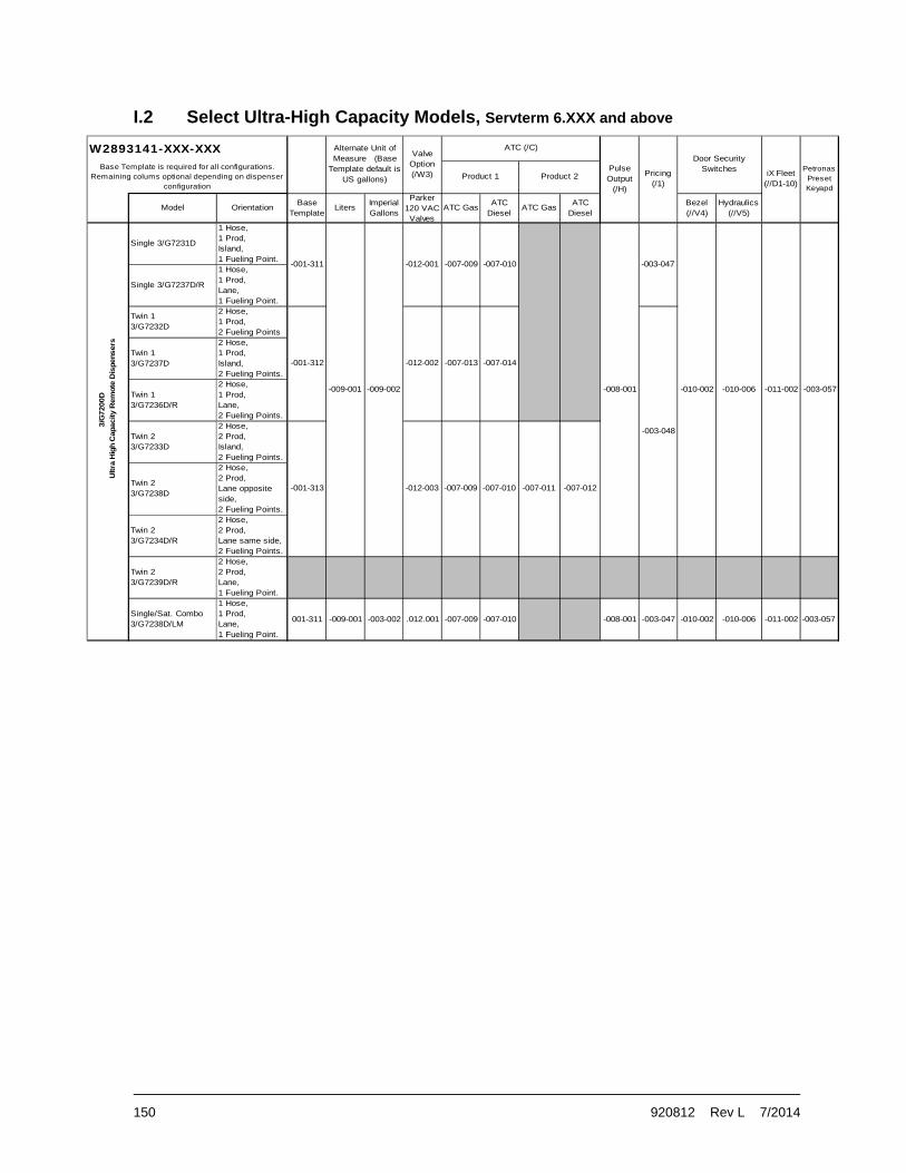
150 920812 Rev L 7/2014
Model OrientationBase
TemplateLiters
Imperial Gallons
Parker120 VACValves
ATC GasATC
DieselATC Gas
ATC Diesel
Bezel (//V4)
Hydraulics (//V5)
Single 3/G7231D
1 Hose,1 Prod,Island,1 Fueling Point.
Single 3/G7237D/R
1 Hose,1 Prod,Lane,1 Fueling Point.
Twin 13/G7232D
2 Hose,1 Prod,2 Fueling Points
Twin 13/G7237D
2 Hose,1 Prod,Island,2 Fueling Points.
Twin 13/G7236D/R
2 Hose,1 Prod,Lane,2 Fueling Points.
Twin 23/G7233D
2 Hose,2 Prod,Island,2 Fueling Points.
Twin 23/G7238D
2 Hose,2 Prod,Lane opposite side,2 Fueling Points.
Twin 23/G7234D/R
2 Hose,2 Prod,Lane same side,2 Fueling Points.
Twin 23/G7239D/R
2 Hose,2 Prod,Lane,1 Fueling Point.
Single/Sat. Combo3/G7238D/LM
1 Hose,1 Prod,Lane,1 Fueling Point.
001-311 -009-001 -003-002 .012.001 -007-009 -007-010 -008-001 -003-047 -010-002 -010-006 -011-002 -003-057
-003-048
-007-009 -007-010 -007-011 -007-012
-007-013 -007-014
-003-047
-011-002
3/G
7200D
Ultra
Hig
h C
apacity R
em
ote
Dis
pensers
-012-001 -007-009 -007-010
-009-001 -009-002
-001-313
-001-311
Product 1 Product 2
ATC (/C)
Pulse Output
(/H)
Pricing (/1)
Door Security Switches iX Fleet
(//D1-10)
-008-001 -010-002 -010-006
Petronas Preset Keyapd
-003-057
-012-002
-012-003
W2893141-XXX-XXX Alternate Unit of Measure (Base
Template default is US gallons)
Valve Option(/W3)
Base Template is required for all configurations. Remaining colums optional depending on dispenser
configuration
-001-312
I.2 Select Ultra-High Capacity Models, Servterm 6.XXX and above

920812 Rev L 7/2014 151
I.3 Select High and Super-High Capacity Models - Gallons, Servterm 5.XXX
Model Gal
lon
s
8876
95-0
15
Gal
lon
s w
ith
Pu
lse
Ou
tpu
t (/
H)
8876
95-0
15
Gal
lon
s w
ith
Pri
cin
g (
/1)
8876
95-0
15
Gal
lon
s w
ith
Pri
cin
g &
Pu
lse
Ou
tpu
t (/
1H)
8876
95-0
153/G7201D/23/G7207D/2R3/G7203D/23/G7203D/283/G7208D/23/G7208D/283/G7242D/23/G7247D/23/G7201P/23/G7207P/2R3/G7202P/23/G7207P/23/G7203P/23/G7203P/283/G7208P/23/G7208P/283/G7221D3/G7227D3/G7227D/R3/G7227D/M3/G7227D/MR3/G7228D/LM3/G7221P/83/G7227P/8R
/059/059
/060/060
/057/057
/058/058
/033 /034 /037 /038/033 /034 /037 /038/043 /044 /047 /048/031 /032 /035 /036/041 /042 /045 /046/031 /032 /035 /036/023 /024 /025 /026/021 /022/023 /024 /025 /026/021 /022/011 /012 /015 /016/011 /012 /015 /016/001 /002 /003 /004/001 /002 /003 /004/011 /012 /015 /016/011 /012 /015 /016/023 /024 /025 /026/021 /022/023 /024 /025 /026/021 /022
/003 /004/001 /002 /003 /004/001 /002

152 920812 Rev L 7/2014
I.4 Select Ultra-High Capacity Models – Gallons, Servterm 5.XXX
Model Ga
llo
ns
887
695-
015
Ga
llon
s w
ith
Pu
lse
Ou
tpu
t (/
H)
887
695-
015
Ga
llon
s w
ith
Pri
cin
g
887
695-
015
Ga
llo
ns
wit
h P
rici
ng
& P
uls
e O
utp
ut
(/1
H
887
695-
015
3/G7231D//W33/G7231D3/G7237D/MR/W33/G7237D/MR3/G7238D/LM/W33/G7238D/LM3/G7232D//W33/G7232D3/G7237D/M/W33/G7237D/M3/G7236D/M/W33/G7236D/M3/G7233D//W33/G7233D3/G7238D/M/W33/G7238D/M3/G7234D/MR/W33/G7234D/MR
/255 /256 /281 /282
/255 /256 /281 /282
/255 /256 /279 /280
/253 /254 /277 /278
/253 /254 /277 /278
/253 /254 /275 /276
/251 /252 /273 /274
/251 /252 /273 /274
/251 /252 /271 /272
/055 /056 /081 /082
/055 /056 /081 /082
/055 /056 /079 /080
/053 /054 /077 /078
/053 /054 /077 /078
/053 /054 /075 /076
/051 /052 /073 /074
/051 /052 /073 /074
/051 /052 /071 /072

920812 Rev L 7/2014 153
I.5 Select High and Super-High Capacity Models – Liters, Servterm 5.XXX
Model Lit
ers
887
705-
015
Lit
ers
wit
h P
uls
e O
utp
ut
(/H
)
887
705-
015
Lit
ers
wit
h P
rici
ng
(/1
)
887
705-
015
Lit
ers
wit
h P
rici
ng
& P
uls
e O
utp
ut
(/1H
)
887
705-
015
Lit
ers
wit
h A
TC
(/C
)
887
705-
015
Lit
ers
wit
h A
TC
& P
uls
e O
utp
ut
(/C
H)
887
705-
015
Lit
ers
wit
h P
rici
ng
& A
TC
(/1
C)
887
705-
015
Lit
ers
wit
h P
rici
ng
& A
TC
& P
uls
e O
utp
ut
(/C
H)
887
705-
015
3/G7201D/23/G7207D/2R3/G7203D/23/G7203D/283/G7208D/23/G7208D/283/G7242D/23/G7247D/23/G7201P/23/G7207P/2R3/G7202P/23/G7207P/23/G7203P/23/G7203P/283/G7208P/23/G7208P/283/G7221D3/G7227D3/G7227D/R3/G7227D/M3/G7227D/MR3/G7228D/LM3/G7221P/83/G7227P/8R
/137/137
/057 /058 /059 /060 /157 /158 /159/134
/135/145/135/147
/125
/125
/103/103/115/115
/125/117/117
/103/103
/125
/160/057 /058 /059 /060 /157 /158 /159 /160
/142/132/144/134
/133/133
/038
/112/122
/122
/132
/124
/124
/038
/102/122
/122/124
/114/114/102/102
/121/123
/112
/141
/111/121
/121
/131
/123
/123
/113/113/101/101
/036/048
/131/143
/004/016 /111
/046
/016
/036
/026
/026
/037
/004/004
/016/016/004
/047/037
/015
/035
/025
/025
/045/035
/034
/003/003
/015/015/003/003/015
/042/032/044/034
/022
/022
/032
/024
/024
/002/002/012/012
/022
/022
/012/012
/031/043/033/033
/031
/023
/023
/041
/011/011/021
/021
/011/011/001/001
/001
/023
/023 /024
/024
/001/021
/021
/002/002
/025 /026 /123 /124
/026/025
/104/101/101/121
/102/104
/126
/126/118/118/104/104/116/116
/126
/126
/138/138
/136/146/136/148

154 920812 Rev L 7/2014
I.6 Select Ultra-High Capacity Models – Liters, Servterm 5.XXX
Model Lit
ers
8877
05-0
15
Lit
ers
wit
h P
uls
e O
utp
ut
(/H
)
8877
05-0
15
Lit
ers
wit
h P
rici
ng
(/1
)
8877
05-0
15
Lit
ers
wit
h P
rici
ng
& P
uls
e O
utp
ut
(/1
H
8877
05-0
15
Lit
ers
wit
h A
TC
(/C
)
8877
05-0
15
Lit
ers
wit
h A
TC
& P
uls
e O
utp
ut
(/C
H)
8877
05-0
15
Lit
ers
wit
h P
rici
ng
& A
TC
(/1
C)
8877
05-0
15
Lit
ers
wit
h P
rici
ng
, AT
C &
Pu
lse
Ou
tpu
8877
05-0
15
3/G7231D//W33/G7231D3/G7237D/MR/W33/G7237D/MR3/G7238D/LM/W33/G7238D/LM3/G7232D//W33/G7232D3/G7237D/M/W33/G7237D/M3/G7236D/M/W33/G7236D/M3/G7233D//W33/G7233D3/G7238D/M/W33/G7238D/M3/G7234D/MR/W33/G7234D/MR
/355 /356 /381 /382/255 /256 /281 /282
/356 /379 /380
/255 /256 /281 /282 /355 /356 /381
/256 /279 /280 /355
/378
/253 /254 /277 /278 /353 /354 /377 /378/153
/354 /375 /376
/253 /254 /277 /278 /353 /354 /377
/254 /275 /276 /353
/352 /373 /374
/251 /252 /273 /274 /351 /352 /373
/252 /273 /274 /351
/351 /352 /371 /372/251 /252 /271 /272
/181
/177
/177
/179
/181
/171
/173
/173
/175
/155
/152
/152
/152
/154
/156
/154
/154
/156
/156
/153
/155
/155
/151
/151
/151
/153
/081
/072
/074
/074
/076
/078
/078
/080
/082
/082
/077
/077
/079
/081
/071
/073
/073
/075
/055
/052
/052
/052
/054
/054
/054
/056
/056
/056
/053
/053
/055
/055
/255
/051
/051
/051
/053
/251
/253
/172
/174
/174
/176
/374
/182
/178
/178
/180
/182/382
“//W3” models use 2-stage 120 VAC valves.

920812 Rev L 7/2014 155
Appendix J
Error Codes
Code Error Description1 Flash program CRC error Corrupted program data detected in POST (Power
On Self Test) 2 Flash template CRC error Corrupted Template Data detected in POST
3 RAM Error RAM test failed. The RAM test runs in POST and before the start of a sale.
5 RAM error log CRC error Corrupted RAM error log detected in POST
6 RAM function programming CRC error Corrupted RAM function data detected in POST
7 RAM unit prices CRC error Corrupted RAM unit price data detected in POST
8 RAM statistics CRC error Corrupted RAM statistics data detected in POST
9 RAM event log CRC error Corrupted RAM event log data detected in POST
10 RAM totals CRC error Corrupted RAM totals data detected in POST
11 RAM totalizers CRC error Corrupted RAM totalizer data detected in POST
12 RAM Electro-mechanic totalizers CRC error
Corrupted RAM EMT data detected in POST
13 Identi-PROM CRC error- Device #0 = Display, Device #1 = CPU
Identi-PROM data is only required for Ovation dual price posting displays and Century/Select displays.
14 RAM Timestamps CRC error Corrupted RAM timestamp data detected in POST
16 Suppress overflow limit reached This error is logged if overrun suppression is enabled (function 19.12 and 19.22) and the limit is exceeded)
17 RAM meter data CRC error Corrupt RAM meter Non-volatile data detected in POST
18 RAM Door Security Data CRC Error Corrupt RAM Door Security Data detected in POST
20 n Consecutive display read back error- Device #s: 0=Sales, 1=Unit price, 2=Preset
Data which is sent to the displays is echoed back to verify connection and display board integrity. The data received from the display does not match the data sent. The number of readback errors allowed is specified in function 17.02
25 Sale cannot start-Zero Unit price Unit price not set
27 Sale cannot start-Unit price changed Unit price has changed too close to the start of a sale. The time is set/disabled through function 23.04
28 Sale cannot start-Need preset entry Sales requires an entry from preset keypad if enabled in function 24.01
30 No communications with POS timeout Communication lost with POS for the amount of time specified in function 23.02
31 POS buffer overflow (DART) Communication error with POS
34 Sale aborted because Stop Button pushed Stop button signal was detected

156 920812 Rev L 7/2014
Code Error Description35 Blend ratio out of tolerance Total sale blend ratio exceeded the limits specified
in functions 7.02-7.04 39 Pulse output lags by more than 1 second Pulse output being sent to the POS was not able to
keep up with the sale flow rate 42 Vapor recovery motor on when it should
be off Signal from the WayneVac system indicating that the motor is turning when there is no fuel flow
43 Vapor recovery motor on when it should be on
Signal from the WayneVac system indicating that the motor is not turning when there is fuel flow
46 Vapor recovery motor turning wrong direction
Feedback signals from the WayneVac system indicate that the motor is turning in the wrong direction
47 Illegal sensor states from vapor recovery system
Feedback signals from the WayneVac system indicate that the sensor signals are corrupted
48 Vapor recovery motor load high Amount of power required to run the WayneVac motor has exceeded expected levels
49 Vapor recovery motor load low Amount of power required to run the WayneVac motor is less than expected
50 Jitter/Reverse limit reached on an In Transaction WIP
The meter has reported that amount of jitter pulses during a sale has exceeded the number of pulses specified in function 17.00
51 Jitter limit reached on an idle WIP The meter has reported that amount of jitter pulses while the meter was idle has exceeded the number of pulses specified in function 17.01
54 Reverse flow limit reached on idle WIP The meter has reported that amount of reverse pulses while the meter was idle has exceeded the number specified in function 16.03
56 Forward flow limit reached on an idle WIP The meter has reported that the amount of forward pulses while the meter was idle has exceeded the number specified in function 19.14/19.24
58 Communication lost to an In Transaction WIP
Meter is not communicating with iGem. A communication timeout occurred while the meter was in use during a transaction
59 Communication lost to an idle WIP Meter is not communicating with iGem. A communication timeout occurred while the meter was idle
62 WIP is outputting jitter during calibration Volume exceeded expected limit during calibration
67 Meter calibration OK bit status changed Meter status changed from un-calibrated to calibrated
68 Meter calibration door status changed Meter calibration door was closed
69 Meter last calibration status changed Meter last calibration indicated as successful
70 Timeout reached for No Flow Start of flow not detected for the amount of time as specified in function 17.03
71 Consecutive No Flow timeouts Consecutive no flow errors have been detected for the number of fillings specified in function 17.04
72 Timeout limit reached for flow lost during sale
Flow was lost for the amount of time specified in function 17.03
73 Consecutive Flow Lost timeouts Consecutive flow lost errors have been detected for the number of fillings specified in function 17.05
74 Sale terminated before preset limit reached
Sale did not reach preset limit set
75 Consecutive unfinished fillings Consecutive sales did not reach the preset limit. Number of sales is specified in function 17.06
76 DEF Low Temperature Event DEF temperature change signal received; 1=Low Temp, 2=Low Temp Cleared

920812 Rev L 7/2014 157
Code Error Description
77 Additive Error Device #s: 0=Config error 1=CAN comm error 2=Tank empty 3=Tank door open 4=Motor failure 5=Injection fell short 6=Flow error
0=Additive config conflict 1=No response from additive 2=Tank reported empty 3=Tank door reported open 4=Additive motor not turning 5=Additive injector not able to keep up w/ flowrate 6=Additive flow not detected
80 Software exception encountered 0=Mail buffer pool exhausted 1=Mail send failed 2=XMalloc failed 3=Print buffer overflow
Internal iGem board error indication
90 Fuel temperature board communication failure
iGem has lost communication with the FTB, Fuel Temperature Board
91 Fuel temperature board temperature probe shorted
Defective or out of range probe detected by the FTB
92 Fuel temperature board temperature probe shorted
Defective or out of range probe detected by the FTB
94 ATC configuration error ATC function data programmed incorrectly
95 Fuel Temp Board Calib error
96 Dispenser security breached Device numbers: 1=Bezel door 2=Hydraulic door
Door sensor switch activity detected while armed
97 Dispenser security armed status change Device numbers: 0=Dispenser unarmed 1=Dispenser armed using One-Shot 2+Dispenser armed using Maint Mode
Date/Time that door security was armed/unarmed
98 DEF errors, Device (D), Side (S) DEF errors
99 Hardware/Software mismatch – Device #s: 0=No proportional hardware, 1=No vapor recovery hardware, 2=Meter does not match F16.04, 3=Ovation II not enough upd’s installed, 4=Ovation II too many upd’s installed
Hardware configuration problem detected. Hardware signal is missing

158 920812 Rev L 7/2014

920812 Rev L 7/2014 159
002-305216-HRN (twin super high cap)001-305216-HRN (All except twin super high cap)
887339-001 887001-001
The Number of Valves Varies According to Single/Twin and Super High Cap Dispensers(See applicable Hydraulics
Section)
Communication Cable to J25 is part
of Conduit Assy. leading to Field
Connection Junction Box
J16
J15
J7
J6
J4
J1J7
J5
J25
J3
J1
J2
J5J4J3J2J6
Intrinsic Safe Barrier
iGEM Computer
JunctionBox
Sol APrim
Nozzle 1A Nozzle 1B
Magnet
SensorSensor
Magnet
Pulser 1WIP 1
PulserChan 1
PulserChan 5
J8 J9 J10 J11 J12
J14
Vapor Barrier
Sol BPrim
Sol ASec
Sol BSec
PulserChan 6
PulserChan 2
Pulser 2WIP 2
One Nozzle for Singles and Two for Twins
The Number of Pulser / WIPs Varies According to Single/Twin and Super High
Capacity Dispensers(See applicable Hydraulics Section)
Appendix K
Internal Wiring & Connections
K.1 Internal Wiring – CPU (Non UHC Models)

160 920812 Rev L 7/2014
Potted AC Harness conduit
To PowerSupply
To PumpRelay
Board (J9)
To PumpRelay
Board (J1)
890925-001
(3/G7239D/R)
8925
10-
003
DataComputer
Main Junction Box
Gra
y
Bro
wn
892509-001
Solenoid
Slow FastFast
Bla
ckR
edY
ello
w
Bla
ckR
ed
Solenoid
Potted IS Wires
TempProbe 2
(ATC ONLY)
TempProbe 1(ATC
ONLY)
J11Pwr/CAN
BUS
J7J1
J4J3J2
IntrinsicSafe
Barrier
Nozzle 1A Nozzle 1B
SensorSensorPulser 1
Vapor Barrier
Pulser 2
(9) (9)
(2)(2)
J5 J6
LEDPulse A&B
Side 1
Pulser 1&2Detect
LEDPulse A&B
Side 1Pulser 1&2
Detect
LEDPulse A&B
Side 2 Nozzles
Side A1Valve 1/3
Side B1 or A2Valve 5/7
890968-001 OR889534-003 (ATC Only)
Slow
Yel
low
892
509-
001
Red
S1
V2
S1V
4
S2
N4
or S
1N3
Red
Red
Red
Whi
te
Whi
te
S2V
6
S2V
8
S1
N4
Side BSide A
892510-001
892508-001
Co
mm
on
Val
ve 1
Val
ve 3
Val
ve 4
Val
ve 2
Val
ve 2
Val
ve 4
Val
ve 3
Val
ve 1
Co
mm
on
Pump Relay Board Pump Relay Board
J3Valves
J4 J5 J8 J9 J10 J11 J12Nozzles WIP
887001-001
PPM
J8J7J5J6 J1J10
J9J4
Side 2 Side 1
WIP
sN
ozzl
es
Pwr890679-001 OR
891090-001
ATC ONLY
891203-001
J25
J1
J2
J14
J13
J6
J7 J16
J15
iGEM Computer
A B
Power ToPOB (J18)
882302-004
890679-002
ISB
+
[NOTE: SEE 890871-001 FOR UHC WITH ASCO VALVES]
K.2 Internal Wiring – CPU (UHC Models with 115 VAC valves)

920812 Rev L 7/2014 161
889534-003 Potted IS with ATC890968-001 Potted IS Non-ATC
To PowerSupply
Potted AC Harness conduit
Solenoid BSolenoid A
Pwr
Valves WIPNozzles
Noz
zles
WIP
s
Side 1Side 2
Nozzles
LEDPulse A&B
Side 2Pulser 1&2
Detect
LEDPulse A&B
Side 1
Pulser 1&2Detect
LEDPulse A&B
Side 1
J6J5J4
J9
J10 J1 J6 J5 J7 J8
Gra
yB
row
n
J13
S2
N4
S1
N4
VA
L-
S1
VX
S1
VX
ISB
+
Red
Red
Red
Whi
te
Whi
te
Whi
te
(2) (2)
(9)(9)
Fast Slow
PPM
Pulser 2
Blu
eV
iole
t
Slow
Vapor Barrier
J14
J12J11J10J9J8
Pulser 1 Sensor SensorNozzle 1BNozzle 1A
Fast
JunctionBox
iGEM Computer
Intrinsic Safe Barrier
J2 J3 J4
J2
J1
J3
J25
J5
J1 J7
J4
J6
J7
J15
J16
To Pump RelayBoard (J2)
To Pump RelayBoard (J1)
Vapor Barrier
Pwr/CANBUS
J11
(ATC ONLY)
TempProbe 1(ATC
ONLY)
TempProbe 2
(ATC ONLY)
Potted IS Wires
Power toPOB (J18)
881877-002
890679-001887001-001
891090-001
K.3 Internal Wiring – CPU (UHC Models with 24 VDC valves)

162 920812 Rev L 7/2014
iGEM Computer
J16
J15
J1 J2
J5
J6 Display B1(J-Box Side)
iGEM Computer
Display A1(J-Box Side)
J6
J5
J2J1
Display B1J6
J5
J2J1 J1 J2
J5
J6
Display A1
Side BComponentsfor Twins Only
Side BComponentsfor Twins Only
Display A1
J1 J2
J5
J6
J1 J2
J5
J6
J15
J16
Display B1(J-Box Side)
Lane-Oriented
Nozzle
A1
B1B1
Display
Display
NozzleA1
Main J-Box Main J-Box Main J-Box
2 Hose Dispenser1 Hose Dispenser 2 Hose, Same Side Dispenser
Display
A1Nozzle
A1
Nozzle
A1Display
A1A2
Nozzle
Nozzle
A11 Hose Dispenser
Main J-Box
A1
A1
Display
Display
Nozzle
Nozzle
B1
A12 Hose Dispenser
Main J-Box
A1 B1
A1 B1
Display Display
DisplayDisplay
TotalizerSide A
J6
J7
TotalizerSide B (twins)
TotalizerSide A
J7
J6
887596-001
TotalizerSide B (twins)
Island-Oriented
887596-001
886486-005 886486-001 886486-005
886486-001
001-305740-
001-305740-
886486-001 886486-001
887596-001887596-001
001-305740-001-305740-
K.4 Internal Wiring – Displays

920812 Rev L 7/2014 163
LineFilter
Terminal Block Assy
DC 24VWhiteBlack
To iGEM J1
Blu
eV
iole
t
To iGEM J2
Blu
e
White
BlueB
lue
Whi
te
PCB Assy, Pump Relay BoardV
iole
t
Ye
llow
Red
Gre
enB
lack
Wh
ite
GreenBlackWhite
Vapor Barrier
Junction Box
WhiteBlue
Lamp
LampBallast
PowerSupply
AC
42 PE 3P NPE 1
Ballast
Remote Wiring Sample
K.5 Internal Wiring – Power for Remote Dispensers

164 920812 Rev L 7/2014
Vio
let
Vio
let
Blu
eB
lue
Vio
let
Vio
let
BlackWhiteFrom Heater/Fan
Cable 892264-001
From Heater/FanCable 892264-001
WhiteBlack
Suction Wiring Sample1 Motor
Ye
llow
Red
Gre
enB
lack
Whi
te
BlackWhite
Vapor Barrier
Junction Box
WhiteBlue
Lamp
LampBallast
PowerSupply
AC
42 PE 3P NPE 1
13
7 49 6
BA 1
MOTOR
Suction Wiring Sample2 Motors
Bla
ckB
lack
Ballast
BlueWhite
Ballast
Bla
ckB
lack
To iGEM J2
MOTOR
1AB
6947
31
1PE NP 3PE2 4
DC 24V
AC
BallastLamp
Lamp
Junction Box
Vapor Barrier
WhiteBlackGreen
Whi
teB
lack
Gre
en
Red
Ye
llow
13
7 49 6
BA 1
MOTOR
Red
Red
BlackRed
Red
Black
Black
Bla
ckB
lack
Bla
ckB
lack
Bla
ckB
lack
DC 24V
Bla
ckB
lack
WhiteBlack
To iGEM J1
Green
To iGEM J1BlackWhite
WhiteBlue
BlueWhite
Relay
LineFilter
Relay Relay
LineFilter
Terminal Block Assy
Terminal Block Assy
PowerSupply
To iGEM J2
K.6 Internal Wiring – Power for Suction Pumps

920812 Rev L 7/2014 165
Auth BAuth A
Res
et
Pul
se
Pulser B1Y-Pulser B1Y+
Pulser A1Y-Pulser B1X+
Pulser A1Y+Pin 1
POB - J2
AC Hot In
Reset A
Reset B
AC Auth B
Neut Ref
AC Auth A
POB - J1
Pin
1
Pin 1
Pulser A1X-
POB - J5
Pulser B1X- Pulser A1X+
Pin
9
002-306565- Twin001-306565- Single
890154-001 890154-001
888814-002 888814-002
To Terminal Block Pos. 1(Blue 18AWG, AC Hot)
P
N
To Terminal Block Pos. 2(White 18AWG, AC Neutral)
Vapor Barrier
For Units with 2 Displays per Side, Connect to Display
Closest to POB
Junction Box
For Units with 2 Displays per Side, Connect to Display
Closest to POB
Pulse Output Board & Screws(mount to back side of iGEM bracket)
Display B1
J1 J2
J5
J6
From Power Supply(see Elec Module)
J17J18 J11J10J9J8
Pulser 2Pulser 1CallResetAuthJ6J2J1 J4 J5
J3B
J3A
J6
J5
J2J1
Display A1
J16
J15
J7
J6
J4 J5
J25
J3
J1
J2
iGEM Computer
J8 J9 J10 J11 J12
J14
K.7 Internal Wiring – Pulse Output

166 920812 Rev L 7/2014
SIDE B (UHC-115 VAC Valve)RELAY-J2
Pin 1
White S2V7 Mas Fast
White S2V5 Mas Slow
White S2V6 Sat Slow
White S2V8 Sat Fast
White CommonWhite Common
White S1V4 Sat Fast
White S1V2 Sat Slow
White S1V1 Mas Slow
White S1V3 Mas Fast
SIDE A (UHC-115 VAC Valve)RELAY-J2
Pin 1
24
VD
C
Pin 1
Mo
tor
1
Mo
tor
2M
otor
424
VD
CM
oto
r 3
CPU-J2
24 V
DC
24
VD
C
Pin 5
Pin 9
Gn
d
Gn
d
Gn
d
Gn
d
Gn
d
Gn
d
CPU-J4
Noz
5 (
S2
N1)
Gn
dN
oz 6
(S
2N
2)
Noz
7 (
S2
N3)
Noz
8 (
S2
N4)
Noz
4 (
S1
N4)
Noz
3 (
S1
N3)
Noz
2 (
S1
N2)
Gn
dN
oz 1
(S
1N
1)
Pin 11
Val
ve 1
0 (-
V)
Va
lve
10
(+V
)
Val
ve 8
(-V
)V
alve
8 (
+V
)
Val
ve 7
(-V
)V
alve
7 (
+V
)
Val
ve 6
(-V
)V
alve
6 (
+V
)
Val
ve 5
(+
V)
Val
ve 9
(-V
)V
alve
9 (
+V
)
Val
ve 4
(-V
)V
alve
4 (
+V
)
Val
ve 3
(-V
)V
alve
3 (
+V
)
Val
ve 2
(-V
)V
alve
2 (
+V
)
Val
ve 1
(+
V)
Val
ve 5
(-V
)V
alve
1 (
-V)
PIN 1PIN 1
Pin 1Pin 1
Blue (Subm Y)
Violet (Subm X)
RELAY-J2
ISB+
CPU-J13
CPU-J3
K.8 Internal Wiring – Connectors

920812 Rev L 7/2014 167
WU003726-0001
PW
R
891
410-
001
J5
WU004075-0002
J6
J1
PP
M
887336-004
887338-004
AC
Dis
t/R
ela
y
Hea
ter
Ass
y
890766-001
887
223
-001
J4
J7
iGE
M
WU001565-0001
J1 P
WR
891
039
-001
WU
004
076-
0001
Doo
r S
ide
#2
Dis
pens
er E
lect
roni
cs P
latfo
rm
NLF
LH
002
-301
823-
Gnd
Str
ap
002
-301
823-
Gnd
Str
ap
WHT
BLK
BLK
The
rmos
tat
850
350-
002
888
798-
002
887621-001
Ann
unci
ator
TR
SM
Ke
ypad
J9
890
565-
001
CA
N
Le
ft S
oft
Key
J5
Pas
sive
A
J21
JP1
WU
000
472-
0001
J8
J11J3
RF
ID
P1
Rig
ht
So
ft K
ey
J13
PW
R
892
141-
001
891
256-
911
TR
SM
J14
J5
WU
000
948
J2
889960-002
P2
P2
J13
GROUND
J24
J4 J1
Eth
ern
et
890
766-
001
001-301823- GROUND STRAP
887
749-
001
J13
CA
N
WU
000
473-
0001
Ant
enn
a
J37
WU
005
377-
0001
J15
WU
010
635-
0002
WU
009
712-
0001
Sca
n
J10
PR
OX
WU004075-0002
PO
B
WU001565-0001
Sof
tK
eys
SD
Ca
rd
Mag
Re
ade
r
Wie
gan
dW
P00
029
2-0
001
Inda
laW
U0
1063
5-00
01
Re
d B
oard
WU
005
588-
0001
Ca
rdR
ea
der
WU
004
539-
0001 QV
GA
Dis
play
RF
ID C
ont
rolle
rW
U0
0421
1-00
01
J4
J14
J13
850
350-
002
Left
So
ft K
eyW
U00
047
2-00
01R
igh
t S
oft K
eyW
U0
0047
3-00
01 J13
RF
ID C
ont
rolle
rW
U0
0421
1-00
01
J9J5 A
nte
nna
890
565-
001
892
141-
001
WU
004
539-
0001
WU
005
377-
0001
890
766-
001
QV
GA
Dis
play
JP1
WU
000
948
888
798-
002
P1
P2
J3 J1J2J5J13
J4J21
Sof
tK
eys
SD
Ca
rd
RF
ID
Ann
unci
ator
CA
N
CA
N
Ca
rdR
ea
der
PW
R
J11
J24
Pas
sive
A
Red
Boa
rdW
U0
0558
8-00
01
Sca
n
Eth
ern
et
TR
SM
J8
J37
J15
WU
004
076-
0001
Inda
laW
U0
1063
5-00
01
WU
010
635-
0002
J4
Wie
gan
dW
P00
029
2-0
001
J10
WU
009
712-
0001
891
256-
911
887
749-
001
Mag
Re
ade
r
P2
Doo
r S
ide
#1
GROUND 001-301823- GROUND STRAP
889960-002TR
SM
Ke
ypad
887621-001
PR
OX
J13
CA
NJ2
1B
uzz
er
DC
PW
RD
ist
24
VD
C S
up
ply
iX F
leet
Ele
ctro
nics
Pla
tform
Eth
ern
etS
witc
h
K.9 Internal Wiring – iX Fleet

168 920812 Rev L 7/2014

920812 Rev L 7/2014 169
APPENDIX L
Warranty Registration
L.1 Warranty Registration Instructions
The equipment used at this site must be registered prior to contacting Wayne for warranty service. Sites can be pre-registered prior to installation by a Wayne Authorized Service Organization (ASO) via the on-line registration system OR through completing the Section 1 portion of the form, at the end of this manual, and sending it to Wayne (for non-ASOs). Pre-registration of a site helps to expedite warranty service in case it is needed. Please allow 2-3 days after receipt of the information for pre-registration. Final registration, which requires all of the information pertaining to the site including Start-Up date and equipment serial numbers, must be completed within 7 days of the completion of the Start-Up using the same aforementioned methods.
The installed date, which identifies the start of the equipment warranty, will be entered as either:
A. The actual date of install provided by the Installing Contractor.
– OR –
B. 30 days from the date of the Pre-Registration.
Regardless of the method used to determine the start date, all Wayne standard warranty terms and conditions still apply. Fleet equipment is are entitled to one year of full warranty coverage from the installed date, not to exceed 18 months from the date of shipment from Wayne.
NOTE: Any replacement parts or service must be performed by a Wayne Authorized Service Organization (ASO). If you are not an ASO, you must call 1-800-926-3737 to get service.
L.2 Warranty Registration Definitions
End User Company Name: Name of the end user (Company) where the equipment is installed (e.g. “City of Anytown”, “Big Food Distributing”, etc.
Equipment Location: Facility name, such as “Anytown Maintenance Facility.”
Address, City, State, Zip Code: Address of equipment location.
Phone: Telephone number at the site.
Start-up Date: Date equipment was commissioned.
Model Number: Model number of equipment from identification tag on equipment.
Serial Number: Serial number of equipment from serial number tag on equipment.

Please mail to:
Wayne Fueling Systems Attn: Warranty 3814 Jarrett Way Austin, TX 78728
WARRANTY REGISTRATION The equipment used at this site must be registered prior to contacting Wayne for warranty service. Sites can be pre-registered prior to installation by a Wayne Authorized Service Organization (ASO) via the on-line registration system OR through completing this form (information in Section 1) and sending it to Wayne (for non-ASOs). Pre-registration of a site helps to expedite warranty service in case it is needed. Please allow 2-3 days after receipt of the information for pre-registration. Final registration, which requires all of the information pertaining to the site including Start-Up date and equipment serial numbers, must be completed within 7 days of the completion of the Start-Up using the same aforementioned methods. If submitting via this paper form, you may Fax to 512-388-8595 OR e-mail to [email protected] OR mail to the address below.
Section 1 End User Company Name
Equipment Location (Site Name)
Address
City, State, Zip Code
Phone (______) ______________________________________
Section 2 Start-Up Date _________________________________________
Model Number Serial Number Model Number Serial Number
Comments
Form No. 917653-003 Rev B
Notes 1. Any replacement parts and service must be performed by a Wayne Authorized Service Organization (ASO). If you are not an ASO, you must call 1-800-926-3737 to get service. Any
parts and service, performed by an ASO, associated with the start-up should be reported on Service Report Form No. 917652 and attached to this report.
2. Use additional forms as necessary to list all equipment.
3. All information must be supplied/ completed.

© 2014, Wayne Fueling Systems 920812 Rev L 7/2014
INSTALLATION & OPERATION MANUAL
Select™ 3/G7200 Fleet Dispensers © 2014, Wayne Fueling Systems. All rights reserved. Printed in the United States of America. This manual and any software described herein are furnished under the terms of sale or other applicable contract including any license, and may be used or copied only in accordance with those terms. No part of this publication may be electronically or mechanically reproduced, stored in a retrieval system, or transmitted, in any form or by any means, except as permitted by such terms. Translation of this material to another language without express written permission from Wayne Fueling Systems is prohibited. This publication is intended for informational purposes only and this material is subject to change without notice. Wayne Fueling Systems has not made, and does not make, any representations or warranties of any kind, expressed or implied, with respect to any information in the publication, including warranty as to the accuracy, correctness, or completeness of any information. Wayne Fueling Systems shall not be responsible or liable for any damages or losses that occur as a result of the receipt and/or use of the information contained herein. © 2014. Wayne and the Wayne logo are trademarks of registered trademarks of Wayne Fueling Systems in the United States and other countries. Other names are for informational purposes and may be trademarks of their respective owners.
Wayne is located at 3814 Jarrett Way, Austin TX 78728. Wayne’s general telephone number is (512) 388-8311.

© 2014, Wayne Fueling Systems 920812 Rev L 7/2014
NOTE: “This equipment has been tested and found to comply with the limits for a Class A digital device, pursuant to Part 15 of the FCC Rules. These limits are designed to provide reasonable protection against harmful interference when the equipment is operated in a commercial environment. This equipment generates, uses, and can radiate radio frequency energy and, if not installed and used in accordance with the instruction manual, may cause harmful interference to radio communications. Operation of this equipment in a residential area is likely to cause harmful interference in which case the user will be required to correct the interference at his own expense.”
Headquarters Wayne Sweden Wayne China Wayne Brazil Wayne Fueling Dresser Wayne AB Dresser Wayne Dresser Industria e Systems LLC Hanögatan 10, Fuel Equipment Comercio Ltda. 3814 Jarrett Way Box 50559 (Shanghai) Co., Ltd Estrada do Timbo Austin, TX 78728 SE-202 15 Malmö 1221 Dong Lu Road 126-Bonsucesso USA Sweden Pudong, Shanghai Rio de Janiero, Brasil China