installation, operation & maintenance … · instructions for cleveland mixer maintenance rxt...
TRANSCRIPT

INSTRUCTIONS FORCLEVELAND MIXER
MAINTENANCE
RXT & APD AGITATORS
RXT O&M 06/25/2015 JMN
INSTALLATION,OPERATION &
Models: RXT, RXTO, RXTS,RXTM, RXT - 2MModels: APD, APDO, APDS,APDM, APD-2M, SDM, SDS
PAGE INDEX
PAGE TOPIC1 RECEIVING/UNPACKING2 INSTALLATION PREP, PRE INSTALLATION CHECK LIST3 FASTENERS, BOLT TORQUE VALUE CHART4 REDUCER LUBRICATION DETAILS5 PLUS, COMMISSIONING, LONG TERM STORAGE6 SDM FILL QUANTITY7 APD FILL QUANTITY8 RXT FILL QUANTITY9 LUBRICATION CHART10 INSTALLATION NOTES-11-11b FIXING ELEMENT INSTALLATION12 - 13 INSTALLATION NOTES14 EXPANSION CHAMBER15 AUTO LUBRICATOR16 STEADY BEARING TRIPOD ASSEMBLY17 PACKING GLAND/STUFFING BOX SEALS18-19 IMPELLERS AND COUPLINGS20 SIDE ENTRY MIXERS21 SIDE ENTRY MIXER SHUT-OFF PLUG22 TROUBLE SHOOTING
RXT O&M 06/25/2015 JMN
PAGE 1
RXT & APD AGITATOR MANUAL_09-17-15_JN
document the issue.
damage. Once you've contacted the carrier, please contact Cleveland Mixer so we can
delivered with visible damage, please contact the carrier to report the missing pieces or
correct number of skids, crates and cartons. If any of the shipment was not delivered or
Make sure to check the packing slip for your shipment to make sure you've received the
assembly.
discard any packing crates or materials until you've accounted for all the parts of your mixer
mixer accessories may be packed in boxes inside of crates or bolted down to skids. Do not
such as impeller blades, hubs, couplings, steady bearings, seals, keys, hardware and other
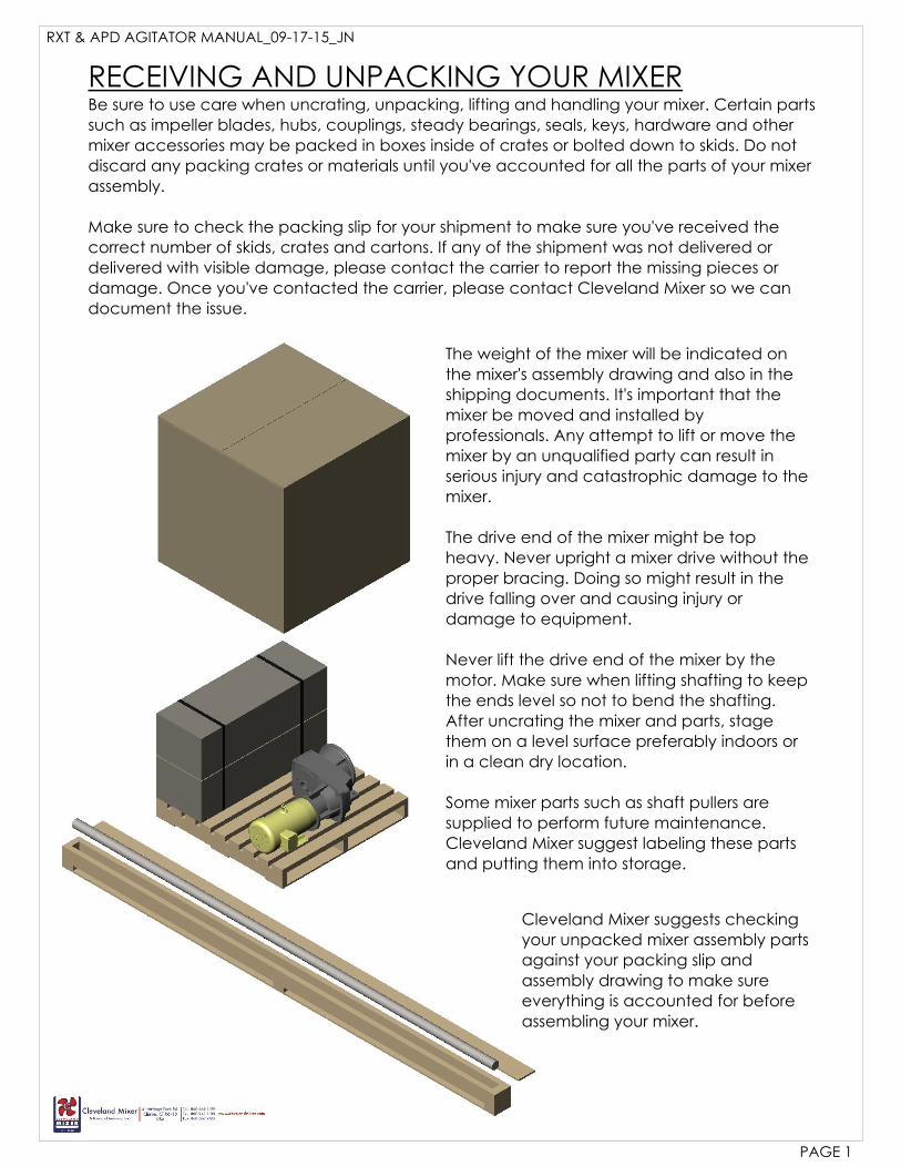
Be sure to use care when uncrating, unpacking, lifting and handling your mixer. Certain parts
RECEIVING AND UNPACKING YOUR MIXER
them on a level surface preferably indoors or
in a clean dry location.
Some mixer parts such as shaft pullers are
supplied to perform future maintenance.
Cleveland Mixer suggest labeling these parts
and putting them into storage.
The weight of the mixer will be indicated on
the mixer's assembly drawing and also in the
shipping documents. It's important that the
mixer be moved and installed by
professionals. Any attempt to lift or move the
mixer by an unqualified party can result in
serious injury and catastrophic damage to the
mixer.
The drive end of the mixer might be top
heavy. Never upright a mixer drive without the
proper bracing. Doing so might result in the
drive falling over and causing injury or
damage to equipment.
Never lift the drive end of the mixer by the
motor. Make sure when lifting shafting to keep
the ends level so not to bend the shafting.
After uncrating the mixer and parts, stage
Cleveland Mixer suggests checking
your unpacked mixer assembly parts
against your packing slip and
assembly drawing to make sure
everything is accounted for before
assembling your mixer.
INSTALLATION SITEMixer drives must be properly installed if they are to produce the rated torque. Improper
installation may lead to oil leaks, reduced life or even catastrophic failure. Cleveland Mixers
are intended to be installed under the following conditions:
Unimpeded airflow to and around the mixer.•
Accessibility to oil drain, motor, seal and breather plugs.•
Mounting surfaces must be level, torsional rigid and dampened against vibration.•
Unless special measures are taken, the immediate vicinity around the mixer drive should•
not be exposed to any aggressive or corrosive substances or gases.
If the mixer has a steady bearing, the shaft and tripod must be properly aligned.•
All bolt connection surfaces must be clean and free from contamination or corrosion.•
Tank walls must be designed to withstand forces created by the mixer.•
Sufficient headroom over the mixer for installation and to be able to perform annual•
maintenance on the mixer.
Designed input voltage or air pressure to run motor. Access to flush materials for seals•
when required.
The responsibility for the design and construction of the support foundation and tank is with
end user. The foundation must be adequate to withstand normal operating loads and possible
overloads while maintaining alignment to attached system components under such loads.
An engineered structural steel foundation should be designed to provide adequate rigidity
and prevent loads from distorting the housing or cause misalignment of internal gears and
shafts.
When flange-mounting the mixer, the bulk head plate must be engineered to minimize
buckling distortions and support the cantilevered weight of the mixer.
If a concrete foundation is used, allow the concrete to set firmly before bolting down the
mixer. Grout structural steel mounting pads and bolts of sufficient size into the concrete to
adequately distribute the load stress onto the concrete foundation.
The mixer must be mounted in the designed position in order to stay properly lubricated.
Consult Cleveland Mixer before making any changes to the mixer or mounting position.
PRE INSTALLATION CHECKMixers are unpacked and all parts are accounted for•
The installation site meets requirements listed above•
A professional is onsite with the correct equipment to safely and securely lift the mixer•
and it's components into position
A professional electrician is onsite to wire the motor/drive•
You have all the necessary tools to install the mixer including a torque wrench (reducer•
hardware will be metric)
You've read through the O&M manual for the mixer, the manual for the motor and•
manuals for mechanical seal or speed drive (if applicable).
The tank is empty, clean and you have access to work inside to install impellers.•
(if your mixer was supplied with a steady bearing assembly) Your steady bearing tripod•
has been laser aligned with the mixer shaft and welded in it's designated location.
RXT & APD AGITATOR MANUAL_09-17-15_JN
PAGE 2
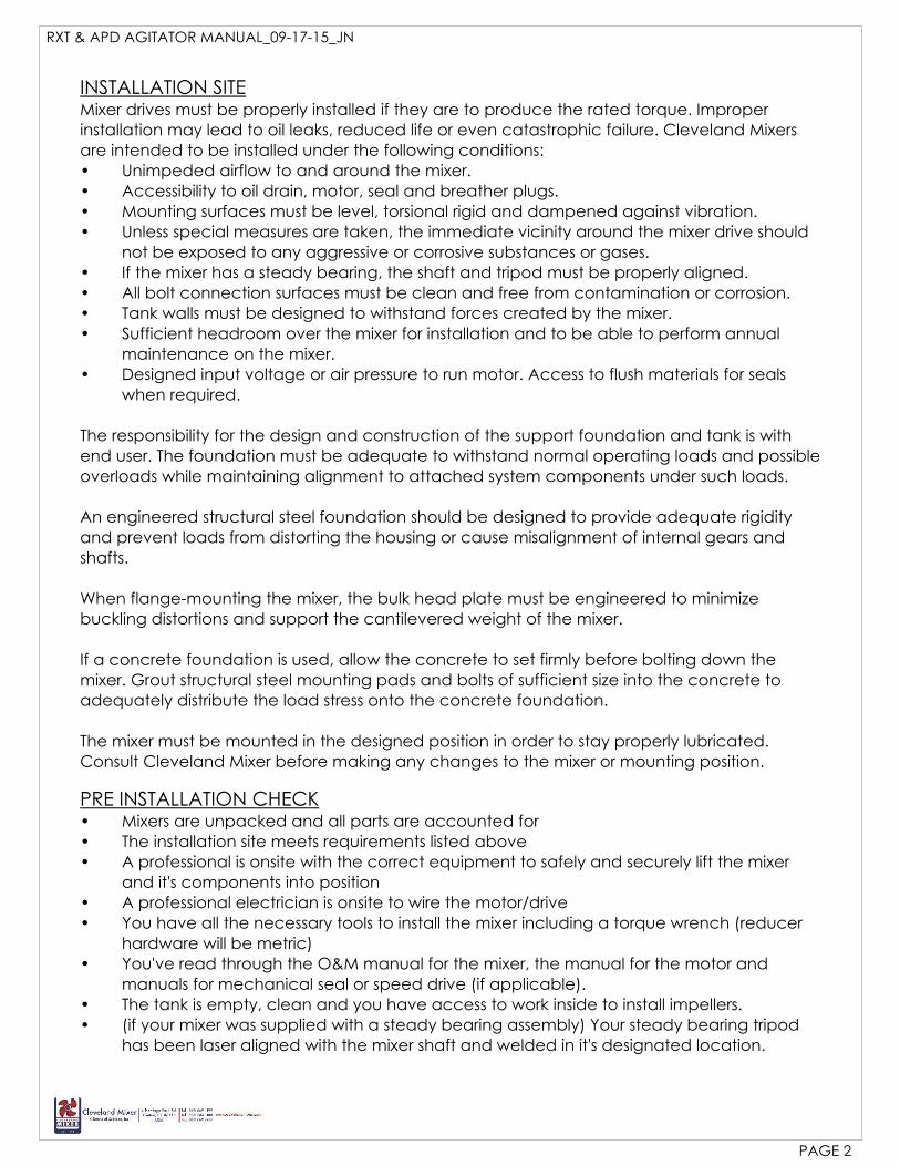
USAStandard GRADE 5 GRADE 8 316 STAINLESS STEEL
THREADSIZE FT LB DRY FT LB
LUBED FT LB DRY FT LBLUBED FT LB DRY FT LB
LUBED
1/4-20 8 6.3 12 9 6 5
5/16-18 17 13 24 18 11 10
3/8-16 30 23 45 35 20 17
7/16-14 50 35 70 50 33 28
1/2-13 75 55 110 80 45 38
9/16-12 110 80 150 110 59 50
5/8-11 150 110 210 160 96 82
3/4-10 260 200 380 280 131 111
7/8-9 430 320 600 450 202 172
1-8 640 480 910 680 299 254
FASTENERS
Tighten all fasteners to the values shown unless specifically instructed to•do otherwise.Lubricate all fasteners at assembly with grease, oil or anti-seize material•If fasteners cannot be lubricated, use dry torque spec provided on chart.•Loose hardware can cause catastrophic damage. It is very important to•check all fasteners at scheduled maintenance intervals.If your process is corrosive or sanitary check the wetted hardware to•make sure it is the correct grade before assembly.Always use washers and lock washers if they were provided.•
Calculated tightening torques are based on conventional 60°F, clean and dry or lubricated
(as indicated above) thread. Standard fasteners will be supplied with a split lock washer.
Cleveland Mixer recommends a minimum of grade 5 (ASTM A449) for all hardware to 1-8 and
grade SAE 8 for larger sizes.
RXT & APD AGITATOR MANUAL_09-17-15_JN
PAGE 3
Oil expansion chamber
connection & oil fill port
(under side)oil drain plug
Cap plate assembly
Oil expansion chamber vent
(rubber plug must be removed for vent to work)
Lower bearing grease port
(motor sizes 250 and up)
Auto lubricator for motor adapter
(motor sizes 250 and up)
Auto lubricator for motor adapter
Oil fill port
(under side)oil drain plug
(under side)oil drain plug
Vertical shaft orientation
Vertical shaft orientation
Horizontal shaft orientation
connection
Oil fill port
Oil fill port Cap plate assembly
Lower bearing grease port
Foot mount
Lower bearing grease port
Cap plate assembly
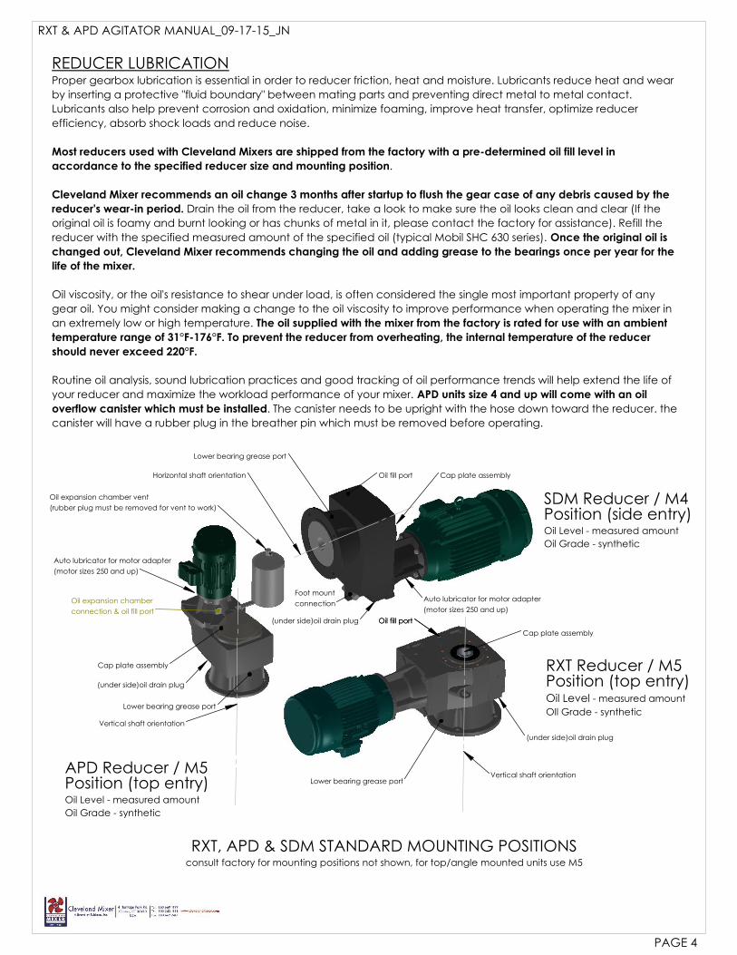
consult factory for mounting positions not shown, for top/angle mounted units use M5
RXT, APD & SDM STANDARD MOUNTING POSITIONS
Position (top entry)APD Reducer / M5
RXT Reducer / M5
OIl Grade - synthetic
- measured amountOil Level
Position (top entry)
Oil Grade - synthetic
Oil Level - measured amount
Position (side entry)SDM Reducer / M4
Oil Grade - synthetic
Oil Level - measured amount
REDUCER LUBRICATIONProper gearbox lubrication is essential in order to reducer friction, heat and moisture. Lubricants reduce heat and wear
by inserting a protective "fluid boundary" between mating parts and preventing direct metal to metal contact.
Lubricants also help prevent corrosion and oxidation, minimize foaming, improve heat transfer, optimize reducer
efficiency, absorb shock loads and reduce noise.
Most reducers used with Cleveland Mixers are shipped from the factory with a pre-determined oil fill level in
accordance to the specified reducer size and mounting position.
Cleveland Mixer recommends an oil change 3 months after startup to flush the gear case of any debris caused by the
reducer's wear-in period. Drain the oil from the reducer, take a look to make sure the oil looks clean and clear (If the
original oil is foamy and burnt looking or has chunks of metal in it, please contact the factory for assistance). Refill the
reducer with the specified measured amount of the specified oil (typical Mobil SHC 630 series). Once the original oil is
changed out, Cleveland Mixer recommends changing the oil and adding grease to the bearings once per year for the
life of the mixer.
Oil viscosity, or the oil's resistance to shear under load, is often considered the single most important property of any
gear oil. You might consider making a change to the oil viscosity to improve performance when operating the mixer in
an extremely low or high temperature. The oil supplied with the mixer from the factory is rated for use with an ambient
temperature range of 31°F-176°F. To prevent the reducer from overheating, the internal temperature of the reducer
should never exceed 220°F.
Routine oil analysis, sound lubrication practices and good tracking of oil performance trends will help extend the life of
your reducer and maximize the workload performance of your mixer. APD units size 4 and up will come with an oil
overflow canister which must be installed. The canister needs to be upright with the hose down toward the reducer. the
canister will have a rubber plug in the breather pin which must be removed before operating.
PAGE 4
RXT & APD AGITATOR MANUAL_09-17-15_JN
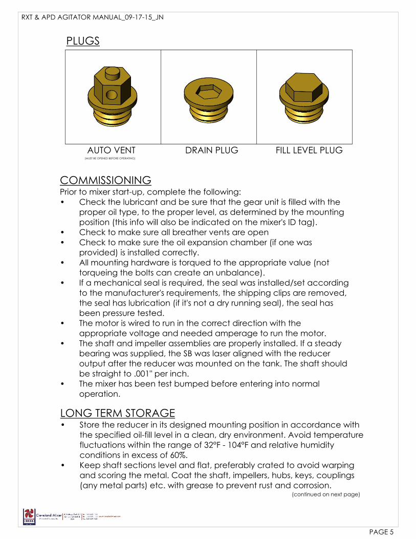
PLUGS
AUTO VENT DRAIN PLUG FILL LEVEL PLUG(MUST BE OPENED BEFORE OPERATING)
COMMISSIONINGPrior to mixer start-up, complete the following:
Check the lubricant and be sure that the gear unit is filled with the•proper oil type, to the proper level, as determined by the mountingposition (this info will also be indicated on the mixer's ID tag).Check to make sure all breather vents are open•Check to make sure the oil expansion chamber (if one was•provided) is installed correctly.All mounting hardware is torqued to the appropriate value (not•torqueing the bolts can create an unbalance).If a mechanical seal is required, the seal was installed/set according•to the manufacturer's requirements, the shipping clips are removed,the seal has lubrication (if it's not a dry running seal), the seal hasbeen pressure tested.The motor is wired to run in the correct direction with the•appropriate voltage and needed amperage to run the motor.The shaft and impeller assemblies are properly installed. If a steady•bearing was supplied, the SB was laser aligned with the reduceroutput after the reducer was mounted on the tank. The shaft shouldbe straight to .001" per inch.The mixer has been test bumped before entering into normal•operation.
LONG TERM STORAGEStore the reducer in its designed mounting position in accordance with•the specified oil-fill level in a clean, dry environment. Avoid temperaturefluctuations within the range of 32°F - 104°F and relative humidityconditions in excess of 60%.Keep shaft sections level and flat, preferably crated to avoid warping•and scoring the metal. Coat the shaft, impellers, hubs, keys, couplings(any metal parts) etc. with grease to prevent rust and corrosion.
(continued on next page)
PAGE 5
RXT & APD AGITATOR MANUAL_09-17-15_JN

LONG TERM STORAGE(continued from previous page)
Store the mixer in an area away from shock and vibration.•Once every 2-3 months, rotate the output shaft 10-20 revolutions to keep•the gears and bearings drying out and seizing up.Avoid direct exposure to the sun or UV light and aggressive or corrosive•materials in the environment.Drain the oil and refill the reducer with fresh oil before putting the mixer•back into operation.Your mixers motor will come supplied with it's own set of operating and•maintenance instructions. Please follow those instructions for long termstorage of the motor.If your mixer requires a mechanical seal, drive unit or any other•components supplied with a separate manufacturers operation andmaintenance manual, please follow those instructions for long termstorage of those components.
OIL FILL QUANTITY, MODEL SDM - SIDE ENTRY
MIXER MODEL UNIT OF MEASURE FILL QUANTITY
SDM-2QUARTS 2.01
LITERS 1.90
SDM-3QUARTS 3.44
LITERS 3.25
SDM-4QUARTS 5.02
LITERS 4.75
SDM-5QUARTS 7.93.
LITERS 7.50
SDM-6QUARTS 12.68
LITERS 12.00
SDM-7QUARTS 21.24
LITERS 20.00
SDM-8QUARTS 31.71
LITERS 30.00
NOTE: SDM units do not require the use of an oil expansion chamber.The breather plug must be positioned above the oil fill line. Clevelandrecommends changing the oil once per year.
PAGE 6
RXT & APD AGITATOR MANUAL_09-17-15_JN
PAGE 7
RXT & APD AGITATOR MANUAL_09-17-15_JN
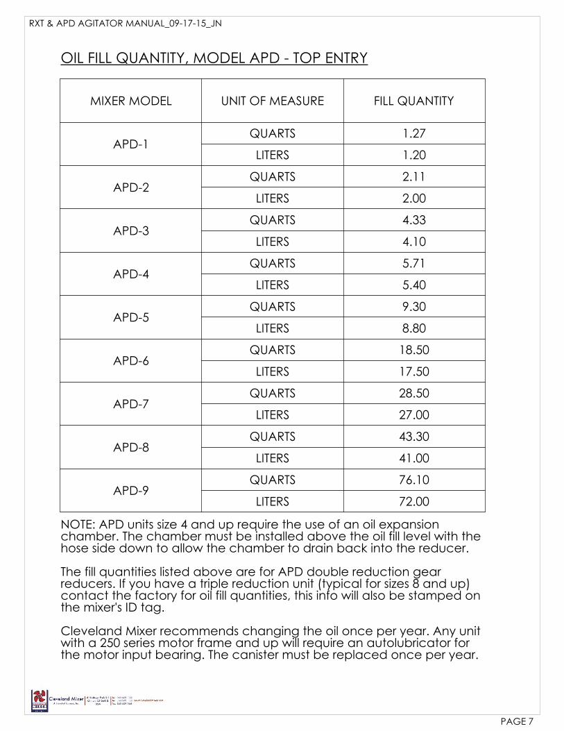
MIXER MODEL UNIT OF MEASURE FILL QUANTITY
APD-1QUARTS 1.27
LITERS 1.20
APD-2QUARTS 2.11
LITERS 2.00
APD-3QUARTS 4.33
LITERS 4.10
APD-4QUARTS 5.71
LITERS 5.40
APD-5QUARTS 9.30
LITERS 8.80
APD-6QUARTS 18.50
LITERS 17.50
APD-7QUARTS 28.50
LITERS 27.00
APD-8QUARTS 43.30
LITERS 41.00
APD-9QUARTS 76.10
LITERS 72.00
OIL FILL QUANTITY, MODEL APD - TOP ENTRY
NOTE: APD units size 4 and up require the use of an oil expansionchamber. The chamber must be installed above the oil fill level with thehose side down to allow the chamber to drain back into the reducer.
The fill quantities listed above are for APD double reduction gearreducers. If you have a triple reduction unit (typical for sizes 8 and up)contact the factory for oil fill quantities, this info will also be stamped onthe mixer's ID tag.
Cleveland Mixer recommends changing the oil once per year. Any unitwith a 250 series motor frame and up will require an autolubricator forthe motor input bearing. The canister must be replaced once per year.

MIXER MODEL UNIT OF MEASURE FILL QUANTITY
RXT-1QUARTS 1.27
LITERS 1.20
RXT-2QUARTS 2.43
LITERS 2.30
RXT-3QUARTS 3.49
LITERS 3.30
RXT-4QUARTS 6.87
LITERS 6.50
RXT-5QUARTS 12.2
LITERS 11.5
RXT-6QUARTS 20.1
LITERS 19.0
RXT-7QUARTS 20.1
LITERS 19.0
RXT-8QUARTS 40.2
LITERS 38.0
RXT-9QUARTS 87.0
LITERS 82.0
OIL FILL QUANTITY, MODEL RXT - TOP ENTRY
NOTE: RXT units do not require the use of an oil expansion chamber.These are top entry angled, helical bevel units. The other mixers in thisseries are vertical helical units.
The fill quantities listed above are for RXT double reduction gearreducers. If you have a triple reduction unit (typical for sizes 8 and up)contact the factory for oil fill quantities, this info will also be stamped onthe mixer's ID tag.
Cleveland Mixer recommends changing the oil once per year.
PAGE 8
RXT & APD AGITATOR MANUAL_09-17-15_JN
RXT & APD AGITATOR MANUAL_09-17-15_JN
PAGE 9
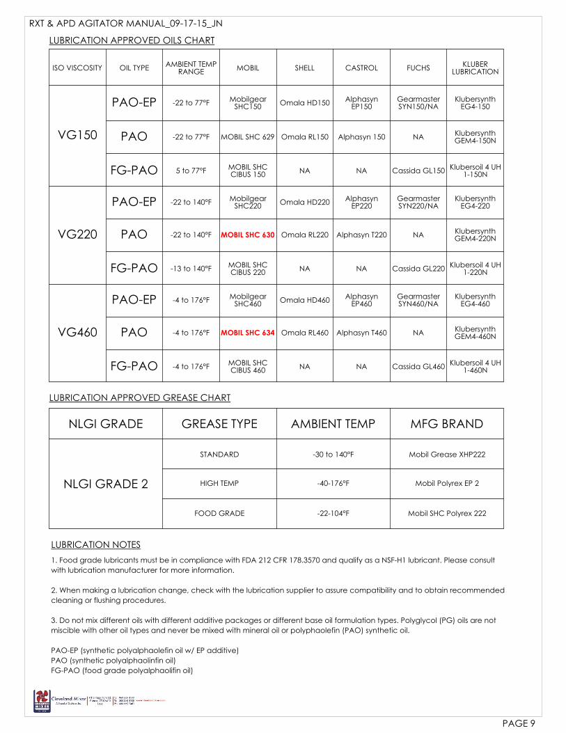
LUBRICATION APPROVED OILS CHART
ISO VISCOSITY OIL TYPEAMBIENT TEMP
RANGEMOBIL SHELL CASTROL FUCHS
KLUBERLUBRICATION
VG150
PAO-EP -22 to 77°F MobilgearSHC150
Omala HD150 AlphasynEP150
GearmasterSYN150/NA
KlubersynthEG4-150
PAO -22 to 77°F MOBIL SHC 629 Omala RL150 Alphasyn 150 NAKlubersynthGEM4-150N
FG-PAO 5 to 77°F MOBIL SHCCIBUS 150
NA NA Cassida GL150 Klubersoil 4 UH1-150N
VG220
PAO-EP -22 to 140°F MobilgearSHC220
Omala HD220 AlphasynEP220
GearmasterSYN220/NA
KlubersynthEG4-220
PAO -22 to 140°F MOBIL SHC 630 Omala RL220 Alphasyn T220 NAKlubersynthGEM4-220N
FG-PAO -13 to 140°FMOBIL SHCCIBUS 220
NA NA Cassida GL220Klubersoil 4 UH
1-220N
VG460
PAO-EP -4 to 176°FMobilgear
SHC460Omala HD460
AlphasynEP460
GearmasterSYN460/NA
KlubersynthEG4-460
PAO -4 to 176°F MOBIL SHC 634 Omala RL460 Alphasyn T460 NA KlubersynthGEM4-460N
FG-PAO -4 to 176°FMOBIL SHCCIBUS 460 NA NA Cassida GL460
Klubersoil 4 UH1-460N
LUBRICATION APPROVED GREASE CHART
NLGI GRADE GREASE TYPE AMBIENT TEMP MFG BRAND
NLGI GRADE 2
STANDARD -30 to 140°F Mobil Grease XHP222
HIGH TEMP -40-176°F Mobil Polyrex EP 2
FOOD GRADE -22-104°F Mobil SHC Polyrex 222
LUBRICATION NOTES
1. Food grade lubricants must be in compliance with FDA 212 CFR 178.3570 and qualify as a NSF-H1 lubricant. Please consult
with lubrication manufacturer for more information.
2. When making a lubrication change, check with the lubrication supplier to assure compatibility and to obtain recommended
cleaning or flushing procedures.
3. Do not mix different oils with different additive packages or different base oil formulation types. Polyglycol (PG) oils are not
miscible with other oil types and never be mixed with mineral oil or polyphaolefin (PAO) synthetic oil.
PAO-EP (synthetic polyalphaolefin oil w/ EP additive)
PAO (synthetic polyalphaolinfin oil)
FG-PAO (food grade polyalphaolifin oil)
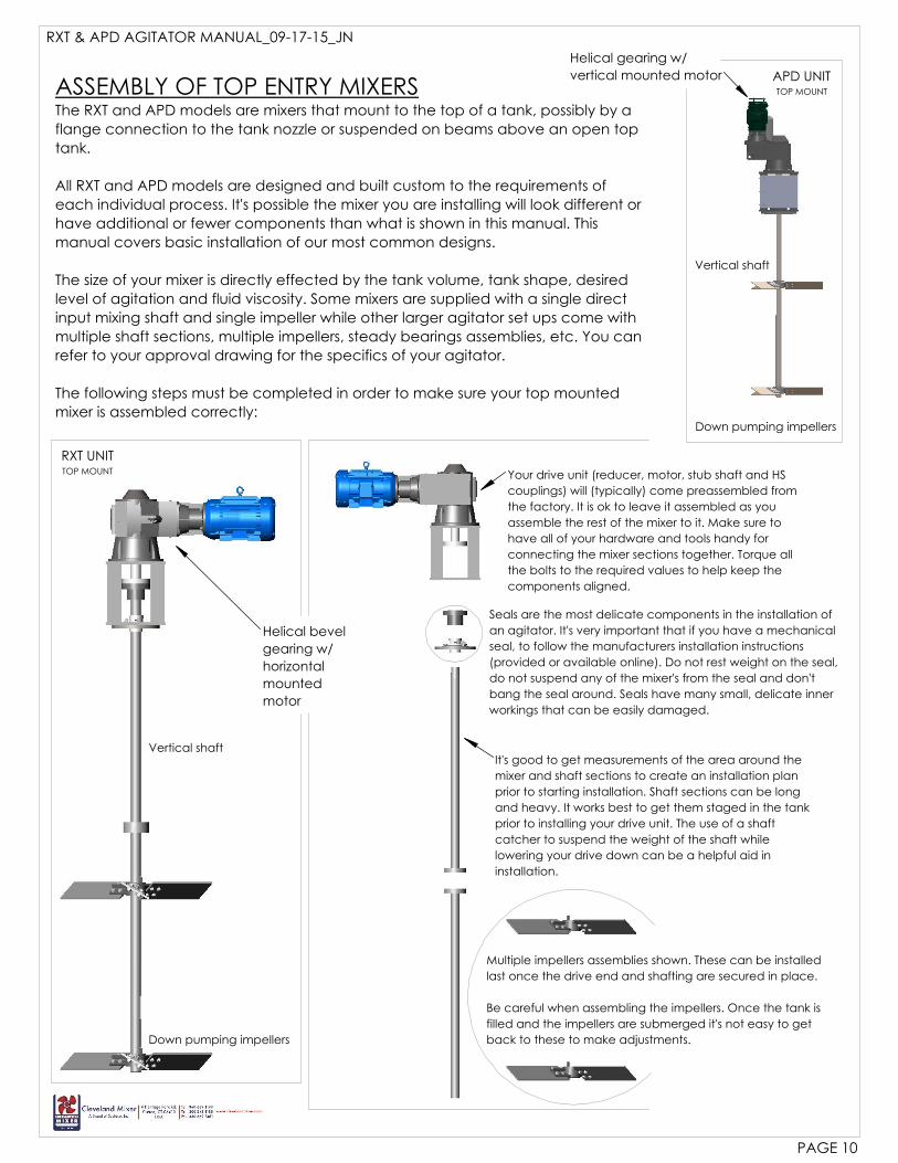
It's good to get measurements of the area around the
mixer and shaft sections to create an installation plan
prior to starting installation. Shaft sections can be long
and heavy. It works best to get them staged in the tank
prior to installing your drive unit. The use of a shaft
catcher to suspend the weight of the shaft while
lowering your drive down can be a helpful aid in
installation.
Your drive unit (reducer, motor, stub shaft and HS
couplings) will (typically) come preassembled from
the factory. It is ok to leave it assembled as you
assemble the rest of the mixer to it. Make sure to
have all of your hardware and tools handy for
connecting the mixer sections together. Torque all
the bolts to the required values to help keep the
components aligned.
ASSEMBLY OF TOP ENTRY MIXERSThe RXT and APD models are mixers that mount to the top of a tank, possibly by a
flange connection to the tank nozzle or suspended on beams above an open top
tank.
All RXT and APD models are designed and built custom to the requirements of
each individual process. It's possible the mixer you are installing will look different or
have additional or fewer components than what is shown in this manual. This
manual covers basic installation of our most common designs.
The size of your mixer is directly effected by the tank volume, tank shape, desired
level of agitation and fluid viscosity. Some mixers are supplied with a single direct
input mixing shaft and single impeller while other larger agitator set ups come with
multiple shaft sections, multiple impellers, steady bearings assemblies, etc. You can
refer to your approval drawing for the specifics of your agitator.
The following steps must be completed in order to make sure your top mounted
mixer is assembled correctly:
RXT UNITTOP MOUNT
Vertical shaft
APD UNITTOP MOUNT
Down pumping impellers
Down pumping impellers
Vertical shaft
Multiple impellers assemblies shown. These can be installed
last once the drive end and shafting are secured in place.
Be careful when assembling the impellers. Once the tank is
filled and the impellers are submerged it's not easy to get
back to these to make adjustments.
Seals are the most delicate components in the installation of
an agitator. It's very important that if you have a mechanical
seal, to follow the manufacturers installation instructions
(provided or available online). Do not rest weight on the seal,
do not suspend any of the mixer's from the seal and don't
bang the seal around. Seals have many small, delicate inner
workings that can be easily damaged.
RXT & APD AGITATOR MANUAL_09-17-15_JN
PAGE 10
Helical gearing w/
vertical mounted motor
Helical bevel
gearing w/
horizontal
mounted
motor
RXT & APD AGITATOR MANUAL_09-17-15_JN
PAGE 11
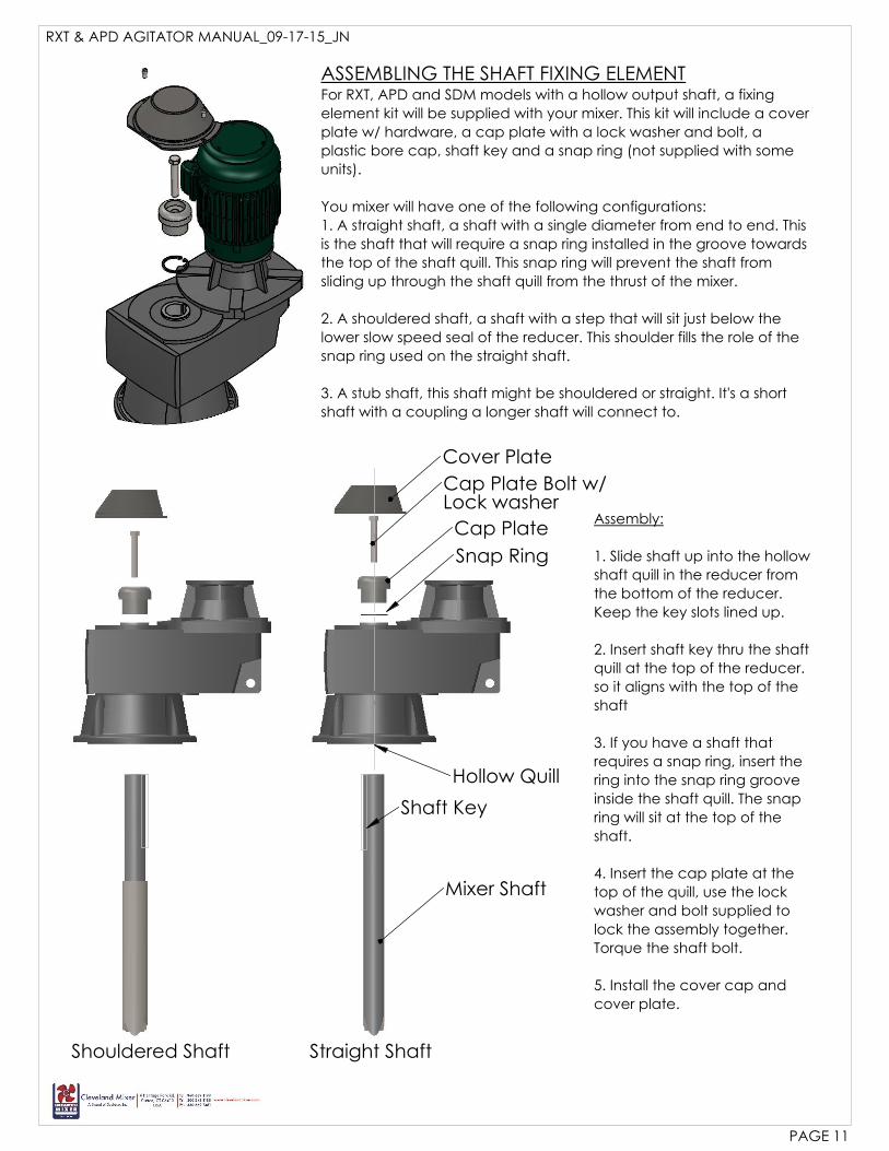
ASSEMBLING THE SHAFT FIXING ELEMENTFor RXT, APD and SDM models with a hollow output shaft, a fixing
element kit will be supplied with your mixer. This kit will include a cover
plate w/ hardware, a cap plate with a lock washer and bolt, a
plastic bore cap, shaft key and a snap ring (not supplied with some
units).
You mixer will have one of the following configurations:
1. A straight shaft, a shaft with a single diameter from end to end. This
is the shaft that will require a snap ring installed in the groove towards
the top of the shaft quill. This snap ring will prevent the shaft from
sliding up through the shaft quill from the thrust of the mixer.
2. A shouldered shaft, a shaft with a step that will sit just below the
lower slow speed seal of the reducer. This shoulder fills the role of the
snap ring used on the straight shaft.
3. A stub shaft, this shaft might be shouldered or straight. It's a short
shaft with a coupling a longer shaft will connect to.
Shouldered Shaft Straight Shaft
Assembly:
1. Slide shaft up into the hollow
shaft quill in the reducer from
the bottom of the reducer.
Keep the key slots lined up.
2. Insert shaft key thru the shaft
quill at the top of the reducer.
so it aligns with the top of the
shaft
3. If you have a shaft that
requires a snap ring, insert the
ring into the snap ring groove
inside the shaft quill. The snap
ring will sit at the top of the
shaft.
4. Insert the cap plate at the
top of the quill, use the lock
washer and bolt supplied to
lock the assembly together.
Torque the shaft bolt.
5. Install the cover cap and
cover plate.
Cover Plate
Cap Plate Bolt w/Lock washer
Cap Plate
Snap Ring
Shaft Key
Mixer Shaft
Hollow Quill
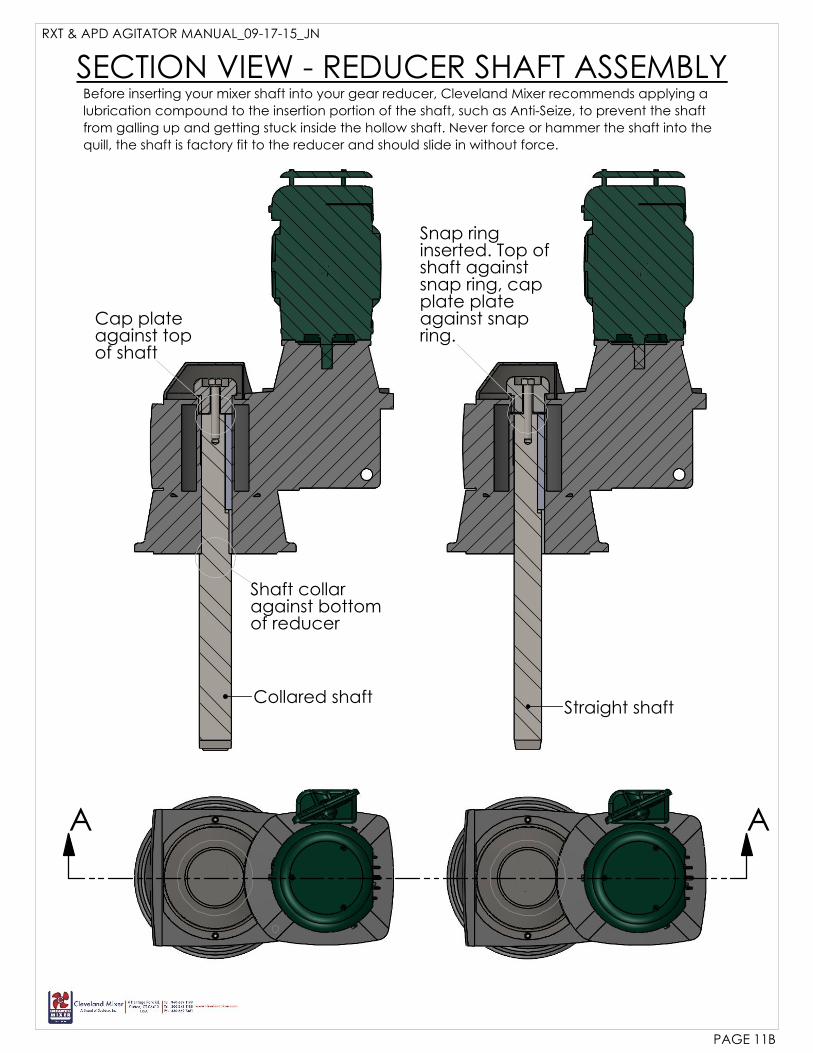
AA
Collared shaftStraight shaft
SECTION VIEW - REDUCER SHAFT ASSEMBLY
Shaft collaragainst bottomof reducer
Cap plateagainst topof shaft
Snap ringinserted. Top ofshaft againstsnap ring, capplate plateagainst snapring.
Before inserting your mixer shaft into your gear reducer, Cleveland Mixer recommends applying a
lubrication compound to the insertion portion of the shaft, such as Anti-Seize, to prevent the shaft
from galling up and getting stuck inside the hollow shaft. Never force or hammer the shaft into the
quill, the shaft is factory fit to the reducer and should slide in without force.
RXT & APD AGITATOR MANUAL_09-17-15_JN
PAGE 11B
RXT & APD AGITATOR MANUAL_09-17-15_JN
PAGE 12
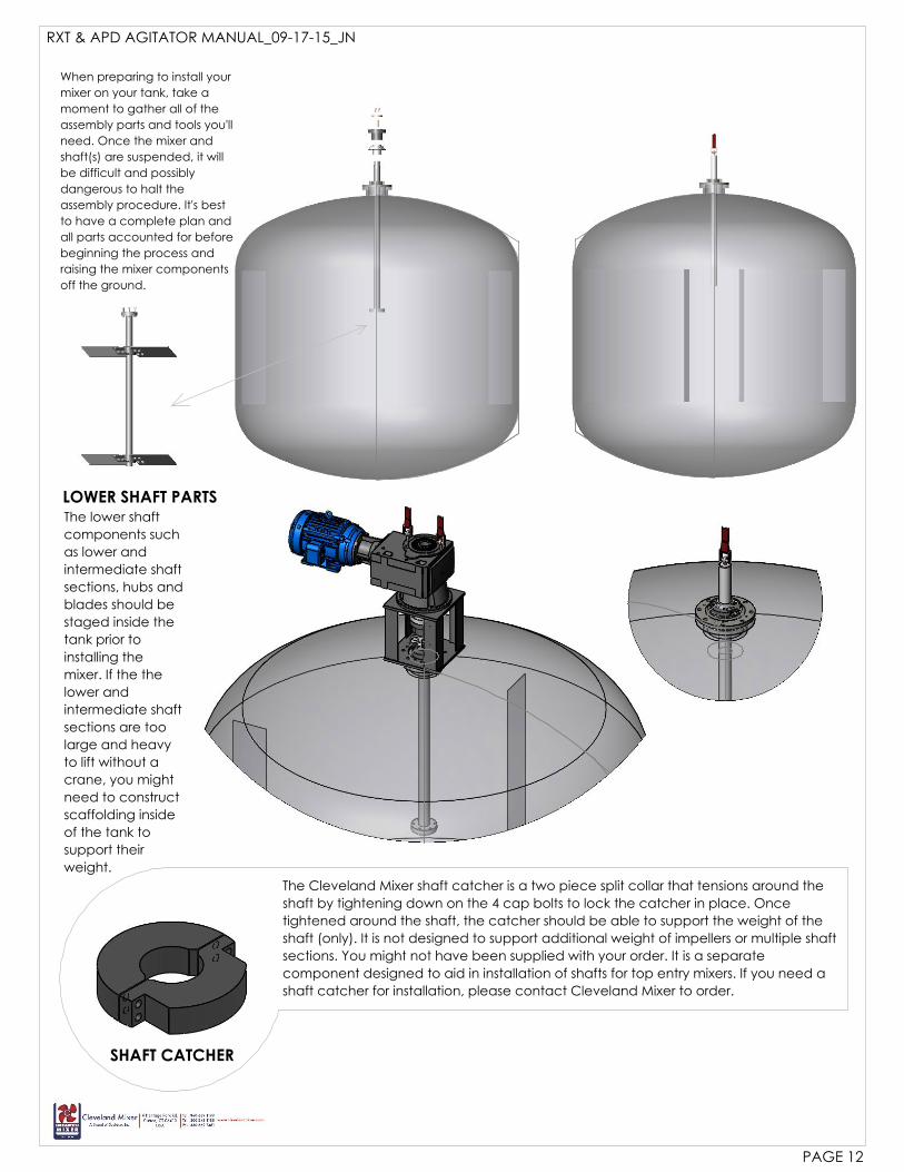
LOWER SHAFT PARTSThe lower shaft
components such
as lower and
intermediate shaft
sections, hubs and
blades should be
staged inside the
tank prior to
installing the
mixer. If the the
lower and
intermediate shaft
sections are too
large and heavy
to lift without a
crane, you might
need to construct
scaffolding inside
of the tank to
support their
weight.
SHAFT CATCHER
The Cleveland Mixer shaft catcher is a two piece split collar that tensions around the
shaft by tightening down on the 4 cap bolts to lock the catcher in place. Once
tightened around the shaft, the catcher should be able to support the weight of the
shaft (only). It is not designed to support additional weight of impellers or multiple shaft
sections. You might not have been supplied with your order. It is a separate
component designed to aid in installation of shafts for top entry mixers. If you need a
shaft catcher for installation, please contact Cleveland Mixer to order.
When preparing to install your
mixer on your tank, take a
moment to gather all of the
assembly parts and tools you'll
need. Once the mixer and
shaft(s) are suspended, it will
be difficult and possibly
dangerous to halt the
assembly procedure. It's best
to have a complete plan and
all parts accounted for before
beginning the process and
raising the mixer components
off the ground.
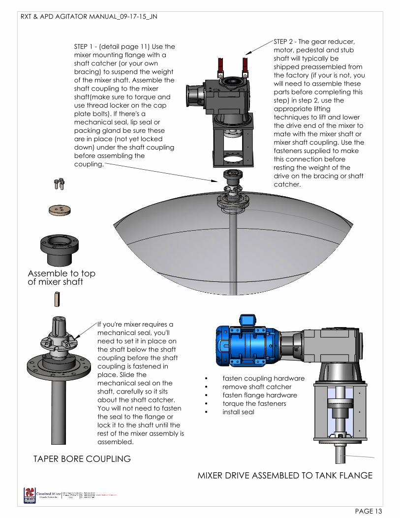
STEP 1 - (detail page 11) Use the
mixer mounting flange with a
shaft catcher (or your own
bracing) to suspend the weight
of the mixer shaft. Assemble the
shaft coupling to the mixer
shaft(make sure to torque and
use thread locker on the cap
plate bolts). If there's a
mechanical seal, lip seal or
packing gland be sure these
are in place (not yet locked
down) under the shaft coupling
before assembling the
coupling.
STEP 2 - The gear reducer,
motor, pedestal and stub
shaft will typically be
shipped preassembled from
the factory (if your is not, you
will need to assemble these
parts before completing this
step) in step 2, use the
appropriate lifting
techniques to lift and lower
the drive end of the mixer to
mate with the mixer shaft or
mixer shaft coupling. Use the
fasteners supplied to make
this connection before
resting the weight of the
drive on the bracing or shaft
catcher.
fasten coupling hardware•
remove shaft catcher•
fasten flange hardware•
torque the fasteners•
install seal•
TAPER BORE COUPLING
Assemble to topof mixer shaft
MIXER DRIVE ASSEMBLED TO TANK FLANGE
RXT & APD AGITATOR MANUAL_09-17-15_JN
PAGE 13
If you're mixer requires a
mechanical seal, you'll
need to set it in place on
the shaft below the shaft
coupling before the shaft
coupling is fastened in
place. Slide the
mechanical seal on the
shaft, carefully so it sits
about the shaft catcher.
You will not need to fasten
the seal to the flange or
lock it to the shaft until the
rest of the mixer assembly is
assembled.
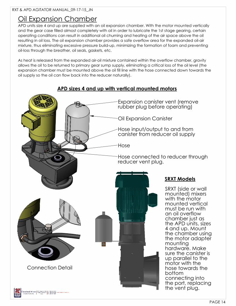
Oil Expansion Canister
Hose input/output to and fromcanister from reducer oil supply
Hose
Hose connected to reducer throughreducer vent plug.
Expansion canister vent (removerubber plug before operating)
RXT & APD AGITATOR MANUAL_09-17-15_JN
PAGE 14
Oil Expansion ChamberAPD units size 4 and up are supplied with an oil expansion chamber. With the motor mounted vertically
and the gear case filled almost completely with oil in order to lubricate the 1st stage gearing, certain
operating conditions can result in additional oil churning and heating of the air space above the oil
resulting in oil loss. The oil expansion chamber provides a safe overflow area for the expanded oil-air
mixture, thus eliminating excessive pressure build-up, minimizing the formation of foam and preventing
oil-loss through the breather, oil seals, gaskets, etc.
As heat is released from the expanded air-oil mixture contained within the overflow chamber, gravity
allows the oil to be returned to primary gear sump supply, eliminating a critical loss of the oil level (the
expansion chamber must be mounted above the oil fill line with the hose connected down towards the
oil supply so the oil can flow back into the reducer naturally).
APD sizes 4 and up with vertical mounted motors
Connection Detail
SRXT (side or wallmounted) mixerswith the motormounted verticalmust be run withan oil overflowchamber just asthe APD units, sizes4 and up. Mountthe chamber usingthe motor adaptermountinghardware. Makesure the canister isup parallel to themotor with thehose towards thebottomconnecting intothe port, replacingthe vent plug.
SRXT Models

AUTO LUBRICATOR CANISTER (KIT)P/N APD-28301000
COVER PLATE
HARDWARE
ACTIVATION KEY
Prior to starting your mixer: screw in Auto-Lubricator activation key and turn itclockwise until the round plastic ring snapsoff. It's a good idea to record the date ofactivation so you know when to replacethe canister.
Once the canister is activated, replacethe cover plate and secure it to the motoradapter.
AUTO LUBRICATOR ACTIVATION
If you have an APD mixer model with a motor,
frame size 250 or larger, the input adapter will
require an auto-lubricator canister to lubricate the
input adapter bearing.
Your mixer will come supplied with a canister
factory installed. You'll need to activate the
lubricator canister prior to starting the mixer.
An auto-lubricator canister cartridge has a one
year life span. After one year of use you will need
to replace the canister. You can contact
Cleveland Mixer for replacement canisters.
EXPLOSION OF AUTO LUBRICATOR ASSEMBLY
ACTIVATION KEY
RXT & APD AGITATOR MANUAL_09-17-15_JN
PAGE 15
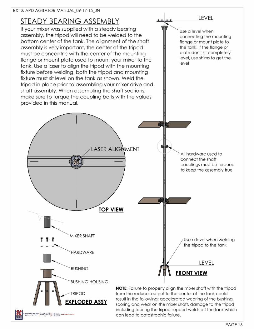
All hardware used to
connect the shaft
couplings must be torqued
to keep the assembly true
Use a level when
connecting the mounting
flange or mount plate to
the tank. If the flange or
plate don't sit completely
level, use shims to get the
level
Use a level when welding
the tripod to the tank
LASER ALIGNMENT
MIXER SHAFT
HARDWARE
BUSHING
BUSHING HOUSING
TRIPOD
RXT & APD AGITATOR MANUAL_09-17-15_JN
PAGE 16
STEADY BEARING ASSEMBLYLEVEL
LEVEL
If your mixer was supplied with a steady bearingassembly, the tripod will need to be welded to thebottom center of the tank. The alignment of the shaftassembly is very important, the center of the tripodmust be concentric with the center of the mountingflange or mount plate used to mount your mixer to thetank. Use a laser to align the tripod with the mountingfixture before welding, both the tripod and mountingfixture must sit level on the tank as shown. Weld thetripod in place prior to assembling your mixer drive andshaft assembly. When assembling the shaft sections,make sure to torque the coupling bolts with the valuesprovided in this manual.
TOP VIEW
FRONT VIEW
EXPLODED ASSY
NOTE: Failure to properly align the mixer shaft with the tripod
from the reducer output to the center of the tank could
result in the following: accelerated wearing of the bushing,
scoring and wear on the mixer shaft, damage to the tripod
including tearing the tripod support welds off the tank which
can lead to catastrophic failure.
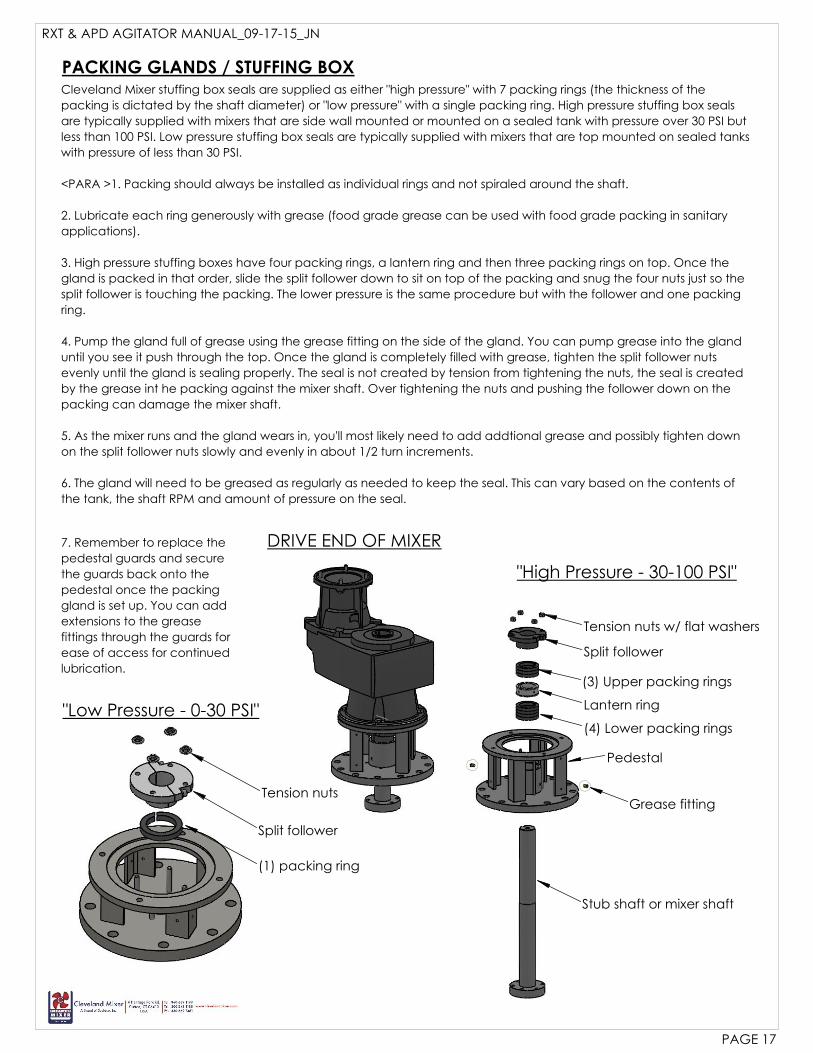
(1) packing ring
Split follower
Tension nuts
PACKING GLANDS / STUFFING BOX
"High Pressure - 30-100 PSI"
"Low Pressure - 0-30 PSI"
Cleveland Mixer stuffing box seals are supplied as either "high pressure" with 7 packing rings (the thickness of the
packing is dictated by the shaft diameter) or "low pressure" with a single packing ring. High pressure stuffing box seals
are typically supplied with mixers that are side wall mounted or mounted on a sealed tank with pressure over 30 PSI but
less than 100 PSI. Low pressure stuffing box seals are typically supplied with mixers that are top mounted on sealed tanks
with pressure of less than 30 PSI.
<PARA >1. Packing should always be installed as individual rings and not spiraled around the shaft.
2. Lubricate each ring generously with grease (food grade grease can be used with food grade packing in sanitary
applications).
3. High pressure stuffing boxes have four packing rings, a lantern ring and then three packing rings on top. Once the
gland is packed in that order, slide the split follower down to sit on top of the packing and snug the four nuts just so the
split follower is touching the packing. The lower pressure is the same procedure but with the follower and one packing
ring.
4. Pump the gland full of grease using the grease fitting on the side of the gland. You can pump grease into the gland
until you see it push through the top. Once the gland is completely filled with grease, tighten the split follower nuts
evenly until the gland is sealing properly. The seal is not created by tension from tightening the nuts, the seal is created
by the grease int he packing against the mixer shaft. Over tightening the nuts and pushing the follower down on the
packing can damage the mixer shaft.
5. As the mixer runs and the gland wears in, you'll most likely need to add addtional grease and possibly tighten down
on the split follower nuts slowly and evenly in about 1/2 turn increments.
6. The gland will need to be greased as regularly as needed to keep the seal. This can vary based on the contents of
the tank, the shaft RPM and amount of pressure on the seal.
DRIVE END OF MIXER7. Remember to replace the
pedestal guards and secure
the guards back onto the
pedestal once the packing
gland is set up. You can add
extensions to the grease
fittings through the guards for
ease of access for continued
lubrication.
RXT & APD AGITATOR MANUAL_09-17-15_JN
PAGE 17
Tension nuts w/ flat washers
Split follower
(3) Upper packing rings
Lantern ring
(4) Lower packing rings
Pedestal
Stub shaft or mixer shaft
Grease fitting
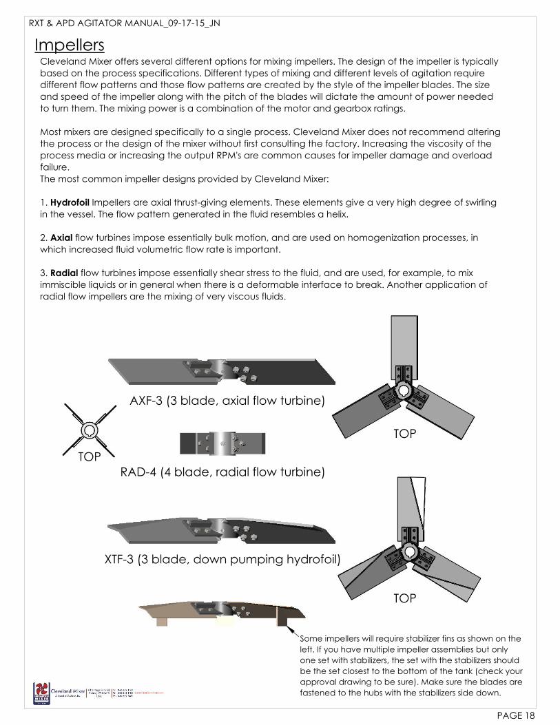
Some impellers will require stabilizer fins as shown on the
left. If you have multiple impeller assemblies but only
one set with stabilizers, the set with the stabilizers should
be the set closest to the bottom of the tank (check your
approval drawing to be sure). Make sure the blades are
fastened to the hubs with the stabilizers side down.
RXT & APD AGITATOR MANUAL_09-17-15_JN
PAGE 18
Impellers
AXF-3 (3 blade, axial flow turbine)
RAD-4 (4 blade, radial flow turbine)
XTF-3 (3 blade, down pumping hydrofoil)
Cleveland Mixer offers several different options for mixing impellers. The design of the impeller is typically
based on the process specifications. Different types of mixing and different levels of agitation require
different flow patterns and those flow patterns are created by the style of the impeller blades. The size
and speed of the impeller along with the pitch of the blades will dictate the amount of power needed
to turn them. The mixing power is a combination of the motor and gearbox ratings.
Most mixers are designed specifically to a single process. Cleveland Mixer does not recommend altering
the process or the design of the mixer without first consulting the factory. Increasing the viscosity of the
process media or increasing the output RPM's are common causes for impeller damage and overload
failure.
The most common impeller designs provided by Cleveland Mixer:
1. Hydrofoil Impellers are axial thrust-giving elements. These elements give a very high degree of swirling
in the vessel. The flow pattern generated in the fluid resembles a helix.
2. Axial flow turbines impose essentially bulk motion, and are used on homogenization processes, in
which increased fluid volumetric flow rate is important.
3. Radial flow turbines impose essentially shear stress to the fluid, and are used, for example, to mix
immiscible liquids or in general when there is a deformable interface to break. Another application of
radial flow impellers are the mixing of very viscous fluids.
TOP
TOP
TOP

Male register
Female register
Nuts & Lock Washers
Set screw
Hub marked "TOP" side up
Bolts - lubricate before fastening
Bolt blades to bottom of hub ear
Hub
Hook end of Gib Key
Dimple for set screw
Impellers, Shafts & CouplingsOnce the drive end of your mixer is installed on the tank, it's time to connect your shaft couplings (if your
mixer has multiple shaft sections) and assemble the impellers.
Before beginning this stage of the assembly, check to make sure you have all of the components,
hardware and tools you'll need to correctly connect the shaft couplings and impeller assemblies. You can
refer to your assembly approval drawing for a list of all of the parts associated with your mixer.
Cleveland Mixer recommends using thread locking compound on all connection hardware. A calibrated
torque wrench is required to keep balance in the connections and to ensure the connection bolts are
stretched and tightened so they won't come loose during operation.
SHAFT COUPLINGS1. Each shaft coupling connection will have a male and female register. Check these registers for dirt, dings and dents
that might have accrued during shipment or staging of these components. For proper alignment, it's important these
registers have a clean connection.
2. Once the registers are mated, insert the pre-lubricated connection bolts. Each set of hardware will include a bolt,
split spring lock washer and a nut. You can check your assembly drawing for the wetted parts material of construction
to make sure you're using the correct hardware. The hardware will be either 316L stainless steel or zinc. Stainless steel
hardware should be used in sanitary or corrosive applications.
3. Add a few drops of thread locker and hand tighten the nuts to the lock washers. Use the torque chart from this
manual to find the torque value for the size of the bolt. Torque the nuts down each of the nuts down to the same
value to ensure proper alignment of the coupling connection.
IMPELLER ASSEMBLYAssemble the impellers using the same procedure described above to tighten the connection hardware.
1. Check the center bore of the hub to make sure it's clean from dings, dents, scratches and dirt. The bore tolerance
might be as close as +/- .005", you don't want to force the hub on the shaft. Forcing can cause it to gall up and get
stuck on the shaft. Check the hub for the marking "TOP" make sure that side of the hub slides up towards the mixer
drive. The hub should slide up the shaft nice and easy with minimal assistance beyond supporting it's weight.
2. Starting with the top hub (if you have multiple impellers) slide the hub up over the key slot.
3. Insert the key into the key slot with the gib end down. You should be able to slide the hub down and let it rest on the
key without a fastener.
4. Add a few drops of thread locking compound or fastener lubricant and torque the set screw to the key. The set
screw should line up with a dimple in the center of the key.
5. Fasten the blades to the bottom of the hub ears. Blades with stabilizer fins should have the fin side down. Double
check this assembly before operating the mixer. Operating the mixer with the blades or hubs on backwards or upside
down can cause catastrophic damage to the mixer.
RXT & APD AGITATOR MANUAL_09-17-15_JN
PAGE 19
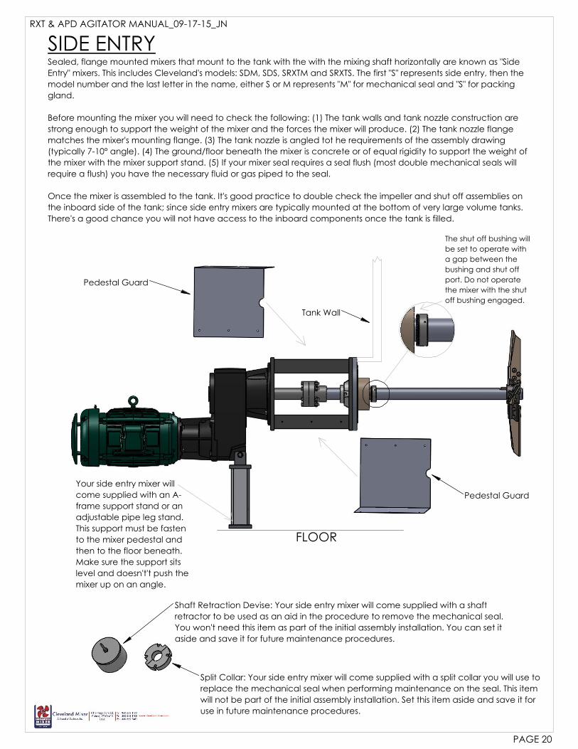
Split Collar: Your side entry mixer will come supplied with a split collar you will use to
replace the mechanical seal when performing maintenance on the seal. This item
will not be part of the initial assembly installation. Set this item aside and save it for
use in future maintenance procedures.
The shut off bushing will
be set to operate with
a gap between the
bushing and shut off
port. Do not operate
the mixer with the shut
off bushing engaged.
Shaft Retraction Devise: Your side entry mixer will come supplied with a shaft
retractor to be used as an aid in the procedure to remove the mechanical seal.
You won't need this item as part of the initial assembly installation. You can set it
aside and save it for future maintenance procedures.
Your side entry mixer will
come supplied with an A-
frame support stand or an
adjustable pipe leg stand.
This support must be fasten
to the mixer pedestal and
then to the floor beneath.
Make sure the support sits
level and doesn't't push the
mixer up on an angle.
Pedestal Guard
Pedestal Guard
Tank Wall
RXT & APD AGITATOR MANUAL_09-17-15_JN
PAGE 20
FLOOR
SIDE ENTRYSealed, flange mounted mixers that mount to the tank with the with the mixing shaft horizontally are known as "Side
Entry" mixers. This includes Cleveland's models: SDM, SDS, SRXTM and SRXTS. The first "S" represents side entry, then the
model number and the last letter in the name, either S or M represents "M" for mechanical seal and "S" for packing
gland.
Before mounting the mixer you will need to check the following: (1) The tank walls and tank nozzle construction are
strong enough to support the weight of the mixer and the forces the mixer will produce. (2) The tank nozzle flange
matches the mixer's mounting flange. (3) The tank nozzle is angled tot he requirements of the assembly drawing
(typically 7-10° angle). (4) The ground/floor beneath the mixer is concrete or of equal rigidity to support the weight of
the mixer with the mixer support stand. (5) If your mixer seal requires a seal flush (most double mechanical seals will
require a flush) you have the necessary fluid or gas piped to the seal.
Once the mixer is assembled to the tank. It's good practice to double check the impeller and shut off assemblies on
the inboard side of the tank; since side entry mixers are typically mounted at the bottom of very large volume tanks.
There's a good chance you will not have access to the inboard components once the tank is filled.
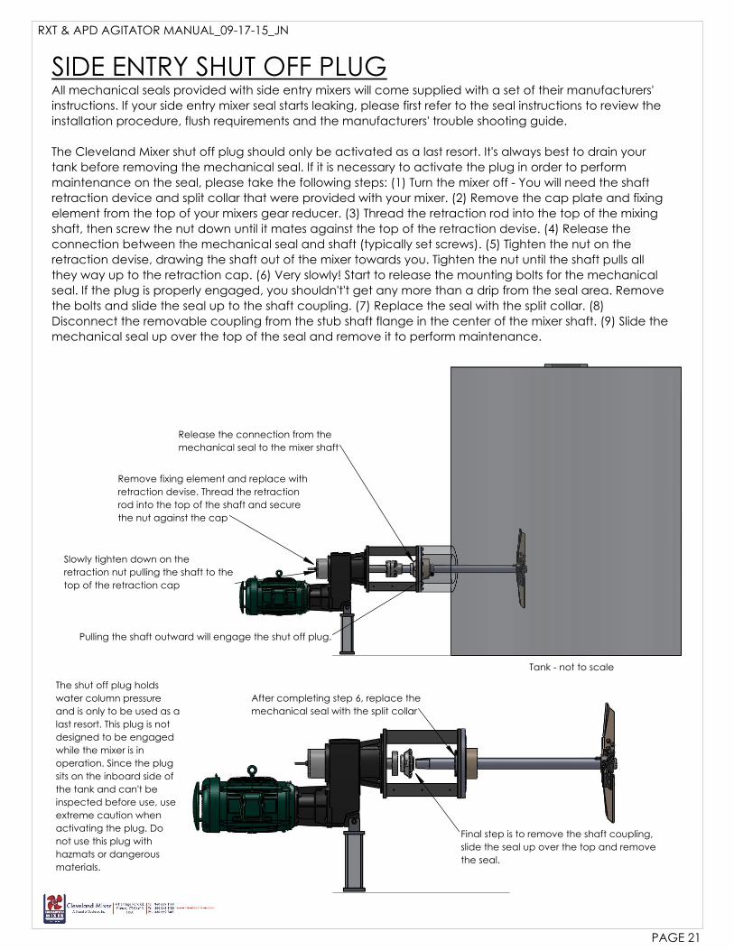
After completing step 6, replace the
mechanical seal with the split collar
Final step is to remove the shaft coupling,
slide the seal up over the top and remove
the seal.
Remove fixing element and replace with
retraction devise. Thread the retraction
rod into the top of the shaft and secure
the nut against the cap
Release the connection from the
mechanical seal to the mixer shaft
Slowly tighten down on the
retraction nut pulling the shaft to the
top of the retraction cap
Pulling the shaft outward will engage the shut off plug.
SIDE ENTRY SHUT OFF PLUGAll mechanical seals provided with side entry mixers will come supplied with a set of their manufacturers'
instructions. If your side entry mixer seal starts leaking, please first refer to the seal instructions to review the
installation procedure, flush requirements and the manufacturers' trouble shooting guide.
The Cleveland Mixer shut off plug should only be activated as a last resort. It's always best to drain your
tank before removing the mechanical seal. If it is necessary to activate the plug in order to perform
maintenance on the seal, please take the following steps: (1) Turn the mixer off - You will need the shaft
retraction device and split collar that were provided with your mixer. (2) Remove the cap plate and fixing
element from the top of your mixers gear reducer. (3) Thread the retraction rod into the top of the mixing
shaft, then screw the nut down until it mates against the top of the retraction devise. (4) Release the
connection between the mechanical seal and shaft (typically set screws). (5) Tighten the nut on the
retraction devise, drawing the shaft out of the mixer towards you. Tighten the nut until the shaft pulls all
they way up to the retraction cap. (6) Very slowly! Start to release the mounting bolts for the mechanical
seal. If the plug is properly engaged, you shouldn't't get any more than a drip from the seal area. Remove
the bolts and slide the seal up to the shaft coupling. (7) Replace the seal with the split collar. (8)
Disconnect the removable coupling from the stub shaft flange in the center of the mixer shaft. (9) Slide the
mechanical seal up over the top of the seal and remove it to perform maintenance.
The shut off plug holds
water column pressure
and is only to be used as a
last resort. This plug is not
designed to be engaged
while the mixer is in
operation. Since the plug
sits on the inboard side of
the tank and can't be
inspected before use, use
extreme caution when
activating the plug. Do
not use this plug with
hazmats or dangerous
materials.
Tank - not to scale
RXT & APD AGITATOR MANUAL_09-17-15_JN
PAGE 21

RXT & APD AGITATOR MANUAL_09-17-15_JN