installation, operation maintenance manual/media/resources/virgo/manual... · installation,...
TRANSCRIPT
Page 1 of 28
INSTALLATION, OPERATION &
MAINTENANCE MANUAL
FLOATING AND TRUNNION MOUNTED BALL VALVE
VIRGO ENGINEERS LIMITED VIRGO VALVES & CONTROLS LIMITED (An ISO 9001, PED, API Certified Company) (An ISO 9001, PED, API Certified Company)
Regd. Office: Works: 277, Hinjewadi Phase II, Maan (Mulshi), 277, Hinjewadi Phase II, Maan (Mulshi), Pune – 411 057, INDIA. Pune – 411 057, INDIA Phone: +91-20-66744000. Phone: +91-20-66744000. Fax: +91-20-66744021. Fax: +91-20-66744021. E-mail: [email protected] E-mail: [email protected] Website: www.virgoengineers.com Website: www.virgoengineers.com

Page 2 of 28
Table of Contents
Sr. No. General Instructions Page No.
1. Introduction 3
2. Transportation, Reception and Storage 3
3. Do’s and Don’ts 4
4. Installation 5
5. Possible misuse of ball valve 7
6. Operation of the valve(s) 8
7. Guide lines for assembly and disassembly of gear box on valve 9
8. Guide lines for reorientation of gear box on valve 11
9. Preventive Maintenance 12
10. Trouble Shooting 13
11. Ordering the Spares 14
12. General Disassembly and Assembly Instructions for: 14
I) Trunnion Mounted Ball Valves. II) Floating ball valve
12.I.A Disassembly For Trunnion Mounted Ball Valves (Two Piece Design/Three Piece Design)-Trunnion Ball Valve
15
12.I.B Reassembly For Trunnion Mounted Ball Valves (Two Piece Design/Three Piece Design)-Trunnion Ball Valve
16
12.I.C Exploded View- Trunnion Ball Valve - Two & Three Piece Design 17
12.I.D Disassembly For Trunnion Mounted Ball Valves (Two Piece Design/Three Piece Design)-Trunnion Plate Valve
18
12.I.E Reassembly For Trunnion Mounted Ball Valves (Two Piece Design/Three Piece Design)-Trunnion Plate Valve
19
12.I.F Exploded View- Trunnion Ball Valve – Two & Three Piece Design-Trunnion Plate Ball Valve
21
12.II.A Disassembly for Floating Ball Valve (Two Piece Design/Three Piece Design)
22
12.II.B Reassembly for Floating Ball Valve (Two Piece Design/Three Piece Design)
22
12.II.C Exploded Views For Floating Ball Valves-Two Piece Design-Lever Operated.
23
12.II.D Exploded Views For Floating Ball Valves-Three Piece Design 24
12.II.E Exploded Views For Floating Ball Valves-Two Piece Design- Gear Operated
25
Table: A Recommended Tightening Torque for bolting 26 Table: B Recommended Tightening Torque for NPT threads 26
13.0 Address for correspondence : Works 27 13.I Address for correspondence : Branch offices 28
Installation, Operation & Maintenance Manual
Page 3 of 28
1.0 INTRODUCTION:
Scope - The manual is provided to ensure proper installation, operation & maintenance for the Ball valves
manufactured and supplied by Virgo Group of Companies. The valves are identified by marking on
the body or on a nameplate or both.
VIRGO ENGINEERS LTD
PUNE, (INDIA)
1.1 Identification of Valve
2.0 TRANSPORTATION, RECEPTION AND STORAGE:
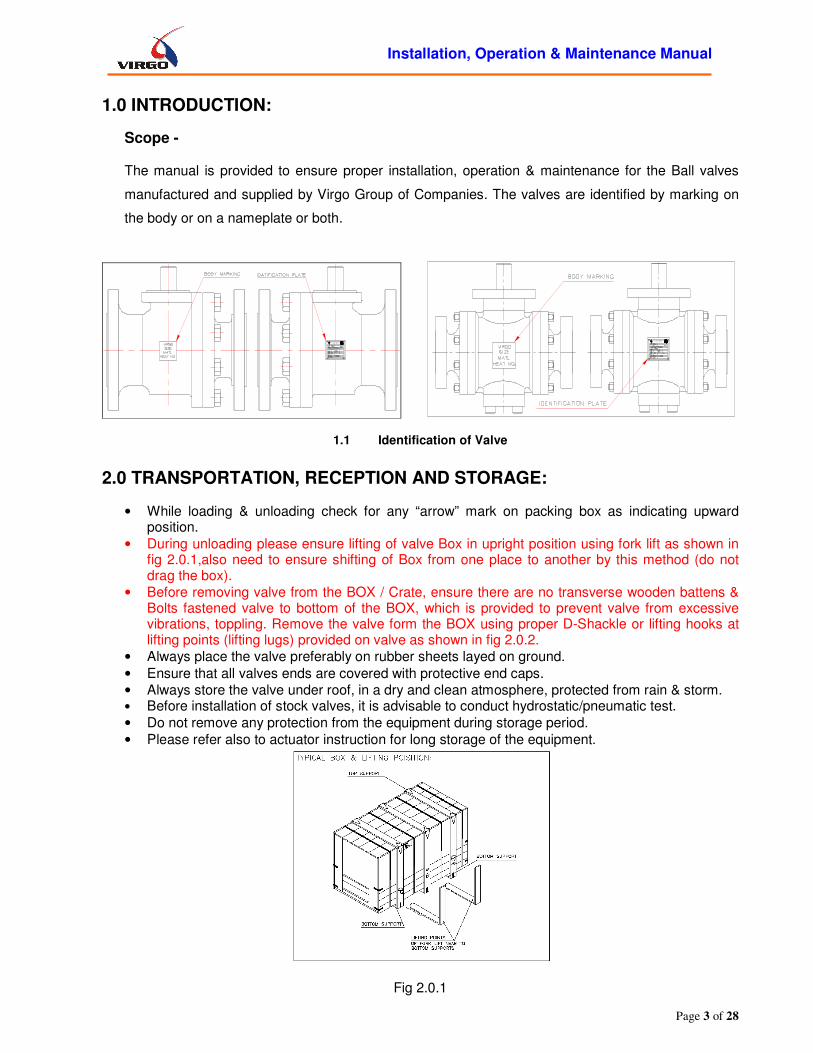
• While loading & unloading check for any “arrow” mark on packing box as indicating upward position.
• During unloading please ensure lifting of valve Box in upright position using fork lift as shown in fig 2.0.1,also need to ensure shifting of Box from one place to another by this method (do not drag the box).
• Before removing valve from the BOX / Crate, ensure there are no transverse wooden battens & Bolts fastened valve to bottom of the BOX, which is provided to prevent valve from excessive vibrations, toppling. Remove the valve form the BOX using proper D-Shackle or lifting hooks at lifting points (lifting lugs) provided on valve as shown in fig 2.0.2.
• Always place the valve preferably on rubber sheets layed on ground.
• Ensure that all valves ends are covered with protective end caps.
• Always store the valve under roof, in a dry and clean atmosphere, protected from rain & storm. • Before installation of stock valves, it is advisable to conduct hydrostatic/pneumatic test.
• Do not remove any protection from the equipment during storage period.
• Please refer also to actuator instruction for long storage of the equipment.
Fig 2.0.1
PUNE, (INDIA)
VIRGO ENGINEERS LTD

Installation, Operation & Maintenance Manual
Page 4 of 28
Fig 2.0.2
2.1 INSPECTION AND HANDLING OF THE EQUIPMENT
• Identify the equipment contained using the copy of the packing list fixed to the case.
• If a tag number is specified by the customer, identify the valves using tag number stamped on the manufacturer plate.
• Visually inspect all the valves to assure that they have not been damaged during the transport.
• In case of paint damaging, touch-up the damaged painted surface.
• Do not remove any protection from the valve (end flanges, stem connection, etc.), until just before the installation in order to assure maximum protection to valve internal parts and coupling surfaces.
• If the valve is supplied with an operator (gearbox or actuator) already installed, always use valve lifting lugs to lift the complete equipment; do not use operator lifting points to handle the valve.
• The valves are shipped in the fully open position (with exception of a fail spring close actuator installed).
• Always keep the valves in fully open or fully closed position (0°- 90°).
• If the valve is supplied with an actuator, please keep plugged every pneumatic, electrical or hydraulic connection until just before the installation (refer to specific actuator instructions for further information).
• During handling pay particular attention to the valve ends in order to avoid any mechanical damage of sealing surfaces or butt weld faces (as applicable).
• For valve handling always use straps sized to the weight that has to be lifted; do not use chains or hooks in contact with the machined surfaces.
3.0 DO’s AND DON’Ts:
Do’s - • It is recommended always to use the Installation, Operation & Maintenance Manual before
installing, operating or repairing of any Ball Valve(s).
• Use specified / recommended MOC (Material of construction) for specified application.
• Before installation of “Virgo Made” standard valve, it is advised for user to ascertain the
compatibility of the material.
Installation, Operation & Maintenance Manual
Page 5 of 28
• Periodically ensure the tightness of Body-Adapter joint bolting, operatability & the electrical
continuity of the valve.
• Always use dry, moisture free air while opening the valve with pneumatic actuator or for
cleaning purposes.
• Always use Personnel Protective Equipment while working with cryogenic/high temp
applications.
• Ensure that thorough ventilation is provided while working on the close equipment for
oxygen transfer.
• Ensure that the end protections are removed before installation of valve in line.
Don’ts - • Do not drag the valve on bare floor.
• Do not try to rectify the valve leakage by reworking of seats. Leaking seats have to be
replaced with the new Virgo genuine seats.
• Do not allow any such process, which may generate spark, particularly working in H2 or O2
service line or any such inflammable fluids.
• Do not allow dirt, scales, oil or grease to flow through valve & pipeline for oxygen service.
• Do not allow to replace (even temporarily) the pressure-relieving device, which is installed,
for its intended use by a threaded blind plug.
• Do not touch the valve & accessories without suitable personnel protective equipment if the
temperature in application is high or low.
• Do not inhale the cold gases / fumes for long duration while working with cryogenic liquids.
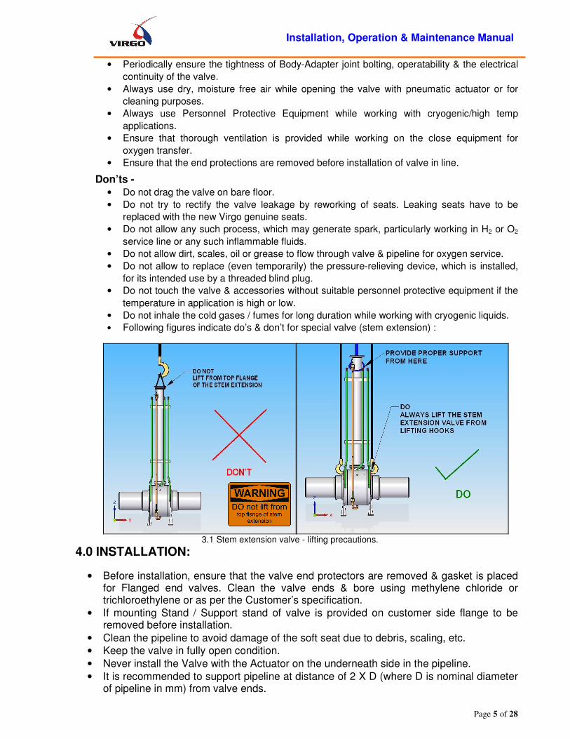
• Following figures indicate do’s & don’t for special valve (stem extension) :
3.1 Stem extension valve - lifting precautions.
4.0 INSTALLATION:
• Before installation, ensure that the valve end protectors are removed & gasket is placed for Flanged end valves. Clean the valve ends & bore using methylene chloride or trichloroethylene or as per the Customer’s specification.
• If mounting Stand / Support stand of valve is provided on customer side flange to be removed before installation.
• Clean the pipeline to avoid damage of the soft seat due to debris, scaling, etc.
• Keep the valve in fully open condition.
• Never install the Valve with the Actuator on the underneath side in the pipeline.
• It is recommended to support pipeline at distance of 2 X D (where D is nominal diameter of pipeline in mm) from valve ends.

Installation, Operation & Maintenance Manual
Page 6 of 28
• If Mounting stands are mounted on Valve end flanges, they should be removed before installation.
4.1 Avoid this mounting position 4.2 Supporting of the valve
While Installing for:
I. Flanged End Valves -
• Don’t over tighten the joint bolting.
• Refer Table: A on page no.28 for recommended tightening torque for bolts, nuts.
II. Weld End Valves - • Don’t allow temperature of the valve body seat area to exceed 200°F (94°C). To check the
temperature, use thermal chalks. (Ref. Fig.4.6 & 4.7)
a) Butt Weld End Valves -
• A proper alignment & a gap ‘g’ as shown in figure 4.3 to get full penetration of weld upto root.
b) Socket-Weld End Valves - • Ensure for proper alignment & a minimum gap of 1.6 mm between the pipe end face and the
socket weld ends as shown in Figure 4.4. • While installing unidirectional valve in pipeline, check for the flow direction mark on valve
body.
4.3 Minimum gap for butt weld end
• Figures 4.5,4.6, 4.7 are of three-piece socket weld end valves showing typical
exploded view, it’s welding to the pipeline & in line maintenance when the pipeline is shut down respectively.

Installation, Operation & Maintenance Manual
Page 7 of 28
FILLET WELDING
SOCKET WELD END
BODY ADAPTER
0.06" TO 0.08" GAP (APPROX)
X min. = 1.25T
PIPE LINE
4.4 welding socket weld end valve to pipe line 4.5 three piece socket weld end valve exploded view
4.6 Virgo make 3-piece ball valve supplied 4.7 In line maintenance of 3-piece socket weld with pup piece (welding procedure) end valve
5.0 Possible misuse of ball valve
Sr. No. Possible Misuse Recommended / Proposed actions
1 Exceeding the limits of the Pressure / Temperature as agreed between Virgo and Customer (Ref. P.O)
1. Appropriate Cautions, Do’s, and Don’ts to be addressed in Installation, Operation, and Maintenance Manual.
2. Service/Marketing/Design engineer to confirm the technical details as per P.O., as and when visit is made to Customers site.
3. Name plate/Body marking details should indicate the Technical details.
2 Use of different application fluid. (Not as specified in Valve Data Sheet/P.O.)
1. Appropriate Cautions, Do’s, and Don’ts to be addressed in Installation, Operation, and Maintenance Manual.
2. Service/Marketing/Design engineer to confirm the technical details as per P.O., as and when visit is made to Customers site.
3. Name plate/Body marking details should indicate the Technical details.

Installation, Operation & Maintenance Manual
Page 8 of 28
3 Lock Open/Close Arrangement
1. Certain applications must be provided with lock open/close arrangement. To be provided in consultation with Customer or based on experience in that field.
2. If possible, provision for lock open/close arrangement to be made at design stage.
4 Upside down mounting of Ball Valves.
1. Upside down mounting of Valve to be avoided. 2. Mounting of Valves to be checked by
Service/Marketing/Design engineer as per P.O., as and when visit is made to Customers site.
3. Appropriate Cautions, Do’s, and Don’ts to be addressed in Installation, Operation, and Maintenance Manual.
5 Wrong installation in case of uni-directional Valves
1. Flow Direction to be marked on the Valve. Necessary provision to be made at design stage.
2. BOM / Check sheet should include the necessary instructions.
6 Making use of Virgo Valve for other purpose by removing the Name plate/Body marking details.
1. Provision for affixing the nameplate to the Valve to be made. As cast body markings to be provided on the Valve.
2. Service/Marketing/Design engineer to ensure that Nameplate / Body markings are present (If applicable), as and when visit is made to Customers site.
7 Use of Oversized actuator 1. MAST values for stem to be communicated to Customer (Wherever applicable).
8 Installation conditions are not as per agreement between Virgo and Customer.
1. General Arrangement Drawing to mention appropriate details.
2. Installation, Operation and Maintenance Manual should address Installation instructions.
3. Service/Marketing/Design engineer to ensure that appropriate installation conditions, as and when visit is made to Customers site.
9 Ball Valve opening/closing by
means of pipes/bars etc. 1. MAST values for stem to be communicated to
Customer (Wherever applicable). 2. Appropriate Cautions, Do’s, and Don’ts to be
addressed in Installation, Operation, and Maintenance Manual.
10 Any modification by customer by any means such as drilling, tapping, welding.
1. Appropriate Cautions, Do’s, and Don’ts to be addressed in Installation, Operation, and Maintenance Manual.
2. Service/Marketing/Design engineer to confirm the technical details as per P.O., as and when visit is made to Customers site.
11 Others 1. Requirement of Caution/Warning plates to be identified and the necessary provision to be made in the Valve.
6.0 OPERATION OF THE VALVE (S):
6.1 For lever operated valves, the hand lever is either assembled with the valve or shipped loose depending upon the size of the valve / hand lever.
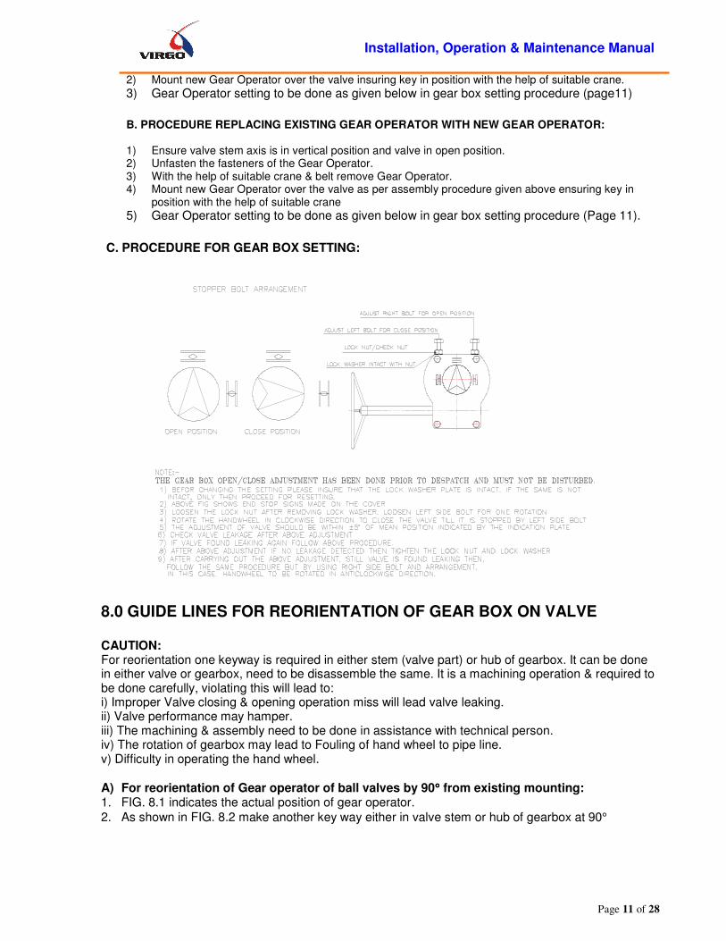
6.2 For gear operated valves, THE GEAR OPERATOR OPEN / CLOSE ADJUSTMENT HAS BEEN DONE PRIOR TO SHIPMENT AND MUST NOT BE CHANGED. Rotation of hand wheel in the clockwise direction closes the valve and counter clockwise rotation opens it. (Looking from hand wheel end) The details of gear operator are shown in the fig.

Installation, Operation & Maintenance Manual
Page 9 of 28
6.1. The internal details/construction of gear operator may vary as per manufacturer’s standard
6.3 Ball valve always closes in a clockwise direction. Valve should always be rotated through 90º to the fully opened or fully closed position.
6.4 Valve should be opened and closed slowly to avoid hammering effect on the valve and pipeline.
6.5 Once the flushing is complete, valve should be operated 3-4 times and then kept in the fully open position.
6.6 If the valve is not operating to fully open or fully closed position, and/or leaking, do not apply excessive force to operate the valve. This can damage the seats or stem.
• Apply gradual force on the handwheel of the gear operator and do not give impacts.
• Do not apply extra leverage (using pipe / bar), when the end stops of the gear operator are reached.
Fig 6.1 Gearbox drive arrangement
6.7 Lubrication of Worm Gear operator -
a. Worm gear operators are packed with grease. Normally the grease is suitable for - 20oC (-40F) to 80oC (1760F). For other applications, consult the nearest branch office / factory.
b. Grease should be changed as following: If operated frequently, after approx. 3 years. If operated rarely, after approx. 5 years.
c. Recommended Greases-
• Servogem EP2 (Extreme Pressure),
• Mobilux EP3,
• Valvoline EP3,
• Castrol EP3.
7.0 GUIDE LINES FOR ASSEMBLY AND DISASSEMBLY OF GEAR BOX ON VALVE:
Installation, Operation & Maintenance Manual
Page 10 of 28
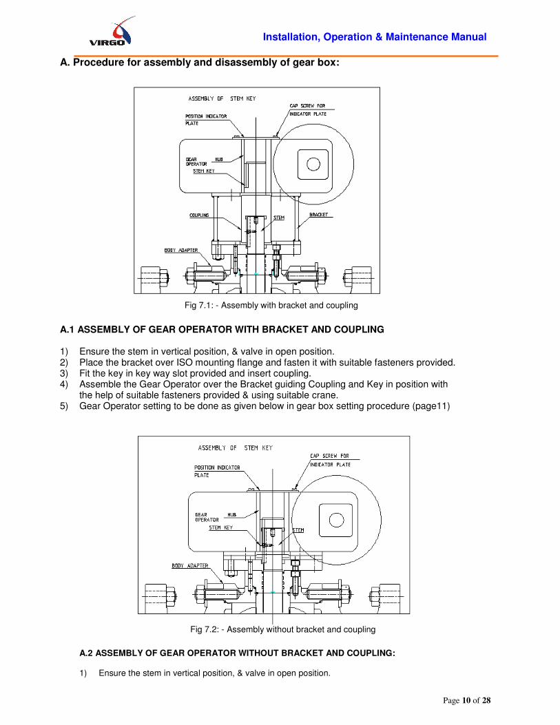
A. Procedure for assembly and disassembly of gear box:
Fig 7.1: - Assembly with bracket and coupling
A.1 ASSEMBLY OF GEAR OPERATOR WITH BRACKET AND COUPLING 1) Ensure the stem in vertical position, & valve in open position. 2) Place the bracket over ISO mounting flange and fasten it with suitable fasteners provided. 3) Fit the key in key way slot provided and insert coupling. 4) Assemble the Gear Operator over the Bracket guiding Coupling and Key in position with
the help of suitable fasteners provided & using suitable crane. 5) Gear Operator setting to be done as given below in gear box setting procedure (page11)
Fig 7.2: - Assembly without bracket and coupling A.2 ASSEMBLY OF GEAR OPERATOR WITHOUT BRACKET AND COUPLING: 1) Ensure the stem in vertical position, & valve in open position.
Installation, Operation & Maintenance Manual
Page 11 of 28
2) Mount new Gear Operator over the valve insuring key in position with the help of suitable crane.
3) Gear Operator setting to be done as given below in gear box setting procedure (page11)
B. PROCEDURE REPLACING EXISTING GEAR OPERATOR WITH NEW GEAR OPERATOR: 1) Ensure valve stem axis is in vertical position and valve in open position. 2) Unfasten the fasteners of the Gear Operator. 3) With the help of suitable crane & belt remove Gear Operator. 4) Mount new Gear Operator over the valve as per assembly procedure given above ensuring key in
position with the help of suitable crane
5) Gear Operator setting to be done as given below in gear box setting procedure (Page 11).
C. PROCEDURE FOR GEAR BOX SETTING:
8.0 GUIDE LINES FOR REORIENTATION OF GEAR BOX ON VALVE
CAUTION: For reorientation one keyway is required in either stem (valve part) or hub of gearbox. It can be done in either valve or gearbox, need to be disassemble the same. It is a machining operation & required to be done carefully, violating this will lead to: i) Improper Valve closing & opening operation miss will lead valve leaking. ii) Valve performance may hamper. iii) The machining & assembly need to be done in assistance with technical person. iv) The rotation of gearbox may lead to Fouling of hand wheel to pipe line. v) Difficulty in operating the hand wheel.
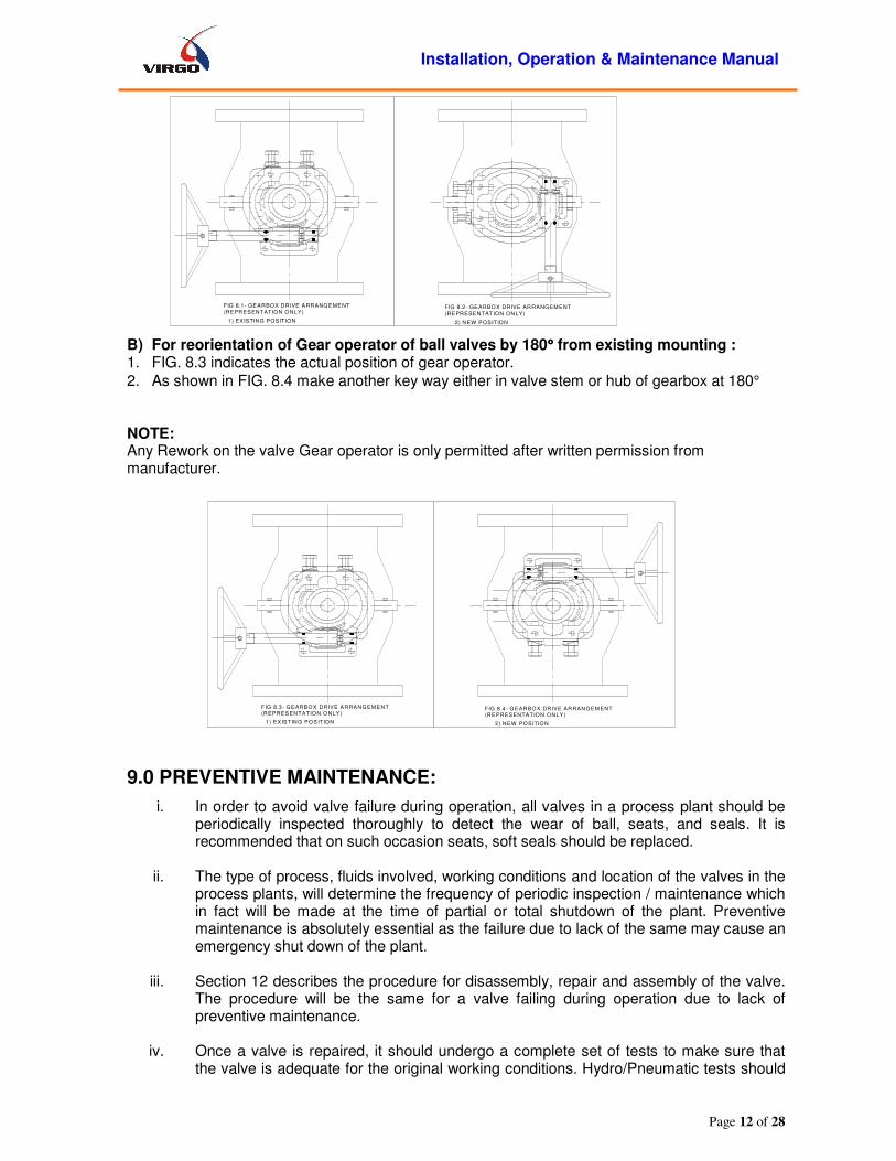
A) For reorientation of Gear operator of ball valves by 90°°°° from existing mounting: 1. FIG. 8.1 indicates the actual position of gear operator.
2. As shown in FIG. 8.2 make another key way either in valve stem or hub of gearbox at 90°
Installation, Operation & Maintenance Manual
Page 12 of 28
B) For reorientation of Gear operator of ball valves by 180°°°° from existing mounting : 1. FIG. 8.3 indicates the actual position of gear operator.
2. As shown in FIG. 8.4 make another key way either in valve stem or hub of gearbox at 180°
NOTE: Any Rework on the valve Gear operator is only permitted after written permission from manufacturer.
9.0 PREVENTIVE MAINTENANCE:
i. In order to avoid valve failure during operation, all valves in a process plant should be periodically inspected thoroughly to detect the wear of ball, seats, and seals. It is recommended that on such occasion seats, soft seals should be replaced.
ii. The type of process, fluids involved, working conditions and location of the valves in the
process plants, will determine the frequency of periodic inspection / maintenance which in fact will be made at the time of partial or total shutdown of the plant. Preventive maintenance is absolutely essential as the failure due to lack of the same may cause an emergency shut down of the plant.
iii. Section 12 describes the procedure for disassembly, repair and assembly of the valve.
The procedure will be the same for a valve failing during operation due to lack of preventive maintenance.
iv. Once a valve is repaired, it should undergo a complete set of tests to make sure that
the valve is adequate for the original working conditions. Hydro/Pneumatic tests should
1) EXISTING POSITION 2) NEW POSITION
FIG 8.1- GEARBOX DRIVE ARRANGEMENT(REPRESENTATION ONLY)
FIG 8.2- GEARBOX DRIVE ARRANGEMENT
(REPRESENTATION ONLY)
1) EXISTING PO SITION 2) NEW PO SITIO N
FIG 8.3- G EARBO X DRIVE ARRANG EM ENT
(REPRESENTATIO N O NLY)FIG 8.4- G EARBO X DRIVE ARRANGEM ENT(REPRESENTATIO N O NLY)
Installation, Operation & Maintenance Manual
Page 13 of 28
be carried out as per the specifications relevant to the valve (Refer General Arrangement Drawing).
9.1 Emergency Sealant Injection System in Trunnion Ball Valves:
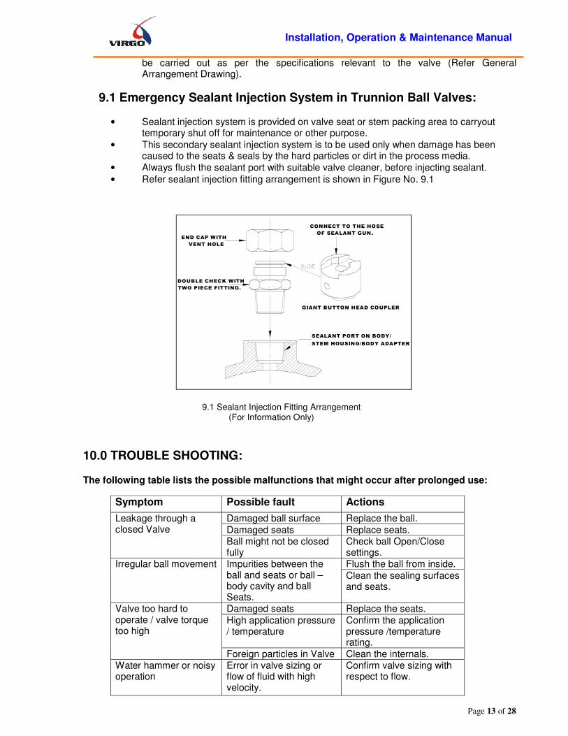
• Sealant injection system is provided on valve seat or stem packing area to carryout temporary shut off for maintenance or other purpose.
• This secondary sealant injection system is to be used only when damage has been caused to the seats & seals by the hard particles or dirt in the process media.
• Always flush the sealant port with suitable valve cleaner, before injecting sealant.
• Refer sealant injection fitting arrangement is shown in Figure No. 9.1
CONNECT TO THE HOSE
OF SEALANT GUN.END CAP WITH
VENT HOLE
DOUBLE CHECK WITH
TWO PIECE FITTING.
GIANT BUTTON HEAD COUPLER
SEALANT PORT ON BODY/
STEM HOUSING/BODY ADAPTER
9.1 Sealant Injection Fitting Arrangement (For Information Only)
10.0 TROUBLE SHOOTING:
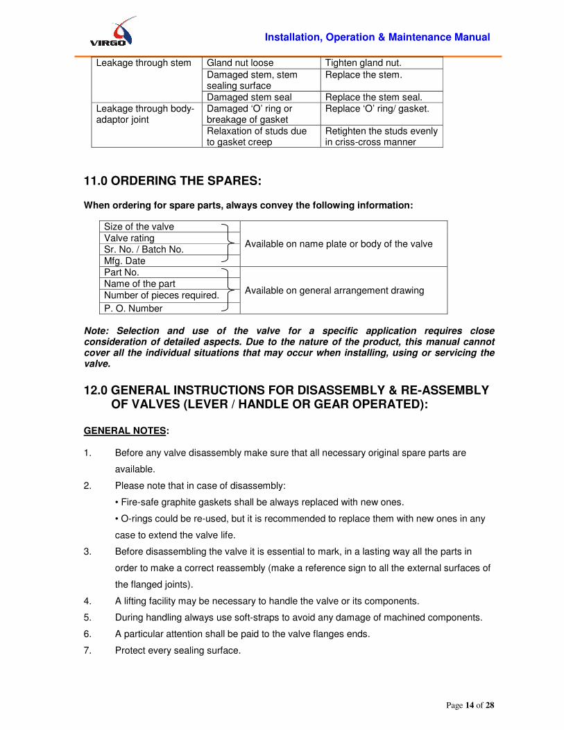
The following table lists the possible malfunctions that might occur after prolonged use:
Symptom Possible fault Actions
Leakage through a closed Valve
Damaged ball surface Replace the ball.
Damaged seats Replace seats. Ball might not be closed fully
Check ball Open/Close settings.
Irregular ball movement Impurities between the ball and seats or ball – body cavity and ball Seats.
Flush the ball from inside.
Clean the sealing surfaces and seats.
Valve too hard to operate / valve torque too high
Damaged seats Replace the seats.
High application pressure / temperature
Confirm the application pressure /temperature rating.
Foreign particles in Valve Clean the internals. Water hammer or noisy operation
Error in valve sizing or flow of fluid with high velocity.
Confirm valve sizing with respect to flow.
Installation, Operation & Maintenance Manual
Page 14 of 28
Leakage through stem Gland nut loose Tighten gland nut.
Damaged stem, stem sealing surface
Replace the stem.
Damaged stem seal Replace the stem seal. Leakage through body- adaptor joint
Damaged ‘O’ ring or breakage of gasket
Replace ‘O’ ring/ gasket.
Relaxation of studs due to gasket creep
Retighten the studs evenly in criss-cross manner
11.0 ORDERING THE SPARES:
When ordering for spare parts, always convey the following information:
Size of the valve
Available on name plate or body of the valve Valve rating Sr. No. / Batch No.
Mfg. Date Part No.
Available on general arrangement drawing Name of the part
Number of pieces required.
P. O. Number
Note: Selection and use of the valve for a specific application requires close consideration of detailed aspects. Due to the nature of the product, this manual cannot cover all the individual situations that may occur when installing, using or servicing the valve.
12.0 GENERAL INSTRUCTIONS FOR DISASSEMBLY & RE-ASSEMBLY
OF VALVES (LEVER / HANDLE OR GEAR OPERATED):
GENERAL NOTES:
1. Before any valve disassembly make sure that all necessary original spare parts are
available.
2. Please note that in case of disassembly:
• Fire-safe graphite gaskets shall be always replaced with new ones.
• O-rings could be re-used, but it is recommended to replace them with new ones in any
case to extend the valve life.
3. Before disassembling the valve it is essential to mark, in a lasting way all the parts in
order to make a correct reassembly (make a reference sign to all the external surfaces of
the flanged joints).
4. A lifting facility may be necessary to handle the valve or its components.
5. During handling always use soft-straps to avoid any damage of machined components.
6. A particular attention shall be paid to the valve flanges ends.
7. Protect every sealing surface.

Installation, Operation & Maintenance Manual
Page 15 of 28
8. Exploded view drawing shows the standard O-ring configuration but can be considered
as reference for lip-seal configuration too. To remove an actuator from the valve, refer to
specific actuator instructions.
9. After having disassembled a valve it is recommended to replace all the O-rings / Lip-seals
and the gaskets.
10. O-Rings require a certain tension to be inserted in their shoulders, be careful not to cause
cutting during re-assembling (Apply light grease compatible with working fluid).
12. I) TRUNNION MOUNTED BALL VALVES -
Pipeline and valve must be depressurized by shutting off the valves & the bleed line. Then cycling the valve once & leaving it half open to relieve the pressure from the body cavity.
12. I.A. Disassembly – Trunnion Mounted Ball Valves (Trunnion ball valve):
1. Valve shall be positioned vertically by resting body side flanges on clean ground surface
(preferably covered with rubber sheet). Ensuring no damage to the bottom/ end face/threads
as applicable)
2. Loosen safely the vent/drain plug (37) to relieve any residual pressure from the body cavity.
Rotate the ball (03) to fully open position.
3. Remove the locking screw (38) lift the handle (39) off the stem (04). Be careful not to damage
the stem key (30). (Remove the operator handle, lever or gearbox as applicable)
4. Open the body adapter joint by loosening the nuts in criss-cross pattern.
Always tighten / loosen the bolts in criss-cross pattern
5. Remove body adapter (02) use puller holes provided on body adapter for easy removing.
6. Remove the ‘O’-ring (body adapter) (07) & gaskets (body) (08) from the body adapter.
7. Remove seat (05), seat springs (28).
8. Remove Seat ‘O’-ring (06) from the seat.
9. Remove the ISOPAD (20) & stem housing (09) by loosening cap screws. Remove dowel pins.
10. Pull the stem (04). Loosen the cap screws of trunnion (25) and remove trunnion (22).
11. Remove the ball (03) from the body & the seats (05) from body & body adapter.
12. All the components should be stored in a clean place.
13. Remove the antistatic spring (27), the thrust washer (19) (trunnion & stem), the gasket
(trunnion) (23) & the ‘O’-ring (trunnion)(24).

Installation, Operation & Maintenance Manual
Page 16 of 28
14. Remove bush bearing (10) from ball & stem housing (10).
15. Where applicable, the sealant injection fittings [(stem) & (seat)] & drain/vent plugs (37) may be
removed for cleaning.
12. I.B. Re-assembly – Trunnion Mounted Ball Valves (Trunnion ball valve):
� Before reassembly, inspect the valve for any damage on Body-Adapter & all internals. � Wipe all the metal part with a petroleum solvent, using a soft cloth. � Ensure cleaning of valve. � Damaged internals to be replaced by genuine & with recommended parts only. � Before assembling the flanged joints check the reference sign applied before disassembly.
1. Body (02) shall be positioned vertically by resting body side flanges on clean ground
surface (preferably covered with rubber sheet).
2. Apply suitable industrial grease to bolting to prevent corrosion.
3. Put the respective o-rings & gaskets in to body (01), body adapter (02), seat (05), stem
housing (09), and trunnion (22).
4. Tighten the studs (17) to body.
5. Place the springs (28) into the seat (05) & insert seat (05) into the body recess (02)
6. Insert the bearing (10) in the ball (03) on trunnion side recess.
7. Lift the ball (03) & lower it into the body (01) so that ball bore is perpendicular to body bore.
8. Place thrust washer (26) in ball trunnion recess. Locate the trunnion (22) with bearing into the
ball recess. Then tighten it with the cap screws (25) or hex bolts.
9. Insert stem (04) along with thrust washer (19) and align its key slot parallel to the body bore.
10. For lever-operated valve align stem A/F parallel with the body bore.
11. Insert the bush bearings (10) in to the stem housing (09).
12. Insert dowel pin (15) in the dowel hole provided on body.
13. Insert stem housing (09); locate its dowel hole on body.
14. Tighten stem housing (09) with cap screws (16).
15. Insert ISOPAD (20); locate its dowel hole on stem housing (09).
16. Tighten the ISOPAD (20) to the stem housing with cap screws (20).
17. Put another seat (05) with springs (28) on the ball followed body adapter (02).
18. Tighten the body nuts (18) in a crisscross pattern. (Refer Table A for recommended tightening
torque)
19. Fit the stem key (30) in stem keyway.
20. Lift the valve & place it so that the direction of the flow axis is horizontal.
21. Put the operating member i.e. lever/ handle or G.O. in position into body & tighten them.
22. Ensure proper locking of stem with lock nut, washer or mounting plate as applicable.
23. Ensure open and close smooth operation of valve.
24. For lever operated valves, place the hand coupler (not shown) with lock & stop plate (not
shown) on the stem & tighten the hex bolt/grub screw.
25. For gear operated valves, place the coupling on the stem, place the bracket on the stem
housing, fit the studs & tighten the nuts. Place the gear operator on the coupling & the bracket,
fit the studs & tighten the nuts.
26. Where applicable, fit sealant injection fittings [(stem) & (seat)] & the drain/vent plugs.

Installation, Operation & Maintenance Manual
Page 17 of 28
27. Rotate the ball slowly back & forth to a full quarter turn. This will allow the seat to assume its
permanent position & shape against ball & body. A fast turning motion may damage the seat
before it has a chance to form a proper seal. Note: For three-piece design ball valves there are two-body adapter & one body. In this case the assembly procedure remains the same as explained above for two-piece ball valve except that the body adapter side flange is to be positioned on clean ground side as
mentioned in clause 12.I.A-1.
12. I.C. Exploded view: Two Piece & Three Piece Design - Trunnion Mounted Ball Valves - (Trunnion ball valve):
TWO PIECE BALL VALVE
THREE PIECE BALL VALVE

Installation, Operation & Maintenance Manual
Page 18 of 28
Note: Always use the genuine spare parts to make sure that the valve functions as intended.
12. I.D. Disassembly – Trunnion Mounted Ball Valves (Trunnion plate ball valve):
1. Valve shall be positioned vertically by resting body side flanges on clean ground
surface (preferably covered with rubber sheet). Ensuring no damage to the bottom/
end face/threads as applicable)
2. Loosen safely the vent/drain plug (37) to relieve any residual pressure from the
body cavity.
3. Rotate the ball (03) to fully open position.
4. Remove the locking screw (38) lift the wrench (39) off the stem (04)(Not shown). Be
careful not to damage the stem key (30). (Remove the operator handle, lever or
gearbox as applicable).
5. Open the body adapter joint by loosening the nuts in criss-cross pattern.
6. Remove body adapter (02). Use puller holes provided on body adapter for easy
removing.
7. Remove the ‘O’-ring (body adapter) (07) & gaskets (body) (08) from the body
adapter.
8. Remove seat (05), seat springs (28).
9. Remove Seat ‘O’-ring (06) from the seat.
10. Remove the ISO PAD (20) & stem housing (09) by loosening cap screws. Remove
dowel pins.
11. Remove the stem (04).
12. Remove the ball (03) & trunnion plate (22) assembly from the body & then seat (05)
from body & body adapter.
13. Remove Seat ‘O’-ring (06) from the seat.
14. Remove trunnion plates (22) from ball and trunnion plate assembly, and then remove
the trunnion plate bush bearings (10).
15. Remove the dowels (23) in the trunnion plate.
16. All the components should be stored in a clean place.
17. Remove the thrust washers (trunnion plate) (26).
18. Remove all stem housing & trunnion seals.
19. Where applicable the sealant injection fittings [(stem) & (seat)] & drain/vent plugs
may be removed for cleaning.

Installation, Operation & Maintenance Manual
Page 19 of 28
12. I.E. Reassembly – Trunnion Mounted Ball Valves (Trunnion plate ball valve):
� Before reassembly, inspect the valve for any damage on Body-Adapter & all internals.
� Ensure cleaning of valve.
� Damaged internals to be replaced by genuine & with recommended parts only.
� Before assembling the flanged joints check the reference sign applied before disassembly.
1. Body (02) shall be positioned vertically by resting body side flanges on clean ground
surface (preferably covered with rubber sheet).
2. Apply suitable industrial grease to bolting to prevent corrosion.
3. Put the respective o-rings & gaskets in to body (01), body adapter (02), seat (05), stem
housing (09), and trunnion (22).
4. Tighten the studs (17) to body.
5. Place the springs (28) into the seat (05) & insert seat (05) into the body recess (02)
6. Insert the dowel pins (23) in the trunnion plate.
7. Press bush bearing (26) into the trunnion plate recess then insert the thrust washer on
the ball.
8. Insert the trunnion plates (22) on the ball.
9. Lift the ball (03) & trunnion plate (22) assembly & lower it into the body so that ball bore is
perpendicular to body bore.
10. Match the dowel pin (23) to the dowel hole on body or body adapter (in case of 3-pc
trunnion plate ball valve.)
11. Insert stem along with thrust washer and align its key slot parallel to the body bore.
12. For lever-operated valve align stem A/F parallel with the body bore.
13. Insert dowel pin (15) in the dowel hole provided on body.
14. Insert stem housing (09); locate its dowel hole on body.
15. Tighten stem housing (09) with cap screws (16).
16. Insert ISOPAD (20); locate its dowel hole on stem housing (09).
17. Tighten the ISOPAD (20) to the stem housing with cap screws (20).
18. Put another seat (05) with springs (28) on the ball followed body adapter (02).
19. Tighten the body nuts (18) in a crisscross pattern. (Refer Table A for recommended
tightening torque)
20. Fit the stem key (30) in stem keyway.
21. Fit the stem key in stem key way.
22. Put another seat (05) with springs (28) on the ball followed by body adapter (02).
23. Tighten the nuts (18) in a crisscross pattern.
24. Lift the valve & place it so that the direction of the flow axis is horizontal.
25. Put the operating member i.e. lever/ handle or G. O. in position into body & tighten them.

Installation, Operation & Maintenance Manual
Page 20 of 28
26. Ensure proper locking of stem with lock nut, washer or mounting plate (not shown)
as applicable.
27. Ensure smooth open and close operation of valve.
28. For lever operated valves, place the hand coupler with lock & stop plate on the stem
& tighten the hex bolt / grub screw.
29. For gear operated valves, place the coupling on the stem, place the bracket on the
stem housing, fit the studs & tighten the nuts. Place the gear operator on the
coupling & the bracket, fit the studs & tighten the nuts.
30. Where applicable, fit sealant injection fittings [(stem) & (seat)] & the drain/vent plugs
(37).
31. Rotate the ball slowly back & forth to a full quarter turn. This will allow the seat to
assume its permanent position & shape against ball & body. A fast turning motion
may damage the seat before it has a chance to form a proper seal.
Note: For three-piece design ball valves there are two-body adapter & one body. In
this case the assembly procedure remains the same as explained above for two-piece ball valve except that the body adapter side flange is to be
positioned on clean ground side as mentioned in clause 12.I.E.1

Installation, Operation & Maintenance Manual
Page 21 of 28
12. I.F. Exploded view: Three Piece & Two piece Design – Trunnion Ball Valve –
(Trunnion plate Ball valve):
Note: Always use the genuine spare parts to make sure that the valve functions as intended.
Installation, Operation & Maintenance Manual
Page 22 of 28
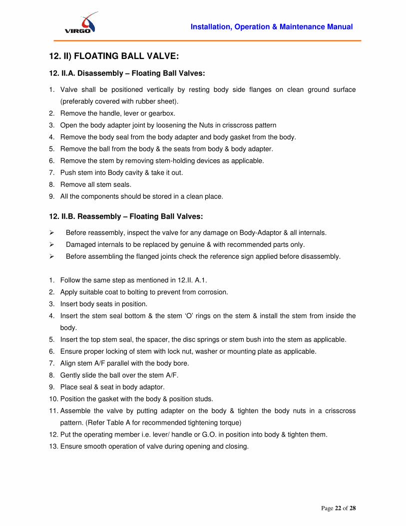
12. II) FLOATING BALL VALVE:
12. II.A. Disassembly – Floating Ball Valves:
1. Valve shall be positioned vertically by resting body side flanges on clean ground surface
(preferably covered with rubber sheet).
2. Remove the handle, lever or gearbox.
3. Open the body adapter joint by loosening the Nuts in crisscross pattern
4. Remove the body seal from the body adapter and body gasket from the body.
5. Remove the ball from the body & the seats from body & body adapter.
6. Remove the stem by removing stem-holding devices as applicable.
7. Push stem into Body cavity & take it out.
8. Remove all stem seals.
9. All the components should be stored in a clean place.
12. II.B. Reassembly – Floating Ball Valves: � Before reassembly, inspect the valve for any damage on Body-Adaptor & all internals.
� Damaged internals to be replaced by genuine & with recommended parts only.
� Before assembling the flanged joints check the reference sign applied before disassembly.
1. Follow the same step as mentioned in 12.II. A.1.
2. Apply suitable coat to bolting to prevent from corrosion.
3. Insert body seats in position.
4. Insert the stem seal bottom & the stem ‘O’ rings on the stem & install the stem from inside the
body.
5. Insert the top stem seal, the spacer, the disc springs or stem bush into the stem as applicable.
6. Ensure proper locking of stem with lock nut, washer or mounting plate as applicable.
7. Align stem A/F parallel with the body bore.
8. Gently slide the ball over the stem A/F.
9. Place seal & seat in body adaptor.
10. Position the gasket with the body & position studs.
11. Assemble the valve by putting adapter on the body & tighten the body nuts in a crisscross
pattern. (Refer Table A for recommended tightening torque)
12. Put the operating member i.e. lever/ handle or G.O. in position into body & tighten them.
13. Ensure smooth operation of valve during opening and closing.
Installation, Operation & Maintenance Manual
Page 23 of 28
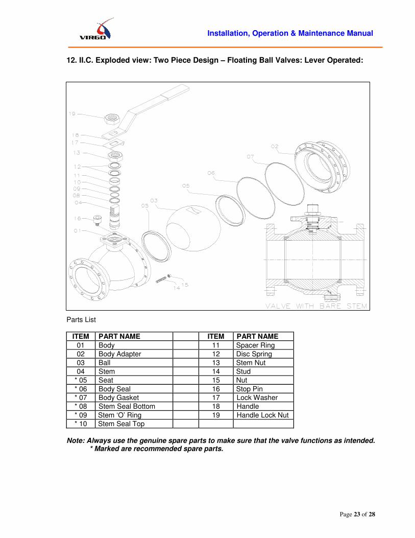
12. II.C. Exploded view: Two Piece Design – Floating Ball Valves: Lever Operated:
Parts List
ITEM PART NAME ITEM PART NAME
01 Body 11 Spacer Ring
02 Body Adapter 12 Disc Spring
03 Ball 13 Stem Nut
04 Stem 14 Stud
* 05 Seat 15 Nut
* 06 Body Seal 16 Stop Pin
* 07 Body Gasket 17 Lock Washer
* 08 Stem Seal Bottom 18 Handle
* 09 Stem ‘O’ Ring 19 Handle Lock Nut
* 10 Stem Seal Top
Note: Always use the genuine spare parts to make sure that the valve functions as intended.
* Marked are recommended spare parts.
Installation, Operation & Maintenance Manual
Page 24 of 28
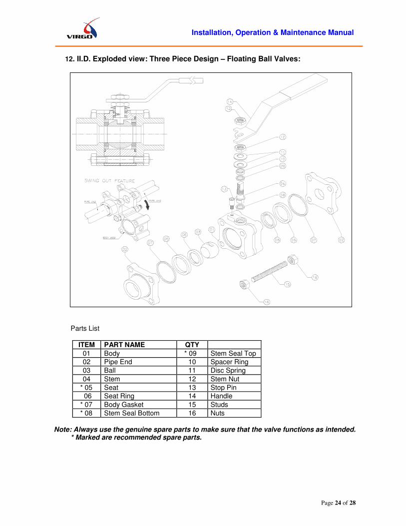
12. II.D. Exploded view: Three Piece Design – Floating Ball Valves:
Parts List
ITEM PART NAME QTY
01 Body * 09 Stem Seal Top
02 Pipe End 10 Spacer Ring
03 Ball 11 Disc Spring
04 Stem 12 Stem Nut
* 05 Seat 13 Stop Pin
06 Seat Ring 14 Handle
* 07 Body Gasket 15 Studs
* 08 Stem Seal Bottom 16 Nuts
Note: Always use the genuine spare parts to make sure that the valve functions as intended.
* Marked are recommended spare parts.

Installation, Operation & Maintenance Manual
Page 25 of 28
12. II.E. Exploded view: Two Piece Design – Floating Ball Valves - Gear Operated:
Parts List
ITEM PART NAME
01 Body 10 Stem Bush
02 Body Adapter 11 Body Stud
03 Ball 12 Body Nut
04 Stem 13 Stem Key
* 05 Seat 14 ISOPAD
* 06 Body ‘O’ Ring 15 Cap screw for ISOPAD
* 07 Body Gasket 16 Gearbox
* 08 Stem Seal Bottom 17 Stud for Gear box
* 09 Stem ‘O’ Ring 18 Nut for gearbox.
Note: Always use the genuine spare parts to make sure that the valve functions as intended. * Marked are recommended spare parts.

Installation, Operation & Maintenance Manual
Page 26 of 28
TABLE: A - RCOMMENDED TIGHTENING TORQUES FOR BOLTING, N-m (For Information Only)
FOR METRIC SERIES TORQUE (N-m) FOR INCH SERIES. TORQUE (N-m)
Thread Size (Metric)
Pitch LOW RES.*
HIGH RES** Thread Size
(INCH) TPI LOW RES.* HIGH RES**
M10 1.5 30 40 1/2 13 61 80
M12 1.75 52 69 5/8 11 118 155
M14 2 83 108 3/4 10 206 270
M16 2 126 165 7/8 9 328 429
M18 2.5 174 228 1 8 488 639
M20 2.5 243 318 1-1/8 8 706 925
M22 2.5 327 428 1-1/4 8 981 1285
M24 3 415 544 1-3/8 8 1320 1727
M27 3 601 787 1-1/2 8 1727 2261
M30 3.5 814 1066 1-5/8 8 2211 2894
M33 3.5 1097 1436 1-3/4 8 2777 3636
M36 4 1410 1845 1-7/8 8 3433 4493
M39 4 1810 2370 2 8 4183 5476
M42 4.5 2241 2934 2-1/4 8 5997 7851
M45 4.5 2780 3639 2-1/2 8 8271 10828
M48 5 3348 4383 2-3/4 8 11117 14591
M52 5 4298 5626 3 8 14481 19007
M56 5.5 5343 6995 3-1/4 8 18462 24232
M60 5.5 6624 8671 3-1/2 8 23114 30336
Note: ensure that all the nuts/bolts are tightened to the torque values as specified in this Table.
*Low resistance Bolting: Material Grade e.g. L7M, B7M
**High resistance Bolting: Material Grade B7, L7
Use above value for normally lubricated surface ( UNCOATED ) only machining oil
For coated bolts multiply for reduction factor: 0.65- PTFE COATED
TABLE: B - RCOMMENDED TIGHTENING TORQUES FOR NPT THREADS
Plug size Thread per Inch Approx. Torque
Ft-lbs N-m
3/8 NPT 18 45 61
1/2 NPT 14 50 68
3/4 NPT 14 55 75
1 NPT 11-1/2 65 88

Installation, Operation & Maintenance Manual
Page 27 of 28
Customer
Project
Consultant
P. O. No. And Date
Work Order No.
Date of Last Dispatch
Date of Commissioning
Warranty: “Our liability in respect of any defect in or failure of the goods supplied or for any loss, injury or damage
attributable thereto is limited to making goods by replacement or repair defects which under proper use
appear therein and arise solely from faulty materials and workmanship within a period of 18 calendar
months after the original goods shall have been first dispatched or 12 calendar months from the date of
commissioning, whichever is earlier provided that such defective parts are returned free to our works
for examination. The undertaking shall exclude any and every other obligation.”
Virgo does not assume responsibilities for any liabilities/damages arriving out of wrong application of its valves, or imprudent operations carried out by inexperienced operators, or which does not comply with this manual, or instructions provided by Virgo. The valves shall be appropriately used for the purpose they are built, or applications they are supplied. Use of standard valves for special applications is not recommended unless it has been communicated and agreed to by Virgo. Valves shall be operated and maintained strictly in accordance with the procedures. Operation or maintenance outside these procedures constitutes abuse of the product and voids all warranty and claims.
13.0 ADDRESSES FOR CORRESPONDENCE:
In case of service / repair, please contact our nearest Branch Office / Factory.
Head Office & Works : VIRGO ENGINEERS LIMITED 277, Raisoni Industrial Park, Phase II, Hinjewadi, Maan (Mulshi), Pune – 411 057, INDIA. Phone: +91-20-66744000.
Fax: +91-20-66744021. E-mail : [email protected] Website: www.virgoengineers.com
Installation, Operation & Maintenance Manual
Page 28 of 28
13. I ADDRESSES FOR CORRESPONDENCE: Branch offices India and overseas:
Mumbai Unit No. 103, First Floor, A - Wing, Building No. 1, Kailash Industrial Complex, Behind Godrej Colony, Off. L.B.S.Marg, Parksite, Vikhroli (E ) Mumbai - 400 079 Phone : 022 40100700 Fax : 022 40110701 E-mail : [email protected]
Kolkata 2-B, Haralal Das Street 2nd Floor, Entally Kolkata 700 014 Tel : (033) 22272269 / 22272533 Fax : (033) 22272279 E-mail : [email protected]
Baroda 14, Guruprasad Society, Behind Akota Stadium, Baroda-390 015. INDIA Phone :+91-265-2342837, 2355133, 2341053 Fax : +91-265- 2314449 E-mail : [email protected]
Chennai No. 59, Ground Floor, Teacher’s Colony, Karma Avenue, Ayer, Chennai-600 020. INDIA Phone : +91-44- 24404119 Fax : +91-44-24410664 E-mail : [email protected]
Delhi 7/39, 2nd Floor, 1 B, Vikram Vihar, Lajapat Nagar, New Delhi – 110 024. INDIA Phone : +91-11- 51729161/2/3/4 Fax : +91-11- 51729164 E-mail : [email protected]
MALAYSIA Virgo Valves and Controls Ltd. Suite 1904, 19th Floor, Kenanga International Jalan Sultan Ismail,50250 Kuala Lumpur, Malaysia Ph : +60 3 21618260 Fax : +60 3 21666489 E-mail : [email protected]
VIRGO ENGINEERS INC. (Sales & Distribution Office) USA 10225 MULA ROAD, SUITE 130, STAFFORD, TEXAS 77477, U.S.A. TEL : +1 281 933 3100 FAX : +1 281 933 3110 E-mail : [email protected]
Virgo Valves & Controls Limited (Warehouse and Valve Automation Center) Unit - Fzs1 AH07,Jebel Ali Free Zone (South), P.O. Box – 18478, Dubai-UAE Phone : +971-4-8860980 Fax : +971-4-8860981
VIRGO EUROPE S.P.A., ITALY VIA DELLE ORCHIDEE N.7 20020 VANZAGHELLO MI ITALY. TEL : +39.0331.308.211 FAX : +39.0331.306299 E-mail : [email protected]
Document Path: P:\USERS\SPECS\ISO\IOM\IOM01R11.doc Rev No.: 11 Published On: 12/03/2011