installation operation maintenance - · pdf fileunit inspection ... check all items against...
TRANSCRIPT

© 2003 American Standard Inc. All rights reserved. CGWF-SVX01A-EN
InstallationOperationMaintenance
Scroll Liquid Chillers
Models CGWF/CCAF20-60 Tons
January 2004
2 CGWF-SVX01A-EN
Important
Environmental Concerns!
Scientific research has shown that certain man-made chemicals can
affect the earth’s naturally occurring stratospheric ozone layer when
released to the atmosphere. In particular, several of the identified
chemicals that may affect the ozone layer are refrigerants that contain
Chlorine, Fluorine and Carbon (CFCs) and those containing Hydrogen,
Chlorine, Fluorine and Carbon (HCFCs). Not all refrigerants containing
these compounds have the same potential impact to the environment.
Trane advocates the responsible handling of all refrigerants—including
industry replacements for CFCs such as HCFCs and HFCs.
Responsible Refrigerant Practices!
Trane believes that responsible refrigerant practices are important to the
environment, our customers, and the air conditioning industry. All
technicians who handle refrigerants must be certified. The Federal Clean
Air Act (Section 608) sets forth the requirements for handling,
reclaiming, recovering and recycling of certain refrigerants and the
equipment that is used in these service procedures. In addition, some
states or municipalities may have additional requirements that must
also be adhered to for responsible management of refrigerants. Know
the applicable laws and follow them.
� WARNING
Contains Refrigerant!
System contains oil and refrigerant under high pressure. Recover
refrigerant to relieve pressure before opening the system. See unit
nameplate for refrigerant type. Do not use non-approved refrigerants,
refrigerant substitutes, or refrigerant additives.
Failure to follow proper procedures or the use of non-approved
refrigerants, refrigerant substitutes, or refrigerant additives could result
in death or serious injury or equipment damage.
NOTICE: Warnings and Cautions appear at appropriate sections through-out this literature. Read these carefully.
� WARNING: Indicates a potentially hazardous situation which, if not avoided, could result in death or serious injury.
� CAUTION: Indicates a potentially hazardous situation which, if not avoided, may result in minor or moderate injury. It may also be used to alert against unsafe practices.
CAUTION: Indicates a situation that may result in equipment or property-damage only accidents.

CGWF-SVX01A-EN 3
Table of ContentsGeneral Information........................................................................................... 7
Literature Change History..................................................................................... 7Unit Identification ................................................................................................. 7Nameplates .......................................................................................................... 7Unit Nameplates................................................................................................... 7Compressor Nameplate ....................................................................................... 7Evaporator Nameplate.......................................................................................... 7Condenser Nameplate.......................................................................................... 8Unit Inspection ..................................................................................................... 8Inspection Checklist ............................................................................................. 8Loose Parts Inventory .......................................................................................... 8Unit Description.................................................................................................... 8Unit Model Number.............................................................................................. 8Installation Overview.......................................................................................... 12
Installation Mechanical .................................................................................... 17
Unit Storage ....................................................................................................... 17Location Requirement ........................................................................................ 17Noise Consideration ........................................................................................... 17Foundation.......................................................................................................... 17Ventilation........................................................................................................... 17Drainage ............................................................................................................. 17Rigging ............................................................................................................... 17Lifting Procedure for 20-50 Ton CGWF 20-60 and Ton CCAF Units................... 18Lifting Procedure for 60 Ton Units ..................................................................... 20Alternate Moving Methods................................................................................. 21Access Restrictions............................................................................................ 21Recommended Clearances ................................................................................ 22Unit Isolation ...................................................................................................... 22Direct Mounting ................................................................................................. 22Neoprene Isolator Mounting .............................................................................. 22Neoprene Isolator Data ...................................................................................... 22Unit Leveling ...................................................................................................... 23Unit Piping .......................................................................................................... 29General Water Piping Recommendations .......................................................... 29Water System .................................................................................................... 29Water Flow Rates............................................................................................... 29Pressure Drop Measurement ............................................................................. 29Evaporator Water Piping..................................................................................... 32Evaporator Water Connections........................................................................... 32Evaporator Piping Components.......................................................................... 32Flow Sensing Devices ........................................................................................ 32Evaporator Drain. ................................................................................................ 33Condenser Water Piping .................................................................................... 33Condenser Water Connections. ......................................................................... 33Condenser Piping Components.......................................................................... 33Condenser Drains. .............................................................................................. 34Water Regulating Valve ...................................................................................... 35Water pressure Relief Valves ............................................................................. 37Low Temperature Operation .............................................................................. 37Pressure Relief Valve Venting ............................................................................ 38Refrigerant Piping (CCAF only) ........................................................................... 40

4 CGWF-SVX01A-EN
Table of Contents
Liquid Line Components and Connections......................................................... 40Liquid Line Sizing................................................................................................ 40Discharge (hot gas) Lines ................................................................................... 40Leak Test ............................................................................................................ 42System Evacuation ............................................................................................. 42Refrigerant Charging........................................................................................... 42
Installation Electrical ........................................................................................ 43
General Recommendations ................................................................................ 43Power Supply Wiring .......................................................................................... 43Unit Power Supply .............................................................................................. 43Equipment Grounds............................................................................................ 43Terminal Lugs, Circuit Breakers and Non-Fused Disconnect Switches.............. 43Scroll Compressor Electrical Phasing ................................................................. 47Correcting Improper Electrical Phase Sequence ................................................ 47Unit Voltage ........................................................................................................ 48Voltage Imbalance .............................................................................................. 48Control Power Supply ......................................................................................... 48Modules Connections for Interconnecting Wiring.............................................. 48Chilled Water Flow Switch ................................................................................. 49Chilled Water Pump Control ............................................................................... 49Condenser Water Loss of Flow Protection ........................................................ 49Condenser Water Pump Starter ......................................................................... 49Programmable Relays......................................................................................... 49External Auto/Stop.............................................................................................. 50Compressor Inhibit/ High Ambient Operation .................................................... 50Condenser Water Temperature Sensor Connections......................................... 50Chilled Water Rest.............................................................................................. 50External Chilled Water Setpoint Option.............................................................. 51Ice Machine Control Option................................................................................ 51Communications Interface options..................................................................... 51Optional Tracer Communications Interface ........................................................ 51LonTalk Communications Interface for Chillers (LCI-C) Option .......................... 52CCAF - Fan Control ............................................................................................. 54Outdoor Air Temperature Control ....................................................................... 54
Operating System ............................................................................................ 55
Controls Interface ............................................................................................. 57
CH530 Communications Overview .................................................................... 57Controls Interface ............................................................................................... 57DynaView ........................................................................................................... 57TechView............................................................................................................ 57DynaView Interface ............................................................................................ 58Key Functions ..................................................................................................... 58Radio Buttons ..................................................................................................... 58Spin Value Buttons ............................................................................................. 58Action Buttons.................................................................................................... 59File Folder Tabs .................................................................................................. 59Display Screens .................................................................................................. 59Basic Screen Format .......................................................................................... 59Keypad/Display Lockout Feature ........................................................................ 60
CGWF-SVX01A-EN 5
Table of ContentsMain Screens ..................................................................................................... 61Reports Screen................................................................................................... 65Settings Screen .................................................................................................. 67Diagnostics Screen............................................................................................. 69TechView Interface ............................................................................................ 69Software Download............................................................................................ 70Instructions for First Time TechView Users ....................................................... 70
Diagnostics ....................................................................................................... 73
Unit Start-up..................................................................................................... 77
Pre-Start Checklist .............................................................................................. 77Unit Power Up .................................................................................................. 79Checking Operating Conditions.......................................................................... 79System Superheat .............................................................................................. 80System Subcooling............................................................................................. 80
Unit Shutdown ................................................................................................. 81
Normal Unit Shutdown....................................................................................... 81Extended Shutdown Procedure ......................................................................... 81System Restart After Extended Shutdown ........................................................ 82
Unit Maintenance............................................................................................. 83
Periodic Maintenance......................................................................................... 83Weekly Maintenance.......................................................................................... 83Monthly Maintenance ........................................................................................ 83Annual Maintenance........................................................................................... 83Maintenance Procedures ................................................................................... 84Mechanical Cleaning .......................................................................................... 84Chemical Cleaning.............................................................................................. 84Cleaning the Evaporator (Chiller) ........................................................................ 84Water Treatment ................................................................................................ 85
Wiring Schematics ........................................................................................... 89
Schematics Page 1&2 ......................................................................................... 90Component Location ........................................................................................... 94Field Wiring Diagram ........................................................................................... 95Field Layout Diagram........................................................................................... 96

6 CGWF-SVX01A-EN
Table of Contents

CGWF-SVX01A-EN 7
General Information
Literature Change HistoryNew manual describes the installation, operation and maintenance of CGWF/CCAF Units.
Unit IdentificationWhen the unit arrives, compare all nameplate data with ordering, submittal, and shipping information. A typical unit nameplate is shown in Figure 1.
Nameplates
Unit NameplatesThe CGWF/CCAF unit nameplate is mounted on the control panel door. The Unit nameplate provides the following information:• Unit model number.
• Unit serial number.
• Identifies unit electrical requirements.
• Lists correct operation charge of R-22 and refrigerant oil.
• Lists unit test pressures and maximum operating pressures.
• Identifies installation, operation and maintenance literature.
• Lists the drawing numbers for the unit wiring diagrams.
Compressor NameplateThe nameplate for the Scroll compressor is mounted on the compressor housing near the motor terminal box.
Evaporator NameplateThe evaporator ASME nameplate is mounted on the top of the evaporator supply-end tube sheet. The word “nameplate” is applied to the insulation just above the nameplate. To view the evaporator nameplate, remove the tape over the area and spread the insulation.
Figure 1 Unit Nameplate
8 CGWF-SVX01A-EN
General Information
Condenser NameplateThe condenser ASME nameplate (30 and 60 ton condensers only) is mounted on the top of the condenser near the water outlet on 60 ton units and on the side of the condenser near the water outlet on 30 ton units.
Unit InspectionCarefully inspect chiller while still on shipping conveyance. If unit is damaged or has broken free from anchorage, require inspection by transportation inspectors. File damage claims with the carrier and notify a Trane sales representative. The manufacturer is not responsible for damage occurring during transit. Do not install a damaged unit without sales office approval.
Inspection ChecklistTo protect against loss due to damage incurred in transit, complete the following checklist upon receipt of the unit:• Inspect individual pieces of the shipment before accepting the unit. Check for
obvious damage to the unit or packing material.
• Check the unit for concealed damage before it is stored and as soon as possible after delivery. Concealed damage must be reported within 15 days.
• If concealed damage is discovered, stop unpacking the shipment. Do not remove damaged material from receiving location. Take photos of the damage, if possible. The owner must provide reasonable evidence that the damage did not occur after delivery.
• Notify the carrier’s terminal of damage immediately by phone and by mail. Request an immediate joint inspection of the damage by the carrier and the con-signee.
• Notify a Trane sales representative and arrange for repair. Do not repair the unit until damage is inspected by the carrier’s representative.
Loose Parts InventoryCheck all items against shipping list. Water vessel drain plugs, rigging and electrical diagrams, service literature and optional water temperature sensors are placed inside the UCP (unit control panel) for shipment before it is shrinkwrapped with waterproof plastic. When ordered, the optional neoprene isolators are secured in place on the shipping skid.
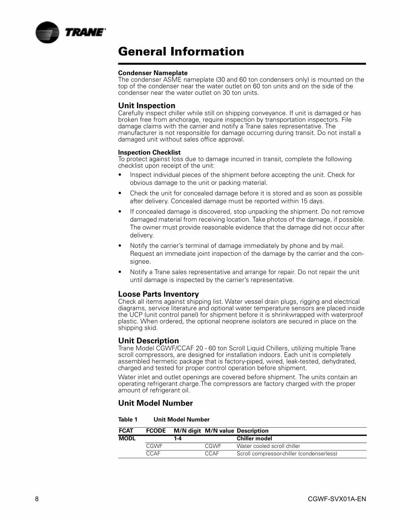
Unit DescriptionTrane Model CGWF/CCAF 20 - 60 ton Scroll Liquid Chillers, utilizing multiple Trane scroll compressors, are designed for installation indoors. Each unit is completely assembled hermetic package that is factory-piped, wired, leak-tested, dehydrated, charged and tested for proper control operation before shipment.Water inlet and outlet openings are covered before shipment. The units contain an operating refrigerant charge.The compressors are factory charged with the proper amount of refrigerant oil.
Unit Model Number
Table 1 Unit Model Number
FCAT FCODE M/N digit M/N value Description
MODL 1-4 Chiller model
CGWF CGWF Water cooled scroll chillerCCAF CCAF Scroll compressor-chiller (condenserless)

CGWF-SVX01A-EN 9
General Information
NTON 5-7 Unit nominal tonnage
20 020 20 nominal tons25 025 25 nominal tons30 030 30 nominal tons40 040 40 nominal tons50 050 50 nominal tons60 060 60 nominal tons
VOLT 8 Unit Voltage
DULA G 208-230/60/3 power supply380A D 380/60/3 power supply460A 4 460/60/3 power supply575A 5 575/60/3 power supply400B N 400/50/3 power supply
SHIPCYC 9 Ship cycle
MTO (C) Made to orderSTK (C) Packed stock (contact BU)
DSEQ 10-11 Design sequence
A0 A0 Factory/ABU assignedAGLT 12 Agency listing
NONE N No agency listingUL U C/UL listing
CODE 13 Pressure vessel code
ASME A ASME codeCAN C Canadian code
SPKG 14 Shipping Package
FLBT A Ship via Flat Bed TruckSHRK B Ship w/Shrink Wrap Bag and SkidSKID C Ship w/Skid
CDTE 15 Condenser temp range
NA 0 None - CCAF unitsSTD 1 Standard 60-90F [15.6-32.2C] entering water tempHIGH 4 High 90-130F [32.2-54.4C] entering water temp
CDTT 16 Condenser tube material
NA N None - CCAF unitsSTD C Std copper finned tubes
CDCO 17 Condenser water connections
NA N None - CCAF unitsLHWC L Left hand condenser connectionsRHWC R Right hand condenser connections
EVTL 18 Evap temp range
STD 1 Standard cooling 40-60F[4.4-15.6C]LOWA 2 Ice making 26-39F[-3.3-3.9C]LOWB 3 Low temp 10-25F[-12.2-(-3.9)C]ICE 4 Standard cooling/Ice making 20-60F[-6.7-15.6C]
PCON 19 Power line connection type
TB T Terminal blockDISC D Non-fused disconnect switch
EPRO 20 Short circuit rating
NONE 0 No short circuit ratingSCR 1 With short circuit rating
Table 1 Unit Model Number
FCAT FCODE M/N digit M/N value Description

10 CGWF-SVX01A-EN
General Information
CIOP 21 Control input options
NONE N No optionsREMS R Remote chilled water setpoint inputREMC C Remote compressor inhibit and/or icemaking inputREMB B Remote CWS and compressor inhibit/icemaking
inputCOOP 22 Control output options
NONE N No optionsPROG P Programmable relays for remote alarm, run, etc.
SENS 23 Auxiliary sensor options
NONE 0 NoneCDWT 1 Condenser water temp sensors (CGWF only)AMB 2 Outdoor temp sensor - CWR or Amb LockoutBOTH 3 Both condenser and outdoor temp sensor
COMM 24 Communication options
NONE 0 NoneCOM3 3 Tracer Summit interfaceLCIC 5 LonTalk LCI-C interface
HGBP 25 Hot gas bypass
NONE N NO HGBP valve/functionWITH H HGBP function included
SATT 26 Sound attenuator
NONE 0 No sound attenuatorWITH 1 Sound attenuator - Fact installed
SACC 27 Ship-with accessories - isolators, WRV, Filter-driers
NONE X No ship-with accessoriesNIS0 N Neoprene isolatorsWRVA A 1.5" 2-way water reg valve x 1 (CGWF only)WRVB B 2" 2-way water reg valve x 1 (CGWF only)WRVC C 2.5" 2-way water reg valve x 1 (CGWF only)WRVD D 1.5" 2-way water reg valve x 2 (CGWF only)WRVE E 2" 2-way water reg valve x 2 (CGWF only)WRVF F 2.5" 2-way water reg valve x 2 (CGWF only)WRAN G Neo isolators + 1.5" WRV x 1 (CGWF only)WRCN H Neo isolators + 2" WRV x 1 (CGWF only)WREN J Neo isolators + 2.5" WRV x 1 (CGWF only)WRBN K Neo isolators + 1.5" WRV x 2 (CGWF only)WRDN L Neo isolators + 2" WRV x 2 (CGWF only)WRFN M Neo isolators + 1.5" WRV x 2 (CGWF only)FD1 P Filter-drier x 1 (CCAF only)FD2 Q Filter-drier x 2 (CCAF only)NFD1 R Neo isolators + 1 Filter-drier (CCAF only)NFD2 T Neo isolators + 2 Filter-driers (CCAF only)
SAC2 28 Ship-with accessories - flow switches
NONE 0 No flow switchesFS1 1 150 psi NEMA-1 flow switch (FS4-3) x 12FS1 2 150 psi NEMA-1 flow switch (FS4-3) x 2FS4 4 150 psi NEMA-4 flow switch (FS8-W) x 12FS4 5 150 psi NEMA-4 flow switch (FS8-W) x 2
Table 1 Unit Model Number
FCAT FCODE M/N digit M/N value Description
CGWF-SVX01A-EN 11
General Information
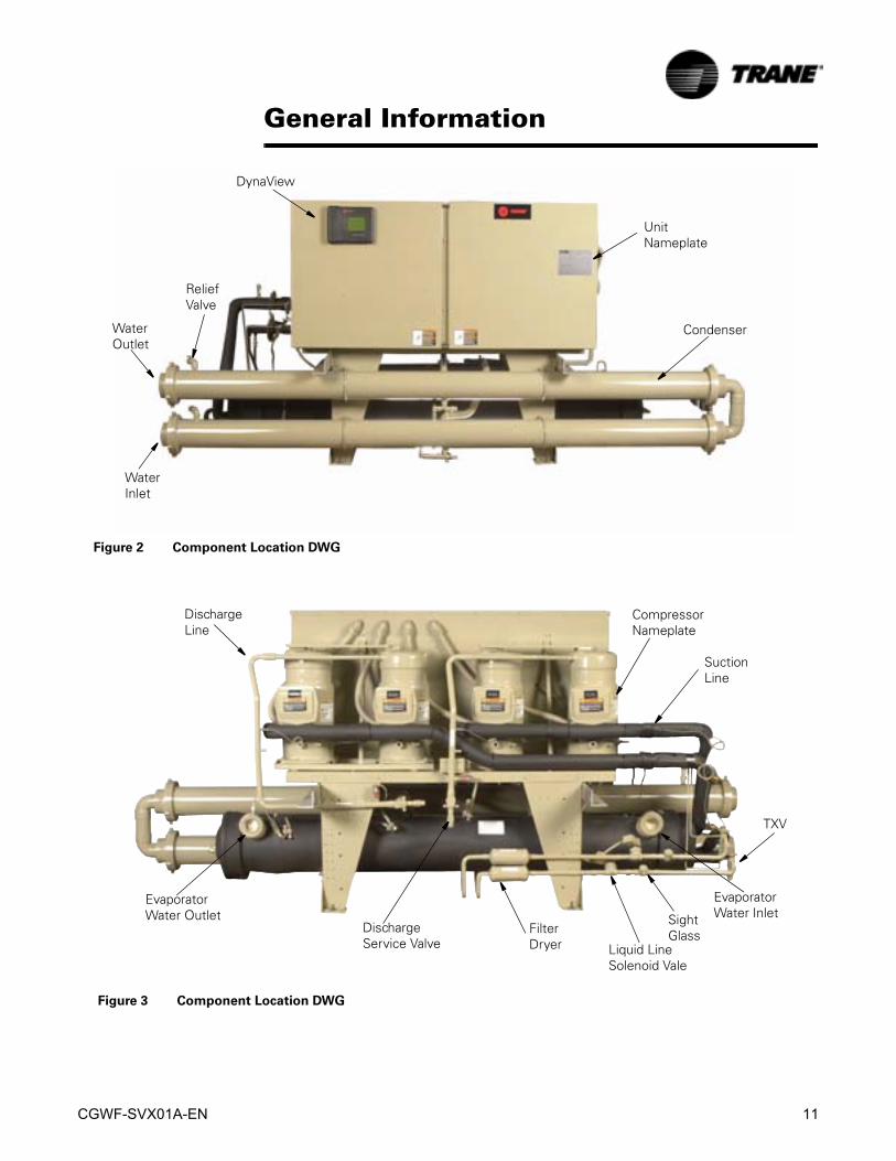
Figure 2 Component Location DWG
UnitNameplate
Condenser
DynaView
WaterInlet
WaterOutlet
ReliefValve
Figure 3 Component Location DWG
EvaporatorWater Inlet
TXV
FilterDryer
EvaporatorWater Outlet
Liquid LineSolenoid Vale
SuctionLine
Discharge Service Valve
SightGlass
DischargeLine
CompressorNameplate
12 CGWF-SVX01A-EN
General Information
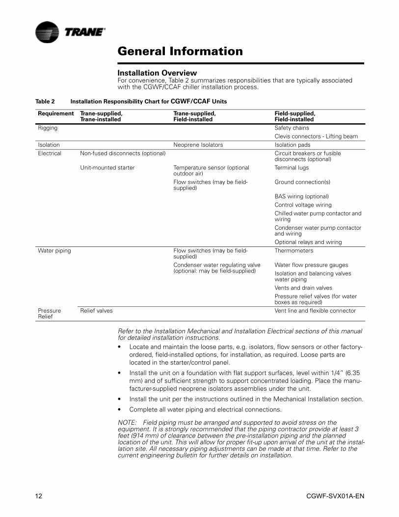
Installation OverviewFor convenience, Table 2 summarizes responsibilities that are typically associated with the CGWF/CCAF chiller installation process.
Refer to the Installation Mechanical and Installation Electrical sections of this manual for detailed installation instructions.• Locate and maintain the loose parts, e.g. isolators, flow sensors or other factory-
ordered, field-installed options, for installation, as required. Loose parts are located in the starter/control panel.
• Install the unit on a foundation with flat support surfaces, level within 1/4” (6.35 mm) and of sufficient strength to support concentrated loading. Place the manu-facturer-supplied neoprene isolators assemblies under the unit.
• Install the unit per the instructions outlined in the Mechanical Installation section.
• Complete all water piping and electrical connections.
NOTE: Field piping must be arranged and supported to avoid stress on the equipment. It is strongly recommended that the piping contractor provide at least 3 feet (914 mm) of clearance between the pre-installation piping and the planned location of the unit. This will allow for proper fit-up upon arrival of the unit at the instal-lation site. All necessary piping adjustments can be made at that time. Refer to the current engineering bulletin for further details on installation.
Table 2 Installation Responsibility Chart for CGWF/CCAF Units
Requirement Trane-supplied, Trane-installed
Trane-supplied, Field-installed
Field-supplied, Field-installed
Rigging Safety chainsClevis connectors - Lifting beam
Isolation Neoprene Isolators Isolation padsElectrical Non-fused disconnects (optional) Circuit breakers or fusible
disconnects (optional)Unit-mounted starter Temperature sensor (optional
outdoor air)Terminal lugs
Flow switches (may be field-supplied)
Ground connection(s)
BAS wiring (optional)Control voltage wiringChilled water pump contactor and wiringCondenser water pump contactor and wiringOptional relays and wiring
Water piping Flow switches (may be field-supplied)
Thermometers
Condenser water regulating valve (optional: may be field-supplied)
Water flow pressure gaugesIsolation and balancing valves water pipingVents and drain valvesPressure relief valves (for water boxes as required)
Pressure Relief
Relief valves Vent line and flexible connector

CGWF-SVX01A-EN 13
General Information• Where specified, supply and install valves in the water piping upstream and
downstream of the evaporator and condenser water boxes, to isolate the shells for maintenance and to balance/trim the system.
• Supply and install condenser water control valve(s) per Trane RLC-EB-4.
• Supply and install flow switches or equivalent devices in both the chilled water and condenser water piping. Interlock each switch with the proper pump starter and CH530, to ensure that the unit can only operate when water flow is estab-lished.
• Supply and install taps for thermometers and pressure gauges in the water pip-ing, adjacent to the inlet and outlet connections of both the evaporator and the condenser.
• Supply and install drain valves on each water box.
• Supply and install vent cocks on each water box.
• Where specified, supply and install strainers ahead of all pumps and automatic modulating valves.
• Supply and install refrigerant pressure relief piping from the pressure relief to the atmosphere.
• If necessary, supply enough refrigerant and dry nitrogen (75 psig) for pressure testing.
• Start the unit under supervision of a qualified service technician.
• Where specified, supply and insulate the evaporator and any other portion of the unit, as required, to prevent sweating under normal operating conditions.
• For unit-mounted starters, cutouts are provided at the top of the panel for line-side wiring.
• Supply and install the wire terminal lugs to the starter.
• Supply and install field wiring to the line-side lugs of the starter.

14 CGWF-SVX01A-EN
General Information
Table 3 General Data CGWF
CGWF
Unit Tonnage 20 25 30 40 50 60
General
Refrigerant Type R-22 R-22 R-22 R-22 R-22 R-22
Refrigerant Charge lb (kg) 50 (23) 50 (23) 90 (41) 50/50 (23/23) 50/50 (23/23) 75/75 (34/34)
Oil Type Oil 31 Oil 31 Oil 31 Oil 31 Oil 31 Oil 31
Oil Charge Pints (l) 16 (7.6) 22 (10.4) 28 (13.2) 16/16(7.6/7.6)
22/22 (10.4/10.4)
28/28 (13.2/13.2)
Operating Weight lb (kg) 1694 (768) 1757 (797) 2249 (1020) 2747 (1246) 2977 (1350) 3905 (1771)
Shipping Weight lb (kg) 1522 (690) 1600 (726) 2014 (914) 2366 (1073) 2626 (1191) 3376 (1531)
Overall Dimensions
Length in (mm) 122.6 (3115) 122.6 (3115) 122.6 (3115) 129.0 (3277) 129.0 (3277) 108.1 (2743)
Width in (mm) 31.4 (797) 31.4 (797) 32.2 (818) 31.3 (797) 31.3 (797) 34 (864)
Height in (mm) 57.8 (1467) 57.8 (1467) 57.8 (1467) 57.8 (1467) 57.8 (1467) 74.6 (1894)
Evaporator
Water Storage gal (l) 11.7 (44) 10.7 (40) 16.4 (62) 25.7 (97) 24 (90) 39.9 (151)
Minimum Flow gpm (l/s) 24 (1.5) 30 (1.9) 36 (2.3) 48 (3.0) 60 (3.8) 84 (5.3)
Maximum Flow gpm (l/s) 72 (4.5) 90 (5.7) 108 (6.8) 144 (9.1) 180 (11.4) 252 (15.9)
Condenser
Water Storage gal (l) 8.9 (34) 8.0 (30) 11.7 (44) 19.9 (75) 18.2 (69) 23.5(89)
Minimum Flow gpm (l/s) 30 (2) 36 (2) 50 (3) 60 (4) 72 (5) 90 (6)
Maximum Flow gpm (l/s) 90 (6) 108 (7) 146 (9) 180 (11) 216 (14) 325 (21)
All weights ±3%Operating weights include refrigerant, oil, and water charges.

CGWF-SVX01A-EN 15
General Information
Table 4 General Data CCAF
CCAF
Unit Tonnage 20 25 30 40 50 60
General
Refrigerant Type R-22 R-22 R-22 R-22 R-22 R-22
Refrigerant Charge lb(kg) Field Field Field Field Field Field
Oil Type Oil 31 Oil 31 Oil 31 Oil 31 Oil 31 Oil 31
Oil Charge Pints(l) 16 (7.6) 22 (10.4) 28 (13.2) 16/16(7.6/7.6)
22/22 (10.4/10.4)
28/28 (13.2/13.2)
Operating Weight lb(kg) 1004 (456) 1079 (490) 1274 (579) 1509 (685) 1808 (821) 1982 (900)
Shipping Weight lb(kg) 1430 (649) 1605 (729) 1836 (834) 1792 (814) 2166 (984) 2494 (1133)
Overall Dimensions
Length in (mm) 80.1 (2035) 80.1 (2035) 80.1 (2035) 102.6 (2607) 102.6 (2607) 102.6 (2607)
Width in (mm) 29.4 (745) 29.4 (745) 29.4 (745) 31.4 (591) 31.4 (591) 31.4 (591)
Height in (mm) 57.8 (1467) 57.8 (1467) 57.8 (1467) 57.8 (1487) 57.8 (1487) 57.8 (1487)
Evaporator
Water Storage gal (l) 11.7 (44) 10.7 (40) 16.4 (62) 25.7 (97) 24 (90) 39.9 (151)
Minimum Flow gpm (l/s) 24 (1.5) 30 (1.9) 36 (2.3) 48 (3.0) 60 (3.8) 84 (5.3)
Maximum Flow gpm (l/s) 72 (4.5) 90 (5.7) 108 (6.8) 144 (9.1) 180 (11.4) 252 (15.9)
All weights ±3%Operating weights include refrigerant, oil, and water charges.
16 CGWF-SVX01A-EN
General Information

CGWF-SVX01A-EN 17
Installation Mechanical
Unit StorageExtended storage of the chiller prior to installation requires the following precautionary measures:1. Do not remove the protective coverings from the control panel.
2. Store the chiller in a dry, vibration-free and secure area.
Periodically check the pressure in each refrigerant circuit to verify that the refrigerant charge is intact. If it is not, contact a qualified service organization and the appropriate Trane sales office.
Location Requirement
Noise ConsiderationLocate the unit away from sound-sensitive areas. If necessary, install the optional isolators under the unit. Refer to “Unit Isolators”. Install vibration isolators in all piping and use flexible electrical conduit. Consult an acoustical engineer for critical applications.
FoundationProvide rigid non warping mounting pads or a concrete foundation of sufficient strength and mass to support the chiller operation weight (i.e. including completed piping, and full operating charges of refrigerant, oil and water). The unit operating weights are provided in Table 3 and Table 4. Once in place, the chiller should be level within 1/4” (6.3 mm) over the length and width. The Trane Company is not responsible for equipment problems resulting from an improperly designed or constructed foundation or for improper installation.
VentilationMake provisions to remove heat generated by unit operation from the equipment room. Ventilation must be adequate to maintain an ambient temperature lower than 125 F (52.5 C). The condenser and evaporator pressure relief valve(s) must be vented in accordance with all local and national codes. Refer to “Pressure Relief Valves”.
DrainageLocate the units near a large capacity drain so that water vessels can be emptied during shut down or repairs. Condensers and evaporators are provided with drain connections. Refer to “Unit Piping”. All local and national codes apply.
RiggingModel CGWF/CCAF chillers should be moved by lifting, if the crate has been removed. Refer to Table 3 and Table 4 for typical unit lifting and operating weights. Figure 4 and Figure 5 show proper lifting methods. When on the shipping skid, the unit can be pushed from one end with a forklift, but should never be lifted using a forklift.Note: Two steel lifting angles, to be used for lifting the unit, are secured to the skid when the unit is shipped (20 -50 ton units only). Hardware is provided to mount the lifting angles on the unit.

18 CGWF-SVX01A-EN
Installation Mechanical
� WARNING
Unit Lifting Capacity!
The capacity of the lifting equipment sued must exceed etc. Then end
with failure to use properly sized lifting equipment could result in death
or serious injury or equipment damage.
� WARNING
Improper Unit Lifting!
Follow the lifting procedure detailed below. Failure to follow the proper
lifting procedure could result in death or serious injury or equipment
damage.
Lifting Procedure for 20-50 Ton CGWF 20-60 and Ton CCAF Units.
1. Remove the two sheet lifting angles from the skid.
2. Remove the unit from the shipping skid. If absolutely necessary, the chiller can be pushed or pulled across a smooth surface as long as it is bolted to the shipping skid.
3. Bolt the lifting angles to the unit as shown in Figure 4. Mount one lifting angle at each end of the unit using the nuts and bolts provided.
4. Tighten each bolt to 70ft-lbs torque.
5. Verify the lifting angle mounting bolts are tightened to 70ft-lbs torque.
6. Install clevis connectors in the 1-1/4” (32 mm) lifting holes provided on each end of the lifting angles (Figure 4).
7. Attach lifting chains or cables to the clevis connectors. Each cable alone must be strong enough to lift the chiller.
8. Attach cables to the lifting beam. Total lifting weight and centers of gravity are listed in Table 5. Required lifting beam dimensions are shown in Figure 4. A rig-ging diagram also ships with each unit. Lifting beam crossbars must be positioned so lifting cables do not contact unit piping or control panel enclosure.
CAUTION
Unit Damage!
To prevent unit damage, position lifting beam crossbars so that cables
do not contact the unit.

CGWF-SVX01A-EN 19
Installation Mechanical
Figure 4 Typical Rigging Setup For CGWF 20-50 Ton and 20-60 Ton CCAF Units.
1. Remove lifting angles from the skid. Remove the angle support bolts from the unit legs. Attach the lift-ing angles as shown and torque the 12 mm bolts to 70 ft-lbs attaching the lifting angle.
2. Use clevis pins for attachment of chains to lifting angles, lifting chains (cables) may be adjusted for level lifting.
3. Do not Forklift Unit.4. All units are heavier on the control panel side. Use
Table 5 to adjust rigging accordingly.5. Minimum beam length 4 ft.
20 CGWF-SVX01A-EN
Installation Mechanical
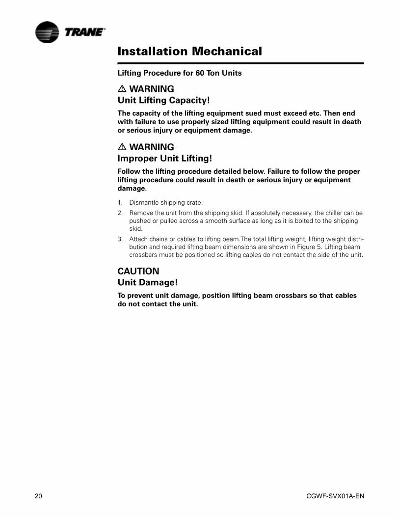
Lifting Procedure for 60 Ton Units
� WARNING
Unit Lifting Capacity!
The capacity of the lifting equipment sued must exceed etc. Then end
with failure to use properly sized lifting equipment could result in death
or serious injury or equipment damage.
� WARNING
Improper Unit Lifting!
Follow the lifting procedure detailed below. Failure to follow the proper
lifting procedure could result in death or serious injury or equipment
damage.
1. Dismantle shipping crate.
2. Remove the unit from the shipping skid. If absolutely necessary, the chiller can be pushed or pulled across a smooth surface as long as it is bolted to the shipping skid.
3. Attach chains or cables to lifting beam.The total lifting weight, lifting weight distri-bution and required lifting beam dimensions are shown in Figure 5. Lifting beam crossbars must be positioned so lifting cables do not contact the side of the unit.
CAUTION
Unit Damage!
To prevent unit damage, position lifting beam crossbars so that cables
do not contact the unit.

CGWF-SVX01A-EN 21
Installation Mechanical
Alternate Moving MethodsIf it is not possible to rig from the previous method shown inFigure 4 and Figure 5, the unit my also be moved by jacking each end high enough to move an equipment dolly under each end of the unit frame. Once securely mounted on the dollies, the unit may be rolled into position. Jacks should be positioned to lift under the lifting angles installed on the unit by the contractor.
Access RestrictionsAll CGWF/ CCAF units will pass through a standard 36-inch doorway. Typical dimensions are shown in Figure 7 - Figure 11.
Figure 5 Typical Rigging Setup For CGWF 60 Ton Units.
1. Use clevis pins for attachment of chains to lifting holes, lifting chains (cables) may be adjusted for level lifting.
2. Do not Forklift Unit.3. All units are heavier on the control panel side. Use
Table 5 to adjust rigging accordingly.4. Minimum beam length 6ft.
Table 5 Center of Gravity Dimensions
Unit Size Location of Center of Gravity (in)
X Y Z
CGWF
20 18 24 925 18 25 930 18 26 940 23 26 850 23 27 960 28 31 13
CCAF
20 28 31 825 28 30 830 28 28 840 33 29 850 33 27 860 33 26 8

22 CGWF-SVX01A-EN
Installation Mechanical
Recommended ClearancesProvide recommended access clearance for service and maintenance operations. Refer to recommendations provided in Figure 7 - Figure 11. Local codes may take precedence over recommendations.
Unit IsolationThere are two mounting methods that will minimize sound and vibration. They are the direct-mount method and the isolator-mount method.
Direct MountingThe unit can be direct-mounted on an isolated concrete pad or on an isolated concrete footing at each end. Refer to Table 3 and Table 4 for unit operating weights. A mounting hole is provided in the base of the unit frame at each mounting location. Provide a means of securely anchoring the unit to the mounting surface. Level the unit carefully. Refer to “Leveling the Unit”.
Neoprene Isolator MountingInstall the optional neoprene mounting isolators at each mounting location. Refer to Table 6 for isolator selection, placement and loading information. Isolators are identified by color and by the isolator part number.Bolt the isolator to the mounting surface. Do not fully tighten the mounting bolts. Mount the unit on the isolators and install a 1/2-inch (13 mm) nut on each isolator positioning pin. Maximum isolator deflection should be 1/4-inch. Level the unit carefully. Refer to “Unit Leveling”. Now fully tighten isolator mounting bolts.
Neoprene Isolator Data
Figure 6 Isolators and Locations
3
1
4
2
Control Panel End
CGWF/CCAF
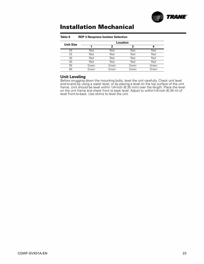
Table 6 RDP 3 Neoprene Isolator Selection
Unit SizeLocation
1 2 3 4
CGWF
20 Green Green Green Green25 Green Green Green Green30 Green Green Green Green40 Gray Gray Gray Gray50 Gray Gray Gray Gray60 Gray Gray Gray Gray
CCAF
CGWF-SVX01A-EN 23
Installation Mechanical
Unit LevelingBefore snugging down the mounting bolts, level the unit carefully. Check unit level end-to-end by using a water level, or by placing a level on the top surface of the unit frame. Unit should be level within 1/4-inch (6.35 mm) over the length. Place the level on the unit frame and check front to back level. Adjust to within1/4-inch (6.35 m) of level front-to-back. Use shims to level the unit.
20 Red Red Red Red25 Red Red Red Red30 Red Red Red Red40 Red Red Red Red50 Green Green Green Green60 Green Green Green Green
Table 6 RDP 3 Neoprene Isolator Selection
Unit SizeLocation
1 2 3 4

24 CGWF-SVX01A-EN
Installation Mechanical
Figure 7 CGWF 20, 25, 30 Ton Unit Dimensions, Recommended Clearances, Mounting Locations,
Electrical, Water Connection Size and Locations
CGWF-SVX01A-EN 25
Installation Mechanical
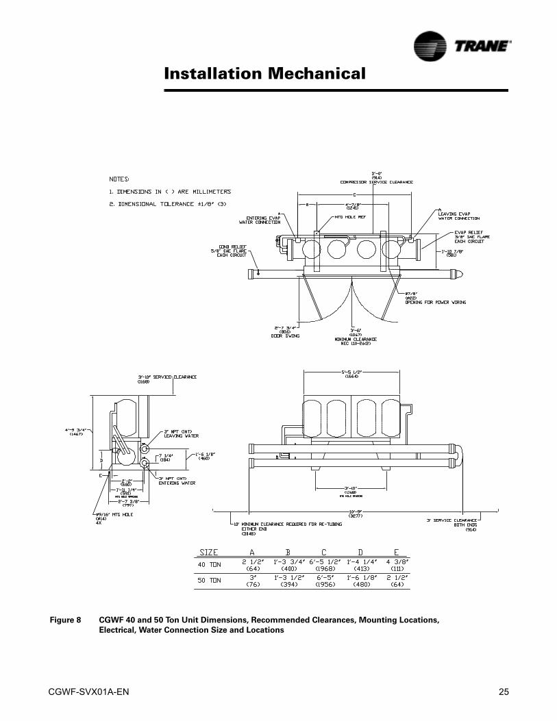
Figure 8 CGWF 40 and 50 Ton Unit Dimensions, Recommended Clearances, Mounting Locations,
Electrical, Water Connection Size and Locations

26 CGWF-SVX01A-EN
Installation Mechanical
Figure 9 CGWF 60 Ton Unit Dimensions, Recommended Clearances, Mounting Locations,
Electrical, Water Connection Size and Locations
CGWF-SVX01A-EN 27
Installation Mechanical
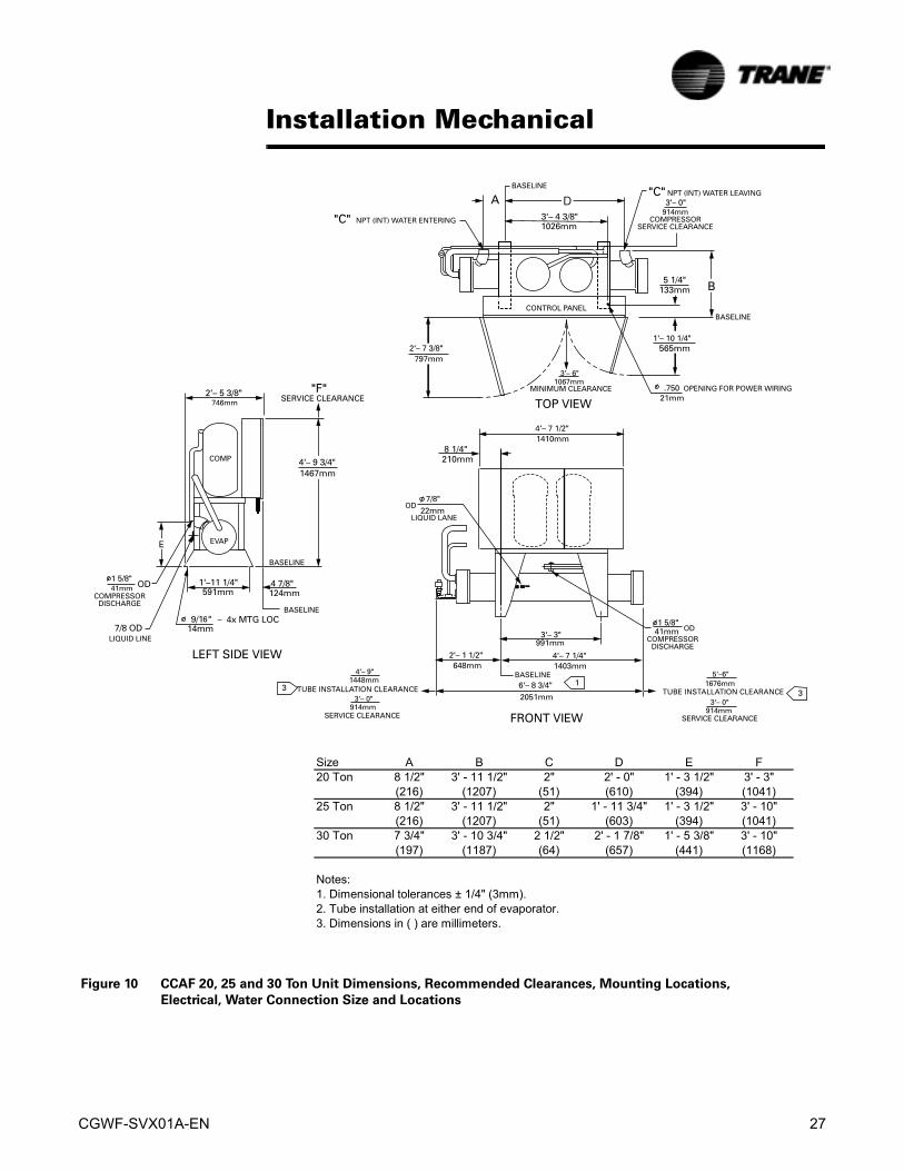
Figure 10 CCAF 20, 25 and 30 Ton Unit Dimensions, Recommended Clearances, Mounting Locations,
Electrical, Water Connection Size and Locations
Size A B C D E F
20 Ton 8 1/2" 3' - 11 1/2" 2" 2' - 0" 1' - 3 1/2" 3' - 3"
(216) (1207) (51) (610) (394) (1041)
25 Ton 8 1/2" 3' - 11 1/2" 2" 1' - 11 3/4" 1' - 3 1/2" 3' - 10"
(216) (1207) (51) (603) (394) (1041)
30 Ton 7 3/4" 3' - 10 3/4" 2 1/2" 2' - 1 7/8" 1' - 5 3/8" 3' - 10"
(197) (1187) (64) (657) (441) (1168)
Notes:1. Dimensional tolerances ± 1/4" (3mm).
2. Tube installation at either end of evaporator.
3. Dimensions in ( ) are millimeters.

28 CGWF-SVX01A-EN
Installation Mechanical
Figure 11 CCAF 40, 50 and 60 Ton Unit Dimensions, Recommended Clearances, Mounting Locations,
Electrical, Water Connection Size and Locations
Size A B C D E F
40 Ton 5' - 1 3/4" 1' - 3 3/4" 1' - 11 1/4" 2 1/2" 3' - 5" 1' - 4 1/4
(1568) (400) (591) (64) (1041) (413)
50 Ton 5' - 1 1/2" 1' - 3 1/2" 2' - 1 1/8" 3" 3' - 10" 1' - 6 1/8"
(1562) (394) (638) (76) (1168) (480)
60 Ton 5' - 1 1/2" 1' - 3 1/2" 2' - 0 7/8" 3" 3' - 10" 1' - 6 1/8"
(1562) (394) (632) (76) (1168) (480)
Notes:1. Dimensional tolerances ± 1/4" (3mm).
2. Tube installation at either end of evaporator.
3. Dimensions in ( ) are millimeters.

CGWF-SVX01A-EN 29
Installation Mechanical
Unit Piping
General Water Piping RecommendationsMake water piping connections to evaporator and condenser(s). Isolate and support piping to prevent stress on the unit. Use flanged ells or spool-pieces to facilitate service procedures. Construct piping according to local and national codes. Insulate and flush piping before connecting to unit.
CAUTION
Equipment Damage!
To prevent equipment damage, bypass the unit if using an acidic
flushing agent.
Use a pipe sealant or teflon tape on all water connections. Minimize heat gain and prevent condensation by insulating all chilled water piping.
CAUTION
Piping Damage!
To prevent damage to water piping, do not over-tighten connections.
Water System
Water Flow RatesEstablish balanced water flow through both the evaporator and condenser. Flow rates should fall between the minimum and maximum values given inTable 3 and Table 4. Flow rates above or below these values can cause equipment damage or improper unit operation.
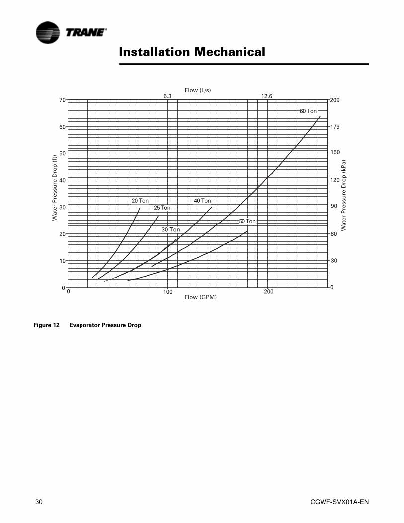
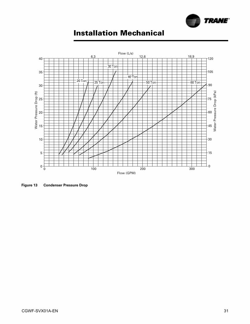
Pressure Drop MeasurementMeasure evaporator water pressure drop at the pressure gauge(s) on the system water piping. Readings should approximate those shown by the pressure drop charts in Figure 12 and Figure 13.Note: Evaporator pressure drop is an approximation and is to be used as a tool to estimate flow rate and as an aid to waterside system piping design. If an accurate measurement of flow rate is required, an accurate flow meter must be installed in the system.
30 CGWF-SVX01A-EN
Installation Mechanical
Figure 12 Evaporator Pressure Drop
Chart PD 1 CGWE Evaporator
CGWF-SVX01A-EN 31
Installation Mechanical
Figure 13 Condenser Pressure Drop

32 CGWF-SVX01A-EN
Installation Mechanical
Evaporator Water Piping
Evaporator Water Connections.Internal NPTF water inlet and outlet connections are used on all 20 through 50 ton CGWF and 20-60 ton CCAF units. 60 ton CGWF use grooved pipe connectors for water inlet and outlet. Evaporator water inlet and outlet types, sizes and locations are shown in Figure 14.
Evaporator Piping ComponentsFigure 14 illustrates typical recommended evaporator piping components. Piping components and layout vary, depending on water source and connection locations. A vent is located on top of the evaporator at the water outlet end. Provide additional vents at high points in the piping to bleed air from the chilled water system. Install pressure gauge(s) to monitor entering and leaving chilled water pressure.
CAUTION
Excessive Water Pressure!
To prevent evaporator damage, do not exceed 300 psi for 20-60 ton CCAF
and 20-50 ton CGWF, and 215 psi for 60 ton CGWF evaporator water
pressure.
Provide shutoff valves in the line(s) to the gauge(s) to isolate the gauges when not in use. Use pipe unions to simplify disassembly for system service. Use vibration eliminators to prevent transmitting vibrations through the water lines.Install thermometers in the lines to monitor evaporator entering and leaving water temperatures. Install a balancing cock in the leaving water line. It will be used to establish a balanced water flow. Both the entering and leaving water lines should have shutoff valves installed to isolate the evaporator for service.
Flow Sensing DevicesChilled water flow switches are optional, but there must be a chilled water flow interlock provided to the MP to indicate that the evaporator pump is running. To provide additional chiller protection, install and wire the flow switch in series with the chilled water pump interlock for the chilled water circuits (refer to “Chilled Water Flow Interlock”). Specific connection and schematic wiring diagrams shipped with the unit.
Figure 14 Recommended Piping
CGWF-SVX01A-EN 33
Installation MechanicalFlow switches must stop or prevent compressor operation if chilled water flow drops off drastically. Follow the manufacturer's recommendations for selection and installation procedures. General guidelines for flow switch installation are outlined below:1. Mount the switch upright with a minimum of 5 pipe diameters straight, horizontal
run on each side. Do not install close to elbows, orifices, or valves.
Note: The arrow on the switch must point in the direction of water flow.
2. To prevent switch fluttering, remove all air from the water systems.
Note: The MP provides a 6-second time delay before shutting the unit down on a loss-of-flow diagnostic. Contact a qualified service organization if nuisance machine shutdowns persist.
Install a pipe strainer in the evaporator water supply line to protect components from water-borne debris.
Evaporator Drain.The evaporator drain connection should be piped to a suitable drain facility to empty the evaporator during service or shutdown. Provide a shutoff valve in the drain line. If the evaporator drain connection is not piped, remove the drain plug from its shipping location in the control panel and install it in the drain connection.
CAUTION
Use Pipe Strainers!
To prevent evaporator or condenser damage, pipe strainers must be
installed in the water supplies to protect components from water born
debris. The Trane Company is not responsible for equipment-only-
damage caused by water born debris.
Condenser Water Piping
Condenser Water Connections.Condenser water inlet and outlet types, sizes and locations are given in Figure 7 - Figure 11.
Condenser Piping Components.Condenser piping components and layout vary, depending on water source and connection locations. Figure 15 illustrates typical piping components for a well water (city water) condensing source. Typical components for a cooling tower condensing source are ALSO shown in Figure 16.Condenser piping components generally function identically to those in the evaporator piping system. Refer to “Evaporator Piping”. In addition, cooling tower systems may include a manual or automatic bypass valve that can alter water flow rate to maintain condensing pressure. Well (city) water condensing systems should include a pressure reducing valve and water regulating valve (Figure 15).A pressure reducing valve should be installed to reduce water pressure entering the condenser. This is required only if water pressure exceeds 300 psig. This is necessary to prevent damage to the disc and seat of the water regulating valve that can be caused by excessive pressure drop through the valve.
34 CGWF-SVX01A-EN
Installation Mechanical
CAUTION
Excessive Water Pressure!
To prevent condenser or regulating valve damage, do not exceed 150 psi
for 30 and 60 ton units and 300 psi for 20, 25, 40 and 50 ton units
condenser water pressure.
The optional water regulating valve(s) maintains condensing pressure and temperature by throttling water flow leaving the condenser in response to compressor discharge pressure. Adjust the regulating valve(s) for proper operation during start-up.
Condenser Drains.The condenser shells can be drained by removing the drain plugs from the bottom of the condenser heads. Also remove the vent plugs (at the top of the condenser heads) to facilitate complete drainage.When the unit is shipped, the condenser drain plugs are located in the control panel along with the evaporator drain plug. The condenser drains can be piped to drain facilities, if desired. If they are not, install the drain plugs in the condenser drain connections on the condenser.

CGWF-SVX01A-EN 35
Installation Mechanical
Water Regulating ValveThe water regulating valve maintains condensing pressure and temperature by throttling water flow leaving the condenser in response to compressor discharge pressure, decreasing water flow as pressure falls, and increasing water flow when discharge pressure rises.Install the valve on the condenser leaving water line (Figure 15). Dual circulated units (40, 50, and 60-ton) require dual regulating valves installed in parallel in the leaving water line (Figure 15).
Figure 15 Components for Condenser Water Circuit
36 CGWF-SVX01A-EN
Installation Mechanical
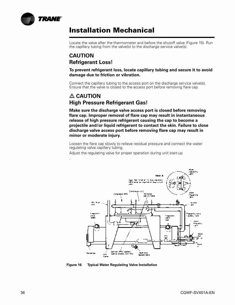
Locate the valve after the thermometer and before the shutoff valve (Figure 15). Run the capillary tubing from the valve(s) to the discharge service valve(s).
CAUTION
Refrigerant Loss!
To prevent refrigerant loss, locate capillary tubing and secure it to avoid
damage due to friction or vibration.
Connect the capillary tubing to the access port on the discharge service valve(s). Ensure that the valve is closed to the access port before removing flare cap.
� CAUTION
High Pressure Refrigerant Gas!
Make sure the discharge valve access port is closed before removing
flare cap. Improper removal of flare cap may result in instantaneous
release of high pressure refrigerant causing the cap to become a
projectile and/or liquid refrigerant to contact the skin. Failure to close
discharge valve access port before removing flare cap may result in
minor or moderate injury.
Loosen the flare cap slowly to relieve residual pressure and connect the water regulating valve capillary tubing.Adjust the regulating valve for proper operation during unit start-up.
Figure 16 Typical Water Regulating Valve Installation
CGWF-SVX01A-EN 37
Installation MechanicalWater Treatment
Using untreated or improperly treated water in these units may result in inefficient operation and possible tube damage. Consult a qualified water treatment specialist to determine whether treatment is needed.
CAUTION
Proper Water Treatment!
The use of untreated or improperly treated water in a Chiller may result
in scaling, erosion, corrosion, algae or slime. It is recommended that the
services of a qualified water treatment specialist be engaged to
determine what water treatment, if any, is required. Trane assume no
responsibility for equipment failures which result from untreated or
improperly treated water, or saline or brackish water.
Water pressure Relief ValvesInstall a water pressure relief valve in the condenser and evaporator leaving chilled water piping (Figure 15). Water vessels with close-coupled shutoff valves have a high potential for hydrostatic pressure buildup on a water temperature increase. Refer to applicable codes for relief valve installation guidelines.
CAUTION
Install Water Relief Valves!
To prevent shell damage, install pressure relief valves in both evaporator
and condenser water systems.
Low Temperature OperationThe leaving water temperature cutout setpoint is adjusted using the DynaView or TechView. There is a minimum differential that must exist between the Chilled Water Setpoint (CWSP) and the Leaving Water Temperature Cutout setpoint (LWTCS). This minimum varies depending on the design DT, the number of cooling stages and whether or not Hot Gas Bypass (HGBP) is installed. The equations to calculate LWTCS are shown below.Leaving Water Temperature Cutout Setpoint (LWTCS) is:20-30 T for units with out HGBP
20-30 T for units with HGBP
40-60 T for units with out HGBP
CWSP ∆T2
------- 2°F+ – LWTCS=
CWSP ∆T2
------- 4°F+ – LWTCS=
CWSP ∆T4
------- 2°F+ – LWTCS=

38 CGWF-SVX01A-EN
Installation Mechanical
40-60 T for units with HGBP
Pressure Relief Valve VentingAll CGWF units utilize two refrigerant-pressure relief valves for each circuit (one high side and one low side) which must be vented to the outdoor atmosphere. The high side relief valves are located at the left end of each condenser at the top (facing the control panel). The low side relief valves are located at the right end of the evaporator.Relief valve connection sizes are 5/8” flare on the condenser and 3/8” flare on the evaporator. CCAF units have evaporator relief valve(s) only.All relief valve venting is the responsibility of the installing contractor.Vent pipe size must conform to the ANSI/ASHRAE Standard 15 for vent pipe sizing. All federal, state, and local codes take precedence over any suggestions stated in this manual.Consult local regulations for any special relief line requirements.
CAUTION
Proper Vent Piping!
Vent piping must be installed to code specifications. Failure to heed
specifications could result in capacity reduction, unit damage and/or
relief valve damage.
Once the relief valve has opened, it will re-close when pressure is reduced to a safe level. The valve may leak and should be replaced.Pipe each relief valve on the unit into a common vent line. Provide an access valve on the common line to connect vacuum pump discharge and vent excess refrigerant out of the mechanical room. The access valve must be located at the low point of the vent piping to enable draining of any condensate that may accumulate in the piping.
Table 7 Percent Glycol and Freeze Solution Temperatures
% Glycol
Ethylene Glycol Propylene Glycol
Solution Freeze Point (°F) Solution Freeze Point (°F
0 32 325 29 29.310 25.5 26.415 21.5 23.120 16.8 19.325 11.4 14.830 5.1 9.335 -2.3 2.740 -10.8 -5.245 -20.7 -14.650 -32.1 -25.854 -42.3 -36.1
CWSP ∆T4
------- 4°F+ – LWTCS=

CGWF-SVX01A-EN 39
Installation Mechanical
� WARNING
Confined Space Hazards!
Do not work in confined spaces where sufficient quantities of a
refrigerant or other hazardous, toxic or flammable gas may be leaking.
Refrigerant or other gases could displace available oxygen to breathe,
causing possible asphyxiation or other serious health risks. Some gases
may be flammable and or explosive. Evacuate the area immediately and
contact the proper rescue or response authority. Failure to take
appropriate precautions or to react properly to a potential hazard could
result in death or serious injury.
Table 8 Pressure Relief Valve Data
Valve location Quantity Relief Pressure (psi)
Rated Capacity per Relief Valve (lba/min.)
Pipe size(in)
Condenser20-50 ton
1 per ckt 450 37.6 5/8” flare
Condenser60 ton
1 per ckt 450 37.6 5/8” flare
Evaporator 1 per ckt 300 11.5 3/8” flare

40 CGWF-SVX01A-EN
Installation Mechanical
Refrigerant Piping (CCAF only)Refer to the “Trane Reciprocating Refrigeration Manual” for refrigerant piping selection information. Refrigerant pipe size selected must be within the velocity and pressure drop limitations required for proper system operation. It is essential that refrigerant piping be properly sized and applied since these factors have a significant effect on performance.
NOTE: Use Type L refrigerant grade copper tubing only. The use of a lower grade tubing can cause operating problems.
Liquid Line Components and ConnectionsLiquid line connections sizes and locations are shown in Figure 10 - Figure 11. Thermostatic expansion valves, refrigerant sight glass, solenoid valves and schraeder valves are standard components on CCAF liquid lines. A liquid line filter drier must be installed for each circuit. Install a liquid line service valve in the liquid line to isolate the drier for service.
Liquid Line SizingTrane recommends sizing the liquid line diameter as small as possible while maintaining acceptable pressure drop. This will minimize the required refrigerant charge and increase compressor life.Liquid risers in a system an additional 0.5 psig pressure drop per each foot of vertical rise. If the riser is length exceeds 15 feet, a larger diameter and/or shorter liquid line may be required to provide required subcooling at the expansion valve. The line does not have to be pitched. Basic liquid line sizing perimeters for these units are:
Liquid lines are not usually insulated. If, however, the line runs through an area of high ambient temperature (i.e. boiler room), subcooling my drop below required levels. Liquid line passing though these warm spaces should be insulated.
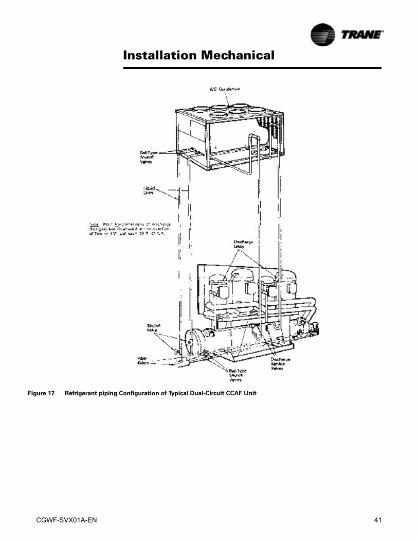
Discharge (hot gas) LinesPitch discharge lines in the direction of hot gas flow at the rate of 1/2-inch per each 10 feet of horizontal run. Discharge line sizing is based on required velocity to provide good oil movement. Basic discharge line parameters are:
Liquid Velocity 100-250 fpm
Maximum allowable pressure drop 3-6 psig (1F)
Maximum allowable pressure drop 6 psig (1F) 6 psig (1F)
Maximum Velocity 3500 fpm
Minimum Velocity (at minimum load)
Horizontal lines 500 fpm
Vertical lines (up flow) 1000 fpm
CGWF-SVX01A-EN 41
Installation Mechanical
Figure 17 Refrigerant piping Configuration of Typical Dual-Circuit CCAF Unit
42 CGWF-SVX01A-EN
Installation Mechanical
Leak TestOnce refrigerant piping is complete, thoroughly test the system for leaks.
System EvacuationFor field evacuation, use a rotary-style vacuum pump capable of pulling a vacuum of 100 microns or less. Follow the pump manufacture’s instructions for proper use of the pump. The line used to connect the pump to the system should be copper and of the largest diameter that can practically be used. Using a larger line size with minimum flow resistance can significantly reduce evacuation time.Rubber or synthetic hose are not recommended for unit evacuation because they have moisture absorbing characteristics which result in excessive outgassing and pressure rise during the standing vacuum test. This makes it impossible to determine if the unit has a leak, contains excessive moisture, or is experiencing a continual high rate of pressure increase due to the hoses.
NOTE: Insure that all sections of the refrigerant system are properly evacuated.
CAUTION
Equipment Damage!
Do not use a megohm meter or apply power to compressor windings
under vacuum. This may damage motor windings.
Refrigerant ChargingOnce the system is properly installed, leak tested and evacuated, refrigerant charging can begin. Liquid refrigerant must be charged into each circuit through the liquid line access valve with the compressor(s) off.
CAUTION
Equipment Damage!
To prevent evaporator tube rupture, never charge liquid refrigerant into a
water vessel when refrigerant temperature/pressure relationship of the
vessel is below freezing.
Charge refrigerant into the system by weight. Use an accurate scale or charging cylinder to determine the exact charge entering the system. Failure to charge the system accurately can lead to under or over-charging and result in unreliable operation.If system pressure equalize before the full charge enters the system, close the charging port and proceed to “Start-up Procedure”. Once the unit is operating, add the remainder of the required charge to the system.
CGWF-SVX01A-EN 43
Installation Electrical
General RecommendationsThe wiring procedures described in this portion of the manual must be accomplished to obtain proper operation of the basic CGWF/CCAF unit. Electrical wiring instructions for all optional features and equipment are described In the “Optional Electrical Wiring” sections of this manual.
� WARNING
Hazardous Voltage!
Disconnect all electric power, including remote disconnects before
servicing. Follow proper lockout/tagout procedures to ensure the power
can not be inadvertently energized. Failure to disconnect power before
servicing could result in death or serious injury.
All wiring must comply with National Electric Code (NEC) and state and local requirements. Outside the United States, the national and/or local electrical requirements of the other countries shall apply. The installer must provide properly sized system interconnecting and power supply wiring with appropriate branch circuit protection. Type and locations of disconnects must comply with all applicable codes.
CAUTION
Use Copper Conductors Only!
Unit terminals are not designed to accept other types of conductors.
Failure to use copper conductors may result in equipment damage. All
wiring must comply with applicable local and national codes.
Electrical connection locations are shown in Figure 7 - Figure 11. Minimum circuit ampacities, recommended fuse sizes and other unit electrical data are provided in Table 10 and Table 11, and on the unit nameplate. Refer to the “Field Wiring and Remote Sensor Layout Schematic” shown in the Unit Wiring section.
Power Supply Wiring
Unit Power SupplyThe installer must connect appropriate line power supply (with fused disconnects) to the terminal block or non-fused, unit mounted disconnect in the power section of the unit control panel. Refer to Figure 2 and Figure 3. Field wiring diagrams, electrical schematics and component location drawings are also attached to the inside of the control panel door.The unit power fused disconnect switch(es) should be located in the general area of the unit to comply with NEC or local codes. The unit disconnect can be used as an emergency shutdown device.Normally, manual shutdown of the unit is accomplished at the DynaView. Then, open the line power and control power (if used) fused disconnects after the pumpdown cycle is complete.
Equipment GroundsProvide proper grounding at the connection points provided in the panel (Figure 22).
Terminal Lugs, Circuit Breakers and Non-Fused Disconnect SwitchesProper starter/control panel line-side lug sizes are specified on the starter submittals and in Table 9. These lug sizes must be compatible with conductor sizes specified by the electrical engineer or contractor.

44 CGWF-SVX01A-EN
Installation Electrical
Figure 18 Electrical Installation
Table 9 Customer Wire Selection
Unit Size Unit Voltage Disconnect Switch Size Connection Wire Range
Power wire Selection to Disconnect Switch (1S1)
30-50 Ton 208/230 Volt 250 Amp (1) #1-300 MCM20-50 Ton 460 Volt 100 Amp (1) #14-1/020-60 Ton 575 Volt 100 Amp (1) #14-1/020-25 Ton 208/230 Volt 100 Amp (1) #14-1/060 Ton 208/230/460 Volt 250 Amp (1) #4-350 MCMPower Wire Selection to Disconnect Switch (1S1) High Condensing Temperature(90-130 F) Units
25-50 Ton 208/230 Volt 225 Amp (1) #1-300 MCM60 Ton 208/230 Volt 400 Amp (1) 250-500 MCM20-50 Ton 460 Volt 100 Amp (1) #14-1/020-60 Ton 575 Volt 100 Amp (1) #14-1/060 Ton 460 Volt 250 Amp (1) #4-350 MCM20 Ton 208/230 Volt 100 Amp (1) #14-1/0Power Wire Selection to Main Terminal Block
20-60 Ton 460/575 Volt 250 Amp (1) #12-2/020-40 Ton 208/230 Volt 250 Amp (1) #12-2/050-60 Ton 208/230 Volt 250 Amp (1) #6-350 MCM
Control Wire Selection For 30 Volt or Less Circuits
Wire Size Maximum Length
14 AWG 5000 ft16 AWG 2000 ft18 AWG 1000 ft

CGWF-SVX01A-EN 45
Installation Electrical
Table 10 Electrical Data CGWF Standard Condensing Temperature Units
Unit Size Unit Wiring Data Compressor Motor Data
Rated Voltage
Minimum Circuit Ampac-ity
Max Fuse Size Recommended Duel Element Fuse Size
Qty - Size RLA LRA
20 208/230 77 110 100 2 -10 34 251380 38 50 50 17 142460 32 45 40 14 117575 27 40 40 12 94400/50 32 50 50 14 110
25 208/230 99 150 125 1 -151 - 10
52/34 376/251380 51 70 70 27/17 215/142460 43 60 60 23/14 178/117575 35 50 45 18/12 143/94400/50 42 50 45 22/14 174/110
30 208/230 117 150 150 2 - 15 52 376380 61 80 80 27 215460 52 70 70 23 178575 41 50 50 18 143400/50 50 80 80 22 174
40 208/230 145 175 175 4 - 10 34 251380 72 80 90 17 142460 60 70 70 14 117575 51 60 70 12 94400/50 60 90 90 14 110
50 208/230 185 225 225 2 - 152 - 10
52/34 376/251380 95 110 110 27/17 215/142460 80 100 100 23/14 178/117575 65 80 80 18/12 143/94400/50 78 110 125 22/14 174/110
60 208/230 221 250 250 4 - 15 52 376380 115 125 150 27 215460 98 110 110 23 178575 77 90 90 18 143400/50 94 125 150 22 174
Notes:1. Minimum Circuit Ampacity is 125% of the largest compressor RLA plus 100% of the remaining compressor(s) RLA, per NEC 440-32 and NEC 440-33.2. Maximum Fuse Size is 225% of the largest compressor RLA plus 100% of the remaining compressor(s) RLS, per NEC 440-30.3. Recommended Dual-Element Fuse Size is 175% of the largest compressor RLA plus 100% of the remaining compressor(s) RLA, Per NEC 430-152.4. Use copper conductors only.5.Compressor motor Voltage utilization range is:Rated Voltage--- Utilization Range208/230 ---188-253380 ---342-418460 ---414-506575 ---517-633400/50 - 360-440

46 CGWF-SVX01A-EN
Installation Electrical
Table 11 Electrical Data CCAF and CGWF High Condensing Temperature (90-130 F) Units
Unit Size Unit Wiring Data Compressor Motor Data
Rated Voltage
Minimum Circuit Ampacity
Max Fuse Size
Recommended Duel Element Fuse Size
Qty - Size RLA LRA
20 208/230 88 125 110 2 -10 39 251380 45 60 60 20 142460 38 50 50 17 117575 32 45 40 14 94400/50 38 50 50 17 117
25 208/230 112 150 150 1 -151 - 10
58/39 376/251380 59 80 80 31/20 215/142460 50 70 70 26/17 178/117575 40 60 60 21/14 143/94400/50 48 70 70 25/17 178/117
30 208/230 131 175 175 2 - 15 58 376380 70 100 90 31 215460 59 80 80 26 178575 47 60 60 21 143400/50 56 80 80 25 178
40 208/230 166 200 200 4 - 10 39 251380 85 100 100 20 142460 72 80 90 17 117575 60 70 70 14 94400/50 72 80 90 17 117
50 208/230 209 250 250 2 - 152 - 10
58/39 376/251380 110 125 150 31/20 215/142460 93 110 110 26/17 178/117575 75 90 90 21/14 143/94400/50 90 110 110 25/17 178/117
60 208/230 247 300 300 4 - 15 58 376380 132 150 150 31 215460 111 125 125 26 178575 89 100 110 21 143400/50 106 125 125 25 178
Notes:1. Minimum Circuit Ampacity is 125% of the largest compressor RLA plus 100% of the remaining compressor(s) RLA, per NEC 440-32 and NEC 440-33.2. Maximum Fuse Size is 225% of the largest compressor RLA plus 100% of the remaining compressor(s) RLS, per NEC 440-30.3. Recommended Dual-Element Fuse Size is 175% of the largest compressor RLA plus 100% of the remaining compressor(s) RLA, Per NEC 430-152.4. Use copper conductors only.5.Compressor motor Voltage utilization range is:Rated Voltage--- Utilization Range208/230 ---188-253380 ---342-418460 ---414-506575 ---517-633400/50 - 360-440

CGWF-SVX01A-EN 47
Installation Electrical
Scroll Compressor Electrical PhasingIt is important that proper rotation of the scroll compressor be established before the machine is started. Proper motor rotation requires confirmation of the electrical phase sequence of the power supply. The motor is internally connected for clockwise rotation with the inlet power supply phased A,B,C.To confirm the correct phase sequence (ABC), use a Model 45 Associated Research Phase indicator or equivalent.Basically, voltages generated in each phase of a polyphase alternator or circuit are called phase voltages. In a three-phase circuit, three sine wave voltages are generated, differing in phase by 120 electrical degrees. The order in which the three voltages of a three-phase system succeed one another is called phase sequence or phase rotation. This is determined by the direction of rotation of the alternator. When rotation is clockwise, phase sequence is usually called “ABC”, when counterclockwise, “CBA”.This direction may be reversed outside the alternator by interchanging any two of the line wires. It is this possible interchange of wiring that makes a phase sequence indicator necessary if the operator is to quickly determine the phase rotation of the motor.
Correcting Improper Electrical Phase SequenceProper compressor motor electrical phasing can be quickly determined and corrected before starting the unit. Use a quality instrument such as an Associated Research Model 45 Phase Sequence Indicator and follow this procedure.
� WARNING
Hazardous Voltage!
During installation, testing, servicing and troubleshooting of this
product, it may be necessary to work with live electrical components.
Have a qualified licensed electrician or other individual who has been
properly trained in handling live electrical components perform these
tasks. Failure to follow all electrical safety precautions when exposed to
live electrical components could result in death or serious injury.
1. Turn Chiller off.
2. Open the electrical disconnect or circuit protection switch that provides line power to the line power terminal block (1TB1) in the control panel (or to the unit-mounted disconnect 1S1).
3. Connect the phase sequence indicator leads to 1TB1 (or 1S1) as follows:
4. Turn power on by closing the unit supply power fused disconnect switch.
5. Read the phase sequence displayed on the indicator. The “ABC” LED on the face of the phase indicator will glow if phase sequence is ABC.
6. If the “CBA” indicator glows instead, open the unit main power disconnect and switch two line leads on 1TB1 (1S1). Reclose the main power disconnect and recheck phasing.
7. Reopen the unit disconnect and disconnect the phase indicator.
Phase Seq. Lead 1TB1 Terminal
Black (Phase A) 1Red (Phase B) 2
Yellow (Phase C) 3

48 CGWF-SVX01A-EN
Installation Electrical
Unit VoltageElectrical power to the unit must meet stringent requirements for the unit to operate properly. Total voltage supply and voltage imbalance between phases should be within the following tolerances.
� WARNING
Hazardous Voltage!
During installation, testing, servicing and troubleshooting of this
product, it may be necessary to work with live electrical components.
Have a qualified licensed electrician or other individual who has been
properly trained in handling live electrical components perform these
tasks. Failure to follow all electrical safety precautions when exposed to
live electrical components could result in death or serious injury.
Voltage Supply
Measure each leg of supply voltage at all line voltage disconnect switches. Readings must fall within the voltage utilization range shown on the unit nameplate. If voltage on any leg does not fall within tolerance, notify the power company to correct this situation before operating the unit. Inadequate voltage to the unit will cause control components to malfunction and shorten the life of relay contacts and compressor motors.
Voltage ImbalanceExcessive voltage imbalance between phases in a three-phase system will cause motors to overheat and eventually fail. Maximum allowable imbalance is 2 percent. Voltage imbalance is defined as 100 times the maximum deviation of the three voltages (three phase) subtracted from the average (without regard to sign), divided by the average voltage.Example:If the three voltages measured at the line voltage fused disconnect are 221 volts, 230 volts and 227 volts, the average would be:
The percentage of imbalance is then:
In the example above 221 is used because it is the farthest from the average. The 2.2 percent imbalance that exists exceeds maximum allowable imbalance by 0.2 percent. This much imbalance between phases can equal as much as 20 percent current imbalance with a resulting increase in winding temperature that will decrease compressor motor life.
Control Power SupplyA panel-mounted control power transformer is standard on all units.
Modules Connections for Interconnecting WiringThe wiring procedures described in this portion of the manual must be completed panel mounted LLIDs. Refer to Filed Wiring on page 95.
221+230+227= 226 Volts
3
100(226-221)= 2.2%
226

CGWF-SVX01A-EN 49
Installation Electrical
Chilled Water Flow SwitchCH530 has an input that accepts a contact closure from a proof-of-flow device such as a flow switch or pressure switch. When this input does not prove flow within a fixed time relative to transition from Stop to Auto modes of the chiller, or if the flow is lost while the chiller is in the Auto mode of operation, the chiller will be inhibited from running by a non-latching diagnosticThe installer must provide a flow sensing device or a pump interlock. Refer also to the “field wiring” diagrams attached to the inside of the control panel door.
Chilled Water Pump ControlCH530 has an evaporator water pump output relay that closes when the chiller goes into the Auto mode. The contact is opened to turn off the pump in the event of most diagnostics to prevent the build up of pump heat.
Condenser Water Loss of Flow ProtectionCH530 has an input that accepts a contact closure from a proof-of-flow device such as a flow switch or pressure switch. When this input does not prove flow within a fixed time from when the pump is commanded on, or if the flow is lost while a compressor is running, the chiller will be inhibited from running by a diagnostic.The installer must provide a flow sensing device or a pump interlock. Refer also to the “field wiring” diagrams attached to the inside of the control panel door.
Condenser Water Pump StarterCH530 has a condenser water pump output relay that closes to indicate when the condenser water pump should be started and opens to indicate when the pump should stop. If condenser pumps are arranged in a bank with a common header, the output can be used to control an isolation valve and/or signal another device that an additional pump is required.
Programmable RelaysCH530 provides a flexible alarm or chiller status indication to a remote location through a hard wired interface to a dry contact closure. Four relays are available for this function, and they are provided (generally with a Quad Relay Output LLID) as part of the Alarm Relay Output Option.The events/states that can be assigned to the programmable relays are listed in the following table.
Table 12 Chiller Events/Status Descriptions
Event/State Description
Alarm - Latching This output is true whenever there is any active latching diagnostic that targets the Chiller, Circuit, or any of the Compressors on a circuit.
Alarm - Auto Reset This output is true whenever there is any active non-latching diagnostic that targets the Chiller, Circuit, or any of the Compressors on a circuit.
Alarm This output is true whenever there is any active latching or non-latching diagnostic that tar-gets the Chiller, Circuit, or any of the Compressors on a circuit.
Warning This output is true whenever there is any active latching or non-latching informational diag-nostic that targets the Chiller, Circuit, or any of the Compressors on a circuit.
Chiller Limit Mode This output is true whenever the chiller has been running in one of the limit modes (Con-denser, Hot Evaporator Start, Demand or Compressor Inhibit) continuously for the debounce time. A given limit or overlapping of different limits must be in effect continuously for the debounce time prior to the output becoming true. It will become false if no limits are present for the debounce time.
Compressor Running The output is true whenever any compressors are running.
Maximum Capacity The output is true whenever the chiller has reached maximum capacity continuously for the debounce time. The output is false when the chiller does not have all its available compres-sors running continuously for the debounce time. See the Maximum Capacity specification for more information.
50 CGWF-SVX01A-EN
Installation Electrical
The CH530 Service Tool (TechView) is used to install and assign any of the above listed events or status to each of the four relays provided with this option.The default assignments for the four available relays are listed below.
External Auto/StopCH530 accepts an isolated contact closure input to request STOP or AUTO command modes from a remote device. The contact closure status is monitored by a CH530 binary input. Contact closure represents an AUTO request, and contact opening represents a STOP request.
Compressor Inhibit/ High Ambient OperationCompressor Inhibit prevents the second compressor on all circuits from running which lowers the overall power consumption and cooling capacity of the chiller. This feature may be invoked by an optional hardware input or a BAS command.Reduce Power Consumption: The 20 - 60 Ton chiller does not have a current limit feature. This feature can be used to lower power consumption by limiting the number of compressors available to the chiller.High Ambient Operation: To minimize high pressure cutouts in high ambient conditions, a thermostat can be connected to the external input to prevent operation of the 2nd compressor on each circuit.
Condenser Water Temperature Sensor ConnectionsWhen the optional condenser water temperature monitoring feature is specified, a pair of sensors are installed in the entering and leaving condenser water boxes.
Chilled Water RestThe MP shall reset the chilled water temperature setpoint based on either return water temperature, or outdoor air temperature. The Return Reset option is standard, Outdoor Reset is optional.The following shall be selectable:1. Reset Type Setpoint.
2. RESET RATIO Setpoints.
3. START RESET Setpoints.
4. MAXIMUM RESET Setpoints.
When the chiller is running, if any type of CWR is enabled, the MP will step the CWS toward the desired CWS' at a rate of 1 degree F every 5 minutes until the Active CWS equals the desired CWS'. When the chiller is not running the CWS shall be fully reset immediately (within one minute). The chiller will then start at the Differential to Start value above a fully reset CWS or CWS' for Outdoor, Return, and Constant Return Reset.
Table 13 Programable Relays
LLID Name LLID Software Relay Designation
Output Name
Operating Status Programmable Relays
Relay 0 Status Relay 4, J2-1,2,3 Relay 1 Status Relay 3, J2-4,5,6 Relay 2 Status Relay 2, J2-7,8,9 Relay 3 Status Relay 1, J2-10,11,12
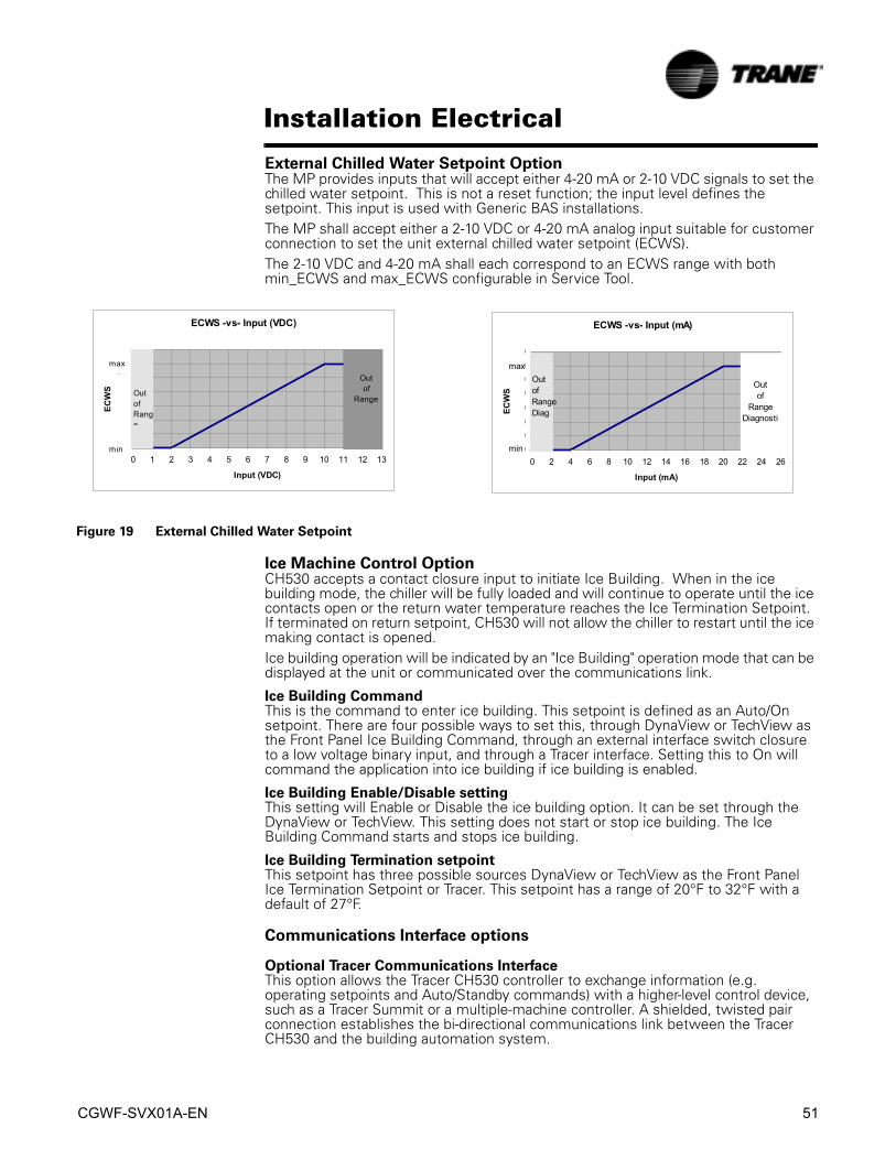
CGWF-SVX01A-EN 51
Installation Electrical
External Chilled Water Setpoint OptionThe MP provides inputs that will accept either 4-20 mA or 2-10 VDC signals to set the chilled water setpoint. This is not a reset function; the input level defines the setpoint. This input is used with Generic BAS installations.The MP shall accept either a 2-10 VDC or 4-20 mA analog input suitable for customer connection to set the unit external chilled water setpoint (ECWS).The 2-10 VDC and 4-20 mA shall each correspond to an ECWS range with both min_ECWS and max_ECWS configurable in Service Tool.
Ice Machine Control OptionCH530 accepts a contact closure input to initiate Ice Building. When in the ice building mode, the chiller will be fully loaded and will continue to operate until the ice contacts open or the return water temperature reaches the Ice Termination Setpoint. If terminated on return setpoint, CH530 will not allow the chiller to restart until the ice making contact is opened.Ice building operation will be indicated by an "Ice Building" operation mode that can be displayed at the unit or communicated over the communications link.
Ice Building CommandThis is the command to enter ice building. This setpoint is defined as an Auto/On setpoint. There are four possible ways to set this, through DynaView or TechView as the Front Panel Ice Building Command, through an external interface switch closure to a low voltage binary input, and through a Tracer interface. Setting this to On will command the application into ice building if ice building is enabled.
Ice Building Enable/Disable settingThis setting will Enable or Disable the ice building option. It can be set through the DynaView or TechView. This setting does not start or stop ice building. The Ice Building Command starts and stops ice building.
Ice Building Termination setpointThis setpoint has three possible sources DynaView or TechView as the Front Panel Ice Termination Setpoint or Tracer. This setpoint has a range of 20°F to 32°F with a default of 27°F.
Communications Interface options
Optional Tracer Communications InterfaceThis option allows the Tracer CH530 controller to exchange information (e.g. operating setpoints and Auto/Standby commands) with a higher-level control device, such as a Tracer Summit or a multiple-machine controller. A shielded, twisted pair connection establishes the bi-directional communications link between the Tracer CH530 and the building automation system.
Figure 19 External Chilled Water Setpoint
ECWS -vs- Input (VDC)
010203040506070
0 1 2 3 4 5 6 7 8 9 10 11 12 13
Input (VDC)
ECW
S
Outof
RangeOutofRange
max
min
ECWS -vs- Input (mA)
010203040506070
0 2 4 6 8 10 12 14 16 18 20 22 24 26
Input (mA)
ECW
S
Outof
RangeDiagnosti
OutofRangeDiag
max
min

52 CGWF-SVX01A-EN
Installation Electrical
To prevent control malfunctions, do not run low voltage wiring (<30 V) in conduit with conductors carrying more than 30 volts.
Field wiring for the communication link must meet the following requirements:• All wiring must be in accordance with the NEC and local codes.
• Communication link wiring must be shielded, twisted pair wiring (Belden 8760 or equivalent). See the table below for wire size selection
:
• The communication link cannot pass between buildings.
• All units on the communication link can be connected in a “daisy chain” configuration.
LonTalk Communications Interface for Chillers (LCI-C) OptionCH530 provides an optional LonTalk Communication Interface (LCI-C) between the chiller and a Building Automation System (BAS). An LCI-C LLID shall be used to provide "gateway" functionality between a LonTalk compatible device and the Chiller. The inputs/outputs include both mandatory and optional network variables as established by the LonMark Functional Chiller Profile 8040.Installation Recommendations
• 22 AWG Level 4 unshielded communication wire recommended for most LCI-C installations
• LCI-C link limits: 4500 feet, 60 devices
• Termination resistors are required
– 105 ohms at each end for Level 4 wire– 82 ohms at each end for Trane "purple" wire
• LCI-C topology should be daisy chain
• Zone sensor communication stubs limited to 8 per link, 50 feet each (maximum)
• One repeater can be used for an additional 4500 feet, 60 devices, 8 communication stubs
Table 14 Wire Size
Wire Size Maximum Length of Communication Wire
14 AWG (2.5 mm2) 5,000 FT (1525 m)16 AWG (1.5 mm2) 2,000 FT (610 m)18 AWG (1.0 mm2) 1,000 FT (305 m)
Table 15 LonTalk Points List
Inputs
Chiller Enable/Disable CommandChilled Water SetpointCurrent Limit SetpointChiller Mode (i.e. Heat, Cool, Free Cool, Ice)Outputs
Run Modes (i.e. Off, Starting, Running, Shutting Down)Operating Modes (i.e.Heat, Cool, Free Cool, Ice)State (Alarm, Run Enabled, Local Control, Limited)Active Chilled/Hot Water SetpointActual Capacity (Percent Rated Load Amps)Active Current Limit SetpointEvaporator Leaving Water TemperatureEvaporator Entering Water TemperatureCondenser Entering Water TemperatureCondenser Leaving Water Temperature

CGWF-SVX01A-EN 53
Installation Electrical
Alarm Description 1Maximum CapacityHot Gas BypassCompressor Running OutputsCondenser Fan Running OutputsEvaporator Water Pump RequestEvaporator Water Flow Status Condenser Water Pump RequestCondenser Water Flow Status Outdoor Air TemperatureEvaporator Refrigerant Pressure Per CircuitEvaporator Refrigerant Temperature Per CircuitCondenser Refrigerant Pressure Per CircuitCondenser Refrigerant Temperature Per CircuitCurrent Per LineCompressor StartsCompressor Run TimeNote 1: Alarm Description denotes alarm severity and description of event Severity: no alarm, warning, normal shutdown, immediate shutdownNote 2: Regenerating, Refrigeration Circuit On, Pumping Out
Table 15 LonTalk Points List

54 CGWF-SVX01A-EN
Installation Electrical
CCAF - Fan ControlOn air cooled chillers, heat is removed from the evaporator water loop and released to ambient air by the condenser. In order to control condensing conditions, the volume of airflow is changed to compensate for ambient air temperature and cooling load. Starting and stopping condensing fans controls airflow.
Outdoor Air Temperature ControlCondenser fan staging is on a per circuit basis and is a function of outdoor ambient temperature and load. The load parameter used is the number of compressors running per circuit. Fans for the various units are staged as shown in the following figures. In the chart, there are areas where more than 1 choice is possible, 1 or 2 fans for example. These are areas of hysteresis in which the current number of fans running is maintained. The number of fans running will depend upon the direction entered. When the circuit is not running the number of fans running will be initialized to 0. When the first compressor starts on a circuit, the minimum number of fans shall be started based on the outdoor air temperature, i.e. if outdoor air temperature is in a hysteresis range, use the smallest number for that range. There should always be at least one fan running when a compressor is running. Staging compressors is a horizontal movement on the fan control charts. If this movement is into a hysteresis area, then the previous number of fan stages is used.Each refrigeration circuit has two relay outputs for fan control. Depending upon how many fans are connected to each circuit, there may be either two or three air flow levels. The number of fan stages is shown on the following table for each unit size.
For 20 and 40 ton chillers, the first fan relay will be on whenever a compressor is running. The second relay will be energized when more condenser cooling is required and de-energized when less cooling is required. The 25, 30, 50, and 60 ton chillers have 3 stages of fan flow. The first relay will be connected to one fan. The second relay will be connected to two fans. For these chillers the first relay will not always be energized. When two fans are needed the first relay will be de-energized at the same time the second relay will be energized. Energizing both relays turns on 3 fans.There is a 5 second delay between turning the fans on and starting the first compressor.
Table 16 Fan Configuration
Tons # of Fans/chiller # Relays/chiller #Fan Steps/ Circuit
20 2 2 225 - 30 3 2 340 4 4 250 - 60 6 4 3

CGWF-SVX01A-EN 55
Operating System
Components of a typical CGWF unit are identified in Figure 20 and Figure 21. CCAF units are basically the same only with a remote Condenser.
Figure 20 20-30 Ton CGWF
Evaporator
Entering Water
Temperature
20-30 Ton System Diagram
Condenser
Entering Water
Temperature
Condenser
Leaving Water
Temperature
Co
mp
res
so
r 1A
Co
mp
res
so
r 1B
Circuit 1
HPC
Motor
Temp
T-Stat
Motor
Temp
T-Stat
Evaporator
Entering
Water
Condenser
Entering
Condenser
Leaving
Condenser
Evaporator
Evaporator
Leaving Water
Temperature
Suction
Pressure
Sensor
Discharge
Pressure Sensor
xHGBP
Valve
Evaporator
Leaving
Water
Filter
Dry
er
Sight Glass
Circuit 1
Liquid Line
Solenoid Valve
x
x Circuit 1
TXV

56 CGWF-SVX01A-EN
Operating System
Figure 21 40-60 Ton CGWF
40-60 Ton System Diagram
Condenser
Entering Water
Temperature
Co
mp
res
so
r 2A
Co
mp
res
so
r 2B
Co
mp
res
so
r 1A
Co
mp
res
so
r 1B
Circuit 1
HPC
Circuit 2
TXV
Motor
Temp
T-Stat
Motor
Temp
T-Stat
Motor
Temp
T-Stat
Motor
Temp
T-Stat
Condenser Circuit #2
Condenser Circuit #1
Condenser
Leaving Water
Temperature
Condenser
Leaving
Condenser
Entering
Circuit 2
HPC
Evaporator
Entering
Water
Evaporator
Leaving
Water
Evaporator
Entering Water
Temperature
Evaporator
Leaving Water
Temperature
Circuit 2
Suction
Pressure
Sensor
Evaporator
x
x
HGBP
Valve
Circuit 1
Suction Pressure
Sensor
Circuit 2
Discharge
Pressure
Sensor
Circuit 1
Discharge
Pressure
Sensor
Circuit 1
Liquid Line
Solenoid Valvex
Filte
rD
ryer
Circuit 1
TXVx
Sight Glass
FilterDryer
Sight Glass
Circuit 2
Liquid Line
olenoid Valvex

CGWF-SVX01A-EN 57
Controls Interface
CH530 Communications OverviewThe Trane CH530 control system that runs the chiller consists of several elements:• The main processor collects data, status, and diagnostic information and commu-
nicates commands to the starter module and the LLID (for Low Level Intelligent Device) bus. The main processor has an integral display (DynaView).
• Higher level modules (e.g. starter) exist only as necessary to support system level control and communications. The starter module provides control of the starter when starting, running, and stopping the chiller motor. It also processes its own diagnostics and provides motor and compressor protection.
• Low level intelligent device (LLID) bus. The main processor communicates to each input and output device (e.g. temperature and pressure sensors, low voltage binary inputs, analog input/output) all connected to a four-wire bus, rather than the conventional control architecture of signal wires for each device.
• The communication interface to a building automation system (BAS).
• A service tool to provide all service/maintenance capabilities.
Main processor and service tool (TechView) software is downloadable from www.Trane.com. The process is discussed later in this section under TechView Interface.DynaView provides bus management. It has the task of restarting the link, or filling in for what it sees as “missing” devices when normal communications has been degraded. Use of TechView may be required.The CH530 uses the IPC3 protocol based on RS485 signal technology and communicating at 19.2 Kbaud to allow 3 rounds of data per second on a 64-device network. A typical four-compressor RTAC will have around 50 devices.Most diagnostics are handled by the DynaView. If a temperature or pressure is reported out of range by a LLID, the DynaView processes this information and calls out the diagnostic. The individual LLIDs are not responsible for any diagnostic functions. The only exception to this is the Starter module.
NOTE: It is imperative that the CH530 Service Tool (TechView) be used to facilitate the replacement of any LLID or reconfigure any chiller component. TechView is discussed later in this section.
Controls Interface
DynaViewEach chiller is equipped with the DynaView interface. DynaView has the capability to display additional information to the advanced operator including the ability to adjust settings. Multiple screens are available and text is presented in multiple languages as factory-ordered or can be easily downloaded online.
TechViewTechView can be connected to the DynaView module and provides further data, adjustment capabilities, diagnostics information, downloadable software, and downloadable languages.

58 CGWF-SVX01A-EN
Controls Interface
DynaView InterfaceThe display on DynaView is a 1/4 VGA display with a resistive touch screen and an LED backlight. The display area is approximately 4 inches wide by 3 inches high (102mm x 60mm).
Key FunctionsIn this touch screen application, key functions are determined completely by software and change depending upon the subject matter currently being displayed. The basic touch screen functions are outlined below.
CAUTION
Equipment Damage!
Putting excessive pressure on the touch screen could cause damage. It
takes less that 15 lbs of force to break the screen.
Radio ButtonsRadio buttons show one menu choice among two or more alternatives, all visible. (the AUTO button in Figure 22.) The radio button model mimics the buttons used on old-fashioned radios to select stations. When one is pressed, the one that was previously pressed “pops out” and the new station is selected. In the DynaView, model the possible selections are each associated with a button. The selected button is darkened, presented in reverse video to indicate it is the selected choice. The full range of possible choices as well as the current choice is always in view.
Spin Value ButtonsSpin values are used to allow a variable setpoint to be changed, such as leaving water setpoint. The value increases or decreases by touching the increment (+) or decrement (-) arrows.
Figure 22 DynaView

CGWF-SVX01A-EN 59
Controls InterfaceAction ButtonsAction buttons appear temporarily and provide the user with a choice such as Enter or Cancel.
File Folder TabsFile folder tabs are used to select a screen of data. Just like tabs in a file folder, these serve to title the folder/screen selected, as well as provide navigation to other screens. In DynaView, the tabs are in one row across the top of the display. The folder tabs are separated from the rest of the display by a horizontal line. Vertical lines separate the tabs from each other. The folder that is selected has no horizontal line under its tab, thereby making it look like a part of the current folder (as would an open folder in a file cabinet). The user selects a screen of information by touching the appropriate tab.
Display Screens
Basic Screen FormatThe basic screen format appears as:
The file folder tabs across the top of the screen are used to select the various display screens.The main body of the screen is used for description text, data, setpoints, or keys (touch sensitive areas). The Chiller Mode is displayed here.The double up arrows cause a page-by-page scroll either up or down. The single arrow causes a line by line scroll to occur. At the end of the page, the appropriate scroll bar will disappear.A double arrow pointing to the right indicates more information is available about the specific item on that same line. Pressing it will bring you to a sub-screen that will present the information or allow changes to settings.The bottom of the screen (Fixed Display) is present in all screens and contains the following functions. The left circular area is used to reduce the contrast/viewing angle of the display. The right circular area is used to increase the contrast/viewing angle of the display. The contrast may require re-adjustment at ambient temperatures significantly different from those present at last adjustment.The other functions are critical to machine operation. The AUTO and STOP keys are used to enable or disable the chiller. The key selected is in black (reverse video). The chiller will stop when the STOP key is touched and after completing the Run Unload mode.
Contrast control (lighter) Contrast control (darker)
Fixed Display
Main Reports Settings
File FolderTabs
Page Scroll(up)
Page Scroll(down)
Line Scroll(up/down)

60 CGWF-SVX01A-EN
Controls Interface
Touching the AUTO key will enable the chiller for active cooling if no diagnostic is present. (A separate action must be taken to clear active diagnostics.)The AUTO and STOP keys, take precedence over the Enter and Cancel keys. (While a setting is being changed, AUTO and STOP keys are recognized even if Enter or Cancel has not been pressed.)The ALARMS button appears only when an alarm is present, and blinks (by alternating between normal and reverse video) to draw attention to a diagnostic condition. Pressing the ALARMS button takes you to the corresponding tab for additional information.
Keypad/Display Lockout Feature
NOTE: The DynaView display and Touch Screen Lock screen is shown above. This screen is used if the Display and touch screen and lock feature is enabled. Thirty minutes after the last keystroke, this screen is displayed and the Display and Touch Screen is locked out until the sequence “159 <ENTER>” is pressed.
Until the proper password is entered, there will be no access to the DynaView screens including all reports, setpoints, and Auto/Stop/Alarms/Interlocks.The password “159” can not be changed from either DynaView or TechView.
DISPLAY AND TOUCH SCREEN ARE LOCKED
ENTER PASSWORD TO UNLOCK
Enter
987
653
321
Cancel0
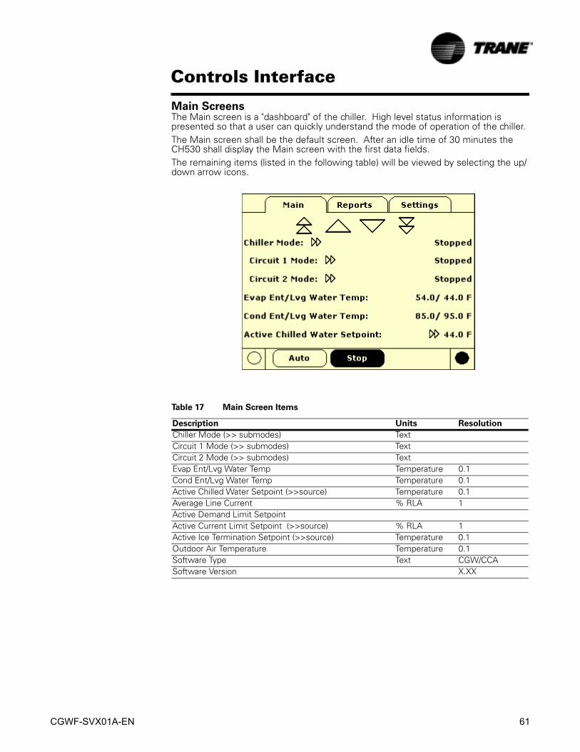
CGWF-SVX01A-EN 61
Controls Interface
Main ScreensThe Main screen is a "dashboard" of the chiller. High level status information is presented so that a user can quickly understand the mode of operation of the chiller.The Main screen shall be the default screen. After an idle time of 30 minutes the CH530 shall display the Main screen with the first data fields. The remaining items (listed in the following table) will be viewed by selecting the up/down arrow icons.
Table 17 Main Screen Items
Description Units Resolution
Chiller Mode (>> submodes) TextCircuit 1 Mode (>> submodes) TextCircuit 2 Mode (>> submodes) TextEvap Ent/Lvg Water Temp Temperature 0.1Cond Ent/Lvg Water Temp Temperature 0.1Active Chilled Water Setpoint (>>source) Temperature 0.1Average Line Current % RLA 1Active Demand Limit SetpointActive Current Limit Setpoint (>>source) % RLA 1Active Ice Termination Setpoint (>>source) Temperature 0.1Outdoor Air Temperature Temperature 0.1Software Type Text CGW/CCASoftware Version X.XX

62 CGWF-SVX01A-EN
Controls Interface
Table 18 Operating Modes
Chiller Level Mode Description
Top Level Mode DescriptionMP Resetting The main processor is going through reset.MP Resetting Sub Modes No Chiller Sub-ModesTop Level Mode DescriptionStopped The chiller is not running either circuit, and cannot run without intervention. Stopped Sub Modes DescriptionLocal Stop Chiller is stopped by the DynaView Stop button command- cannot be
remotely overridden.Immediate Stop Chiller is stopped by the DynaView Immediate Stop (by pressing the Stop
then Immediate Stop buttons in succession) - previous shutdown was manually commanded to shutdown immediately.
No Circuits Available The entire chiller is stopped by circuit diagnostics or lockouts that may automatically clear.
Diagnostic Shutdown - Manual Reset The chiller is stopped by a diagnostic that requires manual intervention to reset.
Top Level Mode DescriptionRun Inhibit The chiller is currently being inhibited from starting (and running), but may be
allowed to start if the inhibiting or diagnostic condition is cleared.Run Inhibit Sub Modes DescriptionIce Building Is Complete The chiller is inhibited from running as the Ice Building process has been
normally terminated on the evaporator entering temperature. The chiller will not start unless the ice building command (hardwired input or Building Automation System command) is removed or cycled.
Starting is Inhibited by Building Automation System
Chiller is stopped by Tracer or other BAS system.
Starting is Inhibited by External Source The chiller is inhibited from starting or running by the "external stop" hardwired input.
Diagnostic Shutdown - Auto Reset The entire chiller is stopped by a diagnostic that may automatically clear.Waiting for BAS Communications The chiller is inhibited because of lack of communication with the BAS. This
is only valid 15 minutes after power up.Starting is Inhibited by Low Ambient Temperature
The chiller is inhibited based on the outdoor air temperature.
Top Level Mode DescriptionAuto The chiller is not currently running but can be expected to start at any
moment given that the proper conditions and interlocks are satisfied. Auto Sub Modes DescriptionWaiting For Evaporator Water Flow The chiller will wait up to 20 minutes in this mode for evaporator water flow
to be established per the flow switch hardwired input.Waiting For A Need To Cool The chiller will wait indefinitely in this mode, for an evaporator leaving water
temperature higher than the Chilled Water Setpoint plus some control dead-band.
Power Up Delay Inhibit: MIN:SEC On Power up, the chiller will wait for the Power Up Delay Timer to expire.Top Level Mode DescriptionWaiting to Start The chiller is going through the necessary steps to allow the lead circuit to
start.Sub Modes DescriptionWaiting For Condenser Water Flow The chiller will wait up to 20 minutes in this mode for condenser water flow
to be established per the flow switch hardwired input.Top Level Mode DescriptionRunning At least one circuit on the chiller is currently running. Running Sub Modes DescriptionMaximum Capacity The chiller is operating at its maximum capacity.Capacity Control Softloading The control is limiting the chiller loading due to capacity based softloading
setpoints.
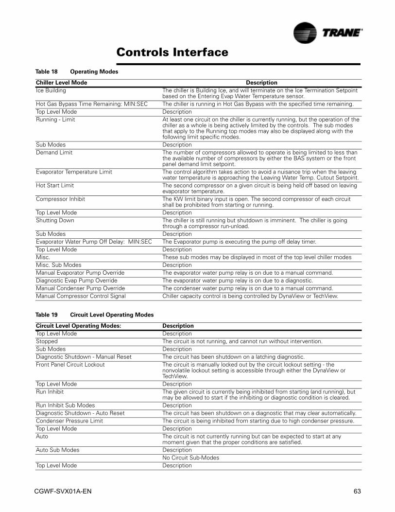
CGWF-SVX01A-EN 63
Controls Interface
Ice Building The chiller is Building Ice, and will terminate on the Ice Termination Setpoint based on the Entering Evap Water Temperature sensor.
Hot Gas Bypass Time Remaining: MIN:SEC The chiller is running in Hot Gas Bypass with the specified time remaining.Top Level Mode DescriptionRunning - Limit At least one circuit on the chiller is currently running, but the operation of the
chiller as a whole is being actively limited by the controls. The sub modes that apply to the Running top modes may also be displayed along with the following limit specific modes.
Sub Modes DescriptionDemand Limit The number of compressors allowed to operate is being limited to less than
the available number of compressors by either the BAS system or the front panel demand limit setpoint.
Evaporator Temperature Limit The control algorithm takes action to avoid a nuisance trip when the leaving water temperature is approaching the Leaving Water Temp. Cutout Setpoint.
Hot Start Limit The second compressor on a given circuit is being held off based on leaving evaporator temperature.
Compressor Inhibit The KW limit binary input is open. The second compressor of each circuit shall be prohibited from starting or running.
Top Level Mode DescriptionShutting Down The chiller is still running but shutdown is imminent. The chiller is going
through a compressor run-unload. Sub Modes DescriptionEvaporator Water Pump Off Delay: MIN:SEC The Evaporator pump is executing the pump off delay timer.Top Level Mode DescriptionMisc. These sub modes may be displayed in most of the top level chiller modesMisc. Sub Modes DescriptionManual Evaporator Pump Override The evaporator water pump relay is on due to a manual command.Diagnostic Evap Pump Override The evaporator water pump relay is on due to a diagnostic.Manual Condenser Pump Override The condenser water pump relay is on due to a manual command.Manual Compressor Control Signal Chiller capacity control is being controlled by DynaView or TechView.
Table 18 Operating Modes
Chiller Level Mode Description
Table 19 Circuit Level Operating Modes
Circuit Level Operating Modes: Description
Top Level Mode DescriptionStopped The circuit is not running, and cannot run without intervention.Sub Modes DescriptionDiagnostic Shutdown - Manual Reset The circuit has been shutdown on a latching diagnostic.Front Panel Circuit Lockout The circuit is manually locked out by the circuit lockout setting - the
nonvolatile lockout setting is accessible through either the DynaView or TechView.
Top Level Mode DescriptionRun Inhibit The given circuit is currently being inhibited from starting (and running), but
may be allowed to start if the inhibiting or diagnostic condition is cleared.Run Inhibit Sub Modes DescriptionDiagnostic Shutdown - Auto Reset The circuit has been shutdown on a diagnostic that may clear automatically.Condenser Pressure Limit The circuit is being inhibited from starting due to high condenser pressure.Top Level Mode DescriptionAuto The circuit is not currently running but can be expected to start at any
moment given that the proper conditions are satisfied.Auto Sub Modes Description
No Circuit Sub-ModesTop Level Mode Description

64 CGWF-SVX01A-EN
Controls Interface
Waiting to Start The chiller is going through the necessary steps to allow the lead circuit to start.
Sub Modes DescriptionNo Circuit Sub-Modes
Top Level Mode DescriptionRunning The compressor on the given circuit is currently running.Sub Modes Description
No Circuit Sub-ModesTop Level Mode DescriptionRunning - Limit The compressor on the given circuit is currently running in a limit mode.Sub Modes DescriptionLow Evaporator Pressure Start When LPC is open and either compressor on the circuit is running and the
LPC ignore time has not yet expired.Condenser Pressure Limit The circuit is being inhibited from loading due to high condenser pressure.Top Level Mode DescriptionPreparing Shutdown The circuit is preparing to de-energize the compressor.Preparing ShutdownSub Modes DescriptionOperational Pumpdown The operational pumpdown is enabled and the circuit is shutting down.Top Level Mode DescriptionShutting Down The chiller is going through the necessary steps after de-energizing the
compressor.Sub Modes Description
No Circuit Sub-ModesTop Level Mode DescriptionMisc. These sub modes may be displayed in most of the top level circuit modesMisc. Sub Modes DescriptionService Pumpdown The circuit is currently performing a service pumpdown.Compressor X Running A specific compressor is running where X is A or B.Restart Time Inhibit Cprsr X: MIN:SEC If there is accumulated Restart Inhibit Time, it must expire before the
compressor is allowed to start. X is denoted as compressor A or B.
Table 19 Circuit Level Operating Modes
Circuit Level Operating Modes: Description
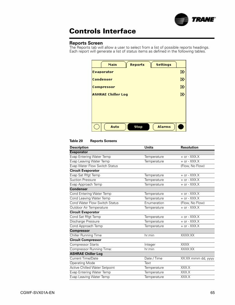
CGWF-SVX01A-EN 65
Controls Interface
Reports ScreenThe Reports tab will allow a user to select from a list of possible reports headings. Each report will generate a list of status items as defined in the following tables.
Table 20 Reports Screens
Description Units Resolution
Evaporator
Evap Entering Water Temp Temperature + or - XXX.XEvap Leaving Water Temp Temperature + or - XXX.XEvap Water Flow Switch Status (Flow, No Flow)Circuit Evaporator
Evap Sat Rfgt Temp Temperature + or - XXX.XSuction Pressure Temperature + or - XXX.XEvap Approach Temp Temperature + or - XXX.XCondenser
Cond Entering Water Temp Temperature + or - XXX.XCond Leaving Water Temp Temperature + or - XXX.XCond Water Flow Switch Status Enumeration (Flow, No Flow)Outdoor Air Temperature Temperature + or - XXX.XCircuit Evaporator
Cond Sat Rfgt Temp Temperature + or - XXX.XDischarge Pressure Temperature + or - XXX.XCond Approach Temp Temperature + or - XXX.XCompressor
Chiller Running Time hr:min XXXX:XXCircuit Compressor
Compressor Starts Integer XXXXCompressor Running Time: hr:min XXXX:XXASHRAE Chiller Log
Current Time/Date Date / Time XX:XX mmm dd, yyyyOperating Mode TextActive Chilled Water Setpoint Temperature XXX.XEvap Entering Water Temp Temperature XXX.XEvap Leaving Water Temp Temperature XXX.X
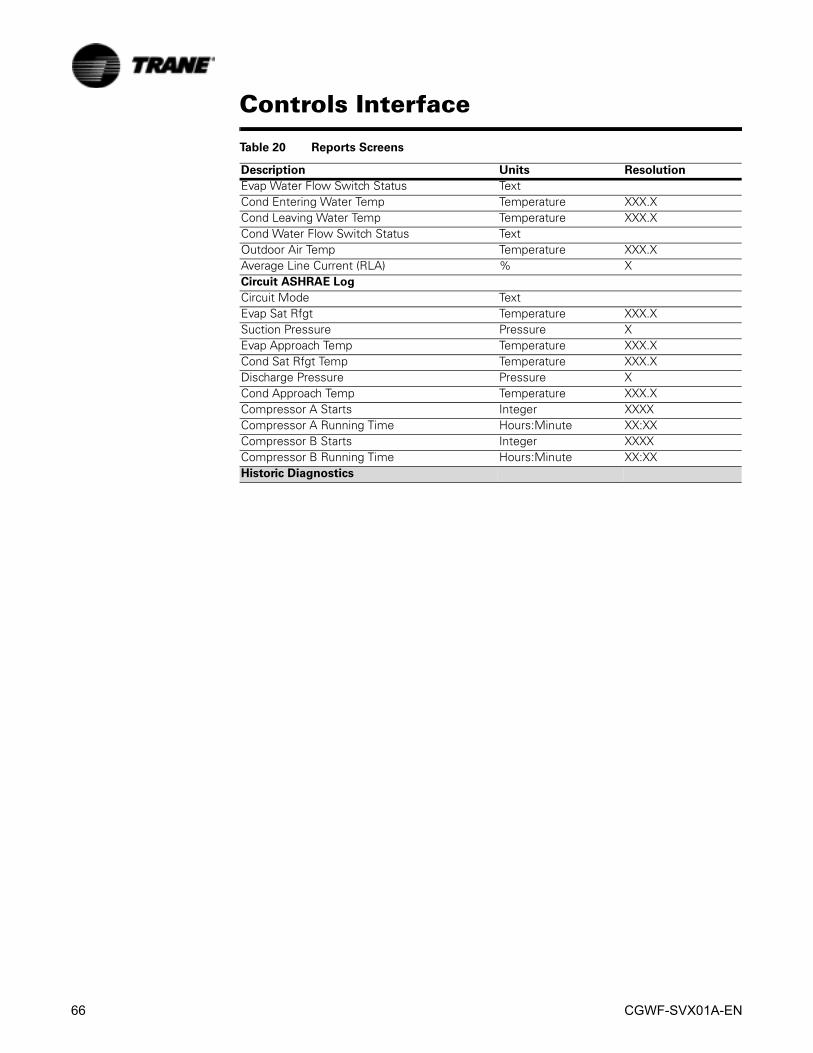
66 CGWF-SVX01A-EN
Controls Interface
Evap Water Flow Switch Status TextCond Entering Water Temp Temperature XXX.XCond Leaving Water Temp Temperature XXX.XCond Water Flow Switch Status TextOutdoor Air Temp Temperature XXX.XAverage Line Current (RLA) % XCircuit ASHRAE Log
Circuit Mode TextEvap Sat Rfgt Temperature XXX.XSuction Pressure Pressure XEvap Approach Temp Temperature XXX.XCond Sat Rfgt Temp Temperature XXX.XDischarge Pressure Pressure XCond Approach Temp Temperature XXX.XCompressor A Starts Integer XXXXCompressor A Running Time Hours:Minute XX:XXCompressor B Starts Integer XXXXCompressor B Running Time Hours:Minute XX:XXHistoric Diagnostics
Table 20 Reports Screens
Description Units Resolution

CGWF-SVX01A-EN 67
Controls Interface
Settings ScreenThe Settings screen provides a user the ability to adjust settings justified to support daily tasks. The layout provides a list of sub-menus, organized by typical subsystem. This organization allows each subscreen to be shorter in length which should improve the users navigation.
Table 21 Settings Screen
Description Units Resolution, Default
Chiller
Front Panel Chilled Water Setpt Temperature + or - XXX.XFront Panel Demand Limit XFront Panel Ice Build Cmd Text On/AutoFront Panel Ice Termn Setpt Temperature XXX.XDesign Delta Temp Temperature XXX.XSetpoint Source Text (BAS/Ext/FP, Ext/ Front Panel,
Front Panel), BAS/Ext/FPLeaving Water Temp Cutout Temperature XX.XFeature Settings
Low Ambient Lockout Setpoint (CCAF) Temperature XXX.XLow Ambient Lockout (CCAF) Text (Enable, Disable), EnableChilled Water Reset Text (Constant, Outdoor, Return,
Disable), DisableReturn Reset Ratio Percent XXXReturn Start Reset Temperature XXX.XReturn Maximum Reset Temperature XXX.XOutdoor Reset Ratio Percent XXXOutdoor Start Reset Temperature XXX.XOutdoor Maximum Reset Temperature XXX.XExt Chilled Water Setpoint Text (Enable, Disable), DisableIce Building Text (Enable, Disable), DisableHot Gas Bypass Text (Enable, Disable), DisableOperational Pumpdown Text (Enable, Disable), DisableICS Address Text XX
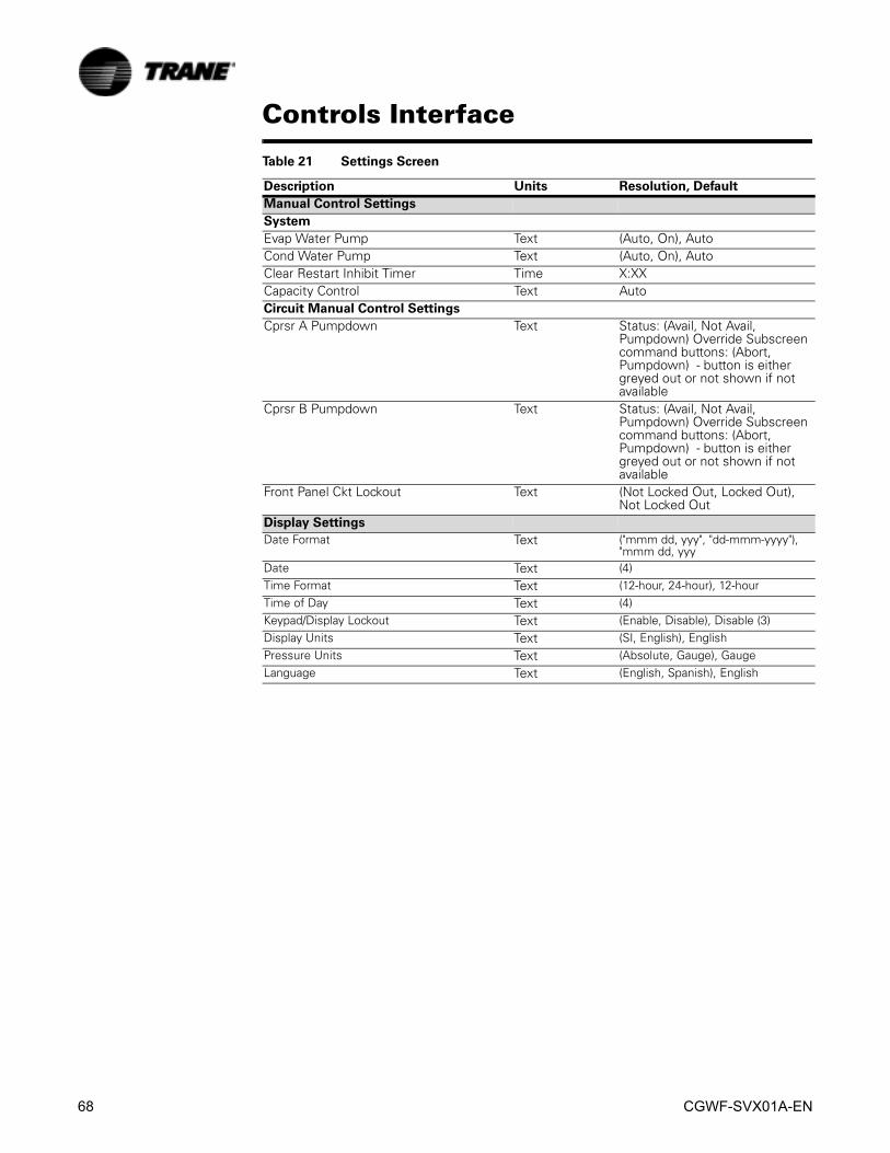
68 CGWF-SVX01A-EN
Controls Interface
Manual Control Settings
System
Evap Water Pump Text (Auto, On), Auto Cond Water Pump Text (Auto, On), Auto Clear Restart Inhibit Timer Time X:XXCapacity Control Text AutoCircuit Manual Control Settings
Cprsr A Pumpdown Text Status: (Avail, Not Avail, Pumpdown) Override Subscreen command buttons: (Abort, Pumpdown) - button is either greyed out or not shown if not available
Cprsr B Pumpdown Text Status: (Avail, Not Avail, Pumpdown) Override Subscreen command buttons: (Abort, Pumpdown) - button is either greyed out or not shown if not available
Front Panel Ckt Lockout Text (Not Locked Out, Locked Out), Not Locked Out
Display Settings
Date Format Text ("mmm dd, yyy", "dd-mmm-yyyy"), "mmm dd, yyy
Date Text (4)Time Format Text (12-hour, 24-hour), 12-hourTime of Day Text (4)Keypad/Display Lockout Text (Enable, Disable), Disable (3)Display Units Text (SI, English), EnglishPressure Units Text (Absolute, Gauge), GaugeLanguage Text (English, Spanish), English
Table 21 Settings Screen
Description Units Resolution, Default

CGWF-SVX01A-EN 69
Controls Interface
Diagnostics ScreenThe diagnostic screen is accessible by depressing the Alarms enunciatorA scrollable list of the last (up to 20) active diagnostics will be presented. Performing a Reset All Active Diagnostics will reset all active diagnostics regardless of type, machine or refrigerant circuit. Compressor diagnostics, which hold off only one compressor, will be treated as circuit diagnostics, consistent with the circuit to which they belong. The scrollable list will be sorted by time of occurrence.If a diagnostic of severity = warning is present, the "Alarms" key will be present but not flashing. If a diagnostic of severity = shutdown (normal or immediate) is present, the "Alarm" key will display that is flashing. If no diagnostics exist, the "Alarm" key will not be present.The "Operating Mode At Last Diagnostic" text above the most recent diagnostic will display a sub-screen listing the operating mode and submodes at the time of the last diagnostic.
TechView InterfaceTechView is the PC (laptop) based tool used for servicing Tracer CH530. Technicians that make any chiller control modification or service any diagnostic with Tracer CH530 must use a laptop running the software application “TechView.” TechView is a Trane application developed to minimize chiller downtime and aid the technicians' understanding of chiller operation and service requirements.
NOTE: Important: Performing any Tracer CH530 service functions should be done only by a properly trained service technician. Please contact your local Trane service agency for assistance with any service requirements.
TechView software is available via Trane.com.(http://www.trane.com/commercial/software/tracerch530/) This download site provides a user the TechView installation software and CH530 main processor software that must be loaded onto your PC in order to service a CH530 main processor. The TechView service tool is used to load software into the Tracer CH530 main processor.Minimum PC requirements to install and operate TechView are:• Pentium II or higher processor
• 128Mb RAM
• 1024 x 768 resolution of display
70 CGWF-SVX01A-EN
Controls Interface
• CD-ROM
• 56K modem
• 9-pin RS-232 serial connection
• Operating system - Windows 2000
• Microsoft Office (MS Word, MS Access, MS Excel)
• Parallel Port (25-pin) or USB Port
NOTE: TechView was designed for the preceding listed laptop configuration. Any variation will have unknown results. Therefore, support for TechView is limited to only those operating systems that meet the specific configuration listed here. Only computers with a Pentium II class processor or better are supported; Intel Celeron, AMD, or Cyrix processors are not supported.
TechView is also used to perform any CH530 service or maintenance function. Servicing a CH530 main processor includes: • Updating main processor software
• Monitoring chiller operation
• Viewing and resetting chiller diagnostics
• Low Level Intelligent Device (LLID) replacement and binding
• Main processor replacement and configuration modifications
• Setpoint modifications
• Service overrides
Software Download
Instructions for First Time TechView UsersThis information can also be found at http://www.trane.com/commercial/software/tracerch530/.1. Create a folder called “CH530” on your C:\ drive. You will select and use this
folder in subsequent steps so that downloaded files are easy to locate.
2. Download the Java Runtime installation utility file onto your PC in the CH530 folder (please note that this does not install Java Runtime, it only downloads the installation utility).
– Click on the latest version of Java Runtime shown in the TechView Download table.
– Select “Save this program to disk” while downloading the files (do not select “Run this program from its current location”).
3. Download the TechView installation utility file onto your PC in the CH530 folder (please note that this does not install TechView, it only downloads the installation utility).
– Click on the latest version of TechView shown in the TechView Download table. – Select “Save this program to disk” while downloading the files (do not select
“Run this program from its current location”). 4. Remember where you downloaded the files (the “CH530” folder). You will need
to locate them to finish the installation process.
5. Proceed to “Main Processor Software Download” page and read the instructions to download the latest version of main processor installation files.
Note: you will first select the chiller type to obtain the available file versions.
CGWF-SVX01A-EN 71
Controls Interface6. Select the product family. A table with the download link will appear for that prod-
uct family.
7. Download the main processor software onto your PC in the CH530 folder (please note that this does not install the main processor, it only downloads the installa-tion utility).
– To do this, click on the latest version of the main processor. – Select “Save this program to disk” while downloading the files (do not select
“Run this program from its current location”). 8. Remember where you downloaded the files (the “CH530” folder). You will need
to locate them to finish the installation process.
9. To complete the installation process, locate the installation utilities you down-loaded into the CH530 folder. If necessary, use your PC’s file manager to locate the downloaded files.
10. Install the applications in the following order by double-clicking on the install pro-gram and following the installation prompts:
– Java Runtime Environment (JRE_VXXX.exe) Note: During the Java Runtime Environment installation, you may be prompted to “select the default Java Runtime for the system browsers...”. Do not select any system browsers at this step. There should be no default browsers selected for proper operation.
– TechView (6200-0347-VXXX.exe) – The main processor (6200-XXXX-XX-XX.exe). – The main processor program will self extract to the proper folder within the
TechView program directory, provided the TechView program is properly installed on the C:\ drive.
11. Connect your PC to the CH530 main processor using a standard 9-pin male/9-pin female RS-232 cable.
12. Run the TechView software by selecting the TechView icon placed on your desk-top during the installation process. The “Help...About” menu can be viewed to confirm proper installation of latest versions.

72 CGWF-SVX01A-EN
Controls Interface
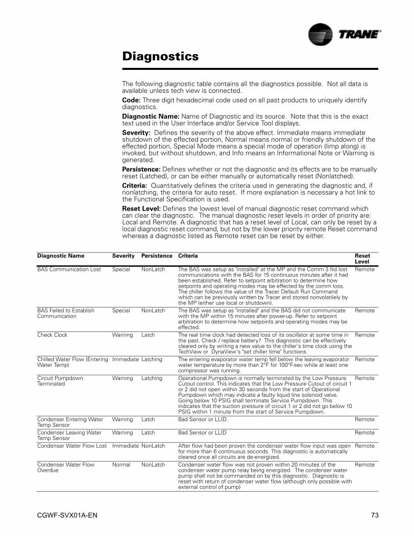
CGWF-SVX01A-EN 73
Diagnostics
The following diagnostic table contains all the diagnostics possible. Not all data is available unless tech view is connected.Code: Three digit hexadecimal code used on all past products to uniquely identify diagnostics. Diagnostic Name: Name of Diagnostic and its source. Note that this is the exact text used in the User Interface and/or Service Tool displays.Severity: Defines the severity of the above effect. Immediate means immediate shutdown of the effected portion, Normal means normal or friendly shutdown of the effected portion, Special Mode means a special mode of operation (limp along) is invoked, but without shutdown, and Info means an Informational Note or Warning is generated.Persistence: Defines whether or not the diagnostic and its effects are to be manually reset (Latched), or can be either manually or automatically reset (Nonlatched).Criteria: Quantitatively defines the criteria used in generating the diagnostic and, if nonlatching, the criteria for auto reset. If more explanation is necessary a hot link to the Functional Specification is used.Reset Level: Defines the lowest level of manual diagnostic reset command which can clear the diagnostic. The manual diagnostic reset levels in order of priority are: Local and Remote. A diagnostic that has a reset level of Local, can only be reset by a local diagnostic reset command, but not by the lower priority remote Reset command whereas a diagnostic listed as Remote reset can be reset by either.
Diagnostic Name Severity Persistence Criteria Reset Level
BAS Communication Lost Special NonLatch The BAS was setup as "installed" at the MP and the Comm 3 llid lost communications with the BAS for 15 continuous minutes after it had been established. Refer to setpoint arbitration to determine how setpoints and operating modes may be effected by the comm loss. The chiller follows the value of the Tracer Default Run Command which can be previously written by Tracer and stored nonvolatilely by the MP (either use local or shutdown).
Remote
BAS Failed to Establish Communication
Special NonLatch The BAS was setup as "installed" and the BAS did not communicate with the MP within 15 minutes after power-up. Refer to setpoint arbitration to determine how setpoints and operating modes may be effected.
Remote
Check Clock Warning Latch The real time clock had detected loss of its oscillator at some time in the past. Check / replace battery? This diagnostic can be effectively cleared only by writing a new value to the chiller's time clock using the TechView or DynaView's "set chiller time" functions.
Remote
Chilled Water Flow (Entering Water Temp)
Immediate Latching The entering evaporator water temp fell below the leaving evaporator water temperature by more than 2°F for 100°F-sec while at least one compressor was running.
Remote
Circuit Pumpdown Terminated
Warning Latching Operational Pumpdown is normally terminated by the Low Pressure Cutout control. This indicates that the Low Pressure Cutout of circuit 1 or 2 did not open within 30 seconds from the start of Operational Pumpdown which may indicate a faulty liquid line solenoid valve. Going below 10 PSIG shall terminate Service Pumpdown. This indicates that the suction pressure of circuit 1 or 2 did not go below 10 PSIG within 1 minute from the start of Service Pumpdown.
Remote
Condenser Entering Water Temp Sensor
Warning Latch Bad Sensor or LLID. Remote
Condenser Leaving Water Temp Sensor
Warning Latch Bad Sensor or LLID Remote
Condenser Water Flow Lost Immediate NonLatch After flow had been proven the condenser water flow input was open for more than 6 continuous seconds. This diagnostic is automatically cleared once all circuits are de-energized.
Remote
Condenser Water Flow Overdue
Normal NonLatch Condenser water flow was not proven within 20 minutes of the condenser water pump relay being energized. The condenser water pump shall not be commanded on by this diagnostic. Diagnostic is reset with return of condenser water flow (although only possible with external control of pump)
Remote

74 CGWF-SVX01A-EN
Diagnostics
Current L1 Loss Immediate Latch No current was sensed on the current transformer L1 input while starting or running. Time to trip shall be longer than guaranteed reset on Starter Module at a minimum, 3 seconds maximum. Actual design trip point is 10%. The actual design trip time is 2.64 seconds. If Phase reversal protection is enabled and current is not sensed on one or more current xformer inputs. Logic will detect and trip in a maximum of 0.3 second from compressor start.
Local
Current L2 Loss Immediate Latch Same as Current L1 Loss except L2 input. LocalCurrent L3 Loss Immediate Latch Same as Current L1 Loss except L3 input. LocalDischarge Pressure Transducer
Normal Latch Bad Sensor or LLID Remote
Emergency Stop Immediate Latch Emergency Stop input is open. LocalEvaporator Entering Water Temp Sensor
Normal Latch Bad Sensor or LLID. Remote
Evaporator Leaving Water Temp Sensor
Normal Latch Bad Sensor or LLID Remote
Evaporator Water Flow Lost Immediate NonLatch After flow had been proven the chilled water flow input was open for more than 6 continuous seconds. The evaporator pump shall be commanded on until the diagnostic clears even if the chiller is in STOP. 6-10 seconds of continuous flow shall clear this diagnostic. Some customers use the pump to control the chiller.
Remote
Evaporator Water Flow Overdue
Immediate NonLatch Evaporator water flow was not proven within 20 minutes of the evaporator water pump relay being energized. The evaporator water pump relay will remain energized to support installations where the evaporator water pump is turned off to shut down the chiller. Diagnostic is reset with return of evaporator water flow.
Remote
External Chilled Water Setpoint
Warning NonLatch a. Function Not "Enabled": no diagnostics. b. "Enabled ": Out-Of-Range Low or Hi or bad LLID, set diagnostic, default CWS to next level of priority (e.g. Front Panel SetPoint). This Warning diagnostic will automatically reset if the input returns to the normal range.
Remote
High Evaporator Water Temperature
Immediate NonLatch The evaporator leaving water temperature is above 115°F. This diagnostic shall clear once the evaporator leaving water temperature falls below 110°F. This diagnostic protects the rupture disk and plastic baffles in the evaporator. The evaporator water pump shall not run when this diagnostic is active.
Local
High Motor Temp/Overload Trip Cprsr A
Immediate Latch The High Motor Temperature or the Compressor Overload switch input is open for compressor A.
Local
High Motor Temp/Overload Trip Cprsr B
Immediate Latch The High Motor Temperature or the Compressor Overload switch input is open for compressor B.
Local
High Pressure Cutout Immediate Latch The high pressure cutout switch was open for more than three seconds. The high pressure cutout switch for R22 used on this machine is an open at 405 PSIG and a close at 300 PSIG.
Local
Low Evap Leaving Water Temp: Unit Off
Warning and Special Action
NonLatch The leaving chilled water temperature fell below the leaving water temp cutout setting for 30 degree F seconds while the Chiller is in the Stop mode, or in Auto mode with no compressors running. Energize Evap Water pump Relay until diagnostic auto resets, then return to normal evap pump control. Automatic reset occurs when the temp rises 2°F above the cutout setting for 30 minutes. When this diagnostic is active AND Leaving Water Temperature sensor diagnostic (loss of comm or out of range) the Evap Water pump relay shall be de-energized.
Remote
Low Evap Leaving Water Temp: Unit On
Immediate and Special Action
NonLatch The chilled water temp. fell below the cutout setpoint for 30 degree F Seconds while the compressor was running. Automatic reset occurs when the temperature rises 2 °F above the cutout setting for 2 minutes. This diagnostic shall not de-energize the Evaporator Water Pump Output. If this diagnostic is active the Low Evap Leaving Water Temp: Unit Off diagnostic shall be suppressed.
Remote
Low Pressure Cutout Immediate Latch · The low suction refrigerant pressure diagnostic occurred more than five times during a given demand period or failed to reset in 60 seconds after opening when either compressor A or B were running and the unit was not in a Service Pumpdown or Operational Pumpdown.
Local
Low Suction Refrigerant Pressure
Immediate NonLatch The pressure status, described in the Low Suction Refrigerant Pressure Protection specification, was opened. This diagnostic will clear when the status goes closed.
Local
Diagnostic Name Severity Persistence Criteria Reset Level

CGWF-SVX01A-EN 75
Diagnostics
MP: Could not Store Starts and Hours
Warning Latch MP has determined there was an error with the previous power down store. Starts and Hours may have been lost for the last 24 hours.
Remote
MP: Non-Volatile Block Test Error
Warning Latch MP has determined there was an error with a block in the Non-Volatile memory. Check settings.
MP: Non-Volatile Memory Reformat
Warning Latch MP has determined there was an error in a sector of the Non-Volatile memory and it was reformatted. Check settings.
Remote
MP: Reset Has Occurred Warning NonLatch The main processor has successfully come out of a reset and built its application. A reset may have been due to a power up, installing new software or configuration. This diagnostic is immediately and automatically cleared and thus can only be seen in the historic diagnostic list.
NA
Outdoor Air Temp Sensor Warning and Special Action
Latch Bad Sensor or LLID. If configured as a CCA this diagnostic shall turn on all fans and use a minimum LPC ignore time of 30 seconds.
Remote
Phase Reversal Immediate Latch A phase reversal was detected on the incoming current. LocalPower Loss Immediate NonLatch The compressor had previously established currents while running and
then all three phases of current were lost. Design: Less than 10% RLA, trip in 2.64 seconds. This diagnostic will preclude the Phase Loss Diagnostic from being called out. To prevent this diagnostic from occurring with the intended disconnect of main power, the minimum time to trip must be greater than the guaranteed reset time of the Starter module. This diagnostic will auto reset in 10 seconds from its occurrence, and is not active during the start mode.
Remote
Starter Contactor Interrupt Failure
Immediate and Special Action
Latch Detected a maximum chiller current greater than 10% RLA on any or all phases when all compressors were commanded off. Detection time shall be 10 seconds maximum. On detection and until the controller is manually reset: generate diagnostic and energize the appropriate alarm relay. Anytime the condition is present energize the liquid line solenoid valves, continue to energize the Evaporator Pump and Condenser Pump if CGWF or if CCAF energize the Condenser Fans according to the fan staging algorithm.
Local
Starter Module Memory Error Type 2
Immediate Shutdown
Latching Checksum on EEPROM copy of the Starter LLID configuration failed. Factor default values used.
Local
Starts/Hours Modified - Compressor X
Warning NonLatch A counter for compressor starts or hours has been modified by TechView. The diagnostic shall indicate compressor A or B. This diagnostic is immediately and automatically cleared and thus can only be seen in the historic diagnostic list.
NA
Suction Pressure Transducer Immediate Latch Bad Sensor or LLID RemoteExcessive Loss of Comm Immediate Latch Loss of comm with 20% or more of the llids configured for the system
has been detected. This diagnostic will suppress the call out of all subsequent comm loss diagnostics. Check power supply(s) and power disconnects - troubleshoot LLIDS buss using TechView
Remote
Comm Loss: External Auto/Stop
Normal Latch Continual loss of communication between the MP and the Functional ID has occurred for a 35-40 second period.
Remote
Comm Loss: Emergency Stop
Normal Latch Continual loss of communication between the MP and the Functional ID has occurred for a 35-40 second period.
Remote
Comm Loss: Ext Ice Building Ctrl Input
Warning Latch Continual loss of communication between the MP and the Functional ID has occurred for a 35-40 second period. Chiller shall revert to normal (non-ice building) mode regardless of last state.
Remote
Comm Loss: Outdoor Air Temperature
Warning Latch Continual loss of communication between the MP and the Functional ID has occurred for a 35-40 second period. If configured as a CCA this diagnostic shall turn on all fans and use a minimum LPC ignore time of 30 seconds.
Remote
Comm Loss: Evap Leaving Water Temp
Normal Latch Continual loss of communication between the MP and the Functional ID has occurred for a 35-40 second period.
Remote
Comm Loss: Evap Entering Water Temp
Normal Latch Continual loss of communication between the MP and the Functional ID has occurred for a 35-40 second period.
Remote
Comm Loss: Condenser Leaving Water Temp
Warning Latch Continual loss of communication between the MP and the Functional ID has occurred for a 35-40 second period.
Remote
Comm Loss: Condenser Entering Water Temp
Warning Latch Continual loss of communication between the MP and the Functional ID has occurred for a 35-40 second period.
Remote
Comm Loss: Discharge Pressure Transducer
Normal Latch Continual loss of communication between the MP and the Functional ID has occurred for a 35-40 second period.
Remote
Diagnostic Name Severity Persistence Criteria Reset Level
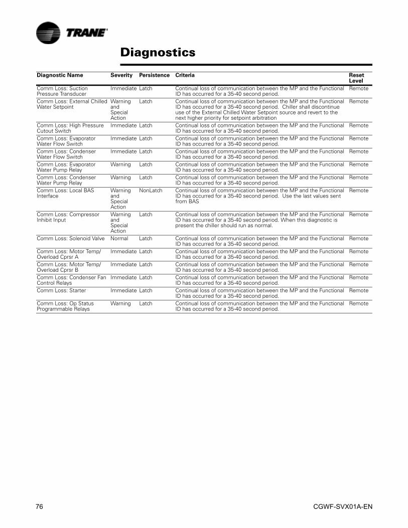
76 CGWF-SVX01A-EN
Diagnostics
Comm Loss: Suction Pressure Transducer
Immediate Latch Continual loss of communication between the MP and the Functional ID has occurred for a 35-40 second period.
Remote
Comm Loss: External Chilled Water Setpoint
Warning and Special Action
Latch Continual loss of communication between the MP and the Functional ID has occurred for a 35-40 second period. Chiller shall discontinue use of the External Chilled Water Setpoint source and revert to the next higher priority for setpoint arbitration
Remote
Comm Loss: High Pressure Cutout Switch
Immediate Latch Continual loss of communication between the MP and the Functional ID has occurred for a 35-40 second period.
Remote
Comm Loss: Evaporator Water Flow Switch
Immediate Latch Continual loss of communication between the MP and the Functional ID has occurred for a 35-40 second period.
Remote
Comm Loss: Condenser Water Flow Switch
Immediate Latch Continual loss of communication between the MP and the Functional ID has occurred for a 35-40 second period.
Remote
Comm Loss: Evaporator Water Pump Relay
Warning Latch Continual loss of communication between the MP and the Functional ID has occurred for a 35-40 second period.
Remote
Comm Loss: Condenser Water Pump Relay
Warning Latch Continual loss of communication between the MP and the Functional ID has occurred for a 35-40 second period.
Remote
Comm Loss: Local BAS Interface
Warning and Special Action
NonLatch Continual loss of communication between the MP and the Functional ID has occurred for a 35-40 second period. Use the last values sent from BAS
Remote
Comm Loss: Compressor Inhibit Input
Warning and Special Action
Latch Continual loss of communication between the MP and the Functional ID has occurred for a 35-40 second period. When this diagnostic is present the chiller should run as normal.
Remote
Comm Loss: Solenoid Valve Normal Latch Continual loss of communication between the MP and the Functional ID has occurred for a 35-40 second period.
Remote
Comm Loss: Motor Temp/Overload Cprsr A
Immediate Latch Continual loss of communication between the MP and the Functional ID has occurred for a 35-40 second period.
Remote
Comm Loss: Motor Temp/Overload Cprsr B
Immediate Latch Continual loss of communication between the MP and the Functional ID has occurred for a 35-40 second period.
Remote
Comm Loss: Condenser Fan Control Relays
Immediate Latch Continual loss of communication between the MP and the Functional ID has occurred for a 35-40 second period.
Remote
Comm Loss: Starter Immediate Latch Continual loss of communication between the MP and the Functional ID has occurred for a 35-40 second period.
Remote
Comm Loss: Op Status Programmable Relays
Warning Latch Continual loss of communication between the MP and the Functional ID has occurred for a 35-40 second period.
Remote
Diagnostic Name Severity Persistence Criteria Reset Level
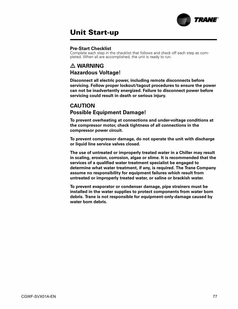
CGWF-SVX01A-EN 77
Unit Start-up
Pre-Start ChecklistComplete each step in the checklist that follows and check off each step as com-pleted. When all are accomplished, the unit is ready to run.
� WARNING
Hazardous Voltage!
Disconnect all electric power, including remote disconnects before
servicing. Follow proper lockout/tagout procedures to ensure the power
can not be inadvertently energized. Failure to disconnect power before
servicing could result in death or serious injury.
CAUTION
Possible Equipment Damage!
To prevent overheating at connections and under-voltage conditions at
the compressor motor, check tightness of all connections in the
compressor power circuit.
To prevent compressor damage, do not operate the unit with discharge
or liquid line service valves closed.
The use of untreated or improperly treated water in a Chiller may result
in scaling, erosion, corrosion, algae or slime. It is recommended that the
services of a qualified water treatment specialist be engaged to
determine what water treatment, if any, is required. The Trane Company
assume no responsibility for equipment failures which result from
untreated or improperly treated water, or saline or brackish water.
To prevent evaporator or condenser damage, pipe strainers must be
installed in the water supplies to protect components from water born
debris. Trane is not responsible for equipment-only-damage caused by
water born debris.
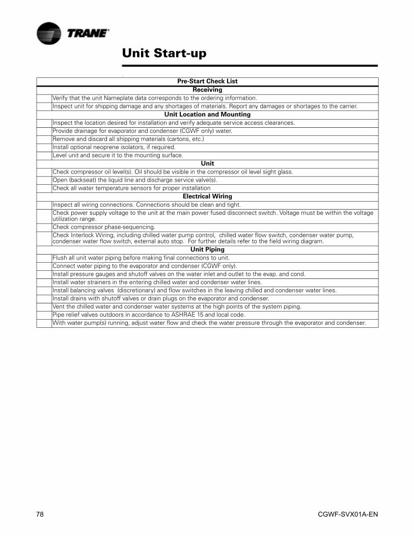
78 CGWF-SVX01A-EN
Unit Start-up
.
Pre-Start Check List
Receiving
Verify that the unit Nameplate data corresponds to the ordering information.Inspect unit for shipping damage and any shortages of materials. Report any damages or shortages to the carrier.
Unit Location and Mounting
Inspect the location desired for installation and verify adequate service access clearances.Provide drainage for evaporator and condenser (CGWF only) water.Remove and discard all shipping materials (cartons, etc.)Install optional neoprene isolators, if required. Level unit and secure it to the mounting surface.
Unit
Check compressor oil level(s). Oil should be visible in the compressor oil level sight glass.Open (backseat) the liquid line and discharge service valve(s).Check all water temperature sensors for proper installation
Electrical Wiring
Inspect all wiring connections. Connections should be clean and tight.Check power supply voltage to the unit at the main power fused disconnect switch. Voltage must be within the voltage utilization range.Check compressor phase-sequencing.Check Interlock Wiring, including chilled water pump control, chilled water flow switch, condenser water pump, condenser water flow switch, external auto stop. For further details refer to the field wiring diagram.
Unit Piping
Flush all unit water piping before making final connections to unit.Connect water piping to the evaporator and condenser (CGWF only).Install pressure gauges and shutoff valves on the water inlet and outlet to the evap. and cond.Install water strainers in the entering chilled water and condenser water lines.Install balancing valves (discretionary) and flow switches in the leaving chilled and condenser water lines.Install drains with shutoff valves or drain plugs on the evaporator and condenser.Vent the chilled water and condenser water systems at the high points of the system piping.Pipe relief valves outdoors in accordance to ASHRAE 15 and local code.With water pump(s) running, adjust water flow and check the water pressure through the evaporator and condenser.

CGWF-SVX01A-EN 79
Unit Start-up
Unit Power Up
Checking Operating Conditions Once the unit has been operating for about 10 minutes and the system has stabilized, check operating conditions and complete the checkout procedures that follow. • Recheck evaporator water and condenser (CGWF) water flows and pressure
drops. These readings should be stable at proper levels.
• Check suction pressure and discharge pressure of the unit.
Discharge pressures - take at discharge line service valve backseat port. Normal dis-charge pressures are:
CCAF units 200 to 360 psig CGWF units 175 to 275 psig
Suction pressures - take at Schraeder fitting provided on the suction line. Normal suc-tion pressures are:
40-60 F LWT = 50-85 psig 15-39 F LWT = 25-50 psig.
• Check compressor oil levels. At full load, oil level should be visible in the oil level sight glass on the compressor. If it is not, add or remove oil as required.
• Check the liquid line sight glasses. Refrigerant flow past the sight glasses should be clear. Bubbles in the liquid line indicate either low refrigerant charge or exces-sive pressure drop in the liquid line. Such a restriction can often be identified by a noticeable temperature differential on either side of the restricted area. Frost often forms on the outside of the liquid line at this point also.
Figure 23 Unit Power UP
Enforce RestartInhibit Timer
ChillerLevel
Power Appliedto CH530
LeadCircuit
RunningAuto
LagCircuit
Auto(Power
Up StartDelay)
Auto
EnergizeEvaporator WaterPump Relay
Running
EnergizeCondenser WaterPump Relay
Call for Cooling
Confirm EvaporatorWater Flow
Confirm CondenserWater Flow
EnergizeCprsr A
Auto Waiting toStart
Auto Auto
Open Liquid LineSolenoid Valve
(6 to 1200 Sec) (6 to 1200 Sec)
(0 to 5 Mins)
CH530 Boot Time
(24 to 42 Sec)
Enforce Power UpStart Delay Time
(0 to 600 Sec)
Auto

80 CGWF-SVX01A-EN
Unit Start-up
The system may not be properly charged although the sight glass is clear. Also consider superheat, subcooling and operating pressures.
• Once oil level, amp draw and operating pressures have stabilized, measure sys-tem suction superheat.
• Measure system liquid line subcooling.
• If operating pressure, sight glass, superheat and subcooling readings indicate refrigerant shortage, gas-charge refrigerant into each circuit. Refrigerant shortage is indicated if operating pressures are low and subcooling is also low.
If suction and discharge pressures are low but subcooling is normal, no refriger-ant shortage exists. Adding refrigerant, will result in overcharging.
Add refrigerant with the unit running by charging through the Schraeder valve between the expansion valve and the evaporator refrigerant inlet until operating condi-tions are normal.
CAUTION
Compressor Damage!
To prevent compressor damage, do not allow liquid refrigerant to enter
the suction line.
To prevent compressor damage and insure full cooling capacity, use
refrigerants specified on the unit nameplate only.
• If operating conditions indicate an overcharge, slowly (to minimize oil loss) remove refrigerant at the liquid line service valve. Do not discharge refrigerant into the atmosphere.
• If the unit is equipped with hot gas bypass, check regulating and solenoid valve for proper operation. Valve operating setpoints for 44-45 F evaporator leaving water temperature are:
Full open @ 61 psig,
Full closed @ 69 psig For other conditions, adjust the valve so that it is full open at normal suction pressure when the unit is operating at minimum cooling level. • If the remote condenser (CCAF) is equipped with low ambient dampers, check for
proper actuator and blade travel in relation to condensing pressure. Damper oper-ating setpoints are:
170 psig = Dampers fully closed; 250 psig = Dampers fully open.
• Once proper unit operation is confirmed, inspect for debris, misplaced tools., etc. Secure control panel doors in place.
System Superheat Normal superheat for each circuit is 10-12 F at full load. If superheat is not within this range, adjust expansion valve superheat setting. Allow 5-10 minutes between adjust-ments for the expansion valve to stabilize on each new setting.
System Subcooling Normal subcooling for each circuit is 10 to 15 F at full load. If subcooling for either cir-cuit is not in this range check superheat for the circuit and adjust, if required. If super-heat is normal but subcooling is not, contact a qualified service technician.

CGWF-SVX01A-EN 81
Unit Shutdown
Normal Unit Shutdown
Extended Shutdown Procedure If the system is taken out of operation for long periods of time, use this procedure to prepare the system for shutdown. 1. Perform "Manual Pumpdown" procedure described in this section. Be certain to
perform this procedure for both circuits.
2. Test condenser and high side piping for refrigerant leakage.
3. Open electrical disconnect switches for evaporator water pump. Lock the discon-nect in open position.
4. Open the unit main electrical disconnect and unit-mounted disconnect 1S1 (if used) and lock in open position.
Figure 24 Normal Unit Shutdown
EnergizeCprsr B
( p p )
ChillerLevel
LeadCircuit
LagCircuit
Stoppedor RunInhibit
De-EnergizeCprsr B
Shutting Down(Operational Pumpdown)
De-EnergizeCprsr A
De- EnergizeCprsr B
Auto
Running
De-EnergizeCprsr A
Close Liquid LineSolenoid Valve
30 Seconds or Low Suction Rfgt Pressure
De-Energize CondenserWater Pump Relay
Shutting Down(Operational Pumpdown)
Local StopNormal Latching DiagnosticChiller Level Non-Latching Diagnostic
Tracer StopExternal Auto-Stop
Run Inhibit
Stopped
30 Seconds or Low Suction Rfgt Pressure
Close Liquid LineSolenoid Valve
Evap Pump Off Delay Timer
(0 to 30 Minutes)
De-Energize EvaporatorWater Pump Relay
Shutting Down
Auto

82 CGWF-SVX01A-EN
Unit Shutdown
CAUTION
Equipment Damage!
Lock evaporator water pump disconnect open to prevent pump damage.
If unit water vessels are exposed to sub-freezing ambient temperatures,
take precautions to prevent unit damage.
Lock unit main disconnect open to prevent compressor damage due to
accidental start-up while system is in "shutdown" condition.
System Restart After Extended Shutdown Use this procedure to prepare the system for restart after an extended shutdown.
CAUTION
Compressor Damage!
To prevent compressor damage, be certain that all refrigerant valves are
open before starting the unit.
1. Open (backseat) the liquid line and discharge line service valve(s).
2. Close the unit main disconnect and the unit-mounted disconnect (if used).
3. Check compressor crankcase oil levels. Oil should be visible in the compressor oil level sight glass.
4. Fill the chilled water circuit(s) if drained during shutdown. Vent the system while filling it.
5. Close the fused disconnect switch(es) for the water pumps.
6. Start the water pump(s). With water pumps running, inspect all piping connec-tions for leakage. Make any necessary repairs.
7. With water pump(s) running, adjust chilled water flow and check water pressure drop through the evaporator.
8. Check the flow switch on the evaporator outlet piping for proper operation.
9. Stop the water pump(s).
10. Proceed to "Start-Up Procedure".
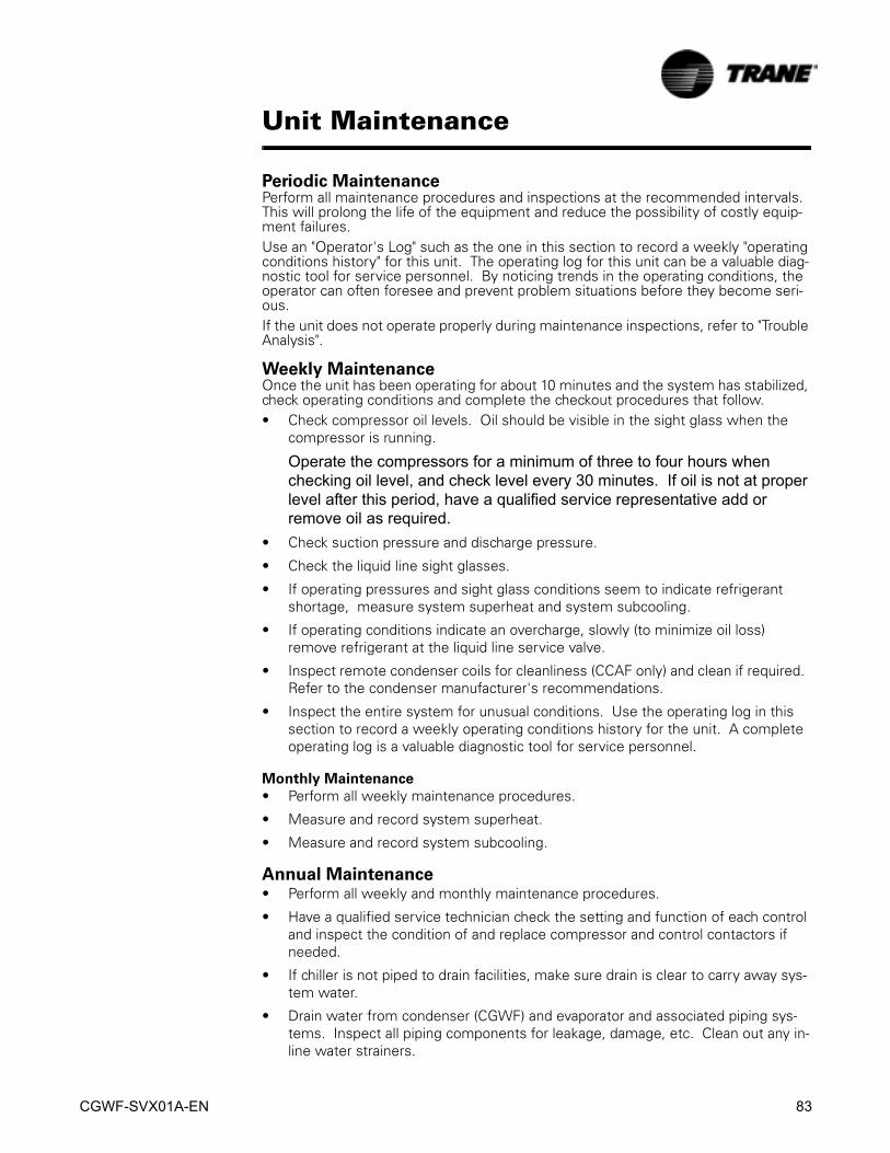
CGWF-SVX01A-EN 83
Unit Maintenance
Periodic MaintenancePerform all maintenance procedures and inspections at the recommended intervals. This will prolong the life of the equipment and reduce the possibility of costly equip-ment failures.Use an "Operator's Log" such as the one in this section to record a weekly "operating conditions history" for this unit. The operating log for this unit can be a valuable diag-nostic tool for service personnel. By noticing trends in the operating conditions, the operator can often foresee and prevent problem situations before they become seri-ous. If the unit does not operate properly during maintenance inspections, refer to "Trouble Analysis".
Weekly MaintenanceOnce the unit has been operating for about 10 minutes and the system has stabilized, check operating conditions and complete the checkout procedures that follow.• Check compressor oil levels. Oil should be visible in the sight glass when the
compressor is running.
Operate the compressors for a minimum of three to four hours when checking oil level, and check level every 30 minutes. If oil is not at proper level after this period, have a qualified service representative add or remove oil as required.
• Check suction pressure and discharge pressure.
• Check the liquid line sight glasses.
• If operating pressures and sight glass conditions seem to indicate refrigerant shortage, measure system superheat and system subcooling.
• If operating conditions indicate an overcharge, slowly (to minimize oil loss) remove refrigerant at the liquid line service valve.
• Inspect remote condenser coils for cleanliness (CCAF only) and clean if required. Refer to the condenser manufacturer's recommendations.
• Inspect the entire system for unusual conditions. Use the operating log in this section to record a weekly operating conditions history for the unit. A complete operating log is a valuable diagnostic tool for service personnel.
Monthly Maintenance
• Perform all weekly maintenance procedures.
• Measure and record system superheat.
• Measure and record system subcooling.
Annual Maintenance• Perform all weekly and monthly maintenance procedures.
• Have a qualified service technician check the setting and function of each control and inspect the condition of and replace compressor and control contactors if needed.
• If chiller is not piped to drain facilities, make sure drain is clear to carry away sys-tem water.
• Drain water from condenser (CGWF) and evaporator and associated piping sys-tems. Inspect all piping components for leakage, damage, etc. Clean out any in-line water strainers.
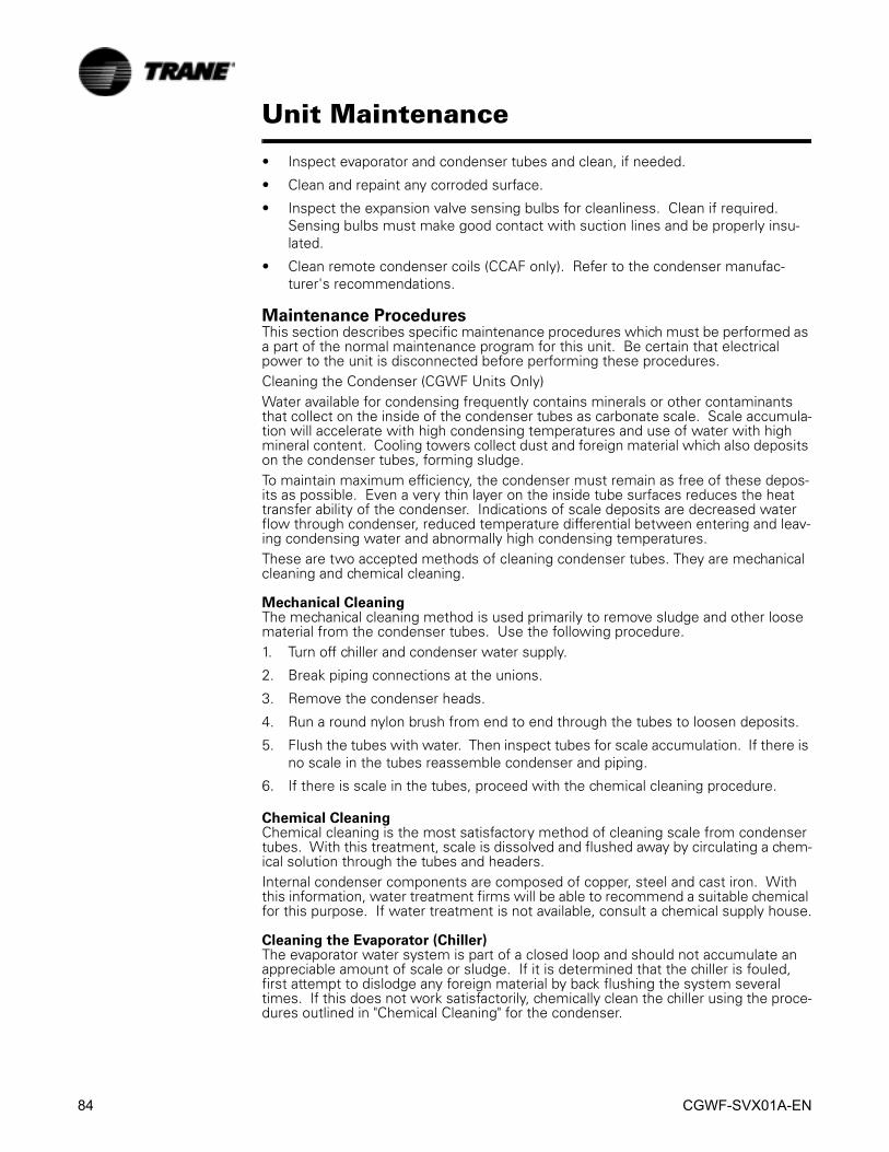
84 CGWF-SVX01A-EN
Unit Maintenance
• Inspect evaporator and condenser tubes and clean, if needed.
• Clean and repaint any corroded surface.
• Inspect the expansion valve sensing bulbs for cleanliness. Clean if required. Sensing bulbs must make good contact with suction lines and be properly insu-lated.
• Clean remote condenser coils (CCAF only). Refer to the condenser manufac-turer's recommendations.
Maintenance ProceduresThis section describes specific maintenance procedures which must be performed as a part of the normal maintenance program for this unit. Be certain that electrical power to the unit is disconnected before performing these procedures.Cleaning the Condenser (CGWF Units Only)Water available for condensing frequently contains minerals or other contaminants that collect on the inside of the condenser tubes as carbonate scale. Scale accumula-tion will accelerate with high condensing temperatures and use of water with high mineral content. Cooling towers collect dust and foreign material which also deposits on the condenser tubes, forming sludge.To maintain maximum efficiency, the condenser must remain as free of these depos-its as possible. Even a very thin layer on the inside tube surfaces reduces the heat transfer ability of the condenser. Indications of scale deposits are decreased water flow through condenser, reduced temperature differential between entering and leav-ing condensing water and abnormally high condensing temperatures.These are two accepted methods of cleaning condenser tubes. They are mechanical cleaning and chemical cleaning.
Mechanical CleaningThe mechanical cleaning method is used primarily to remove sludge and other loose material from the condenser tubes. Use the following procedure.1. Turn off chiller and condenser water supply.
2. Break piping connections at the unions.
3. Remove the condenser heads.
4. Run a round nylon brush from end to end through the tubes to loosen deposits.
5. Flush the tubes with water. Then inspect tubes for scale accumulation. If there is no scale in the tubes reassemble condenser and piping.
6. If there is scale in the tubes, proceed with the chemical cleaning procedure.
Chemical CleaningChemical cleaning is the most satisfactory method of cleaning scale from condenser tubes. With this treatment, scale is dissolved and flushed away by circulating a chem-ical solution through the tubes and headers.Internal condenser components are composed of copper, steel and cast iron. With this information, water treatment firms will be able to recommend a suitable chemical for this purpose. If water treatment is not available, consult a chemical supply house.
Cleaning the Evaporator (Chiller)The evaporator water system is part of a closed loop and should not accumulate an appreciable amount of scale or sludge. If it is determined that the chiller is fouled, first attempt to dislodge any foreign material by back flushing the system several times. If this does not work satisfactorily, chemically clean the chiller using the proce-dures outlined in "Chemical Cleaning" for the condenser.

CGWF-SVX01A-EN 85
Unit Maintenance
CAUTION
Evaporator Damage!
Evaporator internal components are composed of steel, polypropylene
and copper. Do not use an acidic type cleaning agent that will damage
these components.
Proper Water Treatment!
The use of untreated or improperly treated water in a Chiller may result
in scaling, erosion, corrosion, algae or slime. It is recommended that the
services of a qualified water treatment specialist be engaged to
determine what water treatment, if any, is required. Trane assumes no
responsibility for equipment failures which result from untreated or
improperly treated water, or saline or brackish water.
Water TreatmentThe use of untreated or improperly treated water in these units may result in the for-mation of scale, erosion, corrosion, algae or slime. It is recommended that the ser-vices of a qualified water treatment specialist be engaged to determine what treatment, if any, is required. The Trane Company assumes no responsibility for equipment failure that results from the use of untreated or improperly treated water.

86 CGWF-SVX01A-EN
Unit Maintenance
Main Tab 15 min 30 min 1 hrChiller ModeCircuit 1 ModeCircuit 2 ModeEvap Ent/Lvg Water TempCond Ent/Lvg Water TempActive Chilled Water Setpoint (F/C)Average Line Current (%RLA)Active Demand Limit setpoint (F/C)Active Ice Termination Setpoint (F/C)Outdoor Air Temperature (F/C)Software TypeSoftware VersionReports Tab
SystemEvap Entering Water Temperature (F/C)Evap Leaving Water Temperature (F/C)Evap Water Flow Switch StatusCircuit 1Evap Sat Rfgt Temp (F/C)Suction Pressure (psia)Evap Approach TempCircuit 2Evap Sat Rfgt Temp (F/C)Suction Pressure (psia)Evap Approach Temp
SystemCond Entering Water Temperature (F/C)Cond Leaving Water Temperature (F/C)Cond Water Flow Switch StatusOutdoor Air Temperature (F/C)Circuit 1Cond Sat Rfgt Temp (F/C)Discharge Pressure (psia)Cond Approach TempCircuit 2Evap Sat Rfgt Temp (F/C)Suction Pressure (psia)Cond Approach Temp
SystemChiller Running TimeCircuit 1Compressor 1A StartsCompressor 1B StartsCompressor 1A Run TimeCompressor 1B Run TimeCircuit 2Compressor 2A StartsCompressor 2B StartsCompressor 2A Run TimeCompressor 2B Run Time
Compressor
Chiller LogRun Time
Evaporator
Condenser
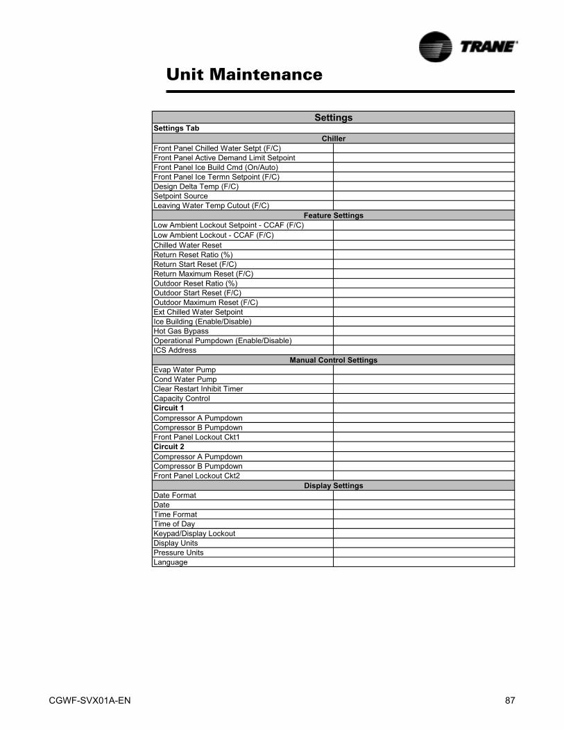
CGWF-SVX01A-EN 87
Unit Maintenance
Settings Tab
Front Panel Chilled Water Setpt (F/C)Front Panel Active Demand Limit SetpointFront Panel Ice Build Cmd (On/Auto)Front Panel Ice Termn Setpoint (F/C)Design Delta Temp (F/C)Setpoint SourceLeaving Water Temp Cutout (F/C)
Low Ambient Lockout Setpoint - CCAF (F/C)Low Ambient Lockout - CCAF (F/C)Chilled Water Reset Return Reset Ratio (%)Return Start Reset (F/C)Return Maximum Reset (F/C)Outdoor Reset Ratio (%)Outdoor Start Reset (F/C)Outdoor Maximum Reset (F/C)Ext Chilled Water SetpointIce Building (Enable/Disable)Hot Gas BypassOperational Pumpdown (Enable/Disable)ICS Address
Evap Water PumpCond Water PumpClear Restart Inhibit TimerCapacity ControlCircuit 1Compressor A PumpdownCompressor B PumpdownFront Panel Lockout Ckt1Circuit 2Compressor A PumpdownCompressor B PumpdownFront Panel Lockout Ckt2
Date FormatDateTime FormatTime of DayKeypad/Display LockoutDisplay UnitsPressure UnitsLanguage
Display Settings
Settings
Chiller
Feature Settings
Manual Control Settings

88 CGWF-SVX01A-EN
Unit Maintenance

CGWF-SVX01A-EN 89
Wiring Schematics
Typical field connection diagrams, electrical schematics and connections diagrams for the CGWF/CCAF units are shown in this section.
NOTE: The drawings in this section are provided for reference only. These diagrams may not reflect the actual wiring of your unit. For specific electrical connection and schematic information, always refer to the wiring diagrams that were shipped with the unit.
Drawing Description IOM Page
2309-7571 Schematics Page 1&2 90
2309-7577 Component Location 94
2309-7578 Field Wiring Diagram 95
2309-7579 Field Layout Diagram 96

90 CGWF-SVX01A-EN
C
A D
IVIS
ION
OF
AM
ER
ICA
N S
TA
ND
AR
D IN
C.
AL
L R
IGH
TS
RE
SE
RV
ED

CGWF-SVX01A-EN 91
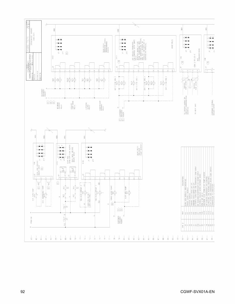
92 CGWF-SVX01A-EN
C
A D
IVIS
ION
OF
AM
ER
ICA
N S
TA
ND
AR
D I
NC
.
ALL
RIG
HT
S R
ES
ER
VE
D
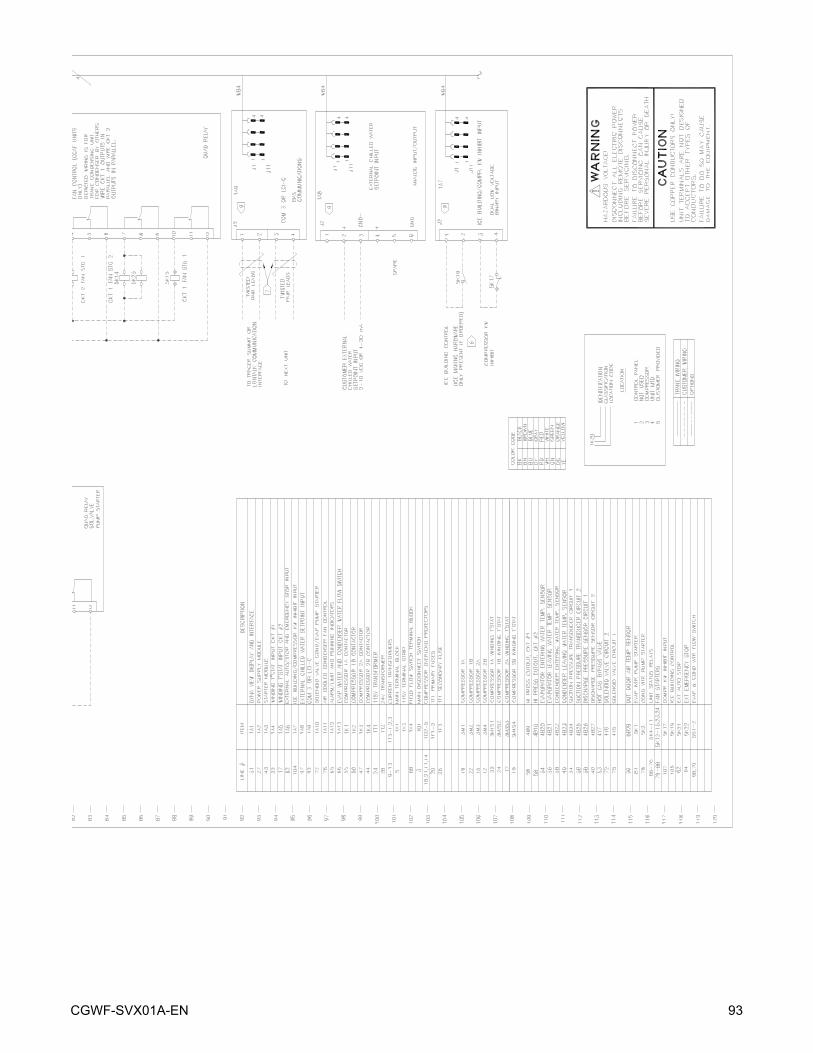
CGWF-SVX01A-EN 93
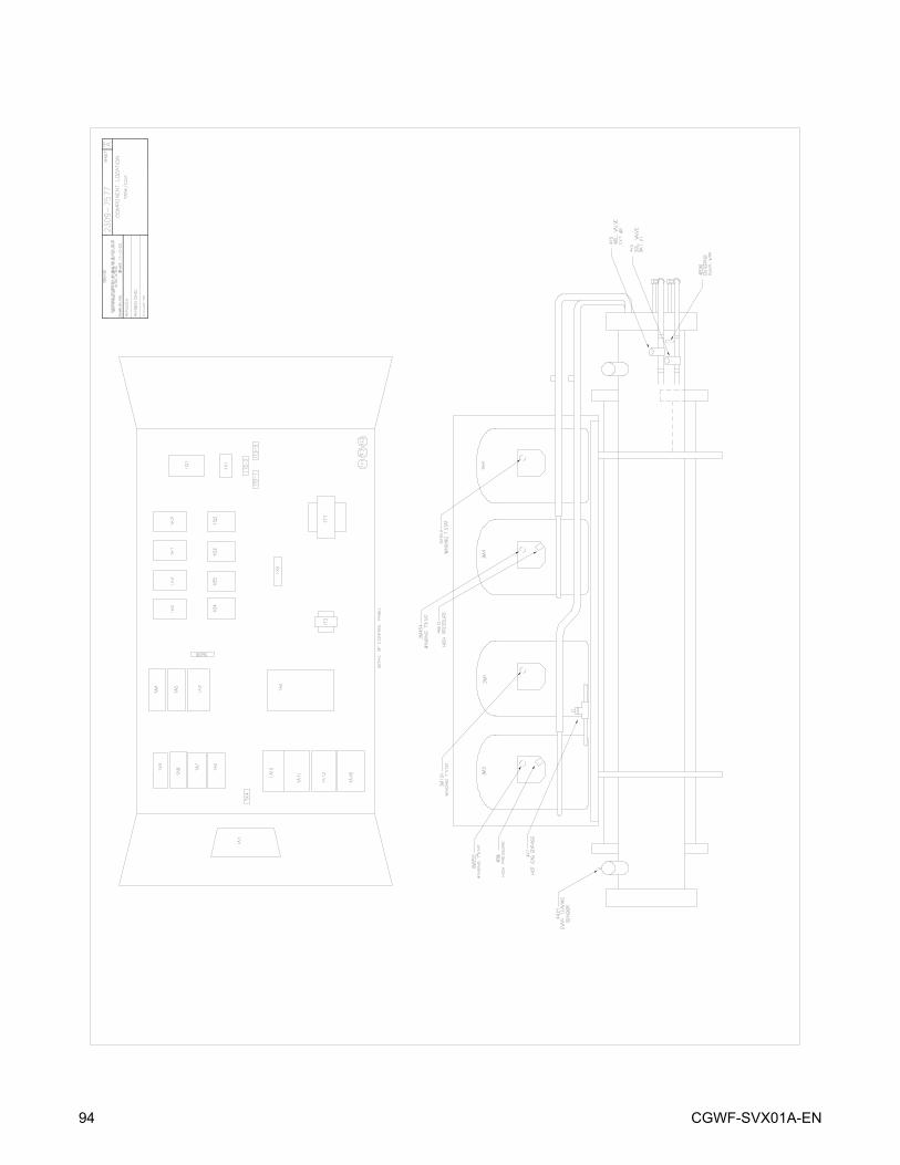
94 CGWF-SVX01A-EN
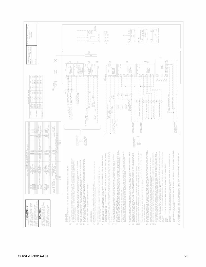
CGWF-SVX01A-EN 95

96 CGWF-SVX01A-EN
CGWF-SVX01A-EN 97
98 CGWF-SVX01A-EN

CGWF-SVX01A-EN 99

Trane has a policy of continuous product data and product improvement and reserves the right to change design and specifications without notice. Only qualified techni-cians should perform the installation and servicing of equipment referred to in this bul-letin.
Literature Order Number CGWF-SVX01A-EN
File Number SV-RF-CGWF-SVX01A-EN-104
Supersedes New
Stocking Location Inland
Trane
A business of American Standard Companieswww.trane.com
For more information contact your local district office or e-mail us at [email protected]