installation operation manual · chapter three: installing the glentek vector drive into a fadal...
TRANSCRIPT

INSTALLATION &
OPERATION MANUAL
Model SMB9675-1A-1-6889
MANUAL#: 9675-1040-000 REVISION: (A) DATE: 30 August 2010
FADAL REPLACEMENT
SENSORED VECTOR DRIVE


TABLE OF CONTENTS CHAPTER ONE: GENERAL 1.1 Overview……………………………………….…………. 2 1.2 Intended Application………………………….…………… 2 CHAPTER TWO: APPLICATION SOFTWARE 2.1 MotionMaestro©……………………………….………… 3 2.2 Installing MotionMaestro©………………………..…….. 3 2.2.1 Requirements………………………...………. 3 2.2.2 MotionMaestro© v1.37………………...……. 3 2.2.3 Installation………………………………...….. 3 2.3 Communicating with the Vector Drive……………….... 4 2.3.1 Serial Port……………………………….…….. 4 2.3.2 USB Port………………………………...……. 4 CHAPTER THREE: INSTALLING THE GLENTEK VECTOR DRIVE INTO A FADAL VMC 3.1 Removing the old drive………………………….………. 5 3.2 Mechanical Installation…………………………….……. 5 3.3 Electrical Installation………………………………….…. 5 3.3.1 Power Terminal Block Connections……..… 5 3.3.2 Load Meter Cable…………………………….. 5 3.3.3 Control Cable…………………………..…….. 5 3.3.4 Wye/Delta Cable…………………………..…. 5 3.3.5 Encoder Feedback Cable……………….….. 5 3.3.6 Rigid Tap Cable (Encoder Output)……….... 5 CHAPTER FOUR: SETUP AND TUNING 4.1 Turning the power on………………………….………… 7 4.2 Establishing Communications……………….…………. 7 4.3 Motor Parameters……………………………….………. 8 4.4 Tuning & Offset Adjustment……………………..……… 9 4.5 Saving Your Setup…………………………….………… 9 4.6 Rigid Tap Test………………………………….………… 9 CHAPTER FIVE: TROUBLESHOOTING AND MAINTENANCE 5.1 Status Display Codes………………..………………….. 11 5.2 Maintenance…………………………..…………………. 11 CHAPTER SIX: WARRANTY, FACTORY REPAIR AND SAFETY 6.1 Warranty……………………..…………………………… 12 6.2 Factory Repair…………..……………………………….. 12 6.3 Safety…………………………..…………………………. 13 DRAWINGS & DIAGRAMS FADAL Vector Drive Installation Drawing……………………. 14 FADAL Vector Drive Installation Drawing……………………. 15 Vector Drive Connection Diagram Sheet 1………………….. 16 Vector Drive Connection Diagram Sheet 2…………………… 17 Sensored Vector Command Input Control Diagram…………. 18 Sensored Vector Velocity Control Loop Diagram……………. 19 Sensored Vector Current Control Loop Diagram……………. 20
1
CHAPTER ONE: GENERAL
1.1. Overview
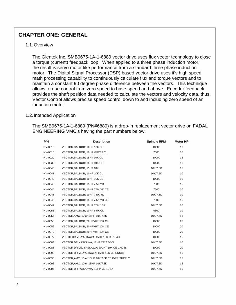
The Glentek Inc. SMB9675-1A-1-6889 vector drive uses flux vector technology to close a torque (current) feedback loop. When applied to a three phase induction motor, the result is servo motor like performance from a standard three phase induction motor. The Digital Signal Processor (DSP) based vector drive uses it’s high speed math processing capability to continuously calculate flux and torque vectors and to maintain a constant 90 degree phase difference between the vectors. This technique allows torque control from zero speed to base speed and above. Encoder feedback provides the shaft position data needed to calculate the vectors and velocity data, thus, Vector Control allows precise speed control down to and including zero speed of an induction motor. 1.2. Intended Application The SMB9675-1A-1-6889 (PN#6889) is a drop-in replacement vector drive on FADAL ENGINEERING VMC’s having the part numbers below.
P/N Description Spindle RPM Motor HP
INV-0015 VECTOR,BALDOR; 10HP 10K CL 10000 10
INV-0016 VECTOR,BALDOR; 10HP VMC15 CL 7500 10
INV-0020 VECTOR,BALDOR; 15HT 10K CL 10000 15
INV-0039 VECTOR,BALDOR; 15HT 10K CE 10000 15
INV-0040 VECTOR,BALDOR; 15HT 10K 10K/7.5K 15
INV-0041 VECTOR,BALDOR; 10HP 10K CL 10K/7.5K 10
INV-0042 VECTOR,BALDOR; 10HP 10K CE 10000 10
INV-0043 VECTOR,BALDOR; 15HT 7.5K YD 7500 15
INV-0044 VECTOR,BALDOR; 10HP 7.5K YD CE 7500 10
INV-0045 VECTOR,BALDOR; 10HP 7.5K YD 10K/7.5K 10
INV-0046 VECTOR,BALDOR; 15HT 7.5K YD CE 7500 15
INV-0049 VECTOR,BALDOR; 10HP 7.5K/10K 10K/7.5K 10
INV-0055 VECTOR,BALDOR; 10HP 6.5K CL 6500 10
INV-0056 VECTOR,AMC; 10 or 15HP 10K/7.5K 10K/7.5K 15
INV-0058 VECTOR,BALDOR; 20HPVHT 10K CL 10000 20
INV-0059 VECTOR,BALDOR; 20HPVHT 10K CE 10000 20
INV-0070 VECTOR,BALDOR; 20HPVHT 10K CE 10000 20
INV-0077 VECTO DRIVE,YASKAWA; 15HT 10K CE 104D 10000 15
INV-0083 VECTOR DR,YASKAWA; 10HP CE 7.5/10L 10K/7.5K 10
INV-0086 VECTOR DRIVE, YASKAWA; 20VHT 10K CE CNC88 10000 20
INV-0093 VECTOR DRIVE,YASKAWA; 15HT 10K CE CNC88 10K/7.5K 15
INV-0095 VECTOR,AMC; 10 or 15HP 10K/7.5K CE PWR SUPPLY 10K/7.5K 15
INV-0096 VECTOR,AMC; 10 or 15HP 10K/7.5K 10K.7.5K 15
INV-0097 VECTOR DR, YASKAWA; 10HP CE 104D 10K/7.5K 10
2

CHAPTER TWO: APPLICATION SOFTWARE
2.1. MotionMaestro© MotionMaestro© is Glentek's Windows based application software that you will need
to setup and tune the vector drive. MotionMaestro© has many features that allow users to easily configure and tune the entire Glentek digital product line. However, for
the Fadal VMC replacement vector drive most of the setup has been done at the factory. The installer only needs go through a quick tuning procedure to get the vector drive up and running. But first MotionMaestro needs to be installed. 2.2. Installing MotionMaestro©
2.2.1. Requirements MotionMaestro© requires Windows95, Windows 98 SE, Windows ME, Windows NT 4.0, Windows 2000 or Windows XP operating system running on a laptop with a serial port or a USB port. It is suggested that you have a minimum of 3 mega bytes of application program disk space available prior to installation.
2.2.2. MotionMaestro© v1.37 Only MotionMaestro© v1.37 or later will work with Glentek Inc. vector drives, earlier versions are not compatible.
2.2.3. Installation
The MotionMaestro© install disk is set up to utilize Install Shield to simplify installation. There are only a few setup options offered. In general you can press NEXT or YES until installation is complete. When installation is complete, you will find a MotionMaestro© icon on the Windows Start\Programs menu. The MotionMaestro© installation program is named Setup.exe. It is found in the MotionMaestro© \disk1 directory of the distribution CD, included with the vector drive. The installation will create a Glentek folder in the Program Files folder. A MotionMaestro© 1.37 folder is created when 1.37 installed. You can have multiple versions of MotionMaestro© installed, if you wish, and they will be placed into their own directories. When MotionMaestro© is directed to establish communications with the amplifier, the amplifier is queried for a model ID and Firmware version. MotionMaestro© will configure itself and select the appropriate configuration files based on the amplifier returned values.
3
4
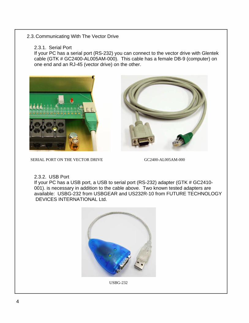
2.3. Communicating With The Vector Drive
2.3.1. Serial Port If your PC has a serial port (RS-232) you can connect to the vector drive with Glentek cable (GTK # GC2400-AL005AM-000). This cable has a female DB-9 (computer) on one end and an RJ-45 (vector drive) on the other.
2.3.2. USB Port If your PC has a USB port, a USB to serial port (RS-232) adapter (GTK # GC2410- 001). is necessary in addition to the cable above. Two known tested adapters are available: USBG-232 from USBGEAR and US232R-10 from FUTURE TECHNOLOGY DEVICES INTERNATIONAL Ltd.
GC2400-AL005AM-000 SERIAL PORT ON THE VECTOR DRIVE
USBG-232

CHAPTER THREE: INSTALLING THE GLENTEK VECTOR DRIVE INTO A FADAL VMC
3.1. Removing the old drive Turn off the power to the VMC and wait 5 minutes before beginning removal. Disconnect all the wires and cables. If any wires are not labeled take note of their location. Of the cables, only the Control cable and the Delta/Wye cable can be confused, both are 6 terminal connectors. The control cable has 6 sockets in the connector and Delta/Wye cable has 3 sockets in the connector. Unbolt the old drive and remove. 3.2. Mechanical Installation Install the new drive (slots down) by first resting the drive on the lower mounting studs in the panel and positioning the drive over the studs at the top. Hold the drive against the panel and loosely install four nuts, top two first. Tighten all four nuts. 3.3. Electrical Installation
3.3.1. Power Terminal Block Connections Begin the wiring by connecting the AC, regenerative braking, motor and green ground wires. Match the wire labels to the terminal block labels. Check connections for tightness. See the appendix for installation drawings. 3.3.2. Load Meter Cable Connect the load meter cable by connecting the black wire to P1-1 screw terminal and the red wire to P1-2. 3.3.3. Control Cable Connect the control cable to P5, the Control cable has 6 sockets installed, do not mistake the Wye/Delta connector with only 3 sockets. 3.3.4. Wye/Delta Cable Connect the Wye/Delta cable to P6 (Wye/Delta is an option, your VMC may not have this cable). 3.3.5. Encoder Feedback Cable Connect the encoder feedback from the motor (9 terminal connector) to P4. 3.3.6. Rigid Tap Cable (Encoder Output To CNC Control) For VMC’s with the Rigid Tap option, connect the rigid tap cable from the CNC to P2 of the vector drive. Use installation drawing 6889-6 (Appendix) to match the wires by color to the correct terminal.
5

6
Before and after photos of a typical installation

7
CHAPTER FOUR: SETUP AND TUNING
4.1. Turning the Power On. Carefully recheck the wiring. Restore power to the VMC. After the VMC is finished initializing, check the vector drive status 7 segment display. One segment may be lighted or if the spindle is rotating slowly you will see a rotating pattern of segments lighting. 4.2. Establishing Communications Connect your laptop to the vector drive at P3. Open MotionMaestro 1.37 or later version and go to the communication menu drop down and select OPEN. The Open Communications dialog box will appear. Press the OK button and the COM status box to the right will turn green.

4.3. Motor Parameters From the Setup menu drop down, open the Induction Motor Vector Control dialog box as seen below. Motor Parameters Section; In the working column enter the Stator Resistance (phase to phase) and the Stator Inductance. The Nominal DC Bus and the Current Loop Bandwidth are preset to 340VDC and 2000 Hz respectively and do not normally need to be changed. Motor Safety Limits; These parameters are preset at the factory and do not normally need to be changed Vector Control Parameters; In the working column enter the parameters listed. Check that your parameters are correct and push the Send to Amp button, The parameters in the working column will appear in the Amp column, next push the Enable Amp button, then the Done button. Close the box and from the Setup menu drop down select Save to NVM. Push the Save button. This will save the parameters in the vector drive.
8

4.4. Tuning & Offset From the Tools menu drop down select the Control Panel dialog box. From the Setup menu drop down select the Analog I/O dialog box. Arrange the boxes side by side. Observe any small rotation in the Actual Velocity box in the control panel dialog. Adjust that rotation to zero by changing the value in the Signal Offset box in the Analog I/O dialog. 4.5. Saving your setup You are almost done setting up. From the Setup menu drop down select Save To NVM. When queried “Save card setup to Non Volatile RAM?” press the Yes button. Setup is complete 4.6 Rigid Tap Test (Optional) If desired you can test the rigid tap mode of your VMC by performing the following procedure. This procedure is drawn from the FADAL maintenance manual. Install test screw (SVT-0077). The screw can be fabricated from 1.000” round stock, by threading a 14 TPI Acme thread. Program is for Format 1. Use test program #6000 or the following program:
9
% N1O6000(RIGID TAP CYCLE N2G80 N3S750 N4G91 N5X0.1Y0.1G1F10. N6M5 N7G4P2000 N8G84.1Z-1.R+0F500.Q0.0714 N9M45 N10X-0.1Y-0.1G1F10. N11M45 N12M45 N13M45 N14M45 N15G80 N16G4P2000 N17M99P5 N18(! N19( NOTE: O5827 CNC88 TEST WAS MOVED TO TA,5!!! % 3801 �

Once the program is loaded jog the z axis down so the screw can be indicated. Type “SETZ” and press ENTER. Start the test program and observe the program is running correctly. Depress the SINGLE STEP key. Be sure the test screw returns to its original position. Set the indicator as shown below, the tip must be touching the lower thread halfway into the thread, the second thread from the bottom. Run the test and observe the indicator. The reading should not deviate from zero More than .002” on either side of zero. If necessary consult the FADAL maintenance manual for your machine.
10
TEST SCREW TEST SCREW W/ TOOL HOLDER
TEST SCREW IN SETUP WITH DIAL INDICATOR

5.2. Maintenance The only maintenance required is to periodically inspect the fans. The blades should be free turning and built up dirt should be removed from the blades.
11
CHAPTER FIVE: TROUBLESHOOTING AND MAINTENANCE 5.1 Status Display Codes
Display Name Description Possible Cause
1 EEPROM Fault
Parameter EEPROM checksum fault Internal problem
8 Reset (Flashing) N/A Internal problem
b Bus Over Voltage
DC bus exceeded 450VDC
Regenerative braking cir-cuit not working, check fuse in regen circuit
C Clamp (Disabled) Vector drive disabled Control is disabling the
drive
E Encoder Fault Encoder fault detected Encoder faulty or en-
coder wiring broken
H Heatsink Over Tem-perature
Heatsink exceeded 65ºC Fan(s) failed
L LS/ECB Motor RMS over cur-rent
Mechanical binding in motor or spindle
0 Normal Op-eration Amp enabled Normal when rotating
S HS/ECB Output short circuit de-tected Motor windings shorting
U Bus Under Voltage
DC bus below 150VDC nominal
AC input voltage to drive is low or off
Single segment
Normal Op-eration Amp enabled Normal @ zero speed
12
CHAPTER SIX: WARRANTY, FACTORY REPAIR AND SAFETY
6.1. Warranty Any product, or part thereof, manufactured by Glentek, Inc., described in this manual, which under normal operating conditions, in the plant of the original purchaser, thereof proves defective in material or workmanship within one year from the date of shipment by us, as determined by an inspection by us, will be repaired or replaced free of charge, FOB our factory, El Segundo, California, U.S.A. provided that you promptly send to us notice of the defect and establish that the product has been properly installed, maintained, and operated within the limits of rated and normal usage, and that no factory sealed adjustments have been tampered with. Glentek's liability is limited to repair or replacement of defective parts.
Any product or part manufactured by others and merely installed by us, such as an electric motor, etc., is specifically not warranted by us and it is agreed that such product or part shall only carry the warranty, if any, supplied by the manufacturer of that part. It is also understood that you must look directly to such manufacturer for any defect, failure, claim or damage caused by such product or part.
Under no circumstances shall Glentek, Inc. or any of our affiliates have any liability whatsoever for claims or damages arising out of the loss of use of any product or part sold to you. Nor shall we have any liability to yourself or anyone for any indirect or consequential damages such as injuries to person and property caused directly or indirectly by the product or part sold to you, and you agree in accepting our product or part to save us harmless from any and all such claim 6.2. Factory Repair Should it become necessary to return a vector drive to Glentek for repair, please follow the procedure described below:
1. Reassemble the unit, if necessary, making certain that all the hardware is in place. 2. Tag the unit with the following information:
A. Serial number and model number. B. Company name, phone number, and name of representative
returning the unit. C. A brief notation explaining the malfunction. D. Date the unit is being returned.
3. Repackage the unit with the same care and fashion in which it was re-ceived. Label the container with the appropriate stickers (e.g.: FRAGILE: HANDLE WITH CARE).
4. Contact a Glentek representative, confirm that the unit is being returned to the factory and obtain an RMA (Return Material Authorization) number. The RMA number must accompany the unit upon return to Glentek.

13
5. Return the unit by the best means possible. The method of freight chosen
will directly affect the timeliness of its return.
6.3. Safety
• Serious or fatal injury can result from failure to work safely on this equipment.
• Only qualified personnel should install and maintain this vector drive.
• The drive has capacitors that remain charged after the power is shutoff.
Wait 5 minutes to allow the capacitors to discharge before removing the cover or working on the drive.
• Be sure the system is properly grounded before applying power.
• Regenerative braking resistors can generate temperatures that ignite
combustible materials or vapors. Keep all combustible materials way from braking resistors.
• Braking resistors should be shielded to prevent burn injuries.
• The motor will rotate when autotuning, take precautions to prevent injury
and damage to equipment.

14

15
FADAL VECTOR DRIVEINSTALLATION DRAWING
6889-16889-1RB
SMB9675
SMB9675-1A-1 B
M.TAGUPA 10MAR10
J.A.M. 10MAR10
J.A.M. 10MAR10
1:1.25 1 1
±0.01±0.005±0.5°
- B INITIAL DRAWING RELEASE 3227 16AUG10 M. TAGUPA J.A.M.
REVISION HISTORYZONE REV DESCRIPTION APPDECO CHANGEDDATE
DRAWING TITLE
SCALE:
.XXX
.XX
125
TOLERANCES ARE AS FOLLOWS:
FINISH:
ANGULAR:
DECIMAL:
APPROVAL
MAXIMUM
==
CHK BY:
APP BY:
=
DWN BY:
DSIZE
DATE
OFSHEETFILE NAME:
CONFIGURATION CODE:
DRAWING NUMBERMODEL REVTHE INFORMATION CONTAINED WITHIN THIS DOCUMENT WASORIGINATED BY AND IS THE EXCLUSIVE PROPERTY OF GLENTEKINC. THIS PROPRIETARY INFORMATION SHALL NOT BE REPRODUCED,TRANSFERRED TO OTHER DOCUMENTS, DISCLOSED TO OTHERS,USED FOR MANUFACTURING OR ANY OTHER PURPOSE WITHOUTPRIOR WRITTEN PERMISSION FROM GLENTEK, INC.
UNLESS OTHERWISE SPECIFIEDDIMENSIONS ARE IN INCHES
<
P2 Encoder Output Connector
2 N/C
TX232RX232
COM232
6
N/CN/C
87
N/C45
3
SIGNAL NAMEN/C
PIN1
Not AvailableAnalog Out
P4 Inverter Encoder Connector PinsP4 Inverter Encoder Connector 9-Pin MolexP5 / P6 Control Connector Pins
Dimension (L x H x W - inches)
P3 Host RJ45
P5 / P6 Control Connectors 6-Pin Molex
Non-Volatile Memory
Storage Temperature
Mounting Hardware
Backup File
Humidity
Amplifier Isolation
Operating Temperature
Current Loop Bandwidth
PWM Switching Frequency
Digitally Tuned
Software Configurable
RS-232 Host Port
at Amplifier turn onSmart Com Initialization
Auto Phasing
Glentek P/N: EJD21F09; Molex P/N: 02-09-1119Glentek P/N: EJ761M09; Molex P/N: 03-06-1092
Glentek P/N: EJ018083; Molex P/N: 87522-8012Glentek P/N: EJD21F06; Molex P/N: 02-06-1103
Glentek P/N: EJ588M06; Molex P/N: 03-09-1064
Logic completely isolated from high voltage output stage
All parameters are stored in non-volatile memory
Mating Connectors
L. 20.75, H. 8.02 W. 11.20
5% to 95% non-condensing
5/16 x .75
-40 °C to +80 °C
6889-5.BK
0 °C to +60 °C
Tunable up to 3 KHz
5 KHz Standard
High speed serial communication interface for set-up
All parameters set digitally. No potentiometers to adjust.RS-232 high speed serial communication interface for
and tuning. 115.2 Kbaud, 8 bits, no parity, 1 stop bit
Glentek's Windows based MotionMaestro software.All parameters are downloaded using the RS232 port /
all gain and PID tuning parameters.
Not Available
Not Available
TM TM
Dedicated Fault Output(Progammable Level)
TTL Compatible
Specifications and Features
Tachometer Feedback
Dedicated Inputs
Auxiliary Analog Input
Pulse & Direction Inputs
Encoder Feedback
Low Speed Electronic
Amplifier Type
Bus OvervoltageBus Undervoltage
Circuit Breaker (LS/ECB)
Analog Command Input
Amplifier Status Indication
Logic Power
Peak Current Output
Continuous Current Output
Fault Protection
AC Input Voltage
Inhibit
Not Available
Not Available
Accepts TTL level encoder signals
Not Available
Latches when programmable current (75 A max.),
Trips nominally at 450 ± 10 VDCTrips nominally at 150 ± 10 VDCSensored Vector Drive±10V for analog velocity command
See Table
240 VAC 3-phase
Logic power is derived from input BUS Voltage.
125 A @ 25°C Ambient (with forced air cooling)
75 A @ 25°C Ambient (with forced air cooling)
Short circuit protection from motor phase to phase,
Powers all amplifier logic and encoders (250 mA max.)
(chassis gnd) Amplifier RMS over current. DC bus
broken wire. Invalid Hall/comm track state. over temperature (switch or thermistor input). Encoder over/under voltage. Amplifier over temperature. Motor
Commutation fault.
motor phase to DC bus, motor phase to case
and time (10 sec max.) exceed limit.
9 EAOUT +
EBOUT -EBOUT +EAOUT -
1112
10
SIGNAL NAMEGND
PIN8
P3 Host Connector
P1 Load Meter Connector
2 RED +
SIGNAL NAMEBLACK -
PIN1
2 +5V
B +INDEX +
B -
6
A -A +
87
GND45
3
SIGNAL NAMESHIELD
PIN1
P4 Encoder Input Connector
INDEX -9
2 N/C
N/CN/C
COMMON FOR WYE DELTA
6
HI GAIN/(LOW GAIN INPUT)45
3
SIGNAL NAMEWYE/(DELTA INPUT)
PIN1
P6 Wye/Delta Connector
2 (SPINDLE REVERSE)
(SPINDLE FAULT)SPINDLE SPEED
CMD COMMON
6
(SPINDLE FORWARD)45
3
SIGNAL NAMESPINDLE COMMON
PIN1
P5 Inverter Control Connector
L2 3 PHASE AC INPUT
NOT AVAILABLEB- OUTPUT
NOT AVAILABLE
B-
REGEN RESISTOR INREGEN RESISTOR IN
R2R1
3 PHASE AC INPUTN/CN/C
L3
SIGNAL NAME3 PHASE AC INPUT
PINL1
Motor Power Connector
B+ OUTPUTB+
MOTOR OUTPUT PHASE MOTOR OUTPUT PHASE
T2T1
MOTOR OUTPUT PHASE T3
S HS/ECBUNDER VOLTAGEU
C CLAMP
NORMAL OPERATION
ENCODER FAULTHEATSINK OVERTEMPH
LO
LS/ECB
E
RESET (FLASHING)BUS OVERVOLTAGE
Status Display
EEPROM FAULTFAULT DESCRIPTION
b8
DISPLAY1

16
L1L2
L3N
CB
-R
1R
2B
+T
1T
2T
3N
C
240
VA
C3Ø
PO
WE
R IN
PU
T
BR
AK
ER
ES
ISTO
RG
TK P
N:
6881
BLK
WH
T
RE
CT
IFIE
RB
RID
GE
&
FIL
TER
CA
PS
IGB
TO
UT
PU
TB
RID
GE
B+
B-
FU
SE
LOW
VO
LTA
GE
PW
R S
UP
PLY
DIG
ITA
LV
EC
TOR
CO
NT
RO
L
I/OC
IRC
UIT
S
EN
CO
DE
RA
C IN
DU
CTI
ON
SP
IND
LE M
OTO
R
FA
DA
L V
EC
TOR
DR
IVE
GLE
NTE
K M
OD
EL:
SM
B 9
675-
1A-1
-688
9
9101112
A+
A-
B+
B-
P2
GR
NR
ED
BR
NY
EL
BLK
SH
IELD
Z+
A+ A- Z-
+5V
GN
D B-
B+
SH
LD
P4P
6
P5
WY
E/D
ELT
A
LOW
GA
IN/H
IGH
GA
INC
OM
FO
R W
YE
DE
LTA
SP
IND
LE S
PE
ED
SP
IND
LE F
AU
LTC
MD
CO
M
SP
IND
LE F
WS
PIN
DLE
RE
V
SP
IND
LE C
OM
P1
CO
M
0 -
2.5V
BLK
RE
DLO
AD
ME
TE
R
2 3 4 51 6 7 8 9
BLU
GR
N
OR
NW
HT
BLK
RE
DB
RN
2 3 4 51 6
2 3 4 51 6R
ED
SH
IELD
PIN
K
PIN
KW
HT
/BLK
CLE
AR
PIN
K
12
14
147
(LA
BE
LED
38)
NC
NC
NC
258
369
6 35 2
146 3
5 289101112
8C
OM
CH
AS
SIS
CO
M
CH
AS
SIS
CO
M
WY
E/
DE
LTA
RE
LAY
SS
EE
PA
GE
2
BLK
BLK
BLK
BU
S O
VE
RV
OLT
AG
EC
LAM
P C
KT
RE
VIS
ION
HIS
TOR
YZ
ON
ER
EVD
ESC
RIP
TIO
NA
PPD
EC
OC
HA
NG
ED
DA
TE
DR
AW
ING
TIT
LE
SC
ALE
:
.XX
X.X
X
125
TO
LER
AN
CE
S A
RE
AS
FOLL
OW
S:
FIN
ISH
:
AN
GU
LA
R:
DE
CIM
AL:
AP
PR
OV
AL
MA
XIM
UM
= =C
HK
BY
:
AP
P B
Y:
=
DW
N B
Y:
DS
IZE
DA
TE
OF
SH
EE
TF
ILE
NA
ME
:
CO
NFI
GU
RA
TIO
N C
OD
E:
DR
AW
ING
NU
MB
ER
MO
DE
LR
EV
TH
E IN
FO
RM
ATI
ON
CO
NTA
INED
WIT
HIN
TH
IS D
OC
UM
ENT
WAS
OR
IGIN
AT
ED
BY
AN
D IS
TH
E E
XC
LUSI
VE P
RO
PER
TY O
F G
LEN
TEK
INC
. TH
IS P
RO
PR
IET
AR
Y IN
FO
RM
ATI
ON
SH
ALL N
OT
BE R
EPR
OD
UC
ED,
TR
AN
SFE
RR
ED T
O O
TH
ER
DO
CU
ME
NT
S, D
ISC
LOS
ED T
O O
THER
S,U
SED
FO
R M
AN
UFA
CT
UR
ING
OR
AN
Y O
THER
PU
RPO
SE W
ITH
OU
TP
RIO
R W
RIT
TE
N P
ER
MIS
SIO
N F
RO
M G
LEN
TEK,
INC
.
UN
LES
S O
TH
ER
WIS
E SP
ECIF
IED
DIM
EN
SIO
NS
AR
E IN
INC
HES
<V
EC
TOR
DR
IVE
CO
NN
EC
TIO
N D
IAG
RA
M
6889
-66
889
-6R
B.D
WG
-
SM
B96
75B
M.
TAG
UP
A1
2MA
R10
C.V
.1
2MA
R10
J.M
.1
2MA
R10
1.5
:11
2
±0.0
1±0
.005
±0.5
°
-B
INIT
IAL
DR
AW
ING
REL
EAS
E3
227
16A
UG
10M
. T
AG
UP
AJ
.M.

17
TE
LEM
EC
AN
IQU
ELC
I D
1810
WH
TT
ELE
ME
CA
NIQ
UE
LCI
D18
10
6 LE
AD
S
SP
IND
LEM
OT
OR
1 2 3 4 5 6
12 L
EA
DS
7 8 9 10 11 12
T1
T2
T3
L1 L2 L3
A1
A2
1314
T1
T2
T3
L1 L2 L3
A1
A2
WH
TB
RN
TO
VE
CT
OR
DR
IVE
(MO
TO
R P
OW
ER
)
HIG
H S
PE
ED
(DE
LTA
)
WH
T/B
LK
PIN
K
TO
VE
CT
OR
DR
IVE
(con
tact
s cl
ose
whe
nco
ntac
tor e
nerg
ized
)
WH
TB
RN
LOW
SP
EE
D(W
YE
)
SP
IND
LE M
OT
OR
JU
NC
TIO
N B
OX
SP
IND
LEM
OT
OR
1 2 3 4 5 6
VE
CT
OR
DR
IVE
CO
NN
EC
TIO
N D
IAG
RA
M
688
9-6
6889
-6R
B.D
WG
-
SM
B9
675
B
M.
TA
GU
PA
16M
AR
10
C.V
.1
6MA
R10
J.M
.1
6MA
R10
1.5:
12
2
±0.0
1±0
.005
±0.5
°
-B
INIT
IAL
DR
AW
ING
RE
LEA
SE
322
716
AU
G10
M. T
AG
UP
AJ
.M.
RE
VIS
ION
HIS
TO
RY
ZO
NE
RE
VD
ES
CR
IPT
ION
AP
PD
EC
OC
HA
NG
ED
DA
TE
DR
AW
ING
TIT
LE
SC
ALE
:
.XX
X.X
X
125
TO
LE
RA
NC
ES
AR
E A
S F
OL
LOW
S:
FIN
ISH
:
AN
GU
LAR
:
DE
CIM
AL:
AP
PR
OV
AL
MA
XIM
UM
= =C
HK
BY
:
AP
P B
Y:
=
DW
N B
Y:
DSIZ
E
DA
TE
OF
SH
EE
TF
ILE
NA
ME
:
CO
NF
IGU
RA
TIO
N C
OD
E:
DR
AW
ING
NU
MB
ER
MO
DE
LR
EV
TH
E I
NF
OR
MA
TIO
N C
ON
TA
INE
D W
ITH
IN T
HIS
DO
CU
ME
NT
WA
SO
RIG
INA
TED
BY
AN
D I
S T
HE
EX
CL
US
IVE
PR
OP
ER
TY O
F G
LEN
TEK
INC
. TH
IS P
RO
PR
IETA
RY
IN
FO
RM
ATI
ON
SH
ALL
NO
T B
E R
EP
RO
DU
CE
D,
TR
AN
SF
ER
RE
D T
O O
TH
ER
DO
CU
ME
NTS
, DIS
CLO
SE
D T
O O
THE
RS
,U
SE
D F
OR
MA
NU
FA
CT
UR
ING
OR
AN
Y O
THE
R P
UR
PO
SE
WIT
HO
UT
PR
IOR
WR
ITT
EN
PE
RM
ISS
ION
FR
OM
GLE
NT
EK
, IN
C.
UN
LE
SS
OT
HE
RW
ISE
SP
EC
IFIE
DD
IME
NS
ION
S A
RE
IN
IN
CH
ES
<

18
Ana
log
Inpu
tV
eloc
ity o
rC
urre
nt C
omm
and
MM
Set
Ana
log
to D
igita
lC
onve
rsio
n
Inpu
t Ana
log
Dea
dban
d(IA
D)
+
+
Sen
sore
d V
ecto
r C
omm
and
Inpu
t Con
trol
Dia
gram
Dig
ital
Com
mun
icat
ion
Por
t
MM
Set
+ Traj
ecto
ry S
lew
-R
ate
Gen
erat
orA
mps
/ S
ec o
rR
PM
/ S
ec(A
L/D
L)
MM
Vie
w
+
MM
Set
∑A
nalo
g In
put
Sca
le
MM
Set
3276
8)IA
S( Mod
e 1
Cur
rent
Com
man
d(S
VC
)
Vel
ocity
Lim
iter
(VL)
MM
Vie
wM
M S
et
Mod
e 2
Vel
ocity
Com
man
d(S
VC
)
To C
urre
nt C
ontr
olLo
op D
iagr
amM
ode
1
To V
eloc
ityC
ontr
ol L
oop
Dia
gram
Cur
rent
Lim
iter
(IL)
MM
Set
∑
Inpu
t Ana
log
Off
set
(IAO
)
Bid
irec
tiona
lS
eria
l Int
erfa
ce:
Can
Ope
n, e
tc

19
Gai
nV
eloc
ityC
omm
and
Inte
ger
Set
tabl
e(G
VC
)
Gai
n V
eloc
ityS
cale
in C
ount
spe
r Int
erru
ptP
ower
of 2
setta
ble
20 =1
28 =25
6(G
VS
)
Mod
e 2
Vel
ocity
Com
man
d(S
VC
)
Vie
w M
M
Low
Pas
sFe
edba
ck fi
lter
+
-
+ +
Sen
sore
d V
ecto
r V
eloc
ity C
ontr
ol L
oop
Dia
gram
Vel
ocity
Err
or
MM
Set
+
+
MM
Set
MM
Set
Raw
Vel
ocity
Est
imat
e
∑
Pro
port
iona
lG
ain
MM
Set
3276
8)G
VP
(
Inte
gral
Gai
n
MM
Set
3276
8)G
VI
(
∑∑
Tach
Gai
n
MM
Set
3276
8)G
VF
(
Der
ivat
ive
Gai
n
MM
Set
256
)G
VD
(
Sca
led
Vel
ocity
MM
Vie
w)S
VS
(±327
67
Mod
e 2
Vel
ocity
Loo
pE
rror
Com
man
dto
Cur
rent
Loo
p(S
VC
)
Vel
ocity
From
Cur
rent
Con
trol
Loo
pD
iagr
am
Mea
sure
d M
otor
Vel
ocity
with
Der
ivat
ive
and
Tach
Gai
n
Mo
de
1C
urr
ent
Co
mm
and
(SV
C)
Mo
de
2V
elo
city
Lo
op
Err
or
Co
man
dfr
om
Vel
oci
tyC
on
tro
l Lo
op
(SV
C)
MM
Vie
w
Loo
p G
ain
Set
at
Uni
ty G
ain
(327
67)
whe
nS
yste
m is
Pro
perly
Phas
ed
(GL)
MM
Set
Pro
gra
mm
able
Biq
uad
Filt
erH
igh
Pass
Low
Pas
sB
and
Pas
sB
and
Reje
ct
Filt
er 1
MM
Set
Pro
gram
mabl
eB
iquad
Filt
er
Hig
h P
ass
Low
Pass
Band
Pass
Ban
d R
eje
ct
Filt
er 2
MM
Set
Pro
gra
mm
able
Biq
uad F
ilter
Hig
h P
ass
Low
Pass
Ban
d P
ass
Band
Rej
ect
Fil
ter
3
MM
Set
Cu
rren
t L
imit
MM
Set
Ro
tor
Flu
xC
urr
ent
(VF
I)
Inve
rse P
ark
Tra
nsfo
rmR
ota
tio
n F
ram
e t
oS
tatio
n F
ram
eco
nve
rsio
n
Par
kT
ran
sfo
rmS
tatio
n F
ram
e t
oR
otatio
n F
ram
eco
nve
rsio
n
Incr
emen
tal
Enc
oder
MM
Vie
w
+
-
+ +
Sen
sore
d V
ecto
r C
urr
ent
Co
ntr
ol L
oo
p D
iag
ram
Ro
tor
Tim
eC
on
stan
t(V
FT
)
MM
Set
In
du
ctio
nM
oto
r
GL
EN
TE
Kcu
sto
m S
pac
eV
ecto
r M
od
ula
tor
conve
rsio
n f
rom
Sta
tion
Fra
me t
o 3
pha
se
Co
mm
uta
tio
nW
ind
ow
fo
r N
um
ber
of
Po
les,
En
cod
erC
ou
nt,
etc
MM
Set
3276
8)G
II(
3276
8)IL(
R
Pro
po
rtio
nal
Gai
n
MM
Set
3276
8)G
IP(
Cur
rent
Sense
Curr
ent
Sen
se
Cur
rent
Sense
ST
Cla
rke
Tra
nsf
orm Φ
→Φ
23
Inte
gra
l Gai
n
Co
mm
uta
tio
nA
ng
le
Mea
sure
dC
urr
ent
(SIA
)(S
TD
)(S
TQ
)
MM
Vie
w
DQ
Cu
rren
tC
om
man
d(S
ID)
(SIQ
)
MM
Vie
w
∑∑
Φ3P
ositi
on
Data
GL
EN
TE
KC
ust
om
16b
it H
igh
Ban
d V
elo
city
Gen
erat
or
Θ
Vel
oci
tyT
o V
elo
city
Co
ntr
ol L
oo
pD
iag
ram
Slip
Est
imat
or
Fie
ldW
eake
nin
g
07
-12
-20
10
20


208 Standard Street, El Segundo, California 90245, USA. Telephone: (310) 322-3026; Fax: (310) 322-7709
www.glentek.com e-mail: [email protected]