installation & operation manual - solar...
TRANSCRIPT

Model # SQ-2220-ID
INSTALLATION & OPERATIONMANUAL
Read all the instructions before installing your solar heating system.

2
How does a solar heating system work?1. Connect your existing pool pump to the solar panel. Your pool pump sends cold water to the solar panel.2. The sun heats the water in the solar panel.3. Warm water is then returned to your swimming pool.
How well does solar heating work?A solar heating system if sized and installed properly will raise your pool watertemperature up to 10
0 F / 6
0 C and extend your swimming season. In order to maximize
the heat, the solar panel must be exposed to sunlight as long as possible. On rainydays and at night the solar panel must be turned off so your pool water doesn't cool.You can accomplish this with the integrated diverter kit. On cloudy days, the solarpanel won't work as well. It is recommended to use a solar blanket or a Liquid SolarBlanket. This will help maintain the heat generated by the solar panel in your pool.
Is a special pump required?If your panel is on the ground beside your pool, you can use your existing pool pump as long as it is in good workingcondition. A 1HP pump will handle a panel placed up to 9 meters (30 ft) away from your pool and one story up.
Where can the solar panel be placed?The solar panel can be placed on the ground.Avoid placing in high traffic areas, as it is notrecommended to walk on the solar panel. The solarpanel can also be mounted on a rack or a roof. Whenmounted, the panel should preferably be facing southand be inclined at a 30
0 to 45
0 degree angle. Don't
face the panel North, because it will not heat. Amounting kit (part#SQ-RMK5) is required for placingthe solar panel on a rack or roof.
How many panels do I need?
Above-GroundRound Pool
Above-GroundOval Pool
No. of Systems In-Ground Pool No. of Systems
Up to 15' Up to 12'x24' 1 Up to 15' x 30' 2
18' to 24' 12'x 28' to 16' x 25' 1 - 2 Up to 16' x 36' 3
27' 16'x 32' to 18' x 34' 2 Up to 20' x 40' 4
# of Panels is the minimum recommended.More panels will give you more heat, faster.
3
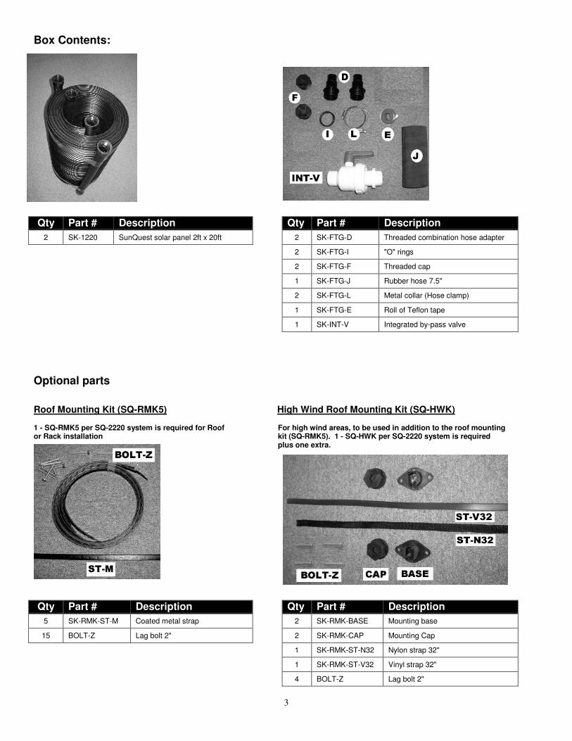
Box Contents:
Qty Part # Description Qty Part # Description
2 SK-1220 SunQuest solar panel 2ft x 20ft 2 SK-FTG-D Threaded combination hose adapter
2 SK-FTG-I "O" rings
2 SK-FTG-F Threaded cap
1 SK-FTG-J Rubber hose 7.5"
2 SK-FTG-L Metal collar (Hose clamp)
1 SK-FTG-E Roll of Teflon tape
1 SK-INT-V Integrated by-pass valve
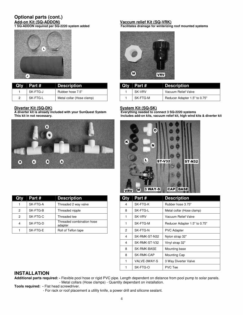
Optional parts
Roof Mounting Kit (SQ-RMK5) High Wind Roof Mounting Kit (SQ-HWK)
1 - SQ-RMK5 per SQ-2220 system is required for Roof For high wind areas, to be used in addition to the roof mountingor Rack installation kit (SQ-RMK5). 1 - SQ-HWK per SQ-2220 system is required
plus one extra.
Qty Part # Description Qty Part # Description
5 SK-RMK-ST-M Coated metal strap 2 SK-RMK-BASE Mounting base
15 BOLT-Z Lag bolt 2" 2 SK-RMK-CAP Mounting Cap
1 SK-RMK-ST-N32 Nylon strap 32"
1 SK-RMK-ST-V32 Vinyl strap 32"
4 BOLT-Z Lag bolt 2"
4
Optional parts (cont.)Add-on Kit (SQ-ADDON) Vaccum relief Kit (SQ-VRK)1 SQ-ADDON required per SQ-2220 system added Facilitates drainage for winterizing roof mounted systems
Qty Part # Description Qty Part # Description
1 SK-FTG-J Rubber hose 7.5" 1 SK-VRV Vacuum Relief Valve
2 SK-FTG-L Metal collar (Hose clamp) 1 SK-FTG-M Reducer Adapter 1.5" to 0.75"
Diverter Kit (SQ-DK) System Kit (SQ-SK)A diverter kit is already included with your SunQuest System Everything needed to connect 3 SQ-2220 systemsThis kit in not necessary. Includes add-on kits, vacuum relief kit, high wind kits & diverter kit
Qty Part # Description Qty Part # Description
1 SK-FTG-A Threaded 2 way valve 4 SK-FTG-K Rubber hose 3.75"
2 SK-FTG-B Threaded nipple 8 SK-FTG-L Metal collar (Hose clamp)
2 SK-FTG-C Threaded tee 1 SK-VRV Vacuum Relief Valve
4 SK-FTG-DThreaded combination hoseadapter
1 SK-FTG-M Reducer Adapter 1.5" to 0.75"
1 SK-FTG-E Roll of Teflon tape 2 SK-FTG-N PVC Adapter
4 SK-RMK-ST-N32 Nylon strap 32"
4 SK-RMK-ST-V32 Vinyl strap 32"
8 SK-RMK-BASE Mounting base
8 SK-RMK-CAP Mounting Cap
1 VALVE-3WAY-S 3 Way Diverter Valve
1 SK-FTG-O PVC Tee
INSTALLATIONAdditional parts required: - Flexible pool hose or rigid PVC pipe. Length dependent on distance from pool pump to solar panels.
- Metal collars (Hose clamps) - Quantity dependant on installation.Tools required: - Flat head screwdriver.
- For rack or roof placement a utility knife, a power drill and silicone sealant.
5
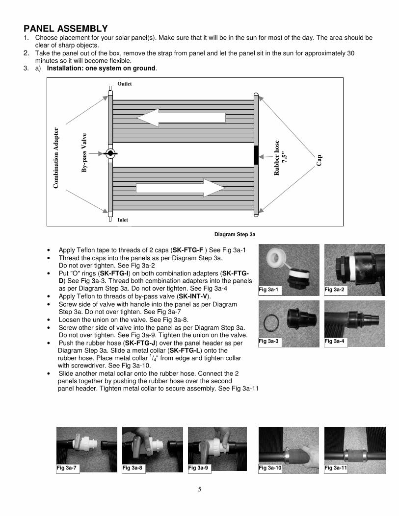
PANEL ASSEMBLY1. Choose placement for your solar panel(s). Make sure that it will be in the sun for most of the day. The area should be
clear of sharp objects.
2. Take the panel out of the box, remove the strap from panel and let the panel sit in the sun for approximately 30minutes so it will become flexible.
3. a) Installation: one system on ground.
Diagram Step 3a
• Apply Teflon tape to threads of 2 caps (SK-FTG-F ) See Fig 3a-1
• Thread the caps into the panels as per Diagram Step 3a.Do not over tighten. See Fig 3a-2
• Put "O" rings (SK-FTG-I) on both combination adapters (SK-FTG-D) See Fig 3a-3. Thread both combination adapters into the panelsas per Diagram Step 3a. Do not over tighten. See Fig 3a-4
• Apply Teflon to threads of by-pass valve (SK-INT-V).
• Screw side of valve with handle into the panel as per DiagramStep 3a. Do not over tighten. See Fig 3a-7
• Loosen the union on the valve. See Fig 3a-8.
• Screw other side of valve into the panel as per Diagram Step 3a.Do not over tighten. See Fig 3a-9. Tighten the union on the valve.
• Push the rubber hose (SK-FTG-J) over the panel header as per Diagram Step 3a. Slide a metal collar (SK-FTG-L) onto the rubber hose. Place metal collar
1/4" from edge and tighten collar
with screwdriver. See Fig 3a-10.
• Slide another metal collar onto the rubber hose. Connect the 2 panels together by pushing the rubber hose over the second panel header. Tighten metal collar to secure assembly. See Fig 3a-11
Co
mb
ina
tio
n A
da
pte
r
By
-pa
ss V
alv
e
Ca
p
Ru
bb
er h
ose
7.5
"Fig 3a-1 Fig 3a-2
Fig 3a-3 Fig 3a-4
Inlet
Outlet
Fig 3a-10 Fig 3a-11Fig 3a-9Fig 3a-8Fig 3a-7
6
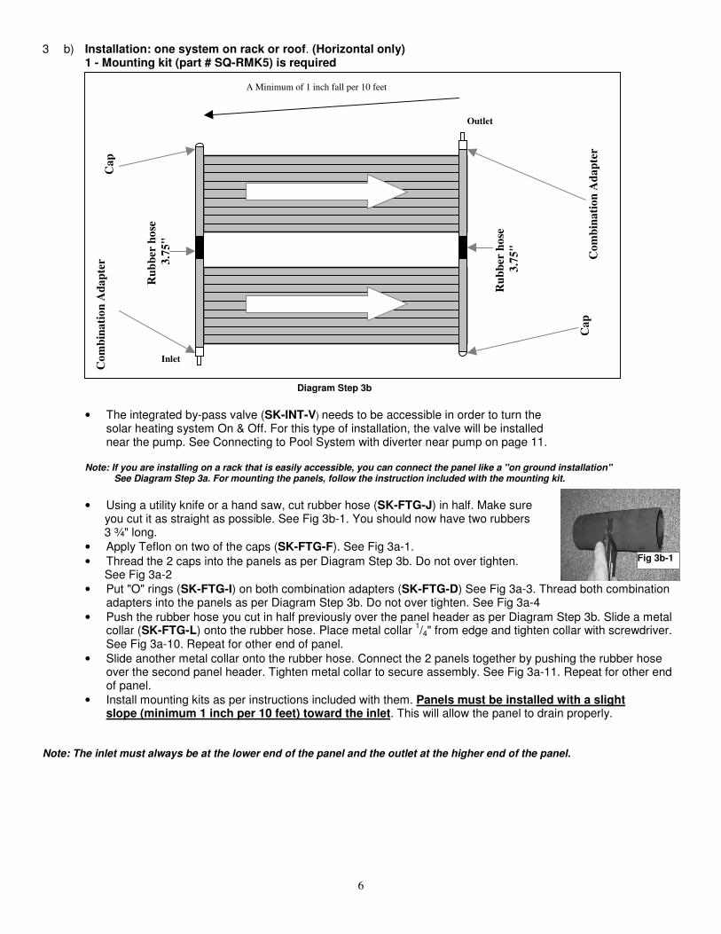
3 b) Installation: one system on rack or roof. (Horizontal only)1 - Mounting kit (part # SQ-RMK5) is required
Diagram Step 3b
• The integrated by-pass valve (SK-INT-V) needs to be accessible in order to turn thesolar heating system On & Off. For this type of installation, the valve will be installednear the pump. See Connecting to Pool System with diverter near pump on page 11.
Note: If you are installing on a rack that is easily accessible, you can connect the panel like a "on ground installation" See Diagram Step 3a. For mounting the panels, follow the instruction included with the mounting kit.
• Using a utility knife or a hand saw, cut rubber hose (SK-FTG-J) in half. Make sure you cut it as straight as possible. See Fig 3b-1. You should now have two rubbers 3 ¾" long.
• Apply Teflon on two of the caps (SK-FTG-F). See Fig 3a-1.
• Thread the 2 caps into the panels as per Diagram Step 3b. Do not over tighten. See Fig 3a-2
• Put "O" rings (SK-FTG-I) on both combination adapters (SK-FTG-D) See Fig 3a-3. Thread both combinationadapters into the panels as per Diagram Step 3b. Do not over tighten. See Fig 3a-4
• Push the rubber hose you cut in half previously over the panel header as per Diagram Step 3b. Slide a metalcollar (SK-FTG-L) onto the rubber hose. Place metal collar
1/4" from edge and tighten collar with screwdriver.
See Fig 3a-10. Repeat for other end of panel.
• Slide another metal collar onto the rubber hose. Connect the 2 panels together by pushing the rubber hoseover the second panel header. Tighten metal collar to secure assembly. See Fig 3a-11. Repeat for other endof panel.
• Install mounting kits as per instructions included with them. Panels must be installed with a slightslope (minimum 1 inch per 10 feet) toward the inlet. This will allow the panel to drain properly.
Note: The inlet must always be at the lower end of the panel and the outlet at the higher end of the panel.
Ca
p
Ca
p
Ru
bb
er h
ose
3.7
5"
Ru
bb
er h
ose
3.7
5"
Fig 3b-1
Inlet
Outlet
A Minimum of 1 inch fall per 10 feet
Co
mb
ina
tio
n A
da
pte
r Co
mb
ina
tio
n A
da
pte
r

7
3. c) Installation: two systems on ground. Add-on kit (part # SQ-ADDON) is required.
Diagram Step 3c
• Using a utility knife or a hand saw, cut both rubber hose (SK-FTG-J ) in half. Make sure you cut it as straightas possible. See Fig 3b-1. You should now have four rubbers 3 ¾" long.
• Apply Teflon tape to threads of two of the caps (SK-FTG-F ) See Fig 3a-1
• Thread the caps into the panels as per Diagram Step 3c. Do not over tighten. See Fig 3a-2
• Put "O" rings (SK-FTG-I) on two combination adapters (SK-FTG-D) See Fig 3a-3. Thread both combinationadapters into the panels as per Diagram Step 3c. Do not over tighten. See Fig 3a-4
• Push the rubber hose you cut in half previously over the panel header as per Diagram Step 3b. Slide a metalcollar (SK-FTG-L) onto the rubber hose. Place metal collar
1/4" from edge and tighten collar with screwdriver.
See Fig 3a-10. Repeat for other end of panel.
• Slide another metal collar onto the rubber hose. Connect the 2 panels together by pushing the rubber hoseover the second panel header. Tighten metal collar to secure assembly. See Fig 3a-11. Repeat for other endof panel.
• Repeat previous 2 steps for second set of panels. You will use the by-pass valve (SK-INT-V) and the Add-onkit (SQ-ADDON) to connect the two sets of panels together.
• Apply Teflon to threads of by-pass valve (SK-INT-V).
• Screw side of valve with handle into the panel as per Diagram Step 3c. Do not over tighten. See Fig 3a-7
• Loosen the union on the valve. See Fig 3a-8.
• Screw other side of valve into the panel as per Diagram Step 3c. Do not over tighten. See Fig 3a-9
• Install Add-on kit (SQ-ADDON) between two sets of panels.
Note: A maximum of 6 2ft panels ( 3 systems ) may be plumbed in series
Ca
p
Ru
bb
er h
ose
3.7
5"
Ca
p
Ru
bb
er h
ose
3.7
5"
Ru
bb
er h
ose
7.5
"
(Ad
d-o
n k
it)
Inlet
Outlet
By
-pa
ss V
alv
e
Co
mb
ina
tio
n A
da
pte
rC
om
bin
ati
on
Ad
ap
ter
Ru
bb
er h
ose
3.7
5"
Ru
bb
er h
ose
3.7
5"
8
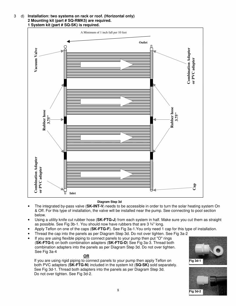
3 d) Installation: two systems on rack or roof. (Horizontal only)2 Mounting kit (part # SQ-RMK5) are required.1 System kit (part # SQ-SK) is required.
Diagram Step 3d
• The integrated by-pass valve (SK-INT-V) needs to be accessible in order to turn the solar heating system On& Off. For this type of installation, the valve will be installed near the pump. See connecting to pool sectionbelow.
• Using a utility knife cut rubber hose (SK-FTG-J) from each system in half. Make sure you cut them as straightas possible. See Fig 3b-1. You should now have rubbers that are 3 ¾" long.
• Apply Teflon on one of the caps (SK-FTG-F). See Fig 3a-1.You only need 1 cap for this type of installation.
• Thread the cap into the panels as per Diagram Step 3d. Do not over tighten. See Fig 3a-2
• If you are using flexible piping to connect panels to your pump then put "O" rings(SK-FTG-I) on both combination adapters (SK-FTG-D) See Fig 3a-3. Thread bothcombination adapters into the panels as per Diagram Step 3d. Do not over tighten.See Fig 3a-4
OR If you are using rigid piping to connect panels to your pump then apply Teflon on both PVC adapters (SK-FTG-N) included in the system kit (SQ-SK) sold separately. See Fig 3d-1. Thread both adapters into the panels as per Diagram Step 3d. Do not over tighten. See Fig 3d-2.
Va
cuu
m V
alv
e
Ru
bb
er h
ose
3.7
5"
Co
mb
ina
tio
n A
da
pte
r
or
PV
C a
da
pte
r
Outlet
Co
mb
ina
tio
n A
da
pte
r
or
PV
C a
da
pte
r
Ca
p
Ru
bb
er h
ose
3.7
5"
Inlet
Fig 3d-1
A Minimum of 1 inch fall per 10 feet
Fig 3d-2

9
3 d) Cont.
• Apply Teflon on reducer adapter (SK-FTG-M) included in the system kit (SQ-SK) soldseparately. Thread reducer adapter into the panel as per diagram Step 3d.Do not over tighten. See Fig 3d-3.
• Apply Teflon on vacuum relief valve (SK-VRV). Thread vacuum relief valve into the reducer adapter. Do not over tighten. See Fig 3d-3.
Note: The vacuum valve assembly must be installed at the top of the panels as per diagram Step 3d.
• Push the rubber hose you cut in half previously over the panel header as per diagramStep 3d. Slide a metal collar (SK-FTG-L ) onto the rubber hose. Place metal collar
1/4"
from edge and tighten collar with screwdriver. See Fig 3a-10. Repeat for other end ofpanel.
• Slide another metal collar onto the rubber hose. Connect the 2 panels together bypushing the rubber hose over the second panel header. Tighten metal collar to secureassembly. See Fig 3a-11. Repeat for other end of panel.
• Repeat previous 2 steps for other system.
• You should now have two sets of connected panels. You need to use rubbers from the systemkit (SK-FTG-K ) to connect the two set together as per Diagram Step 3d.
• Install mounting kits as per instructions included with them. Panels must be installed with a slight slope (minimum 1 inch per 10 feet) toward the inlet. This will allow the panel to drain properly.
Note: The inlet must always be at the lower end of the panel and the outlet at the higher end of the panel.
Note: A maximum of 12 2ft panels (6 systems) may be plumbed in parallel
• For high wind areas you can install the Nylon straps and Vinyl straps from System Kit.Mark a spot 6" to the right of the outlet. Mark spots 6" to the right of every secondrubber hose that are on the same side as the outlet. Mark a spot 6" to the right of thecap. See Fig 3d-4. Place mounting base (SK-RMK-BASE) on these spots. Drill pilotholes, apply silicone roof sealant and screw mounting base into roof. See Fig 3d-5.Wrap a Nylon strap (SK-RMK-ST-N32) around the panel header (see Fig 3d-7) oraround rubber hose (see Fig 3d-6). Lay both ends of strap in the mounting base andpull tight. See Fig 3d-8. Screw on mounting cap.( SK-RMK-CAP). See Fig 3d-9.Repeat process on the inlet side of the panels but using the Vinyl straps (SK-RMK-ST-V32)instead.
Fig 3d-3
Fig 3d-6Fig 3d-5Fig 3d-4
Fig 3d-7 Fig 3d-8 Fig 3d-9

10
CONNECTING TO POOL
System with integrated diverter
Diagram C-1
1. Turn off your pool pump. Block the inlet and outlet of your pool so that the water won't emptywhen you are connecting your panel(s).
2. Remove the hose from the pool inlet ( hose between the filter and the pool ) and connect the hose to the panel inlet. If hose is too short, you need to purchase a new one. Make sure you purchase the appropriate size that is compatible with your existing pool equipment. Place metal collar
1/4" from edge and tighten collar with screwdriver. See Diagram C-1.
3. Connect another hose (not supplied) from the panel outlet to the pool inlet. See Diagram C-1.4. Make sure that your hoses are all connected the correct way and that all the collars have been tightened. Unblock the inlet and outlet of your pool.5. Make sure the valve on the integrated diverter is on the open position. See Fig C1-1.
Valve in the open position Valve in the closed position Solar heating is OFF ( not heating ) Solar heating is ON ( heating )
6. Turn on your pool pump. Check for any leaks. If any of the threaded fittings leak, remove the fitting and apply moreTeflon. If any of the hoses leak at the connection, loosen the collar and push the hose over the fitting and re-tightenthe metal collar. You will see air bubbles coming from the pool inlet. This is normal, the air in the hoses is beingpurged.
7. Turn your solar heating system on by turning the integrated diverter to the closed position. See Fig C1-2.Once again you will see air bubbles coming from your pool. The system is now purging the air that is in the
solar panel(s).
Swimming Pool
Filter
Pump
Pool Outlet Pool Inlet
To Panel
Inlet
From Panel
Outlet
Fig C1-1 Fig C1-2
11
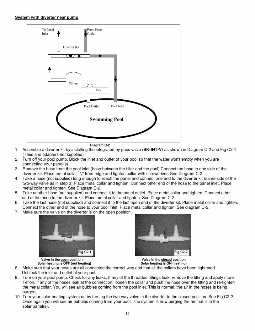
System with diverter near pump
Diagram C-2
1. Assemble a diverter kit by installing the integrated by-pass valve (SK-INT-V) as shown in Diagram C-2 and Fig C2-1.(Tees and adapters not supplied)
2. Turn off your pool pump. Block the inlet and outlet of your pool so that the water won't empty when you areconnecting your panel(s).
3. Remove the hose from the pool inlet (hose between the filter and the pool) Connect the hose to one side of thediverter kit. Place metal collar
1/4" from edge and tighten collar with screwdriver. See Diagram C-2.
4. Take a hose (not supplied) long enough to reach the panel and connect one end to the diverter kit (same side of thetwo-way valve as in step 3) Place metal collar and tighten. Connect other end of the hose to the panel inlet. Placemetal collar and tighten. See Diagram C-2.
5. Take another hose (not supplied) and connect it to the panel outlet. Place metal collar and tighten. Connect other end of the hose to the diverter kit. Place metal collar and tighten. See Diagram C-2.6. Take the last hose (not supplied) and connect it to the last open end of the diverter kit. Place metal collar and tighten.
Connect the other end of the hose to your pool inlet. Place metal collar and tighten. See diagram C-2.7. Make sure the valve on the diverter is on the open position.
Valve in the open position Valve in the closed position Solar heating is OFF (not heating) Solar heating is ON (heating)
8. Make sure that your hoses are all connected the correct way and that all the collars have been tightened. Unblock the inlet and outlet of your pool.9. Turn on your pool pump. Check for any leaks. If any of the threaded fittings leak, remove the fitting and apply more
Teflon. If any of the hoses leak at the connection, loosen the collar and push the hose over the fitting and re-tightenthe metal collar. You will see air bubbles coming from the pool inlet. This is normal, the air in the hoses is beingpurged.
10. Turn your solar heating system on by turning the two-way valve in the diverter to the closed position. See Fig C2-2.Once again you will see air bubbles coming from your pool. The system is now purging the air that is in thesolar panel(s).
Diverter Kit
Swimming Pool
Filter
Pump
Pool Outlet Pool Inlet
To Panel
Inlet
From Panel
Outlet
Fig C2-1 Fig C2-2

12
System with system kit (part # SQ-SK)
Diagram C-3
1. Turn off your pool pump. Block the inlet and outlet of your pool so that the water won't empty when you areconnecting your panel(s).
2. Install Three Way Diverter Valve (VALVE-3WAY-S) and the PVC Tee (SK-FTG-O) on pool return line after filter. SeeDiagram C-3. If you have another pool heater, the three-way valve and tee should be installed before it.
3. You may want to install a check valve between the three-way valve and your filter. This will prevent the water that is inthe panels from flowing backwards into the filter when your pump is turned off. If you install a check valve, make surewhen you winterize your pool that all your piping in drained.
4. Run you feed and return PVC piping from your pool to your solar panels. Make sure piping is installed in such a wayto allow proper drainage.
5. Make sure that your piping is connected the correct way and that all joints have been glued. Unblock the inlet andoutlet of your pool.
6. Turn on your pool pump. Check for any leaks. You will see air bubbles coming from the pool inlet. This is normal, theair in the hoses is being purged.
7. Turn your solar heating system on by turning the three-way diverter valve. Once again you will see air bubbles comingfrom your pool. The system is now purging the air that is in the solar panel(s).
Note: A motorized valve and Automatic controls are optional items available from your local pool dealer
Three Way
Valve
Swimming Pool
Filter
Pump
Pool Outlet Pool Inlet
To Panel
Inlet
From Panel
Outlet
PVC Tee

13
Operation and Maintenance
Turn on your solar heating system whenever the panel(s) are in sunlight. You will know the panel is working by touching it,it should feel cool to the touch. That means the heat from the sun is being transferred to the water inside the panel. Turnoff your solar heating system at night and whenever it is raining. Failing to do so will cool your pool. It is recommended toclose your solar heating system whenever you do a backwash or whenever you manually vacuum your swimming pool. Itis also recommended to use a solar blanket or a Liquid Solar Blanket. This will help keep more of the heat generated bythe solar panel in your pool.
Winterizing
System(s) on ground
At the end of the season, your solar panels must be drained of all water.
• After your pool has been closed, disconnect the hoses from the panel.
• Manipulate the panel until the water is completely out.
• Roll the panel up.
• Store the panel in a heated place until next season.
System(s) mounted on a roof or a rack
At the end of the season, your solar panels must be drained of all water.
• After your pool has been closed, turn your by-bass valve in such a way to allow the water from your panels todrain. Wait half an hour for panels to drain.
• Unscrew the Vacuum Relief Valve or the Threaded cap at the top of the solar system.
• Unscrew the Threaded cap at the bottom of the solar system and make sure all the water is drained out of thesystem. All your plumbing should be installed in such a way to allow full drainage of system. If you are notsure that all panels have been drained properly: disconnect each panel, raise them up and make sure that nowater is present. Once completely drained, the panels can be left on the roof or rack. The SunQuest panelsare designed to withstand the harshest winters.
• Apply Teflon to the Vacuum Relief Valve and Threaded Caps and re-screw them into the solar system. Do notover tighten.
Important: Unlike the pipes for your pool, blowing air in the panel will not drain it. The air will only empty a few tubes.
Internal Freeze damage is not covered by the warranty.
TroubleshootingIf you have any issues with your SunQuest, you can visit our website www.sunquestsolarpanel.com and review ourfrequently asked questions section.
You can also contact our customer support department at 1-888-357-6527
Sunsolar Energy Technologies Inc3262 F-X Tessier
Vaudreuil-Dorion, Qc, CanJ7V 5V5
14
WARRANTY REGISTRATION
Please enter your Warranty Registration on line at: www.sunquestsolarpanel.com
or
Please complete and mail to the address below:
Name : Phone # : ( )
Address :
City : Prov/State : Postal/Zip Code :
Dealer name : Date of purchase :
Retail Price : Pool size : Signature :
Sunsolar Energy Technologies Inc
3262 F-X Tessier
Vaudreuil-Dorion, Qc, J7V 5V5
SunQuest Solar Panel
Five Year Limited Warranty
Five year limited warranty from date of purchase with one full year. After the first year, the claimant shall pay the list price at the date of the claim
less one-sixtieth ( 1/60 ) of the price for each full month remaining in the warranty period. Sunsolar Energy Technologies Inc. warrants to the
original purchaser of the Solar Panel that the company will, at its option, repair or replace any solar panel that proves to be defective in either
workmanship or material upon prepaid return of the solar panel by the owner to Sunsolar Energy Technologies Inc subject to the provisions of the
limited warranty stated above, and the exclusion and limitations set forth below.
What is covered : The solar collector is warranted to be free of defects in material and workmanship when leaving the factory.
What is not covered : Hardware; including hoses, clamps and plastic fittings; any damage due to freezing caused by or related to improper drainage,
winterization, or storage. Damage, defects, malfunctions, or other failures arising from use of the product which does not comply with the
instructions provided by the manufacturer. Damage, defects, malfunctions, or other failures caused by or related to repairs performed by any servicer
other than an authorized service representative of Sunsolar Energy Technologies Inc. Claims will not be accepted for a solar panel's damage in
transit unless damage to shipping container is noted at time of delivery on the transport company's delivery bill.
Sunsolar Energy Technologies Inc shall in no way be liable or responsible under any circumstances or in any amount for any consequential or
incidental damages or for any injury or damages to person or property using or used in connection with this product, or for loss of profits or other
costs or expenses of any kind or character. There are no other warranties or representations, either express or implied, whether of merchantability,
fitness for a particular purpose, or other, made by Sunsolar Energy Technologies Inc., other than those specifically set forth in this warranty. No
person, firm, or corporation is authorized to make any representations, or incur any obligations in the name of or on behalf of Sunsolar Energy
Technologies Inc. except as stated herein. This warranty is expressly understood to be the exclusive remedy available to the purchaser, and this
warranty contains the full and complete agreement between Sunsolar Energy Technologies Inc and the purchaser. This warranty sets forth the only
obligations of Sunsolar Energy Technologies Inc. with regard to this product, and there are no warranties which extend beyond the description on
the face hereof.
To file a claim : Call 1-888-357-6527 to initiate a claim. Please allow 2-4 weeks for warranty claims to be settled.
The representation set forth herein are the only representations made by Sunsolar Energy Technologies Inc with respect to the product, and this
warranty does not constitute either a performance or satisfaction guarantee. It is the responsibility of the product owner to regularly test and check
the product for proper function and safety.
Sunsolar Energy Technologies Inc., 3262 F-X Tessier, Vaudreuil-Dorion, Qc, J7V 5V5