installation, operations & maintenance manual...4 product information cleanawater hydrocyclone...
TRANSCRIPT

Melbourne - Perth - Brisbane - [email protected]
cleanawater.com.au
1800 353 788
DEOIL3 & DEOIL5 Air Hydrocyclone Oil Separator
Installation, Operations & Maintenance Manual
1
TABLE OF CONTENTS
COMPANY INFORMATION 2
PARTS INCLUSION LIST 3
PRODUCT INFORMATION 4
SYSTEM SPECIFICATIONS
DEOIL3 AIR 6
DEOIL5 AIR 9
DEOILER HYDROCYCLONE DETAIL 12
WASTE OIL DECANT TANK DETAIL 13
DEBRIS STRAINER DETAIL 15
TYPICAL INSTALLATION SCHEMATIC 16
INSTALLATION INSTRUCTIONS 19
FINAL INSTALLATION CHECKLIST 23
OPERATIONS & MAINTENANCE GUIDE
OPERATIONS GUIDE 24
MAINTENANCE GUIDE 26
FORTNIGHTLY MAINTENANCE 27
QUARTERLY MAINTENANCE 27
ANNUAL MAINTENANCE 30
SERVICING HELPDESK 30
WARRANTY TERMS 31
TROUBLESHOOTING GUIDE 32
CLEANAWATER TERMS & CONDITIONS 36
PUMP MANUALS & CONNECTION DIAGRAMS REAR

2
COMPANY INFORMATION
Water Sustainability is a key to our economic and environmental future
As one of Australia's leading providers of water treatment and recycling solutions; Cleanawater is
committed to building a sustainable future.
Since 1996 our technologies have been helping businesses achieve cleaner water solutions that are both
cost effective and authority and regulatory compliant.
Cleanawater is a 100% Australian owned and operated water technology company that has been
providing water treatment and recycling solutions throughout Australiasia for over 17 years. Our
manufacturing and research and development centre are based out of our head office in Thomastown,
Victoria, with offices located in Brisbane, Perth and Adelaide.
Our product range includes:
Largest Range of Oil Water Separators – Coalescing, VGS, Hydrocyclone and Induced Cyclonic
Separators
Water Recycling Systems
First Flush Diversion / Stormwater Management Systems
Rainwater Harvesting Systems
AQIS Treatment Systems
Packaged Pumping Stations
pH & Chemical Control Systems
Oil Skimmers – floating oil skimmers / belt oil skimmers

3
PARTS INCLUSION LIST
Your package should include the following items. Please check these items off as received. If any items
are missing please contact Cleanawater on 1800 353 788.
Note: If your package is a non-standard package additional/other items may be included in your package.
Item Qty Included
(Y/N)
Oil Separator &
Components
Your package comes pre plumbed and pre wired and includes the
following items:
Hot Dipped Galvanized Skid 1169mm L x 1169mm W (factory fitted) 1
Deoiling Hydrocyclone Oil Separator (factory fitted) DEOIL3 = 1,
DEOIL5 = 2
1 OR 2
Debris Strainer (factory fitted) 1
Waste Oil Decant Tank – 650 litre (factory fitted) 1
Floating Oil Skimmer and 6 meters flexible suction hose 1
Installation, Operations and Maintenance manual 1
Oil Separator Feed
Pump(s)
RAN / ARO Air Double Diaphragm Feed Pump (note other models
may be included based on availability – refer to your pump manual
attached for model information)
1
Controls Pneumatic Float Switch with pump start / stop levels 1
Pneumatic Air Control Enclosure with all air control requirements
Refer to pneumatic diagram for all function information
1
Optional Extras Other items may be included in your package based on your specific
site requirements, refer to your packing slip or contact Cleanawater
on 1800 353 788 for confirmation.

4
PRODUCT INFORMATION
Cleanawater Hydrocyclone oil separators operate
on the process where wastewater enters the
cyclone chamber and is spun under extreme
centrifugal forces up to 1000 times the force of
gravity.
The heavier water phase is forced outward
towards the cyclone wall where the lighter oil
phase migrates towards the centre core.
The separated oil is discharged from one end of
the cyclone where treated water is discharged
through the opposite end for further treatment,
filtration or discharge.
Solids hydrocyclones are often coupled with de-
oiling hydrocyclones to also remove suspended
solids from waste water which allow them to be
recycled water adaptable and to adhere to strict
discharge specifications.
Hydrocyclone oil separators are a proven oil
water separation method with a history of use in
oil and gas industries and industrial water
treatment applications.

5
Commonly Used in Commercial and Industrial Applications including but not limited to:
Mining Workshops
Mining LV/HV Wash Down Bays
Wash Down Bays
Industrial & Mechanical Workshops
Service Stations
Refuelling Areas
Contaminated Stormwater Runoff
Manual and Automatic Car Washes
Oil Spill Control
Refineries
Food and Beverage Plants
Transformer Bunds
Effluent standards for the Cleanawater DEOILER oil water separators adhere to the WSAA Product
Specification WSA PS 810, Separator Systems for Light Liquids as listed below.
a. Total Grease 50 mg/L
b. Petroleum Hydrocarbons including BTEX 10mg/L
c. Benzene 0.1mg/L
d. Suspended Solids 200mg/L
e. Flammability < 5% LEL (hexane) at 25OC
f. pH 7-10
Note:
- Quick break and bio degradable detergents and degreasers should be used in conjunction with the system.
- Holding pit capacity should match the hourly throughput of the oil separator system.
- Any solvent based liquids or emulsifiers should be avoided, these may affect the efficiency of the unit performance.
- DEOILER oil separators are designed to remove free oils and grease and hydrocarbons, emulsified and dissolved hydrocarbons may require
additional treatment
- Total suspended solids discharge based on historical test results via a 3mm debris strainer

6
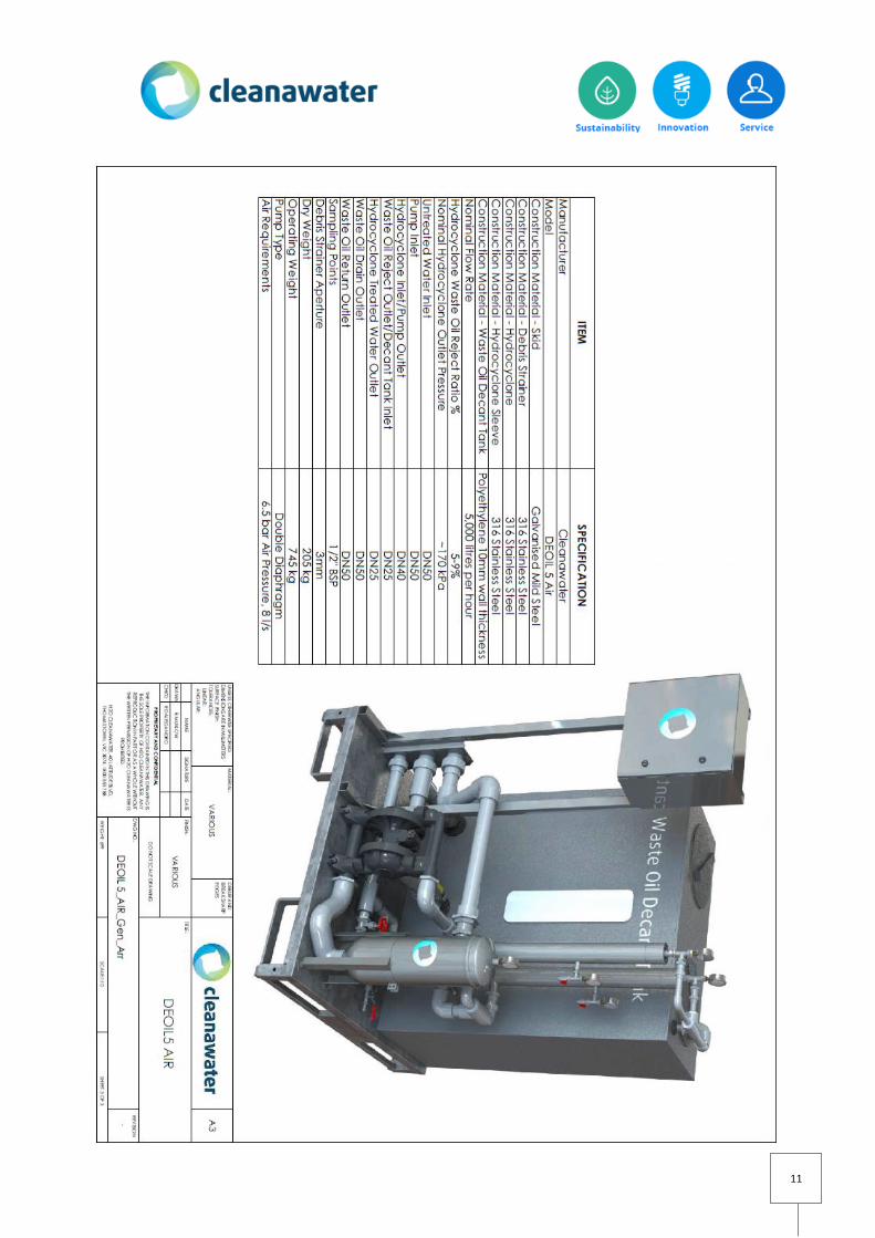
SYSTEM SPECIFICATIONS
Refer to your specification plate for confirmation on your system model. Your system comes complete
with major components listed in the following specifications below.

7

8

9

10
11

12

13

14

15

16
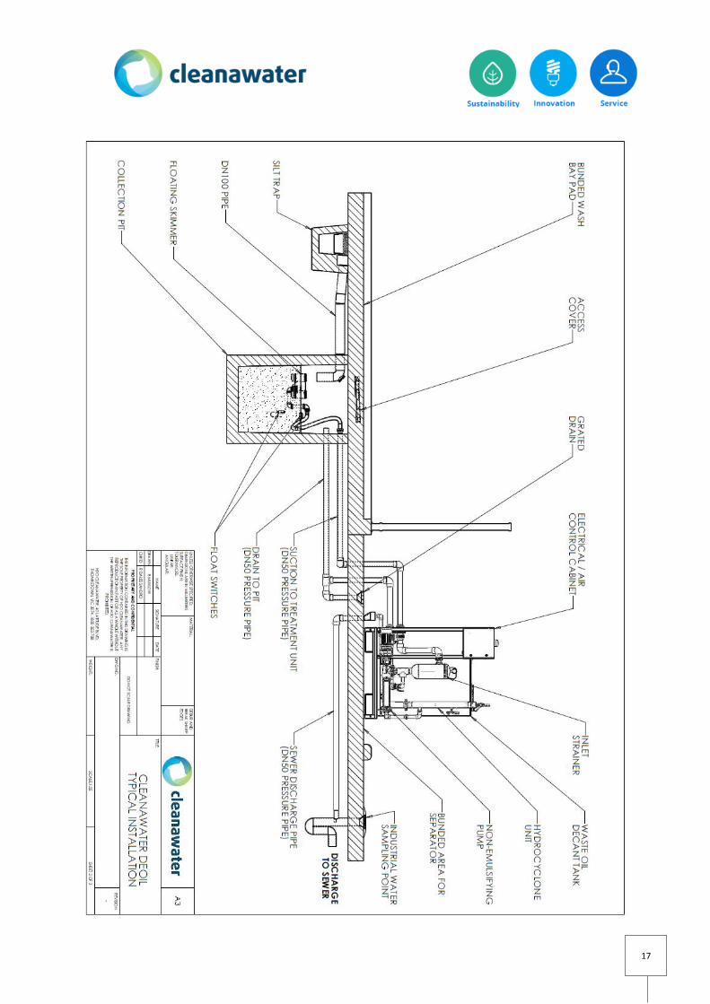
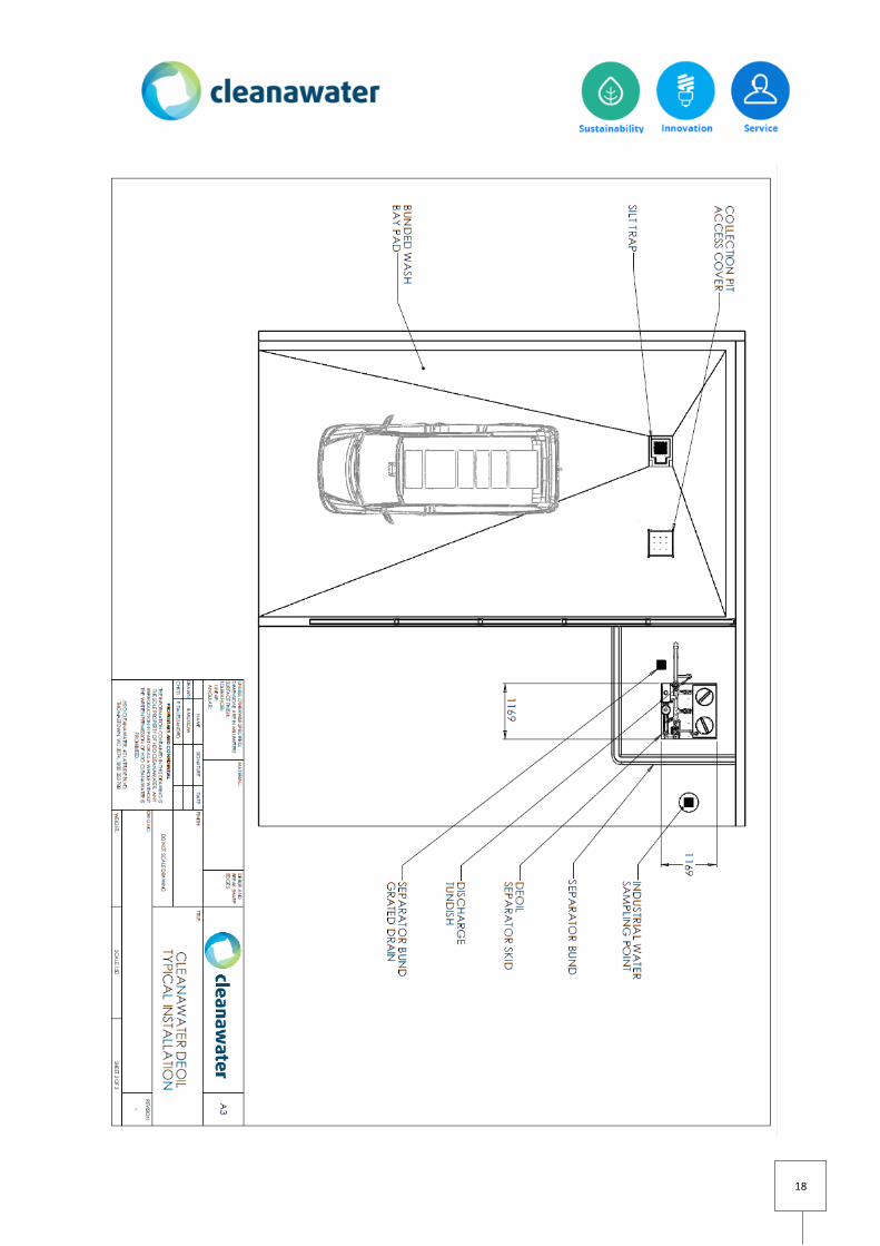
TYPICAL INSTALLATION SCHEMATIC
Cleanawater DEOIL hydrocyclone systems are factory assembled with minimal site connections to be made onsite.
Check with local authorities prior to installation of any pre-treatment device.
17
18
19
INSTALLATION INSTRUCTIONS
ALL PLUMBING MUST BE INSTALLED IN ACCORDANCE WITH AS/NZ 3500
Systems come supplied as skid mounted units with all plumbing connections within the skid perimeter completed
and factory commissioned. This reduces installation time and associated costs.
*-Note: At installation stage, all plumbing works must be completed by a licensed plumber. If electrical works are
required to be completed they must be completed by an electrician with relevant certifications.
Local water authorities should be contacted prior to installation to ensure local requirements have been met.
INSTALLATION PROCEDURES
STEP 1 – PREPARE AREA FOR INSTALLATION
Locate the oil separator in its operating position with sufficient service access clearance and the ability to operate
and service accordingly.
STEP 2 – SETTING UP
Place unit on a solid and even base. A level concrete slab is preferred. If the slab is uneven it is preferable to cement
slurry the surface and set the skid into the wet cement.
STEP 3 – SETTING UP
If it is required to tie down or fix the skid to a surface locate an adequate fixing points on the skid base. For
corrosive environments use galvanized fixing materials only.
Ensure that your foundation has sufficient strength to support the mass of the unit. Refer to the specifications for
operating weight of the system.
STEP 4 – CHECK FOR A LEVEL SURFACE
Ensure that the unit is level within 50 mm on both axes.
STEP 5 – INSTALL FLOATING OIL SKIMMER TO SUMP

20
Floating oil skimmers are designed to float on the surface of the sump. Attach supplied flexible suction hose to oil
skimmer outlet. This comes factory fitted with male to female threads for easy connection.
STEP 6 – INSTALL FLOATING OIL SKIMMER TO SUMP
Place skimmer in sump allowing enough hose slack to enable the skimmer to float unobstructed on the sump
surface. Ensure factory fitted hose float is approximately 1m from the floating skimmer, this will provide stability for
the floating system.
NOTE: CONFINED SPACE ENTRY PERMITS MAY BE REQUIRED TO COMPLETE THIS WORK.
STEP 7 – INSTALL FLOATING OIL SKIMMER TO SUMP
Connect loose end of floating skimmer hose to Inlet at oil separator skid location. Check connections to ensure they
are tight.
Note: Flexible suction hose may be cut if excess hose has been supplied.
STEP 8 – INSTALL FLOATING OIL SKIMMER TO SUMP
Observe floating skimmer operating level and adjust skimmer funnel level handle clockwise/anti clockwise to suit
ensuring the funnel is submersed 20-30mm under the water level. Check for any obstructions and clear accordingly.
Note: Trash or obstructions should be removed to avoid damaging pumps and/or hoses.
STEP 9 – COMPLETE PLUMBING CONNECTIONS
Refer to the typical schematic drawings located in this manual to complete remaining plumbing connections. Typical
remaining connections are as follows:
Waste Oil Decant Tank Reject return to sump with sufficient gravity fall
Separator Outlet –Discharge point
*- Refer to specification sheet for unit inlet/outlet sizes, check the manufacturer data sheet for pump inlet and
minimum diameter piping requirements to ensure pump warranty is not voided.
*- Note: Ensure local piping material standards have been met, any connections to sewer must be completed by a
licensed plumber.

21
* - Note: When system is operating if floating skimmer is bouncing on surface then pulsation dampeners may be
required to be installed to suction and discharge lines.
STEP 10 – PUMP PRIME & FILL WASTE OIL DECANT TANK WITH FRESH WATER
Complete the pump priming process in accordance with the attached manufacturer pump manual information.
Fill waste oil decant tank on installation to ensure the decant tank is ready for immediate operation.
NOTE: FAILING TO PRIME THE PUMP ON FIRST START MAY VOID PUMP WARRANTY.
STEP 11 – COMPLETE PLUMBING CONNECTIONS – DISCHARGE LINE
Plumb the oil separator outlet to discharge source. Barrel unions in the pipe to aid in servicing is recommended. All
discharge pipework must be in accordance with local regulations including any sampling points and tundishes.
Check your local plumbing regulations for pipe work requirements.
STEP 12 – CHECK PLUMBING CONNECTIONS – WASTE OIL DECANT TANK
Open inspection hatches to waste oil decant tank and ensure all internal factory fitted pipework has not been
damaged and all pipework and fittings are tight.
STEP 13 – COMPRESSED AIR CONNECTION
Refer to the installation diagram attached to this manual and connect compressed air source to pneumatic control
box. 10mm main airline connection is required. Ensure your air compressor is of adequate capacity to ensure the
system will run correctly.
STEP 14 – INSTALL PNUEMATIC FLOAT SWITCH TO SUMP / TANK
Fasten float switch box to sump side wall and set activation levels. Stainless steel rods have been supplied with your
package. In accordance with the diagram attached to this manual and the depth and capacity of your sump/tank cut
each rod to size to suit your application. Note: If using hand tools be sure to use adequate PPE protection.
Supplied float switches are to switch the pump/on automatically. Care is to be taken to ensure that the float travel is
not impeded in any way. The pumping range (switch on point) should be set approximately 500mm from the (switch
off point). This can be increased depending on the collection pit storage size.
For service and maintenance it is advised this box not be submersed in water in case of system failure.
Refer to supplied diagram at all times.

22
STEP 15 – COMPLETE PNEUMATIC CONNECTIONS – FLOAT SWITCHES
Connect pneumatic connections from float switch box to main pneumatic control box located on skid in accordance
with attached diagram in this manual. 6mm pilot air line connections are required.
Before switching on the system ensure the shut off valve within the pneumatic box is in the CLOSED position.
Refer to supplied connection diagram at all times.
STEP 16 – COMPLETE BOOTUP SEQUENCE PROCEDURES
Revisit all 15 installation steps listed above are completed
Ensure pump is primed prior to start up
If water is in the sump, switch the shutoff valve in the pneumatic box to the OPEN position
Check filter regulator reading and ensure reading is set to (DEOIL 3 - 7 bar) or (DEOIL5 – 6.5 bar)
Allow water to be pumped from the sump through the system and complete checks listed in the following
points
Check pressure of debris strainer is within the green zone
Check hydrocyclone underflow pressure is reading 170 kPa when pump is running
Check waste oil decant pressure is at zero
Check floating skimmer is buoyant, funnel is submersed and is not obstructed from floating on the surface
Check floating skimmer is not violently bouncing on the surface of the sump
Check sampling points are in the closed position
Check to ensure waste oil decant return line valve is in the open position
Check to ensure waste oil decant tank drain is in the closed position
Check to ensure filter drain manual valve is in the closed position
Check to confirm that reject is filling the waste oil decant tank
Check to confirm water is flowing into the cyclone via sampling point
Check to confirm that treated water is flowing out of the outlet via sampling point
STEP 17 – YOU ARE COMPLETE
Refer to operations and maintenance manual to ensure periodic maintenance on the system is completed.

23
FINAL INSTALLATION CHECKLIST
Refer to the checklist below to ensure your Cleanawater DEOILER oil separator has been setup correctly.
Note: This layout refers to a typical installation only. You may have specific installation instructions provided due to
an alternate layout or additional equipment installed for your waste water treatment solution.
Contact Cleanawater on 1800 353 788 for any questions related to installation and or operation of the system.
ITEM DESCRIPTION CHECKED
(Y/N)
Placement Unit is installed on flat ground
Unit has been fixed to floor surface
The system has adequate service access
Connections -
Plumbing
Plumbing connections are completed with all barrel unions tightened
including:
Sump/Tank/Skimmer outlet pump line to skid is connected
Waste oil decant tank reject line back to sump is connected
Check all factory connections between components which may have
become loose in transit including inside waste oil decant tank
Oil separator outlet to discharge source is connected
Pumps are primed in accordance with manufacturer instructions
Connections –
Pneumatic
Float switches set at correct on/off heights
Control panel is mounted and easily accessible
Control panel is plugged into main compressor air supply
Pump and control floats are connected back to control panel
Pump control panel has air source connected and filter regulator is
constantly reading (DEOIL 3 - 7 bar) or (DEOIL5 – 6.5 bar)
Oil Separator
operation
Pressure gauges are tightly fitted to liner sleeve
Debris strainer vacuum gauge reading is reading in the green safe zone
Underflow pressure to hydrocyclone is adjusted via gate valve to 170kPa
Floating skimmer and float switches are operating without obstruction
Waste oil decant tank is filled with fresh water
Oily water is entering the waste oil decant tank
Treated water is exiting through the treated water outlet

24
OPERATIONS & MAINTENANCE GUIDE
OPERATIONS
Once the unit is entered into operation, it is an automated process activated by the float switch in the collection pit
which controls water throughput the oil separator; discharge from the oil separator is via gravity into sewer/discharge
tank or to the next stage of treatment. Pump tanks if pumping to a discharge source can be supplied on request.
Maintenance is to be routinely completed to ensure that the system is operating to its designed efficiency.
Major components as follows should be checked during operational mode as listed below:
Operational Checkpoints – Air supply
Air supply is constant with filter regulator reading (DEOIL 3 - 7 bar) or (DEOIL5 – 6.5 bar)
All air connections are tight and float level triggers are operational
Operational Checkpoints - Floating Oil Skimmer
The skimmer is buoyant on all axis and the funnel is fully submersed below the water level
The skimmer is not violently bouncing on the surface when the pump is operating
The connection to the flexible suction line is tight
The hose float is approximately 1m from the skimmer head
Any debris is clear from the skimmer funnel
There are no obstructions in the pit to cause the skimmer to snag
Operational Checkpoints - Debris Strainer
The vacuum gauge reading is within normal operating limits (green zone)
The inlet and outlet connections are tight and no water leaks are present
Water flow is passing through to the oil separator

25
Operational Checkpoints - Hydrocyclone Oil Separator
The gauge reading on the cyclone under flow path is adjusted and within normal operating limits
Waste oil reject pressure reading is at zero
No water leaks are present at any connection points
All connections are tight with sampling points closed
When completing maintenance the hydrocylone liner is re installed correctly with all O rings in place
Water is discharging into the waste oil decant tank
Water is discharging via the treated water outlet
Operational Checkpoints - Waste Oil Decant Tank
The decant tank return line valve is open allowing for flow back to pit
Visually inspect oil levels within the decant tank and drain accordingly
Check internal pipework condition in decant tank via inspection hatches
Reject flow is not excessive
Reject flow is not at a dribble or intermittent
26
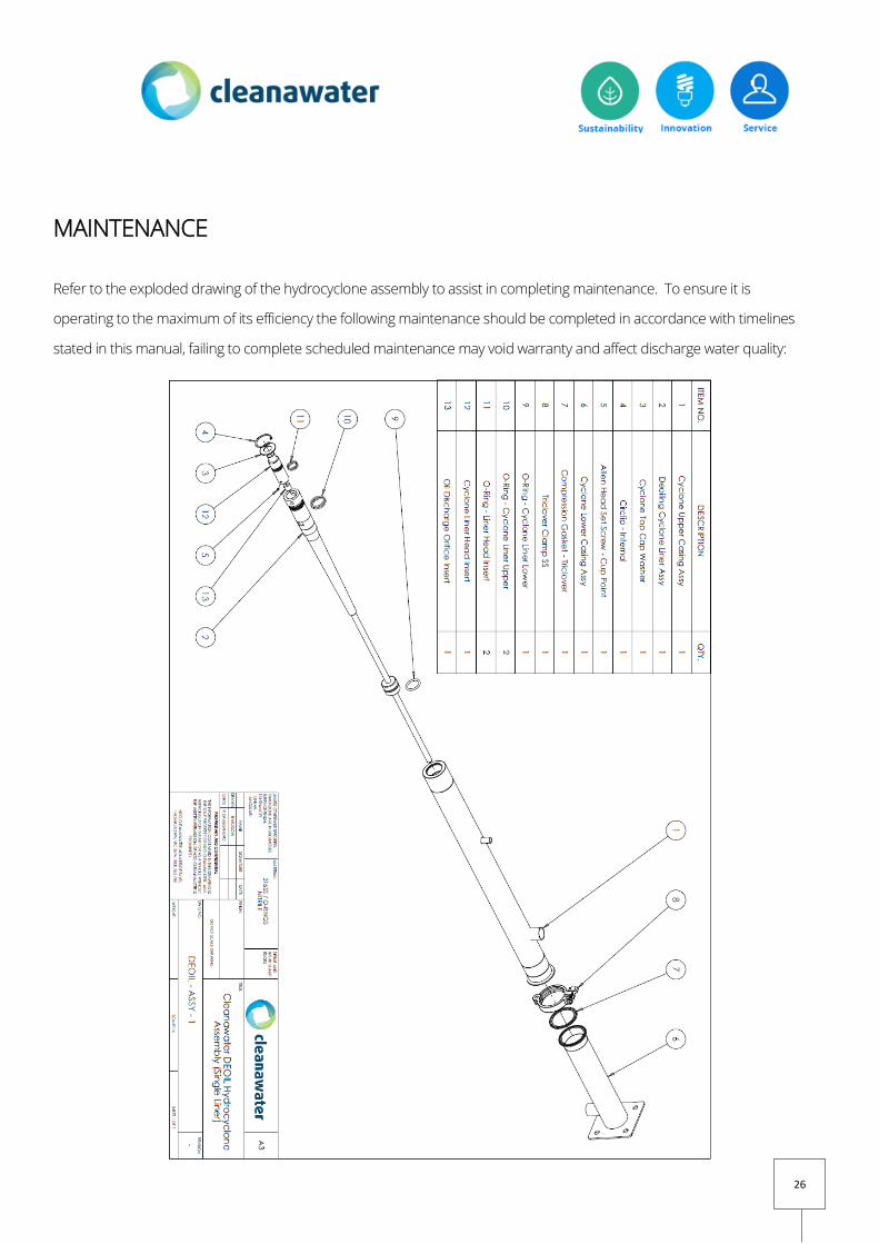
MAINTENANCE
Refer to the exploded drawing of the hydrocyclone assembly to assist in completing maintenance. To ensure it is
operating to the maximum of its efficiency the following maintenance should be completed in accordance with timelines
stated in this manual, failing to complete scheduled maintenance may void warranty and affect discharge water quality:
27
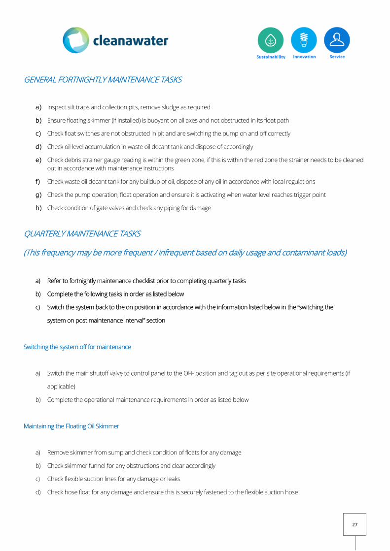
GENERAL FORTNIGHTLY MAINTENANCE TASKS
a) Inspect silt traps and collection pits, remove sludge as required
b) Ensure floating skimmer (if installed) is buoyant on all axes and not obstructed in its float path
c) Check float switches are not obstructed in pit and are switching the pump on and off correctly
d) Check oil level accumulation in waste oil decant tank and dispose of accordingly
e) Check debris strainer gauge reading is within the green zone, if this is within the red zone the strainer needs to be cleaned
out in accordance with maintenance instructions
f) Check waste oil decant tank for any buildup of oil, dispose of any oil in accordance with local regulations
g) Check the pump operation, float operation and ensure it is activating when water level reaches trigger point
h) Check condition of gate valves and check any piping for damage
QUARTERLY MAINTENANCE TASKS
(This frequency may be more frequent / infrequent based on daily usage and contaminant loads)
a) Refer to fortnightly maintenance checklist prior to completing quarterly tasks
b) Complete the following tasks in order as listed below
c) Switch the system back to the on position in accordance with the information listed below in the “switching the
system on post maintenance interval” section
Switching the system off for maintenance
a) Switch the main shutoff valve to control panel to the OFF position and tag out as per site operational requirements (if
applicable)
b) Complete the operational maintenance requirements in order as listed below
Maintaining the Floating Oil Skimmer
a) Remove skimmer from sump and check condition of floats for any damage
b) Check skimmer funnel for any obstructions and clear accordingly
c) Check flexible suction lines for any damage or leaks
d) Check hose float for any damage and ensure this is securely fastened to the flexible suction hose

28
Maintaining the Debris Strainer
a) Switch the system off ensuring no water is pumping through the system
b) Open the drain valve located adjacent to the strainer to drain the internals water in the strainer
c) Loosen clamps, remove cap from debris strainer and remove basket
d) Rinse basket with low pressure water to clear any sludge
e) Rinse debris strainer housing with fresh low pressure water to clear any sludge
f) Reinstate basket strainer into housing
g) Close the drain valve and fill strainer with fresh water
h) Reinstate strainer cap and clamps
Maintaining the Hydrocyclone Oil Separator (refer to exploded drawing for part ID on previous pages)
a) Clean debris strainer prior to removing cyclone from sleeve in accordance with instruction listed above
b) Undo barrel union connecting the waste oil outlet to waste oil decant tank
c) Undo barrel union on hydrocyclone inlet
d) Remove cir clip (Item 4) using cir clip pliers from deoiling cyclone liner assembly (item 2)
e) Remove cyclone liner head insert (item 12) from liner carefully by hand by pulling up
f) Undo tri clover clamp (item 8) from near the base of the cyclone liner joining the sleeve (care is to be taken that the
rubber seal is not misplaced or damaged)
g) Place the base of the exposed cyclone liner which is out of its sleeve down by holding it vertically on a soft ground
surface and place small amount of hand pressure to pop the cyclone out of the sleeve
h) Inspect the oil discharge orifice insert (item 13) for any blockage and clear with wire pick if required
i) Inspect the Liner head insert (item 12) for any blockage and clear with wire pick if required
j) Inspect the cyclone upper casing assembly (item 1) and lower casing assembly (item 6) for damage or internal
blockages and clear if required
k) Inspect all O rings (item 9.10,11) for damage and replace if required
l) Grease all O rings with rubber grease prior to reinserting cyclone back into liner assembly
m) Reinsert Oil Discharge Orifice Insert (item 13) into Cyclone liner head insert (item 12) ensuring they sit flush when
slotted back into place
n) Tighten set screw (item 5) inside of cyclone liner head insert (item 12) to hold Oil discharge orifice insert (item 13) in
situ
o) Insert cyclone liner head insert (item 12) into the deoiling cyclone liner assembly (item 2)

29
p) Inspect seal on O rings (item 9, 10, 11) for wear or damage and ensure they are greased
q) Insert assembled deoiling cyclone liner assembly (item 2) into cyclone upper lining assembly (item 1)
r) Fit cyclone top cap washer (item 3) into cyclone upper lining (item 1)
s) Using cir clip pliers install cir clip (item 4) into cyclone upper casing assembly (item 1) to hold cyclone liner head insert
(item 12) in situ
t) Apply rubber grease to compression gasket – triclover (item 7)
u) Sit compression gasket – triclover (item 7) onto triclover fitting of cyclone lower casing assembly (item 7)
v) Fit assembled hydrocyclone in cyclone upper casing assembly (item 1) onto triclover gasket onto cyclone lower casing
assembly (item 7)
w) Install triclover clamp (item 8) to hold in cyclone upper casing assembly (item 1) and cyclone lower casing assembly
(item 7) together and tighten triclover clamp (item 8)
x) Reconnect and tighten connection to waste oil decant tank line, ensure o ring is inserted
y) Reconnect and tighten connection to hydrocyclone inlet line to sleeve
Maintaining the Waste Oil Decant Tank
a) Inspect levels of waste oil in decant tank and have oil sucked out of tank by authorized waste oil removal contractor
b) Open service drain at the base of the waste oil decant tank and drain all water back to the pit
c) Rinse tank walls with fresh water, refill tank with fresh water and inspect condition of internal plumbing
d) Close service drain to decant tank
e) Inspect external tank walls and inspection hatches for damage
Switching the system on post maintenance interval
a) If any operational concerns or questions arise or spares need to be ordered whilst completing maintenance contact
Cleanawater on 1800 353 788 prior to entering the system back into operation
b) Switch the main shutoff valve in the control panel to the ON position
c) Check filter regulator reading is set to (DEOIL 3 - 7 bar) or (DEOIL5 – 6.5 bar) and this reading is constant
d) Check waste oil decant tank is slowly refilling with waste oil water reject when the pump is operating and pumping
fluid
e) Check that debris strainer gauge is reading within green safe zone range
f) Check that manual drain valves where applicable are returned to the closed position
g) Check the waste oil drain line service valve is in the closed position

30
h) The system is now back in normal operation
ANNUAL MAINTENANCE (this may be more frequent or infrequent based on daily usage and
contaminant loads)
a) Complete fortnightly checks as per normal maintenance recommendation
b) Complete quarterly maintenance as per schedule
c) Check pump component condition in accordance with manufacturer recommendations
d) Check condition of all system components
e) Check and retighten all connections as tighten as required
SERVICING HELPDESK
Cleanawater provide master care programmed scheduled service packages on request.
If you prefer for Cleanawater to maintain your treatment system or have any servicing related questions helpdesk engineers
are available to take your call 24 hours per day, 7 days per week:
Business Hours Telephone : 1800 353 788
After Hours Telephone (and weekends) + 61 3 9188 3679
Email: [email protected]

31
WARRANTY TERMS
Pump & Pneumatic Component Warranty
Manufacturer’s warranty is 12 months from the date of sale unless specified.
Oil Separator, Oil Skimmer and Stainless Steel Component Warranty
The Cleanawater deoiler system is supplied with a 5 year perforation warranty period. Fitted skid mounted
components may include 304 and/or 316 stainless steel components ideally suited for non-corrosive environments.
If any corrosive elements exist contact Cleanawater to discuss required upgrades.
Waste Oil Decant Tank
Manufacturer’s warranty is 5 years from the date of sale unless specified. Waste oil tank is UV stabilized to allow for
installation in external environments.
Other components
All other components supplied with the oil separator are sold with a 12 month warranty from the date of sale unless
specified.
Compliance Plates
Each Cleanawater oil separator has an identification plate, attached to the outside of the supplied control panel side wall.
Plate material is aluminium foil with overall dimensions of 120mm x 50mm.
32
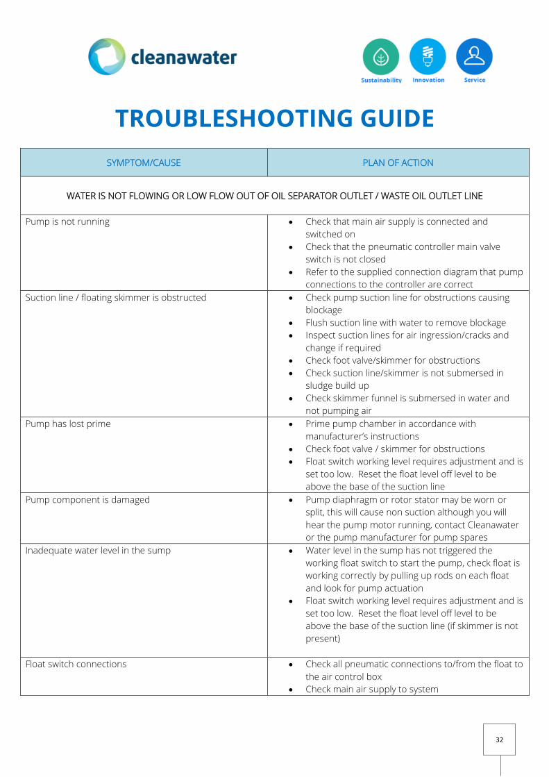
TROUBLESHOOTING GUIDE
SYMPTOM/CAUSE PLAN OF ACTION
WATER IS NOT FLOWING OR LOW FLOW OUT OF OIL SEPARATOR OUTLET / WASTE OIL OUTLET LINE
Pump is not running Check that main air supply is connected and
switched on
Check that the pneumatic controller main valve
switch is not closed
Refer to the supplied connection diagram that pump
connections to the controller are correct
Suction line / floating skimmer is obstructed Check pump suction line for obstructions causing
blockage
Flush suction line with water to remove blockage
Inspect suction lines for air ingression/cracks and
change if required
Check foot valve/skimmer for obstructions
Check suction line/skimmer is not submersed in
sludge build up
Check skimmer funnel is submersed in water and
not pumping air
Pump has lost prime Prime pump chamber in accordance with
manufacturer’s instructions
Check foot valve / skimmer for obstructions
Float switch working level requires adjustment and is
set too low. Reset the float level off level to be
above the base of the suction line
Pump component is damaged Pump diaphragm or rotor stator may be worn or
split, this will cause non suction although you will
hear the pump motor running, contact Cleanawater
or the pump manufacturer for pump spares
Inadequate water level in the sump Water level in the sump has not triggered the
working float switch to start the pump, check float is
working correctly by pulling up rods on each float
and look for pump actuation
Float switch working level requires adjustment and is
set too low. Reset the float level off level to be
above the base of the suction line (if skimmer is not
present)
Float switch connections Check all pneumatic connections to/from the float to
the air control box
Check main air supply to system

33
Outlet / Orifice blockage or pressure adjustment Check waste oil reject orifice in accordance with
maintenance manual (system shut down procedure
is to be completed to check this item)
Ensure treated water outlet valve is adjusted
correctly
LOW / HIGH / ERRATIC WATER FLOW THROUGH SYSTEM
Check pump operation to ensure pump is switching
on/off correctly.
Refer to the maintenance information guide and
clean the debris strainer immediately (the system
requires shut down to complete this action)
Probe pit for sludge levels and dispose of
accumulated sludge accordingly
Check pit for floating debris and obstructions
Suction Line is obstructed Check pump suction line for obstructions causing
blockage
Flush suction line with water to remove blockage
Inspect suction lines for air ingression/cracks and
change if required
Check foot valve/skimmer for obstructions
Check suction line/skimmer is not submersed in
sludge build up
Check skimmer funnel is submersed in water and
not pumping air
Pump flow is low Strainer is blocked causing low flow rate to process
through the system, clear accordingly
Air regulator in main air control box is set too low
and requires adjustment to increase BPM of pump
Check all air supply filters for blockages, leaks or
restrictions
Check main air compressor supply for faults
Check capacity of air compressor is suitable for
application
Pump operation is not steady Strainer is blocked causing low flow rate to process
through the system, clear accordingly
Check suction line and floating skimmer funnel for
blockages and ingression of sludge or trash
Check skimmer funnel is submersed in water and
not pumping air
Check for leaks in system components, pay
particular attention to seals, clamps, barrel unions
and sampling points left in the open position
Pump flow is high Air regulator in main air control box is set too high
and requires adjustment to decrease BPM of pump
PUMP IS RUNNING BUT NO WATER IS FLOWING INTO THE OIL SEPARATOR
Suction line is obstructed Check pump suction line for obstructions causing
blockage

34
Flush suction line with water to remove blockage
Inspect suction lines for air ingression/cracks and
change if required
Check foot valve/skimmer for obstructions
Check suction line/skimmer is not submersed in
sludge build up
Check skimmer funnel is submersed in water and
not pumping air
Pump component is damaged Pump diaphragm or rotor stator may be worn, this
will cause non suction although you will hear the
pump motor running, contact Cleanawater or the
pump manufacturer for pump spares
THERE IS NO WATER IN THE WASTE OIL DECANT TANK
Check hydrocyclone components Open inlet sampling point to hydrocyclone to
ascertain if water is flowing through the sleeve
Check waste oil outlet orifice is not blocked
Check pressure regulation valve is adjusted
accordingly to enable efficient waste oil discharge
Check debris strainer is operating within acceptable
limits
Check fixed plumbing line for internal pipe blockage
Check waste oil decant tank for sludge, excessive
sludge may be blocking the inlet to tank
THERE ARE HIGH AMOUNTS OF WATER FLOWING INTO THE WASTE OIL DECANT TANK
Check hydrocyclone components Open inlet sampling point to hydrocyclone to
ascertain if water levels of water are flowing through
the sleeve
Check pressure regulation valve to treated water
outlet is adjusted accordingly to enable efficient
waste oil discharge
Check that waste oil reject assembly components
are correctly fitted including reject orifice fitting and
o-ring
Check discharge pipework via sampling point for
blockages and clear accordingly
THE SYSTEM WILL NOT SWITCH ON/OFF
No air supply to pump The pump air supply may have faults or the main
shut off valve is closed
Check main air supply and pneumatic connections
to/from the main air control panel and float switch

35
Float switch is stuck Check float switch levels to ensure they are not
obstructed, flick the rods up by hand to ensure the
pump switches on and off accordingly
THERE IS OIL PRESENT IN THE DISCHARGE
Oil spill has occurred or excessive load of oil ingression Oil spillage event or disproportionate loads of oil is
pumping through the system, attend to the spillage
as soon as possible
If excessive oil loads exists, contact Cleanawater for
to provide you with an system upgrade kit
Contamination of waste water stream Ensure that quick break, biodegradable detergents
and degreasers are used with the oil separator,
mixture with other detergents and degreasers or
other contaminants may affect the waste water
stream and discharge results
Waste oil decant tank is full Check oil levels in the waste oil decant tank, dispose
of oils accordingly
Discharge blockage Blockage may be present in the underflow causing
discharge quality problems
High pump flow Air regulator in main air control box is set too high
and requires adjustment to decrease BPM of pump
THERE IS A SMELL COMING FROM THE PIT OR THE OIL SEPARATOR SYSTEM
Pump is not running Check pump operation to ensure pump is switching
on/off correctly.
Sludge build up in pit or separator Check sump levels for build-up of sludge and have
pit pumped out regularly
Oil separator requires a service in accordance with
operations and maintenance manual
Stagnant water Run fresh water into the pit to flush existing
contents and run the oil separator feed pump to
clear stagnant water.

36
CLEANAWATER TERMS & CONDITIONS

37

38

39

40
PLEASE REFER TO YOUR WIRING DIAGRAM AND
PUMP MANUAL FOR OTHER IMPORTANT
PACKAGE INFORMATION.