installation rules
DESCRIPTION
Installation Rules. Introduction. In Leonardo Evolution units, the air flow can be upwards or downwards. - PowerPoint PPT PresentationTRANSCRIPT

1
2
Installation RulesInstallation Rules

3
Introduction
Downflow units (with downwards air discharge) handle large volumes of air which are distributed uniformly into the environment by means of a void under a raised access floor. The air enters the unit directly from the environment, or through a ventilated or false ceiling.
In Leonardo Evolution units, the air flow can be upwards or downwards.
Upflow units (with upwards air discharge) are designed to distribute the air through a system of ducts or by means of a false ceiling. Air intake is usually through the front of the unit, but versions are also available with air intake through the rear or the base of the unit.

4
Leonardo Evolution units must be installed internally and protected
from adverse conditions.
Installation Area
WARNING! If the surface where the unit is placed is not even and horizontal, there is a risk of an overflow from the condensation tray; a maximum height difference of 5mm between the ends of the unit is allowed.
The area of installation must have the following characteristics:• to facilitate maintenance, leave a clearance (distance D) of at least 700mm free in front of the unit. Check that the air intake and discharge
connections are not blocked in any way, not even partially;• the electrical energy distribution system must respect CEI standards, suitable for the characteristics of the unit;• a cold water distribution plant (if a humidifier is going to be installed);• piping lines for connection to the condensing unit;• external air outlet (if a fresh air intake is going to be installed);• drainage system.• a horizontal and even floor;

5
Positioning the unit
The units are predisposed for installation on raised access flooring using mounting frames or appropriate floor stands.
The frame enables the installation of the unit before the raised floor is installed, increases the noise and vibration absorption and the facilitation of connecting pipes and cables.
The upflow models (upwards air flow) with rear or frontal air intake may be installed without using the mounting frame.
To install the unit on raised flooring using the mounting frame, carry out the following procedures:• a flexible seal at least 5 mm thick should be fitted between the raised floor panels
and the mounting frame which should also be isolated from the metallic floor structure;• position the unit of the mounting frame and fix it using the M8 screw inserts found on the base of the unit.
6
Refrigerant connections
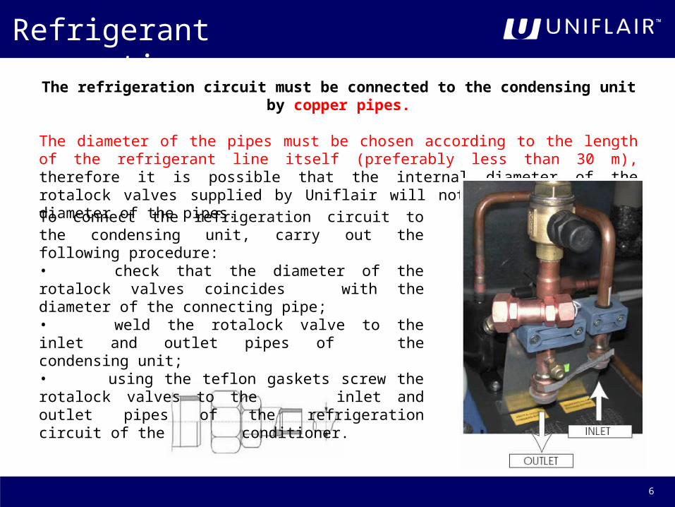
The refrigeration circuit must be connected to the condensing unit by copper pipes.
The diameter of the pipes must be chosen according to the length of the refrigerant line itself (preferably less than 30 m), therefore it is possible that the internal diameter of the rotalock valves supplied by Uniflair will not coincide with the diameter of the pipes.
To connect the refrigeration circuit to the condensing unit, carry out the following procedure:• check that the diameter of the rotalock valves coincides with the diameter of the connecting pipe;• weld the rotalock valve to the inlet and outlet pipes of the condensing unit;• using the teflon gaskets screw the rotalock valves to the inlet and outlet pipes of therefrigeration circuit of the conditioner.

7
Refrigerant Line Sizing
WARNING! The pipes must always be protected from the sun.
The discharge line must be sized in order to guarantee the flow of oil, in particular when operating at partial load, avoiding the return of the condensate refrigerant to the head of the compressor and prevent excessive vibration and noise due to the pulsations of hot gas, vibrations of the compressor, or both.
The loss of load along the discharge line causes an increase in the condensing temperature and therefore a decrease in the cooling capacity of the conditioner; each percentage point of decrease in cooling capacity corresponds to a decrease of 1°C of the maximum operating temperature.
Even if it would be preferable to have low losses of the load along the line, an oversized discharge line is necessary to reduce the speed of the refrigerant so that it does not provoke a reduction of the oil flow.Moreover, when the machine uses more compressors for the cooling circuit, the discharge line must transport the oil at all operating levels.

8
Refrigerant Line Sizing

9
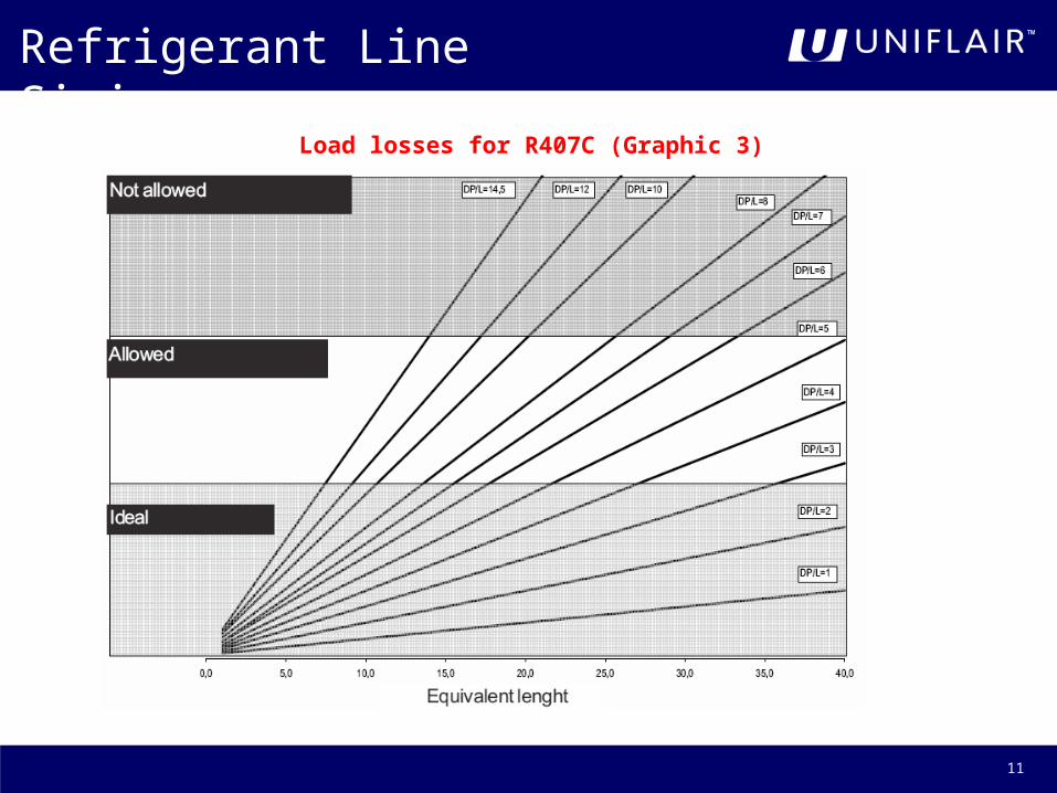
The minimum diameters needed to guarantee the flow of oil can be found in the following charts for the horizontal and vertical lines; these diagrams depends on the type of refrigerant.
Discharge horizontal line sizing for R407C (Graphic 1)
Refrigerant Line Sizing

10
Discharge vertical line sizing for R407C (Graphic 2)
Refrigerant Line Sizing
11
Load losses for R407C (Graphic 3)
Refrigerant Line Sizing

12
Refrigerant Line Sizing
13
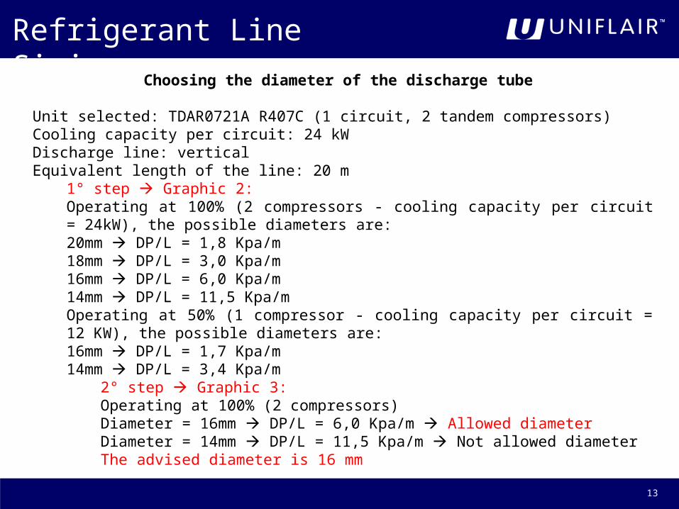
Choosing the diameter of the discharge tube
Unit selected: TDAR0721A R407C (1 circuit, 2 tandem compressors)Cooling capacity per circuit: 24 kWDischarge line: verticalEquivalent length of the line: 20 m
1° step Graphic 2:Operating at 100% (2 compressors - cooling capacity per circuit = 24kW), the possible diameters are:20mm DP/L = 1,8 Kpa/m18mm DP/L = 3,0 Kpa/m16mm DP/L = 6,0 Kpa/m14mm DP/L = 11,5 Kpa/mOperating at 50% (1 compressor - cooling capacity per circuit = 12 KW), the possible diameters are:16mm DP/L = 1,7 Kpa/m14mm DP/L = 3,4 Kpa/m
2° step Graphic 3:Operating at 100% (2 compressors)Diameter = 16mm DP/L = 6,0 Kpa/m Allowed diameter Diameter = 14mm DP/L = 11,5 Kpa/m Not allowed diameterThe advised diameter is 16 mm
Refrigerant Line Sizing

14
Choosing the diameter of the liquid line
To avoid gas development inside the line and to ensure the adequate pressure is reached inside the laminating unit, the liquid line must be correctly dimensioned. Generally, the systems are designed so that pressure loss along the line causes a variation of the saturation temperature between 0,5°C and 1°C.
WARNING! During the installation of the cooling unit, a check valve should be fitted on the liquid line between the inner unit and the external condenser, to avoid malfunctioning and to protect the compressor from unwanted liquid migration during start- up.
Refrigerant Line Sizing

15
Line Sizing Program
Refrigerant Line Sizing

16
Hydraulic Connections
Direct connection to the drains of the building
Connect the drainage tube of the unit to the drains of the building using a rubber or plastic tube with an internal diameter of 25 mm.The external drainage tube must be siphoned in order to avoid unpleasant odours. Maintain a minimum slope of 1% downstream the siphon.

17
Hydraulic Connections
Connection to the humidifier (optional) and to the drains of the building
WARNING! The water discharged from the humidifier is at a very high temperature. The drainage tube has to withstand high temperatures (at least 100°C) and must be kept away from electrical cables.
Connect the drainage tube of the unit to the collection tray (U4) of the humidifier.Connect the drainage tube of the humidifier (U7) to the drains of the building using a rubber or plastic tube, which is resistant to high temperatures (minimum 100 °C) with an internaldiameter of 22 mm.
The external drainage tube must be siphoned to avoid unpleasant odours and an overflow of the water from the tray of the humidifier. Maintain a minimum slope of 1% downstream of the siphon.

18
Hydraulic Connections
Connection to the gas drain
The cooling circuit is equipped with a safety valve for the discharge of the refrigerant gas.The intervention of the valve allows the discharge of the refrigerant fluid, possibly at high temperatures; in the case of installation in a closed environment, where the risk of causing damage to people nearby exists, a conveying tube must be used from the discharge to outside the room.Where it is not possible to install a conveying tube it is good practice to create adequate aeration of the environment, and indicate, through specific signs, the presence of the drain.
Also check that the discharge of the valve does not take place behind the electrical boards or electrical equipment.
19
Hydraulic Connections
Connection for water cooled units
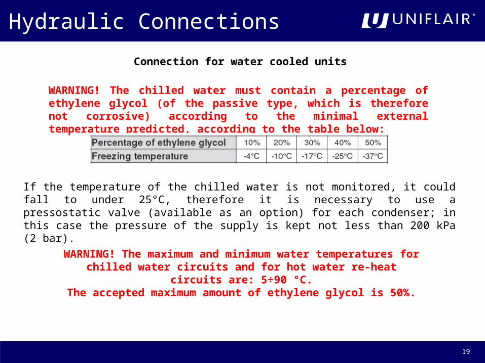
WARNING! The chilled water must contain a percentage of ethylene glycol (of the passive type, which is therefore not corrosive) according to the minimal external temperature predicted, according to the table below:
If the temperature of the chilled water is not monitored, it could fall to under 25°C, therefore it is necessary to use a pressostatic valve (available as an option) for each condenser; in this case the pressure of the supply is kept not less than 200 kPa (2 bar).
WARNING! The maximum and minimum water temperatures for chilled water circuits and for hot water re-heat circuits are: 5÷90 °C.The accepted maximum amount of ethylene glycol is 50%.
20
Hydraulic Connections
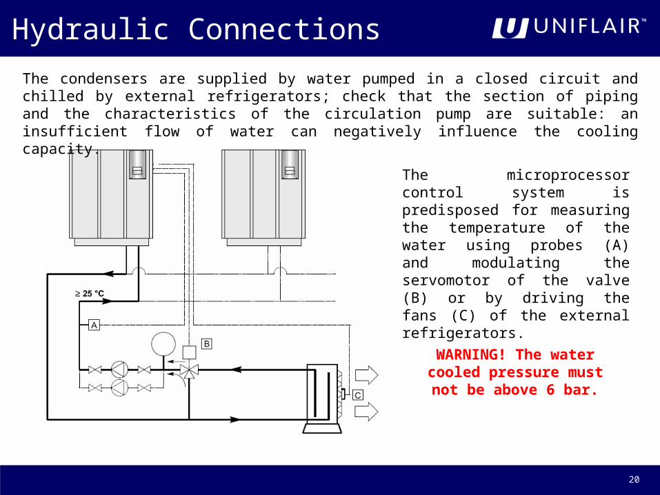
The microprocessor control system is predisposed for measuring the temperature of the water using probes (A) and modulating the servomotor of the valve (B) or by driving the fans (C) of the external refrigerators.
The condensers are supplied by water pumped in a closed circuit and chilled by external refrigerators; check that the section of piping and the characteristics of the circulation pump are suitable: an insufficient flow of water can negatively influence the cooling capacity.
WARNING! The water cooled pressure must not
be above 6 bar.

21
Hydraulic Connections
Table of condenser fitting dimensions
Once the connections have been made to the hydraulic circuit, the system can be filled.

22
Electrical Connections
WARNING! Electrical lines must be established
in full respect of CEI standards.
WARNING! Before establishing the electrical connection,
make sure that the power supply is off. Also ensure that it is not possible to reconnect the power during the operation.
WARNING! The power supply voltage must be ±10%.

23
Electrical Connections
To carry out the electrical connections of the machine to the power supply, carry out the following procedures:
• use suitable equipment to check the efficiency of the grounding system;• check that the voltage and network frequency correspond to those of the machine (see identification label);• open the door of the electrical panel;• remove the plastic screen of the electrical panel using a star screwdriver;

24
Electrical Connections
• pass the cables inside using the power supply cable inlet D7A which connects to the main switch D5;
• refer to the wiring diagram and connect the cable to the main switch D5.

25
Electrical Connections
To connect the auxiliary connections to the terminal board, carry out the following procedure:• pass the cables through the power supply cable inlet D7B;• refer to the wiring diagram and carry out the connection to the terminal board.
DIGITAL CONFIGURABLE INPUTS:
Terminal board 51-20- User- Remote ON-OFF- Flooding sensor (SAS)
Terminal board 52-20- User- Remote ON-OFF- Fire-smoke sensor (SFF)
Terminal board 50-20- User- Remote ON-OFF- Tools (ATA-BTA-AUA-BUA)
26
Start-Up of the Unit
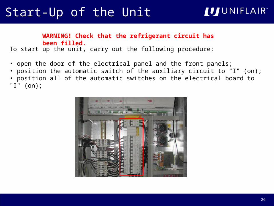
WARNING! Check that the refrigerant circuit has been filled.
To start up the unit, carry out the following procedure:
• open the door of the electrical panel and the front panels;• position the automatic switch of the auxiliary circuit to "I" (on);• position all of the automatic switches on the electrical board to "I" (on);
27
Start-Up of the Unit
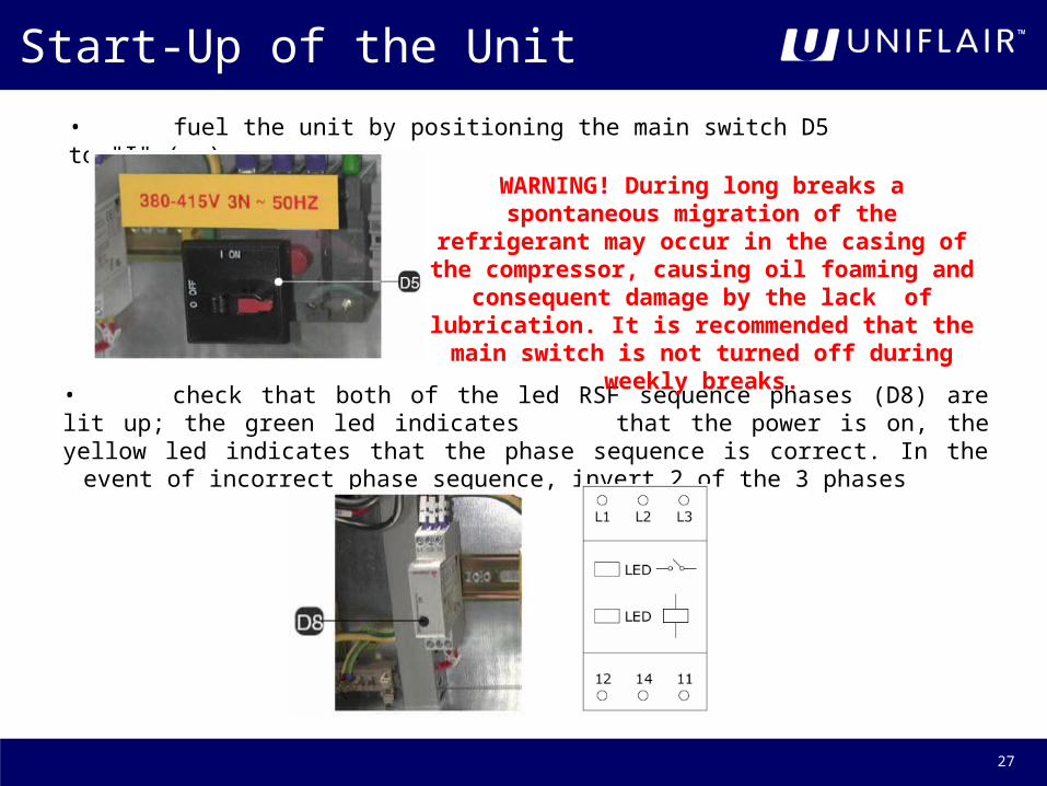
• fuel the unit by positioning the main switch D5 to "I" (on);
• check that both of the led RSF sequence phases (D8) are lit up; the green led indicates that the power is on, the yellow led indicates that the phase sequence is correct. In the event of incorrect phase sequence, invert 2 of the 3 phases
WARNING! During long breaks aspontaneous migration of the refrigerant may
occur in the casing of the compressor, causing oil foaming and consequent damage by the lack of lubrication. It is recommended that the main switch is not turned off during weekly breaks.

28
Start-Up of the Unit
• wait at least 12 hours before start up so that the oil in the compressors warms up enough;• open the shut off valves (I5) of the refrigerating circuits;
• check that the remote condensers are powered (on air cooled models);• check that the external dry coolers are powered and check the presence of the water flow
for condensation (on water cooled models);• check that the tracts of siphoned corrugated pipe, both internal and external to the conditioner, have been filled with water in the installation phase;• close the door and the front panels;

29
Start-Up of the Unit
• press the ENTER key (A6) of the user terminal; a sliding bar and a ventilator icon will appear on the display;
• if an alarm is indicated, consult the user interface manual UG40;

30