installation thermostatic mixers taps … · sensor protector: this black-out lens cover should...
TRANSCRIPT
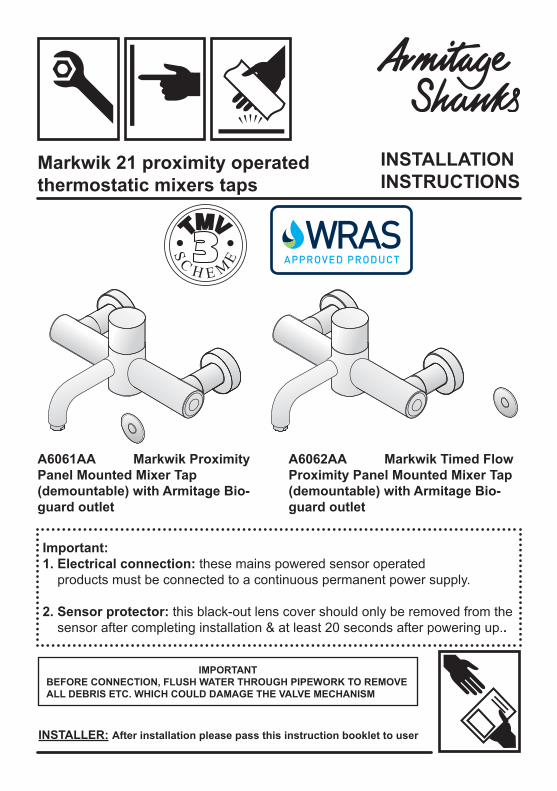
A6061AA Markwik Proximity Panel Mounted Mixer Tap(demountable) with Armitage Bio-guard outlet
Important:1. Electrical connection: these mains powered sensor operated products must be connected to a continuous permanent power supply.
2. Sensor protector: this black-out lens cover should only be removed from the sensor after completing installation & at least 20 seconds after powering up..
A6062AA Markwik Timed Flow Proximity Panel Mounted Mixer Tap (demountable) with Armitage Bio-guard outlet
Markwik 21 proximity operated thermostatic mixers taps
INSTALLER: After installation please pass this instruction booklet to user
IMPORTANTBEFORE CONNECTION, FLUSH WATER THROUGH PIPEWORK TO REMOVEALL DEBRIS ETC. WHICH COULD DAMAGE THE VALVE MECHANISM
INSTALLATIONINSTRUCTIONS

2
The fittings covered by this installation and maintenance instructionshould be installed in accordance with the water regulationspublished in 1999*, therefore Armitage Shanks would stronglyrecommend that these fittings are installed by a professional installer
*A guide to the Water Supply (Water Fittings) Regulations 1999 and the Water Byelaws 2000, Scotland is published by WRAS (Water Regulations Advisory Scheme) Fern Close, Pen-y-Fan Industrial Estate, Oakdale, Newport, NP11 3EH. ISBN 0-9539708-0-9
2 DESCRIPTION
This manual covers the Markwik range of proximity operated, panel mounted, thermostaticallycontrolled mixers. These are designed to provide water at a preset temperature for hand washing.The proximity controls allow operation of the flow without the user having to touch the mixer.
These products are fitted with an Armitage Bioguard outlet which reduces the opportunity for bio film attachment and is lined with anti-microbial copper.
A hygiene flush (automatic) is an important optional feature of these products which can be enabled by the installer or maintenance staff using the optional remote programming unit. The hygiene flush is used to combat periods of low usage of the product. The program monitors and permits the fitting to be run automatically if it hasn’t been used for a set time period. This feature ensures regular movement of water preventing stagnation, thus combating bio film growth and bacteria colonisation. See section 12.5 for more details.
Two models are covered.The Proximity Mixer, where flow occurs only while the user’s hands are in the detection zone.The Timed Flow Mixer, where flow starts when the user’s hand enters the detection zone and shuts offafter a preset time. The preset time can be adjusted. Traditionally the sensor is mounted to the rightof the fitting, but it can be mounted to the left if necessary.
They are both intended to be installed on duct panel walls.The panel thickness should be in the range 13 - 27 mm. Two holes, of diameter 30mm nominal andone at 35mm nominal, will need to be cut in the panel at centres defined in Figures 1 & 2
The hot side of the mixer is insulated to ensure the body surface is maintained at a safe temperaturewhen the fitting is in operation. These mixing valves are supplied complete with integral isolating valves, strainers, check valves and flow regulators and are provided with a facility for thermal disinfecting of the cold inlet side and mixed water outlet
In response to the new requirements of HTM 04-01 Addendum, the design ofMarkwik mixers has been enhanced to permit easy demounting of themixer from the inlets..
Avoid using heat for soldering near the mixer inletsto prevent damage to internal components.
FITTINGS COVERED
Description
A6061AA Markwik Proximity Thermostatic Panel Mounted Mixer with Armitage Bioguard outlet
A6062AA Markwik Timed Flow, Proximity Operated Thermostatic Panel Mounted Mixer with Armitage Bioguard outlet
3
3 DIMENSIONS
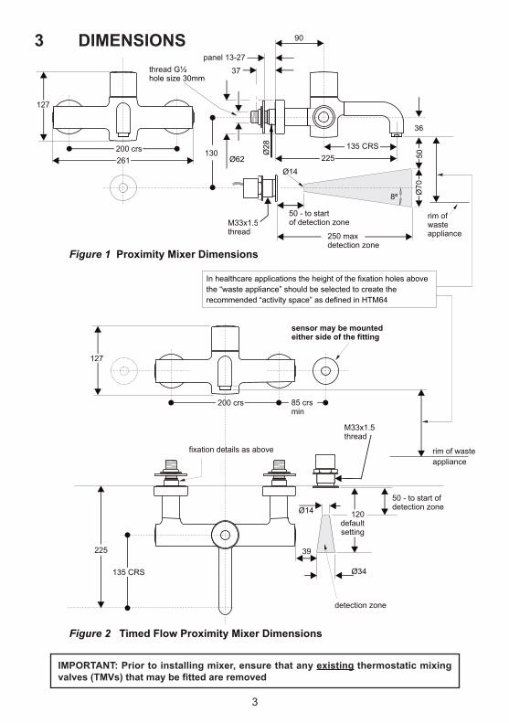
Figure 1 Proximity Mixer Dimensions
Figure 2 Timed Flow Proximity Mixer Dimensions
In healthcare applications the height of the fixation holes above the “waste appliance” should be selected to create the recommended “activity space” as defined in HTM64
37
panel 13-27
225135 CRS
90
36
200 crs
200 crs
261
127
127
Ø62
Ø28
Ø70
8º
Ø14
Ø14
50 - to startof detection zone
50 - to start ofdetection zone
250 maxdetection zone
130
thread G½ hole size 30mm
85 crsmin
Ø34
39
120 default setting
detection zone
50
M33x1.5thread
M33x1.5thread
135 CRS
225
fixation details as above
rim ofwasteappliance
rim of wasteappliance
sensor may be mountedeither side of the fitting
IMPORTANT: Prior to installing mixer, ensure that any existing thermostatic mixing valves (TMVs) that may be fitted are removed
4
In accordance with the NHS model engineering specifications DO8 this valve has approval forthe following applications:- High Pressure HP- -WE Low Pressure LP- -WE
For this type of application the following supply conditions must apply:
Operating pressure range: High Pressure Low Pressure
Maximum static pressure 10 bar 10 bar
Flow pressure hot and cold 1 to 5.0 bar 0.2 to 1.0 bar
Hot supply temperature 55 to 65 °C 55 to 65 °C
Cold supply temperature 5 to 20 °C 5 to 20 °C
4.3 Healthcare Establishments
Note:Fittings operating outside these conditions cannot be guaranteed by the scheme to operate as TMV3.
*52°C absolute minimum can be used but not recommended
Table 1 Supply conditions for healthcare establishments
Effectively this means:Differential between HOT and COLD inlet temperatures ( ∆t ) must be 32C° min and 60C° maxDifferential between HOT inlet temperature and MIXED temperature ( ∆t ) must be 11C° absolute mini-mum but > 14C° preferredSee 9.3 Audit checks on TMV’s.
4.1 Introduction
4.2 Supply Pressure Requirements
This proximity operated thermostatically controlled mixers are manufactured to the highest standards and have approval to TMV3 which permits it to be installed in healthcare establishments such as hospi-tals, nursing homes and residential care homes. When installed in healthcare establishments the supply conditions detailed in Table 1 must be observed and the commissioning and servicing requirements detailed on section 9 & 10 must be followed.
For other installations this is not a requirement.
This mixers are designed to be installed on all types of plumbing systems.
Hot and cold water supply pressures should be reasonably balanced, however, the mixer will function within specification on unequal pressures up to 5 :1.
The mixers has integral isolating valves which permit servicing of the strainer, flow regulator & thermo-static cartridge. They are also used for thermal disinfection.
The minimum pressure for the correct thermal operation is 0.2 bar. However, in order to achieve an ac-ceptable flow performance at very low pressures it may be necessary to remove the flow regulators (10). IMPORTANT: DO NOT REMOVE check valves fitted inside the inlet tails (19) - see figure 27.
4 WATER SUPPLY CONDITIONS

5
5 INSTALLATION: FIxATION
Figure 3 Proximity mixer installation panel mounting (RH inlet cut away for clarity)
200 mm
130
mm
Ø30 nominal
Ø35 nominal
backnut
slipwasher
slip washer
wall panelseal
seal
reversible backnut
proximity sensor
slipwasher
reversiblebacknut
backnut
slipwasher
Figure 4 Timed Flow mixer installation - panel mounting
200 mm85 mmminleft orright
Ø30nominal
Ø35 nominal
wallplateshroud
seal
sealtimed flow
sensor
wallpanel
These mixers are designed to be panel mounted on a duct wall of maximum panel thickness 27mm. For thicker panels the rear of the panel will require counter bores of 62mm or greater around the fixa-tion holes.
Cut two holes of 30mm diameter, horizontally aligned to 200mm centres in the wall.(See figure 1 for height positioning of the fitting body over a “waste appliance”)
The sensor will require a hole of 35mm positioned as indicated in either fig1 or fig2.
Loosen the chrome shrouds and insert the fitting as shown above with the wall plates and seals to the front of the wall.
Put on the slip washers and do up the backnuts to a torque of 25 Nm.Screw the shrouds onto thewall plates.
Check that all joints are securely tightened, test for leaks.
6
6 INSTALLATION: PLUMBING supply pipes(from above) water
flow
copperpipes
in-lineservicingvalve
in-linesolenoidvalve
solenoidcouplingkit
90º swivel elbowconnects toproduct inlets
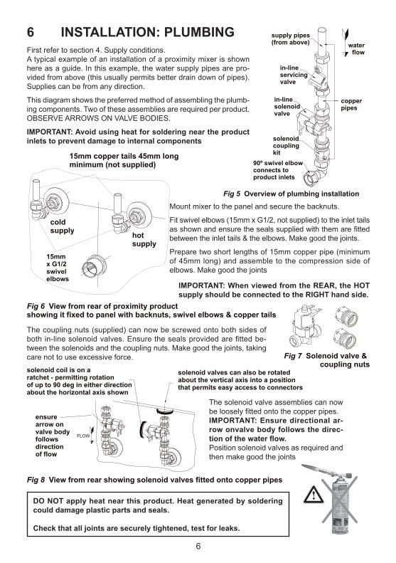
Fig 5 Overview of plumbing installation
Fig 6 View from rear of proximity product showing it fixed to panel with backnuts, swivel elbows & copper tails
Fig 7 Solenoid valve & coupling nuts
Fig 8 View from rear showing solenoid valves fitted onto copper pipes
ensurearrow onvalve bodyfollows directionof flow
coldsupply hot
supply
15mm copper tails 45mm longminimum (not supplied)
15mmx G1/2swivelelbows
solenoid coil is on a ratchet - permitting rotationof up to 90 deg in either directionabout the horizontal axis shown
solenoid valves can also be rotated about the vertical axis into a position that permits easy access to connectors
FLOW
First refer to section 4. Supply conditions.A typical example of an installation of a proximity mixer is shown here as a guide. In this example, the water supply pipes are pro-vided from above (this usually permits better drain down of pipes). Supplies can be from any direction.
This diagram shows the preferred method of assembling the plumb-ing components. Two of these assemblies are required per product.OBSERVE ARROWS ON VALVE BODIES.
IMPORTANT: Avoid using heat for soldering near the product inlets to prevent damage to internal components
Mount mixer to the panel and secure the backnuts.
Fit swivel elbows (15mm x G1/2, not supplied) to the inlet tails as shown and ensure the seals supplied with them are fitted between the inlet tails & the elbows. Make good the joints.
Prepare two short lengths of 15mm copper pipe (minimum of 45mm long) and assemble to the compression side of elbows. Make good the joints
IMPORTANT: When viewed from the REAR, the HOT supply should be connected to the RIGHT hand side.
The coupling nuts (supplied) can now be screwed onto both sides of both in-line solenoid valves. Ensure the seals provided are fitted be-tween the solenoids and the coupling nuts. Make good the joints, taking care not to use excessive force.
The solenoid valve assemblies can now be loosely fitted onto the copper pipes.IMPORTANT: Ensure directional ar-row onvalve body follows the direc-tion of the water flow.Position solenoid valves as required and then make good the joints
DO NOT apply heat near this product. Heat generated by soldering could damage plastic parts and seals.
Check that all joints are securely tightened, test for leaks.
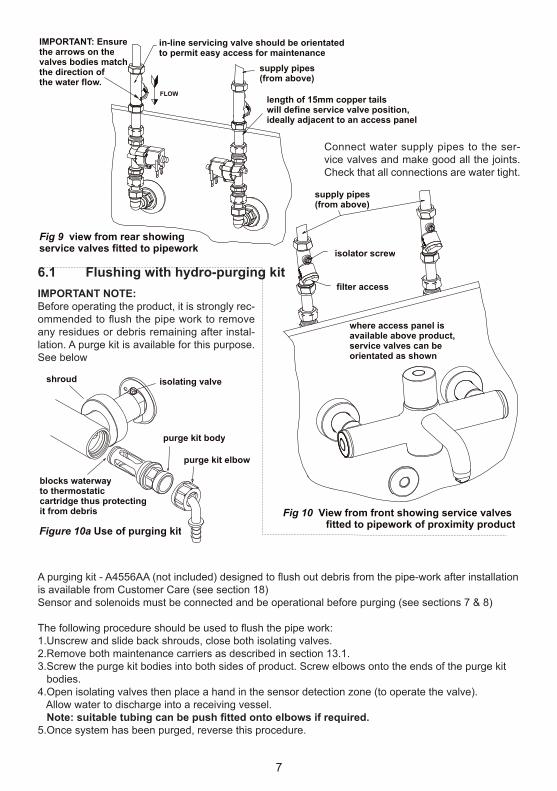
length of 15mm copper tailswill define service valve position,ideally adjacent to an access panel
IMPORTANT: Ensurethe arrows on thevalves bodies matchthe direction ofthe water flow.
Fig 9 view from rear showingservice valves fitted to pipework
Fig 10 View from front showing service valves fitted to pipework of proximity product
supply pipes(from above)
isolator screw
filter access
where access panel isavailable above product,service valves can beorientated as shown
Figure 10a Use of purging kit
shroud
purge kit body
purge kit elbow
isolating valve
supply pipes(from above)
in-line servicing valve should be orientatedto permit easy access for maintenance
FLOW
blocks waterwayto thermostaticcartridge thus protectingit from debris
Connect water supply pipes to the ser-vice valves and make good all the joints. Check that all connections are water tight.
IMPORTANT NOTE:Before operating the product, it is strongly rec-ommended to flush the pipe work to remove any residues or debris remaining after instal-lation. A purge kit is available for this purpose. See below
A purging kit - A4556AA (not included) designed to flush out debris from the pipe-work after installationis available from Customer Care (see section 18)Sensor and solenoids must be connected and be operational before purging (see sections 7 & 8)
The following procedure should be used to flush the pipe work:1.Unscrew and slide back shrouds, close both isolating valves.2.Remove both maintenance carriers as described in section 13.1.3.Screw the purge kit bodies into both sides of product. Screw elbows onto the ends of the purge kit bodies.4.Open isolating valves then place a hand in the sensor detection zone (to operate the valve). Allow water to discharge into a receiving vessel. Note: suitable tubing can be push fitted onto elbows if required.5.Once system has been purged, reverse this procedure.
7
6.1 Flushing with hydro-purging kit

7 INSTALLATION: ELECTRICAL
MAINS ELECTRICAL POWER SUPPLY
Mains powered Sensor Operated Products must be connected to a(fused / switched) continuous permanent power supply.
Connection to an interrupted power supply intended to stopelectrical consumption in an unused facility, may adversely affectthe Sensor product and is therefore not recommended.
Each time the power supply is reinstated the product entersreprogramming mode.
During reprogramming mode, any interaction (passive or active)with the product may alter the sensor settings in respect to rangeand / or run duration.
No significant savings will be achieved by connection to aninterrupted supply. These products are intrinsically economical interms of both water and electrical energy and will shut down in theevent of a sensor being obstructed.
8
Abbreviations & terminology used
PSU: Power Supply Unit, either mains, battery or link versions.
PCB: Printed Circuit Board inside the PSU.
RCD: Residual Current Device
SELV: Safety Extra Low Voltage

9
Fig13 View from rear showing solenoid valves link cable fitted
note: additional spadeconnectors on oneend of solenoid linkcable
connect other end oflink cable to terminalsof other solenoid
connect one endof link cable toterminals of onesolenoid
+-
solenoidvalveterminalsobserve + -
Fig12 View from rear showing one of the solenoid valves
Fig14 View from rear showing sensor cable fitted to one solenoid valve
connect sensorcable ontoadditional spades
Fig11 Showing overview of electrical installation
< mains power supply in
cable from sensor(grey)
sensor
solenoid linking cable(red & black)
cable fromsensor(red & black)
solenoids
PSUcase
Connection of this product to mains power supply should be undertaken by a competent person and should conform to IEE Wiring Regulations.
A typical example of an installation of a prox-imity mixer is shown here as a guide.
Orientation & position of solenoids, and PSU (Power Supply Unit) case can differ from in-stallation to installation.
An overview of the electrical wiring is shown in Fig 11With the product securely mounted to the panel &
plumbed-in, electrical work can commence.
First connect the two solenoid valves together using the separate link cable provided. The link cable isblack & red with connectors fitted at both ends. Cable length is 500mm.
Connect the cable to the solenoid valve terminals as shown. Observe the + and – symbols marked onthe solenoid valves, connect the red cables to + & black to -.
Note: one end of this link cable is fitted with additional spade connectors as shown. These connectors are for attaching the red & black sensor cable.
Locate the end of the red & black cable which is attached to the rear of the sensor. Cable length is 750mm.
Connect this cable to the spade connectors shown on the link cable. Observe + and – Ensure red is connected to red & black to black.

10
use either connectorfor grey sensor cable
grommet forsensor cable
lid screws
lid
lid seal
PCB
terminal blockfor mainsconnection
transformer withthermal fusecomplies withEN60950
PSU case
output voltage 6V- complies withIEE wiring regulationssafety extra low voltage(SELV)
grommet forpower cable(bottom entry)
mains supply (210 - 250 volt)should be via an RCD(max trip 30mA)and fused spur(fused at 3 amp)power cable not supplied
Fig15 Power Supply Unit (PSU)
Next, open the PSU case by un-screwing 4x posi-drive screws; the lid & seal should separate from the PSU case. Slide out the PCB (Print-ed Circuit Board) from the case.
With the mains power switched off, prepare the mains power cable (not supplied). This should be flexible 3A rated 2 core cable. Carefully remove about 100mm of outer cable sheath-ing, strip the wire ends back by about 5mm.
Feed the cable through the grommet at the base of the case (cut small slot in grommet first).
Connect the appropriate mains wires to the L (Live) & N (Neutral) marked on the terminal block on the PCB.
Slide the PCB back into the case (note guide slots), allowing the mains wires to rest in-front of the transformer.
DO NOT leave wires on top of the transformer as this may prevent the lid from closing completely
Locate the end of the second cable (grey with black line) which is attached to the rear of the sensor (cable end has connector fitted, length is 750mm). The cable can be slid into the upper grommet (which is pre-slit) & fed through the lid.
Plug this cable into either one of the two connectors on the PCB. The lid can now be closed, ensure the grommet is pressed into the lid. Check that no cables are trapped under the lid, make sure the lid seal is in place, and then refit the 4 retaining screws.
A pair of self-adhesive Velcro-type pads are provided. Attach one to the side of the PSU case & the other to a suitable location on the rear of the mounting panel.
Note: ensure the selected location does not stretch/stress the cables. Consideration should also be given to keeping the PSU case within easy reach/access for maintenance staff. Fasten the PSU case to the mounting panel.
This completes the behind-panel installation work.
IMPORTANT: Leave the sensor protective sticker in place for at least 20 seconds after powering-on the product.See section 8 regarding sensor adjustment
IMPORTANT: Ensure terminal block screws are firmly tightened & clamp the wires securely. Note earth connection is not required to PCB

11
8 OPERATION & SENSOR ADJUSTMENTOperation
Proximity mixer
Timed flow mixerdetectionzone
detectionzone
Figure 16
Step 1a Detection Range Adjustment
sensor
required range (max 250 mm)
sensor
30 - 50 mm
Step 1b
Figure 17
Figure 18
NOTE: Ensure there is no obstruction in the detection range during 'Power -Up' as this may cause the range to be changed.
Before programming remove sticky label over sensor face.
Both mixers are operated when the user places a hand in the detection zone.
With the proximity version, flow starts when a hand is placed in the detection zone andwill continue until it is removed.
The other version gives a timed flow which is started by placing a hand in the detection zone. Flow will then continue for a preset time of 60 seconds and then stop automatically. The preset time can be ad-justed by following the procedure outlined in the section on programming the sensor below.
After the initial 5 secs, the LED will stop flashing and will stay fully on for about 5 more secs.During this time, move hand to required range (up to a maximum of 250mm),Leave hand at this position for 5 seconds, the LED will start to flash again.If it is necessary to change the run time, go to Step 2 below, otherwise move hand away from detection range. The sensor now works normally and is no longer in programming mode. If an error is made in programming the detection range, it is necessary to start again from Step 1a.
PROGRAMMING THE SENSOR
Follow this procedure to change the Detection Range and the Run Time for timed flow productPLEASE NOTE: Only the detection range can be changed on proximity product. The run time is deter-mined by the presence of a hand in the detection zone, or the anti-vandal max run time.
The sensor can only be programmed just after power-up.Disconnect power supply from the mains, wait 30 seconds.Reconnect sensor to power supply - note LED in sensor flashes slowly for about 5 seconds.During this time, place hand 30 to 50 mm from sensor while LED flashes slowly.

12
PROGRAMMING THE SENSOR CONTINUED
9 COMMISSIONING AND AUDITS
sensor
30 - 50 mm
Step 2 Run Time Adjustment
Figure 19
No of LED Flashes 1 2 3 4 5 6 7 8 9Run Time (Seconds) 1 2 3.25 7.5 15 30 60 120 240
While the sensor LED is flashing, hold hand near to sensor (30 - 50mm),
The sensor LED turns off and starts to flash very slowly (once every 2 seconds),
Each flash will give a different time period, after 7 flashes take the hand away from the detection range. The run time is now set for 60 seconds.
For other run times, see the table below. The sensor now works normally, and is no longer in program-ming mode.If an error has been made in programming the run time, it is necessary to start from Step 1.
The following procedure should be conducted after installation to ensure the product isfunctioning correctly.
9.1 The Purpose of Commissioning:• To confirm the correct designation of product versus application.• To confirm the correct supply water conditions for the product / installation.• To adjust the mixed temperature if necessary to suit the water supply conditions of the installation.• To check the product is performing properly.• To start an audit log and record appropriate data.
This product is factory set at 40 ± 1°C * with supplies of circa; 3 bar balanced pressure andtemperatures of 15°C cold & 65°C hot (i.e. an inlet ∆t of 50°C & a hot / mix ∆t of 24°C )For supply requirements, see 4.0 Water supply conditions.
9.2 Commissioning Process• Establish that the supply conditions are within the requirements of HTM 04 and the supplyconditions outlined above. If not investigate.• When conditions are acceptable record them, together with hot and cold temperatures. Establish ∆t.
Check the outlet mix temperature is within 41°C ± 2°C *, if not (probably due to ∆t > 5 difference tofactory setting) adjust appropriately. (See 12.1)
• If mixed water temperature is correct undertake an ‘in field’ cold water isolation (CWI) test (See 9.5).Pass – restore supply and record mixed temperature,Fail – See 9.5 in field ‘Cold Water Isolation’ test.
9.3 Audit Checks on TMV’sThe purpose of a performance audit of a product is:• To check the product continues to perform properly.• To flag the need for the product to be adjusted due to supply condition changes or mechanismageing.• To ultimately identify the need for product maintenance.Note - Additionally these audits facilitate regular verification of the supply conditions in accordancewith HTM 04 requirements. (See decision tree FC3)
* See section 9.6: setting temperature

13
9.2 cont. Commissioning process (decision tree FC1)
NOTES:MWT - Maximum Working TemperatureCommissioning; Supply Conditions should be recorded
NOTE:Factory settings are:Inlet t = H - C = 65-15 = 50°CHot/Mix t = 65-41 = 24°C
∆∆
pass
accept
record mixed temperature
re-set mixed to 41 C +0/-2°C º
follow setting or maintenance
instructionsMWT 41 C (+0 / -º 2ºC) *
check the supply conditionspressure 0.2 - 5.0 bar & temperature <20ºC & >55º
record supply conditionsand ∆t for the hot & cold investigate
YES
YES
YES
NO
NO
NO
fail testundertake in-field cold waterisolation test - see see 9.5
Achieved 41 +0 / -2°C *
* See section 9.6: setting temperature

14
∆t>5ºC
is supply temperaturesame as previous audit?
YES
YES YES
YES
YES
YES
YES
NO
NO
NO
NO
NO
NO
record stable state supplytemperature (5 - 20 C)º
cold <20in 2 minutes
ºC supply pressuresare appropriate
hot>55in 1 minute
ºC
record stable state supplytemperature (55 - 65ºC)
is supply temperaturesame as previous audit?
insignificant changedifference <5 C∆t º
>65ºC
temporary changeof known cause
long term or permanentchange - consider
recommisioning of thermofitting(s)
implications to terminal fittings
investigate system issue
no action.retest when
conditions normaliseno action
go to D-08 field test audit 9.4or commissioning 9.2
follow commissioninginstructions see
9.4 Audit procedure (see decision tree FC2)
• Verify the water supplies conditions are similar to when the product was commissioned i.e. inlet ∆t as previous + / - 5C° Note: If inlet ∆t change is > 5C consider the cause of the change, If it is seen as a long term or permanent change, re-commission the product. If however, it is only a temporary change, retest when normal conditions resume.
• If inlet ∆t differs from the commissioning ∆t by < 5C° carry out field ‘cold water isolation’ (CWI) test as D-08: 2009. See 9.5 in field Cold Water Isolation test failure.• Pass - restore the cold supply and move on to check the mix temperature. Note: If the product fails CWI test, refer to 9.5 and then re-commission the valve.• Mixed Temperature is as commissioned ±2C°, Accept and record the temperature. Note: If mixed Deviation > ±2C° (1st instance) reset mix as instructions and redo the test from start. See 12.1 Adjustment of the mix temperature.• 2nd & subsequent instances follow maintenance instructions.
Audit of Supplies To Fittings (FC3)

15
Fitting Field Test Audit (FC2)
go to commissioning FC1 (9.2)
2nd instancefollow maintenance
instructions (section 12)
1st instancereset, follow
setting instructions
accept& record
mixed temp.
same as atcommissioning
2.0 C± ºdeviation from
previous >+2.0ºC
check mixedtemperature
restore cold
pass failsee 12
undertake the coldwater isolation test
see 9.5
water supplies same asprevious audit or
∆t change >5ºC
9.5 In-field ‘Cold Water Isolation’(CWI) test.Note: To gain access to the cold water isolat-ing valve, unscrew the right hand shroud (42) & slide forward to expose the isolating screw on top of the cold inlet leg (see fig 24, section 13). Using a flat-blade screw driver, the screw can be rotated 90° anti-clockwise to isolate the cold water supply.
Prior to commencing the CWI test, ensure:1. The water supply conditions are met either:A. For commissioning a new product (see table 1, section 4).B. Or the inlet ∆t is within ±5°C to when the product was commissioned (see 9.4). NOTE It is important that the hot temperature is greater than 55°C2. Mixed water outlet temperature is correct (see table 2, section 10).
To perform a CWI test, operate the productusing the sensor. Then conduct the following procedure:1. Record the steady state temperature of both hot and cold water supplies. Note the ∆t.2. Record the temperature of the mixed water at the outlet.3. Isolate the cold water supply (by rotating the isolating screw 90°) & monitor the flow of water from the outlet.
If the flow ceases, CWI test passed:1. Restore the cold water supply by rotating the isolator screw 90° clockwise.2. Slide the shroud back & screw onto the wall plate.3. Re-check the temperature of the stabilised mixed water at the outlet to ensure it is still correct. Accept & record mixed temperature.If there is an ongoing flow of water from the mixed water outlet, then 5 seconds after CWI collect the
discharging water into a measuring vessel for 60 seconds. To pass the CWI test the volume of collected water should be less than 120ml.
If the product fails CWI test, see FC2 (section 9). Follow product maintenance (see section 12) and servicing (see section 10) instructions.
9.6 Setting temperature for sensor operated mixers
These products do not allow the user to select the desired blend temperature. We therefore recommend setting a blend temperature of 39 to 40°C rather than the normally applicable 41°C maximum associated with “user adjustable” products. This ensures comfort to more sensitive users.

16
11 ARMITAGE BIOGUARD OUTLET
10 SERVICING - TVM3 SCHEME
10.1 FREQUENCY OF REGULAR SERVICING
The need for servicing is normally identified as a result of the regular performance auditing.
Table 2 A guide to maximum temperature sets
Permitted maximum stabilisedtemperature recorded during sitetesting – excluding transient spikes
Maximum mixed watertemperature duringnormal operation
Application
41ºC * 43ºCWashbasin
The purpose of servicing regularly is to monitor any changes in performance due to changes in either the system or the product. This may highlight the need to adjust either the supply system or the product. These products should be audited 6 to 8 weeks and again 12 to 15 weeks after commissioning. The results are to be compared against original commissioning settings. If there are no significant changes at the mixed temperature outlet then a 6 monthly servicing cycle may be adopted. Otherwise, servicing checks should be carried out more frequently (e.g. every 4 months).
Follow the recommended auditing and maintenance procedures detailed in sections 9 & 12. During servicing, note the following:1. Repeat the procedure of recording and checking supply temperatures. (The same type of measuring equipment should be used)2. If the temperature has changed significantly from the previously recorded valves, the following should be checked: a. All in-line or integral valve filters are clear of obstruction. b. All in-line or integral check valves are clean and working properly to prevent backflow. c. Any isolating valves are fully open. d. The thermostat is free of debris3. When satisfied with the mixed outlet temperatures re-record the temperatures.
11.1 Outlet cleaning
Traditional “flow straightener” type outlets have recently been identified by extensive research as an area most likely to harbour bacteria. This product uses an Armitage Bioguard outlet which replaces this traditional flow straightener with a fully open copper-lined waterway. This greatly reduces the risk of bacteria build-up whilst the copper lining has natural anti-microbial properties.Outlet is suitable for autoclaving (remove o-ring if exceeding 80°C).In the interests of infection control and health hygiene, the Armitage Bioguard Outlet is a supplement to, not a substitute for, standard infection control practices. Continue to follow all current protocols, includ-ing those practices related to cleaning and disinfection of surfaces. Refer to HTM04-01 for more details.Patent pending for Armitage Bioguard antibacterial outlet, application No: 10 2012 107 243.4
On a regular basis the outlet should be inspected and cleaned.To unscrew and remove the outlet, use an adjustable spanner on the flats (20mm). To refit, hand tighten and then use the spanner until the outlet has bottomed in the bore. Take care not to over tighten.In areas where lime scale build-up is prevalent this should be avoided by regular cleaning. If it should build up, it will have to be removed. An inhibited proprietary scale solvent can be used such a kettle des-caling solvent but it is important to follow the manufacturer’s guidelines. After descaling it is important to rinse the parts thoroughly in clean water. Clean carefully and do not use abrasive materials or scrapersNote: Lime scale deposits should be removed prior to using any disinfection treatments.
OUTLET FILTER: The Armitage Bioguard outlet can be removed (as described below) & re-placed with a universal filter adaptor, see section 18. The adaptor will accept most filter types which are externally threaded M24x1.
* See section 9.6: setting temperature

17
In response to the new requirements of HTM 04-01 Addendum, the designs of these mixers have been enhanced to permit easy demounting of the mixer from the inlets.
This updated design permits quick & easy removal of the mixer for cleaning, disinfection & maintenance purposes.
Prior to commencing this procedure, you should have available either a replacement mixer (without inlets) or a pair of protective cover caps. See section 18.
Disinfection by full immersion in an appropriate bactericidal solution is recommended for this assembly. Prior to immersion, the fitting should be clean and dismantled to a level that prevents air locking. In some cases it may be considered appropriate to dismantle the fitting prior to demounting.
The level of dismantling should be established as a result of practice and will be largely dependant upon the water quality and service life. As a minimum we recommend removal of the lever handle, thermo-static cartridge & the maintenance carriers in each side of the body. Cleaning the filter screens on the latter is of great importance, see section 13. All components can be immersed together unassembled.
Disinfected mixers should be promptly replaced or stored using an appropriate method until required. For disinfection solution see section 11.8
Method for demounting mixers:
1. Isolate the hot and cold water supplies using the integral ball valves. See section 13. Operate mixer lever to confirm water supplies are closed off.
2. Undo the 2 grub screws securing the mixer using a 3mm hexagon key. (Take care not to lose the screws).
3. Remove the mixer from the inlets, by gently pulling away as shown. Expect some trapped water to escape.
4. During cleaning protocols: Fit a replacement mixer (without inlets) to ensure continuity of use. Alternatively fit cover caps to protect & seal the inlets.
5. To refit the mixer; reverse this procedure. Tighten screws securely.
6. Follow the commissioning procedure to ensure the product is functioning correctly. See section 9.
11.7 Demounting mixer
Take care to avoid damaging the inlet seals. Damage to these seals would compromise the insulate feature & affect the mixer’s thermostatic performance. See section 15 for spare “demountable seal kit”.
3

18
If a replacement mixer is not available, a pair of protective cover caps should be fitted to the inlets. For product code see section 18.
For both practical and functional reasons along with environmental contamination reasons, the inlets should not be left open.
Push the caps onto the inlets until they stop against the shoulder.Take care not to damage the o-ring seals.Secure the caps with grub screws as shown using a 3mm hexagonal key. Leave the hot & cold supplies isolated.Cover caps should be disinfected / sterilised when necessary.
As discussed in section 11.7, for disinfection, we recommend parts be immersed in an appropriate bactericidal solution.
The frequency of such disinfection actions will be derived from regular sampling carried out under the regime of the Responsible Person (Water). We would not expect to need greater than 6 monthly fre-quencies, hopefully considerably less.
The need for excessive use of this procedure would be indicative of the need for some root cause analy-sis as there could be some system or behavioural problems that need addressing.
11.8 Disinfection solution
IMPORTANT: Do not leave the mixer inlets open without a body or cover caps fitted.
3
Protective cover caps
IMPORTANT ADMINISTRATION NOTE:Where an audit log document (report or electronic record) is being kept for a mixer, consideration should be given to the mixer’s traceability during the demounting & disinfecting process.
19
12 MAINTENANCE
12.1 Adjustment of the mix temperature:
12.2 Removal and inspection of cartridge
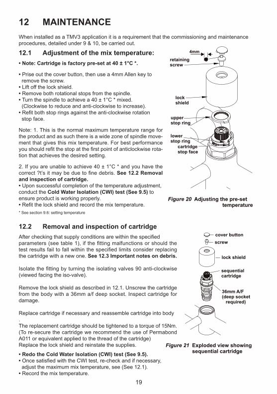
When installed as a TMV3 application it is a requirement that the commissioning and maintenanceprocedures, detailed under 9 & 10, be carried out.
4mm
retainingscrew
upperstop ring
lockshield
lowerstop ring
cartridgestop face
Figure 20 Adjusting the pre-set temperature
Figure 21 Exploded view showing sequential cartridge
cover buttonscrew
sequentialcartridge
lock shield
36mm A/F(deep socket required)
• Note: Cartridge is factory pre-set at 40 ± 1°C *.
• Prise out the cover button, then use a 4mm Allen key to remove the screw.• Lift off the lock shield.• Remove both rotational stops from the spindle.• Turn the spindle to achieve a 40 ± 1°C * mixed. (Clockwise to reduce and anti-clockwise to increase).• Refit both stop rings against the anti-clockwise rotation stop face.
Note: 1. This is the normal maximum temperature range for the product and as such there is a wide zone of spindle move-ment that gives this mix temperature. For best performance you should refit the stop at the first point of anticlockwise rota-tion that achieves the desired setting.
2. If you are unable to achieve 40 ± 1°C * and you have the correct ?t’s it may be due to fine debris. See 12.2 Removal and inspection of cartridge.• Upon successful completion of the temperature adjustment,conduct the Cold Water Isolation (CWI) test (See 9.5) toensure product is working properly.• Refit the lock shield and record the mix temperature.
After checking that supply conditions are within the specifiedparameters (see table 1), if the fitting malfunctions or should the test results fail to fall within the specified limits consider replacing the cartridge with a new one. See 12.3 Important notes on debris.
Isolate the fitting by turning the isolating valves 90 anti-clockwise (viewed facing the iso-valve).
Remove the lock shield as described in 12.1. Unscrew the cartridge from the body with a 36mm a/f deep socket. Inspect cartridge for damage.
Replace cartridge if necessary and reassemble cartridge into body.The replacement cartridge should be tightened to a torque of 15Nm. (To re-secure the cartridge we recommend the use of Permabond A011 or equivalent applied to the thread of the cartridge)Replace the lock shield and reinstate the supplies.
• Redo the Cold Water Isolation (CWI) test (See 9.5).• Once satisfied with the CWI test, re-check and if necessary, adjust the maximum mix temperature, see (See 12.1).• Record the mix temperature.
* See section 9.6: setting temperature
20
12.3 Important notes on debrisAlthough this product is protected by built-in filters, debris can still find its way to the thermostat housing area. This can happen during servicing for example. Remove cartridge (see section 12.2) and carry out an inspection.
12.4 Thermostatic Cartridge Ageing
12.5 Hygiene Flush (automatic)
Following many years of normal service you may notice the following: 1. The need to carry out more frequent adjustment of mixed temperature. 2. The thermostatic element may not pass the CWI test.
These issues could be due to the ageing of the thermostat which loses some expansion capability over time.
These are the principle objectives of testing, as they serve to indicate to maintenance staff the declining performance capability of the thermostatic cartridge.
For this reason the audit testing flow chart highlights that 2nd Instance CWI test failure or 2nd instance mixed deviation even with stable ‘as commissioned’ supply conditions and correct inlet supply ∆t’s, is potentially the first indication of the need to replace the cartridge.
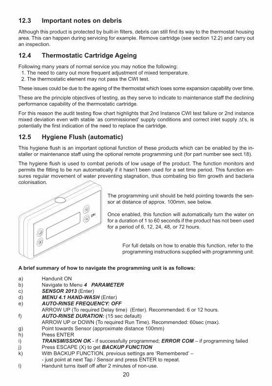
This hygiene flush is an important optional function of these products which can be enabled by the in-staller or maintenance staff using the optional remote programming unit (for part number see sect.18).
The hygiene flush is used to combat periods of low usage of the product. The function monitors and permits the fitting to be run automatically if it hasn’t been used for a set time period. This function en-sures regular movement of water preventing stagnation, thus combating bio film growth and bacteria colonisation.
a) Handunit ONb) Navigate to Menu 4 PARAMETERc) SENSOR 2013 (Enter)d) MENU 4.1 HAND-WASH (Enter)e) AUTO-RINSE FREQUENCY: OFF ARROW UP (To required Delay time) (Enter). Recommended: 6 or 12 hours.f) AUTO-RINSE DURATION: (15 sec default) ARROW UP or DOWN (To required Run Time). Recommended: 60sec (max).g) Point towards Sensor (approximate distance 100mm)h) Press ENTERi) TRANSMISSION OK - if successfully programmed; ERROR COM – if programming failedj) Press ESCAPE (X) to get BACKUP FUNCTION k) With BACKUP FUNCTION, previous settings are ‘Remembered’ – - just point at next Tap / Sensor and press ENTER to repeat.l) Handunit turns itself off after 2 minutes of non-use.
The programming unit should be held pointing towards the sen-sor at distance of approx. 100mm, see below.
Once enabled, this function will automatically turn the water on for a duration of 1 to 60 seconds if the product has not been used for a period of 6, 12, 24, 48, or 72 hours.
For full details on how to enable this function, refer to theprogramming instructions supplied with programming unit.
A brief summary of how to navigate the programming unit is as follows:

21
13 INTEGRAL VALVES
The integral isolation valves facilitate a number of activities:• Cleaning strainers• Servicing the thermostatic cartridge• Connecting hose for integral thermal disinfection• Audit cold water isolation test• Demounting the mixer from its inlets• Control flow during hydro-purge
Check valvesTo prevent back siphonage of water to the supply pipes, check valves are fitted inside the inlet tails (19) – see figure 27. These check valves can be maintained/replaced, but MUST NOT BE REMOVED.
Strainers
*To achieve a suitable flow rate where supply pressures are very low it may be necessary to remove theflow regulator (item 10 figure 27).
Figure 25 In-line isolating valve with filter
filtercap
10
2
1
isolating valves turn anti-clockwise to close whenfacing (the screw driverslot indicates the direction of flow)
shroud
cover cap
Strainer element (filter screen or mesh).End cap can be removed for cleaning.Recommend cleaning prior to disinfection.
flow regulator*
maintenance carrier & end cap
Figure 24 Exploded view showing strainers and flow regulator
13.2 MAINTENANCE OF IN-LINE COMPONENTSIn this example, (see figure 25) the isolator screw slot is shown in the vertical position. This indicates the valve is open. To close this valve, rotate the isolator screw by 90° into the hor-izontal position. By operating the product, this will drain down the water from the pipes below the service valve. Once the product has been isolated, this will permit maintenance staff to:
1. Check & clean the filters by unscrewing the filter cap.2. Replace the in-line solenoid valves if necessary.3. Completely remove the product from the panel if necessary.
13.1 ISOLATING VALVES
NOTE: The flow regulator fitted in each maintenance carrier is nominally rated 5L/min. Therefore mixer is flow regulated to max 10L/min
To ensure trouble free opera-tion of the fitting, the strainer elements should be checked and cleaned in accordance with the commissioning and servicing guide (see section 9 & 10).To access the strainer ele-ment, first unscrew and slide back the shrouds and close the isolation valves. Prise out the cover cap then un-screw the end cap using a 10 mm Allen key and withdraw the maintenance carrier. The strainer element should be washed with clean water and refitted.
IMPORTANT NOTE:The integral isolating valve(s) shown below should be used regularly for all servicing & testing of this product. This is in preference to using any external inline isolating valves which may have been fitted upstream of the inlet legs. Regular exercising of both isolating valves is essential.

22
14 INTEGRAL THERMAL-DISINFECTIONThis fitting is equipped with a disinfecting feature, which allows an engineer to feed water from the hot inlet via a temporary by-pass hose* into the cold inlet. This hot water then passes through the cold inlet, the thermostatic mixing chamber and out through the mixed water outlet. The temporary bypass hose is inserted into special valve connectors in the inlet tails normally concealed by the shrouds.
Safety Note: Care should be taken when carrying out the following procedure to avoidcontact with hot water and hot surfaces. We recommend the use of protective hand wear.
To disinfect the fitting proceed as follows:1. Unscrew the wall shrouds (42) and slide forward2. Isolate both inlets by turning the isolation valves through 90 anti-clockwise.3. Remove dust covers from the exposed nipples and push-fit the temporary flexible hose inserting the cold side first and then the hot.4. Now turn hot side isolating valve 90 deg clockwise.
When the fitting is operated hot water will now be able to pass from the hot inlet, through the by-pass hose into the cold inlet and thence into the thermostatic mixing chamber and spout. Here, by the nature of the thermostatic element, it will fully open the cold port. The hot water will then discharge to waste via the fitting’s spout, with a noticeable increase in surface temperature of the product.
5. Operate the fitting using the proximity sensor. (As flow will stop after 60 secs it will be necessary tostart the flow using the sensor a number of times to produce flow time indicated in Table 3.)
Following the recommended disinfection period, turn the hot isolation valve back to the isolation posi-tion, turn off the fitting and remove the bypass hose - hot side first then the cold. Turn both isolation valves back to the normal flow position. Check for normal operation of the fitting and replace dust caps and shrouds.
Temperature Disinfection time
60ºC
65ºC
70ºC
20 minutes
10 minutes
5 minutes
Table 3 Guide to disinfection temperatures v/s time
*The temporary bypass hose is available as an optional extra Part No. S8239NU)
S8239NU*
1
2
2
3
3
Dust Cover
90º
90º
4
5
Figure 26 Fitting the Temporary bypass hose
NOTE: Thermal disinfection will only have occurred if water has been discharged from the spout according to the table 3 above.

23
15 SPARE PARTS
1145
1716
15
18
19
20
22
26
25
1310 11
14
41
42
24
11a12
9
7
11a12
10
1413
11
5
1
2
3
34 or 35
34a
9
4144
22
Figure 27
For more information on spare parts why not visit our spare website:www.fastpart-spares.co.ukor contact customer care
fast t r a p

24
For more information on spare parts why not visit our spare website:www.fastpart-spares.co.ukor contact customer care
fast t r a p
16 SPARE PARTS LIST - MIxER
Ref. Description Part No.1 Lock shield -2 Cover cap E960615AA3 Handle screw A961950NU5 Sequential, thermostatic cartridge A962280NU5a Sequential, thermostatic cartridge (10 bulk pack) F960879NU7 Armitage Bioguard outlet with o-ring seal F960847AA9 Grub screw M6 x 6 - (available within item 44) -10 Flow regulator 5L/min (Pair) A962689NU11 O-ring dia 17.6 x 2.4 A962497NU11a O-ring 25.0 x 1.5 A962496NU12 O-ring dia 34.0 x 2.0 A960183NU13 End cap, maintenance carrier & filter (complete with o-rings) A962343AA14 Index button E960641AA15 Backnut E960112NU16 Slip washer dia 60 x 25 x 2 E960631NU17 O-ring 51.6 x 2.4 E960632NU18 Wall plate E960633NU19 Check valve DW15 (Pair) A962594NU20 Straight inlet tail with maintenance / disinfecting valve A962344AA22 O-ring dia 17 x 2.5 (set of 4) A963143NU24 O-ring dia 34.1 x 1.6 -25 Thermal disinfection nipple assembly (fit hand tight only) A962498AA26 Dust cover -34 Momentary action proximity sensor & housing E960619AA34a Sensor IR complete with wire A960219NU35 Timed flow proximity sensor & housing E960620AA41 O-ring dia 8.1 x 1.6 (single) - (available within item 44) A962345NU42 Shroud A962346AA44 Demountable seal kit with grub screws, o-rings & hex hey F961004NU45 Strainer & O-ring kit (10 bulk pack) F961078NU

25
Figure 28 Behind Panel Spares
Ref. Description Part No.
1 SV link cable 500 long (red & black) A962477NU2 Inline service valve with filter only. E960086NU3 SV coupler kit (pair) A962499NU4 Solenoid valve with seals A962478NU5 PCB only with transformer A960159NU6 Velcro pad kit A860704NU7 PSU Complete A962881NU
2
3
4
1
57
6
17 SPARE PARTS - ELECTRICAL

26
18 MARKWIK 21 ACCESSORIES
A6255AA Cover caps kit.To protect & seal the inlets legs whena mixer has been demounted & removed.See section 11.7
A6256AA Universal filter adaptor.Replaces the Armitage Bioguard outletto permit attachment of an outlet filter.Threaded M24x1 (internal).
A4556AA Hydro-purging kit.To assist with flushing pipework after installation. Suppliedin pairs with seals & swivel elbows.See section 6.1.
S8239NU Thermal disinfection kit.Flexible hose used with mixer’sintegral thermal disinfection feature.See section 14.
F960970NU Remote programming unit. See section 12.5
For more information on accessories contact our customer care.

27
19 CLEANING CHROME SURFACES
When cleaning chromed products use only a mild detergent, rinse & wipe dry with a soft cloth. Ideally clean after each use to maintain appearance.
Never use abrasive, scouring powders or scrapers. Never use cleaning agents containing alcohol, ammonia, hydrochloric acid, sulphuric acid, nitric acid,phosphoric acid or organic solvents. Use of incorrect cleaning products / methods may result in chrome damage which is not covered by the manufacturer’s guarantee.

0515 / A 866 628 40Made in Germany
AFTER SALES NON RESIDENTIAL HELPLINE
0870 122 8822AFTER SALES NON RESIDENTIAL FAx
0870 122 [email protected]
Armitage Shanks pursues a policy of continuing improvement in design and performance of its products.This right is therefore reserved to vary specifica-tion without notice.Armitage Shanks is a division ofIdeal Standard (UK) Ltd
Ideal Standard International BVBACorporate Village - Gent Building
Da Vincilaan 21935 Zaventem
Belgium
www.idealstandardinternational.com
For more information about our products visit our websites: www.armitage-shanks.co.uk www.idealspec.co.uk www.fastpart-spares.co.uk