installation use and maintenance instructions ...docs.whirlpool.eu/_doc/ifu_manual.pdf ·...
TRANSCRIPT

1
MANUALE ISTRUZIONI D‟INSTALLAZIONE, USO E MANUTENZIONE
INSTALLATION USE AND MAINTENANCE INSTRUCTIONS
INSTALLATIONS-, GEBRAUCHS- UND WARTUNGSANLEITUNG
MANUEL D'INSTRUCTION D'INSTALLATION, D'UTILISATION ET D'ENTRETIEN
FORNI ELETTRICI A CONVEZIONE E MISTI A
CONVEZIONE E VAPORE DIRETTO
PER GASTRONOMIA E PER PASTICCERIA
ELECTRIC, CONVECTION AND COMBINED
CONVECTION AND DIRECT STEAM OVENS
FOR GASTRONOMY AND FOR PASTRY
ELEKTROÖFEN, KONVEKTION UND KOMBIBETRIEB MIT
KONVEKTION UND DIREKTDAMPF
FÜR DIE GASTRONOMIE UND FÜR KONDITOREI
FOURS ÉLECTRIQUES, À CONVECTION ET MIXTES
CONVECTION ET VAPEUR DIRECTE
POUR GASTRONOMIE ET POUR PÂTISSERIE / BOULANGERIE
05-2011.a

2
Il costruttore si riserva il diritto di apportare modifiche alle caratteristiche tecniche e funzionali dei prodotti presentati in questa pubblicazione senza dare alcun preavviso; inoltre, non risponde di possibili inesattezze, imputabili ad errori di stampa o di trascrizione, contenute nel presente libretto. All specifications of this handbook are not binding and the manufacturer could change them without notice; the manufacturer declines any liability for possible misprints. Der Hersteller behält sich vor, die technischen und betrieblichen Merkmale der Erzeugnisse, die in dieser Veröffentlichung vorgestellt werden, ohne Vorabhinweis zu verändern. Darüber hinaus haftet er nicht für Unstimmigkeiten, die auf Druck- oder Übertragungsfehler in diesem Heft zurückzuführen sind. Le fabricant se réserve le droit d'apporter des modifications aux caractéristiques techniques et fonctionnelles des produits présentés dans cette publication sans aucun préavis ; en outre, il n'est pas responsable de possibles erreurs, imputables à des erreurs d'impression ou de transcription, contenues dans le manuel présent.
INDICE GENERALE- GENERAL INDEX- SOMMAIRE- INHALT
ITALIANO 2 ENGLISH 10 DEUTSCH 18 FRENCH 27
ITALIANO
Indice
1. AVVERTENZE
1.1. AVVERTENZE GENERALI 3
1.2. AVVERTENZE TECNICHE GENERALI 3
1.3. AVVERTENZE D‟UTILIZZO GENERALI 3
2. CARATTERISTICHE TECNICHE GENERALI 4
2.1. DATI TECNICI 4
3. AVVERTENZE PER L‟INSTALLATORE 5
3.1. RICEVIMENTO 5
3.2. MOVIMENTAZIONE 5
3.3. COLLOCAZIONE 5
3.4. COLLEGAMENTI 5
3.4.1. RETE ELETTRICA 5
3.4.1.1. SIMBOLO EQUIPOTENZIALE 5
3.4.2. RETE IDRICA 5
3.4.3. SCARICHI 6
4. INDICAZIONI D‟UTILIZZO PER L‟UTENTE FINALE 6
5. PANNELLO DI CONTROLLO E LEGENDA 8
6.MANUTENZIONE ORDINARIA 9
7. SMALTIMENTO DELL‟IMBALLO 9
8. DISMISSIONE E ROTTAMAZIONE DELL‟APPARECCHIATURA 9
9. SCHEMI D‟INSTALLAZIONE FORNI 35
10. SCHEMI ELETTRICI 36

3
1. AVVERTENZE
1.1. AVVERTENZE GENERALI
Il presente manuale è stato realizzato per permettere una corretta installazione, messa a punto e manutenzione dell'apparecchiatura. E‟ di fondamentale importanza che le avvertenze contenute nel presente libretto siano lette attentamente in quanto forniscono importanti indicazioni circa la sicurezza d'installazione, d'uso e di manutenzione. Il presente manuale e lo schema elettrico devono essere conservati con cura e messi a disposizione dell'operatore (installatore, tecnico ed anche utilizzatore finale) per ogni ulteriore consultazione. L'apparecchio deve essere installato, collaudato e assistito da personale qualificato in possesso dei requisiti di legge. L'apparecchiatura è stata progettata e realizzata per la cottura di prodotti alimentari e per la rigenerazione di alimenti congelati o surgelati, dovrà pertanto essere destinata solo all'uso per il quale è stata espressamente concepita. Qualsiasi impiego diverso da quello specificato non comporta per il costruttore impegno o vincolo d'alcun genere. Viene declinata ogni responsabilità del produttore con decadimento della garanzia in caso di modifiche elettriche e/o meccaniche. Manomissioni in genere non espressamente autorizzate e che non rispettino quanto riportato nel presente manuale, fanno decadere la garanzia. Per l'eventuale riparazione rivolgersi esclusivamente ad un centro di assistenza tecnica autorizzato dal costruttore e richiedere l'utilizzo di ricambi originali. In caso di dubbio non utilizzare l'apparecchiatura e rivolgersi a personale professionalmente qualificato. Il mancato rispetto di quanto sopra può compromettere la sicurezza dell'apparecchiatura. Osservare le norme di sicurezza locali vigenti al momento dell'installazione. Verificare che le caratteristiche della rete elettrica siano conformi ai dati riportati sulla targhetta matricolare. Il materiale di imballaggio (sacchetti in plastica, polistirolo espanso, chiodi, ecc.) in quanto potenziale fonte di pericolo deve essere tenuto fuori dalla portata dei bambini e correttamente riciclato secondo le norme locali in vigore.
1.2. AVVERTENZE TECNICHE GENERALI
- Ogni apparecchiatura è dotata di una targhetta caratteristiche, posta sul lato destro, in basso, che ne identifica il modello e i dati tecnici principali : LEGGERE I DATI RIPORTATI PRIMA DELL‟INSTALLAZIONE. - L‟apparecchiature deve essere installata in un locale aerato e ventilato. - L‟apparecchiatura deve essere adoperata solo da personale adeguatamente formato. - Tenere lontani i bambini dall‟apparecchiatura. - L‟utilizzo dell‟apparecchiatura richiede sorveglianza costante. Quando il forno è in funzione fare attenzione alle superfici esterne che si riscaldano: evitare di toccarle. - Chiedere all‟installatore l‟installazione di un addolcitore d‟acqua: in caso di mancanza l‟apparecchiatura potrebbe essere danneggiata gravemente dal calcare. - Si consiglia l‟installazione di un sifone in corrispondenza dell‟uscita dell‟acqua di scarico del forno (se il modello del forno è a vapore).
1.3. AVVERTENZE D‟UTILIZZO GENERALI
Al primo utilizzo: - In fase di primo utilizzo, fare attenzione che il libretto istruzioni, sacchetti di plastica e altri oggetti siano stati tolti dalla camera di cottura del forno. - Al primo utilizzo del forno si consiglia di farlo funzionare a vuoto per 30-40 minuti ad una temperatura di 200° C, così da eliminare odori sgradevoli di materiali usati per isolamenti termici o altri residui di lavorazione.
La pulizia:
- Prima di accendere il forno, per la prima volta, pulire accuratamente la camera di cottura utilizzando prodotti non corrosivi (alcalini) per non danneggiare le superfici. - Evitare di utilizzare materiali e prodotti abrasivi per non graffiare le superfici. - Alla fine dell‟utilizzo quotidiano pulire l‟interno della camera di cottura e l‟esterno dell‟apparecchiatura: questo prolungherà la durata dell‟apparecchiatura e ne assicurerà il buon funzionamento. - Non utilizzare getti d‟acqua in pressione per la pulizia del forno. - Evitare operazioni di salatura all‟interno della camera di cottura per non avere incrostazioni o depositi di sale. In caso di depositi risciacquare immediatamente ed asciugare con cura.
Precauzioni d‟uso:
- Per evitare bruciature, non utilizzare contenitori riempiti con liqudi o cibi che possono diventare fluidi con la cottura, nei livelli diversi da quelli che possono essere facilmente osservati.
- Dopo aver cucinato a vapore aprire con cautela la porta del forno, per evitare d‟entrare in contatto improvviso e diretto con il vapore ad alta temperatura, rimasto in camera di cottura. - Il non rispetto di questa precauzione potrebbe essere molto dannoso per l‟operatore. - E‟ vietato ostruire le prese d‟aria e tutte le altre aperture esistenti sul forno, in caso contrario si - comprometterà il funzionamento in sicurezza dell‟apparecchiatura.
Guasto e dismissione:
- Disattivare l'apparecchiatura in caso di guasto o di cattivo funzionamento. - In caso di dismissione dell‟apparecchiatura interrompere e scollegare le linee di alimentazione gas (ove presenti), energia elettrica ed acqua.

4
2. CARATTERISTICHE TECNICHE GENERALI
2.1. DATI TECNICI
620x630x500
500x380x300
3
3,2
0,31
40
620x630x650
500x380x450
3,35
3,55
0,40
48
780x680x500
3,35
3,55
230V 1N 50Hz
0,39
48
780x680x650
660x430x450
6
6,3
400V 3N 50Hz
0,50
62
230V 1N 50Hz 230V 1N 50Hz
kW
CONVEZIONE
CONVEZIONE+
VAPORE
DIMENSIONI ESTERNE
LxPxH (mm)
CAPACITÁ
PESOLORDO
(Kg)
VOLUME IMBALLO
(m³)
DIMENSIONI INTERNE
LxPxH (mm)
AFO 600 AFO 602 AFO 603
AFO 604 AFO 605 AFO 606 AFO 607
N° 3 GN 1/1 et 400X600
660x430x300
AFO 601
N° 5 GN 1/1 et 400X600
N° 3 2/3 GN 1/1 et
440x350 mm
N°5
440x350 mm
2/3 GN 1/1 et
FORNO+STAND+CAPPA
AxCxB(mm)
TOT.
kW
VOLTAGGIO
790x1000x1630 790x1000x1780 630x950x1630 630x950x1780
PROFONDITA‟ CON PORTA APERTA
AFO 600 1030 mm
AFO 601 1180 mm
AFO 602 980 mm
AFO 603 1130 mm
AFO 604 1030 mm
AFO 605 1180 mm
AFO 606 980 mm
AFO 607 1130 mm
B
A C

5
3. AVVERTENZE PER L‟INSTALLATORE
Leggere attentamente le istruzioni contenute in questo libretto , perché esse forniscono importanti indicazioni riguardo la sicurezza dell‟installazione, uso e manutenzione del forno. Conservare accuratamente questo manuale di modo da poterlo consultare in caso di problemi.Le operazioni d‟installazione e manutenzione dell‟apparecchiatura dovranno essere effettuate da un installatore autorizzato o da specialisti, conformemente alle norme di sicurezza in vigore. Il costruttore declina ogni responsabilita‟ in caso d‟inosservanza delle norme sopra citate. Il costruttore dichiara che le apparecchiature sono conformi alle norme CE. L‟installazione dovrà essere effettuata rispettando le norme in vigore, specialmente quelle riguardanti l‟aerazione dei locali ove sarà installata l‟apparecchiatura; installare il forno in un locale ben aerato.
3.1. RICEVIMENTO
L‟apparecchiatura arriva protetta da un imballo. Controllare all'arrivo che l'apparecchiatura non abbia subito danneggiamenti durante il trasporto e che la stessa sia completa nelle sue parti come da ordine. Nel caso di danni visibili annotare immediatamente sul documento relativo al trasporto il danno riscontrato riportando la dicitura : “RITIRO CON RISERVA PER EVIDENTI DANNI AD IMBALLO”. Importante: tutte le operazioni di seguito citate debbono essere eseguite in conformità' alle norme di sicurezza vigenti, sia per quanto relativo all'attrezzatura usata sia per quanto relativo alle modalità operative. Attenzione: prima di dar corso ad operazioni di movimentazione assicurarsi che la capacita' di sollevamento sia adeguata al peso dell'apparecchiatura in questione.
3.2. MOVIMENTAZIONE
L‟apparecchiatura può essere movimentata manualmente (almeno in 2 persone) tramite le maniglie poste sul cartone d‟imballo. ATTENZIONE: NEL CORSO DELLA MOVIMENTAZIONE NON CAPOVOLGERE O ROVESCIARE. AVVERTENZE: IL RISPETTO DELLE RACCOMANDAZIONI RIPORTATE SUL LATO ESTERNO DELL'IMBALLO È GARANZIA DI INTEGRITÀ FISICA E FUNZIONALE DELL'APPARECCHIATURA A TUTTO VANTAGGIO DELL'UTILIZZATORE FINALE. VIENE RACCOMANDATO QUINDI DI: - MOVIMENTARE CON CURA - TENERE ALL'ASCIUTTO - EVITARE NEL MODO PIÙ ASSOLUTO DI SOVRAPPORRE ALTRI OGGETTI ALL'APPARECCHIATURA. SOVRAPPORRE SOLAMENTE CON APPARECCHIATURE DELLO STESSO MODELLO E TIPO E NELLE QUANTITA‟ (N° PEZZI MASSIMI) RIPORTATE SULL‟IMBALLO.
3.3. COLLOCAZIONE
- togliere l‟imballo - togliere manualmente la pellicola di protezione sulle parti in acciaio, evitando di utilizzare sostanze abrasive e/o oggetti metallici - collocare l‟apparecchiatura assicurandosi che essa sia perfettamente in piano, altrimenti agire sui piedini ad altezza regolabile affinché essa sia posizionata in maniera corretta. Nel caso di forno+mobiletto neutro, alloggiare i piedini negli spazi appositamente creati sul mobiletto. - cercare di collocare l‟apparecchiatura distante almeno 50 cm dalla parete posteriore e da una delle 2 pareti laterali per consentire il collegamento del cavo di alimentazione elettrica, della rete idrica e del conduttore equipotenziale. - collocare l‟apparecchiatura in modo da rendere facilmente effettuabile qualsiasi operazione di installazione, manutenzione ordinaria e straordinaria, nonché interventi di riparazione. - mantenere comunque uno spazio minimo tra il forno e le apparecchiature ad esso vicine (dai 4 ai 6 cm) , questo per evitare riscaldamento di superfici attigue e per permettere un‟adeguata circolazione d‟aria.
3.4. COLLEGAMENTI
3.4.1. RETE ELETTRICA Il collegamento alla rete elettrica deve essere fatto rispettando le normative vigenti. Verificare che:
la tensione e la frequenza dell‟impianto di alimentazione corrispondano a quanto indicato sulla targhetta „‟dati tecnici‟‟ apposta sul lato destro dell‟apparecchiatura
l‟impianto possa supportare il carico dall‟apparecchio (vedere la targhetta con i dati tecnici)
l‟impianto sia munito di messa a terra secondo le norme in vigore
il sezionatore del forno sia raggiungibile facilmente anche dopo aver posizionato ed installato l‟apparecchiatura
la tensione di alimentazione, quando il forno è in funzione, non si discosti dal valore nominale di ± 10% I forni a gas monofase 230 V sono dotati di cavo con spina Schuko: inserire la spina nella presa elettrica dopo aver verificato che la presa sia adatta alla spina in dotazione. I forni trifase 400 V + Neutro, non sono dotati di cavo elettrico, quindi è necessario collegare alla morsettiera interna del forno un cavo tripolare più neutro più terra di adeguata sezione. La sostituzione del cavo deve essere eseguita da personale autorizzato e competente. Sostituzione del cavo: dopo aver aperto la copertura posteriore del forno (svitando le viti di fissaggio), collegare i conduttori secondo lo schema di collegamento scelto. Fissare il cavo con l‟apposito pressa cavo e poi chiudere il coperchio posteriore.
3.4.1.1. SIMBOLO EQUIPOTENZIALITA’
COLLEGAMENTO EQUIPOTENZIALE: necessario al collegamento di tutte le apparecchiature (elettriche e neutre) presenti nell‟installazione al fine di garantire un collegamento equipotenziale.
3.4.2. RETE IDRICA ( MODELLI MISTI CONVEZIONE+VAPORE) Tra la rete idrica e l‟apparecchiatura è preferibile mettere un rubinetto di intercettazione. L‟apparecchiatura è munita di un attacco maschio 3/4‟‟ e di filtro meccanico. Prima di installare il tubo di alimentazione si consiglia di fargli scorrere all‟interno acqua corrente in modo da pulire eventuali residui o polvere. Dati dell‟acqua: - La pressione consigliata per l‟acqua in ingresso deve essere inferiore a 200 kPa. Per pressioni maggiori è necessario installare un riduttore di pressione tarato a 200 kPa. - La temperatura massima dell‟acqua circa 30° C - la durezza massima 5°F (onde evitare incrostazioni calcaree, dannose per l‟apparecchiatura) - si consiglia l‟uso di un addolcitore per l‟acqua per evitare qualsiasi deposito di minerali nel forno.

6
3.4.3. SCARICHI Acqua Il tubo previsto, per l‟acqua di scarico, deve essere di un materiale in grado di sopportare la temperatura dell‟acqua in uscita dal forno (90° C) deve essere posizionato dietro il forno e collegato ad uno scarico sifonato per mezzo di un condotto rigido o flessibile. I tubo avrà diametro dimensionato al diametro foro di scarico e lunghezza pari ad un metro senza gomiti o strozzature e per facilitare il deflusso fare in modo che sia 20 cm al di sotto dell‟attacco scarico. Fumi Lo scarico dei fumi è nello schienale ed è convogliato da un tubo verso l‟alto: attenzione a non otturare i camini di scarico ed accertarsi che i camini non sfiatino in corrispondenza di materiali o arredi che ne potrebbero risultare danneggiati. Dopo aver verificato quanto sopra il forno può essere posizionato sotto una cappa aspirante (dotata di filtro) o sotto un soffitto aspirante
4. INDICAZIONI D‟UTILIZZO PER L‟UTENTE FINALE
INTERFACCIA UTENTE
SCHEDA NON ALIMENTATA In questo stato tutti i display e LED sono spenti. I relè sono nel loro stato normale senza alimentazione. ALIMENTAZIONE DELLA SCHEDA Appena alimentata la scheda esegue un lamp-test di tutti i LED e display per alcuni secondi, al termine del quale si porta nello stato di STAND-BY. Premendo il tasto PHASE (7) durante il lamp test vengono visualizzate prima la versione e poi la revisione del firmware della scheda. STATO STAND-BY In questo stato tutti i display e LED sono spenti; i relè non sono eccitati. Premendo l‟ENCODER (10) la scheda si porta in stato di STOP. STATO STOP In questo stato la scheda è pronta per l‟impostazione e l‟avvio di un ciclo di cottura. L‟interfaccia utente è stata pensata prevedendo 3 funzioni ad accesso diretto PHASE (7), UMIDITA‟ MANUALE (9, led 5) e START/STOP(8, led 6) e 4 funzioni con accesso da encoder TEMPERATURA (3), TEMPO(2), UMIDITA‟ (1) e PROGRAMMI(4). In assenza di allarmi e a ciclo impostato la pressione singola del tasto START/STOP (8) fa partire il ciclo di cottura e porta la scheda in stato di START. Tenendo premuto il tasto START/STOP (8) la scheda si porta in stato di STANDBY. In STOP il display visualizza normalmente la temperatura misurata nella camera, a meno che non si stia impostando o visualizzando un setpoint (tempo, camera, umidità); altre visualizzazioni possibili per il display verranno dettagliate nei paragrafi successivi. Ruotando o premendo l‟encoder inizia a lampeggiare il LED TEMPO (2) e continuando nella rotazione il LED lampeggiante scorre ciclicamente le 4 funzioni con accesso da encoder. Il display visualizza il set per le 3 funzioni temperatura, tempo e umidità e il codice dell‟eventuale programma attivo per la funzione programmi. Premendo l‟encoder si seleziona la funzione evidenziata dal LED lampeggiante; nei paragrafi seguenti i dettagli relativi a queste funzioni. Dopo un timeout di 5 sec di inattività si esce dalla modalità selezione funzione da encoder. Se presente un allarme ne viene data segnalazione visualizzando il codice relativo nel display e il buzzer suona. Alla prima pressione di un tasto il buzzer viene tacitato. Per ulteriori dettagli si faccia riferimento al capitolo DIAGNOSTICA. La scheda ritorna in stato STAND-BY dopo un timeout di inattività (10 minuti). GENERALITA‟ SUI CICLI DI COTTURA Ciascun ciclo di cottura (manuale o programma) può essere composto da un massimo di 3 fasi; ciascuna fase necessita di 3 valori di set: temperatura, tempo e umidità. Se è attivo un programma viene evidenziato dal LED PROGRAMMI (4). Il numero di LED PHASE (11: 1-2-3) accesi indica il numero di fasi del ciclo selezionato e il LED PHASE lampeggiante indica quale fase è attualmente visualizzata. Il LED UMIDITA‟ (1) acceso fisso indica che è impostato un set di umidità diverso da 0; in caso contrario il LED sarà spento. Ad ogni accensione (passaggio da STANDBY a STOP) il forno carica l‟ultimo ciclo manuale salvato. Alla prima accensione il ciclo manuale di default è definito da una fase con preset camera definito da parametro, tempo di cottura non impostato e umidità non attiva; tale ciclo non può essere avviato in quanto necessita l‟impostazione del tempo di cottura da parte dell‟utente. Al tentativo di avviare il ciclo il buzzer emette un suono di tonalità bassa (“boop”) ad indicare che l‟azione tentata non è consentita. IMPOSTAZIONE DELLA TEMPERATURA Ruotare l‟encoder fino a portare il LED lampeggiante sulla funzione TEMPERATURA (3). Il display indica il set attuale della temperatura non lampeggiante. Premendo l‟encoder (10) il display inizia a lampeggiare e il LED (3) rimane acceso fisso, a indicare che si sta modificando il set della temperatura. Ruotando l‟encoder (10) si modifica il valore del set di temperatura tra due limiti definiti da parametro e premendolo si conferma il valore selezionato. Ruotando l‟encoder (10) fino ad inizio scala si può selezionare una fase di pausa identificata dalla stringa “PAU” a display. Dopo un timeout di inattività di 5 sec si esce dalla modifica del set di temperatura tornando alla selezione funzione da encoder (lampeggia solo il LED) non confermando il valore selezionato. IMPOSTAZIONE DEL TEMPO Per l‟impostazione del tempo di cottura evidenziare la funzione TEMPO (2). Il display indica il set del tempo di cottura nel formato h.mm, impostabile tra 0.01 e 9.59; se il tempo di cottura impostato è infinto il display visualizza “Inf”, mentre se il tempo non è impostato (come nel caso del ciclo di default caricato all‟accensione o della creazione di una nuova fase) il display visualizza “---”. Premendo l‟encoder(10) il display inizia a lampeggiare e il LED rimane acceso fisso, a indicare che si sta modificando il set del tempo di cottura. Partendo dall‟inizio scala (rotazione completa antioraria) e ruotando poi in senso orario l‟encoder (10) si scorrono in ordine le seguenti impostazioni: “---”, “Inf” e poi i tempi da 0.01 a 9.59. Lo scorrimento è ciclico e cioè dopo 9.59 ritorna a “---”. Premendo l‟encoder (10) si conferma il valore selezionato; dopo un timeout di inattività di 5 sec si esce dalla modifica del set di temperatura tornando alla selezione funzione da encoder (10) (lampeggia solo il LED) non confermando il valore selezionato. IMPOSTAZIONE DELL‟UMIDITA‟ (PRESENTE SOLO SE IL FORNO E‟ A VAPORE) Evidenziare la funzione UMIDITA‟ (1) tramite l‟encoder (10) portando a lampeggiare il LED relativo; il display visualizzerà il set dell‟umidità. Premendo l‟encoder (10) il display inizia a lampeggiare e il LED rimane acceso fisso, a indicare che si sta modificando il set dell‟umidità. Ruotando l‟encoder (10) è possibile selezionare un valore tra 0 e 10 e confermarlo premendo l‟encoder (10). Dopo un timeout di inattività di 5 sec si esce dalla modifica del set di temperatura tornando alla selezione funzione da encoder (lampeggia solo il LED) non confermando il valore selezionato.

7
FASI DI COTTURA Ciascun ciclo di cottura, sia esso un programma o un ciclo manuale, può essere composto fino a un massimo di 3 fasi. Il numero di led PHASE accesi indica il numero di fasi del programma selezionato (comprese le fasi di pausa e quelle con tempo di cottura non impostato) e il led PHASE lampeggiante indica quale fase del ciclo è attualmente visualizzata. La fase selezionata può essere cambiata a rotazione premendo il tasto PHASE (7); se non si è in modalità selezione funzione da encoder alla pressione del tasto PHASE (7) viene mostrato per 3 sec il set del tempo (si accende anche il LED TEMPO 2), in modo da facilitare l‟individuazione di eventuali fasi con tempo non impostato. Ad ogni pressione prolungata del tasto PHASE (7) viene aggiunta una fase dopo la fase lampeggiante e la nuova fase aggiunta diventa quella attualmente selezionata e lampeggiante. Le fasi seguenti quella selezionata traslano di una posizione per far posto alla nuova fase. Non è possibile creare una fase dopo la terza. Se sono già presenti 3 fasi e ne viene creata una nuova, la terza viene eliminata. Le fasi aggiunte hanno preset camera definito da parametro, tempo di cottura non impostato e umidità non attiva. Le fasi di cottura che non hanno un tempo di cottura impostato non vengono eseguite in START e si passa alla fase successiva impostata; un ciclo di cottura per essere avviato deve avere almeno una fase con tempo impostato. Per cancellare la fase attuale, selezionare la funzione TEMPO (2) e ruotare l‟encoder (10) ad inizio scala in modo da visualizzare “---”; confermando tale valore la fase selezionata viene cancellata. Le fasi seguenti traslano indietro di una posizione in modo da occupare la posizione vacante; nel caso in cui si imposti a “---” il tempo di un ciclo costituito solo da una fase, essa non viene cancellata ma il ciclo non può essere avviato fino a che non viene impostata una fase valida. PROGRAMMI DI COTTURA Il forno può memorizzare le impostazioni di 20 programmi di cottura più un ciclo manuale. Da fabbrica il forno imposta tutti i programmi con il ciclo di default: 1 fase con preset camera definito da parametro, tempo di cottura non impostato e umidità non attiva. Ciascun programma può essere costituito al massimo da tre fasi e memorizza le impostazioni che normalmente si usano in un ciclo di cottura manuale: - set temperature - set tempo - set umidità Ciascun programma può essere modificato e avviato con tali modifiche. Esse tuttavia non vengono salvate in automatico ma richiedono un‟azione dell‟utente. Per salvare le nuove impostazioni è necessario tenere premuto l‟encoder (10) per 2 secondi (se non si sta modificando un set) e l‟avvenuto salvataggio verrà confermato dal buzzer. Per selezionare un programma ruotare l‟encoder (10) fino a far lampeggiare il LED PROGRAMMI (4) . Il display mostrerà il codice dell‟eventuale programma attivo nel formato P01 - P20 oppure “---” se attualmente si è in cottura manuale. Premendo l‟encoder (10) il display inizia a lampeggiare e il LED (4) rimane acceso fisso; ruotando l‟encoder (10) si può selezionare un programma tra P01 e P20; portandosi ad inizio scala (prima di P01) viene visualizzata la stringa “---” che indica l‟uscita dalla modalità programmi e la selezione del modo manuale. Premendo l‟encoder si seleziona il programma voluto, il display smette di lampeggiare mentre il LED (4) programmi ricomincia a lampeggiare, ad indicare che ruotando l‟encoder (10) si possono selezionare i set del programma. Per deselezionare il programma e tornare alla modalità manuale scegliere la stringa “---” all‟interno del menù programmi. Quando è selezionato un programma è possibile apportarvi delle modifiche agendo come nella modalità manuale. Le modifiche apportate non vengono salvate in automatico, ma è possibile far partire un ciclo di cottura con programma modificato. AVVIO DI UN CICLO La pressione del tasto START/STOP (8) avvia il ciclo di cottura (manuale o programma) attualmente selezionato e porta il forno in stato START; perché un ciclo possa essere avviato deve essere costituito almeno da una fase con set del tempo impostato. Il LED START/STOP (6) è acceso fisso e vengono attivate le regolazioni opportune. Non è possibile avviare un ciclo di cottura se si è in fase di impostazione di un set (temperatura, tempo, umidità) o dal menù di selezione di un programma. STATO START In stato di START la scheda avvia il ciclo di cottura selezionato e inizia le regolazioni opportune. Il LED START/STOP (6) è acceso fisso. Normalmente durante il ciclo il display mostra il tempo mancante alla fine della fase (con il puntino lampeggiante). Premendo l‟encoder (10) è possibile visualizzare per 5 sec la temperatura misurata in camera. Per modificare i set agire come in STOP: ruotare l‟encoder (10) fino a selezionare la funzione voluta (temperatura, tempo, umidità), premere l‟encoder (10), selezionare il valore voluto e confermarlo con la pressione dell‟encoder (10). E‟ presente un timeout di 5 sec il quale non conferma il valore selezionato. In ogni caso le modifiche non vengono memorizzate e vengono tenute buone solo per il ciclo in corso; a fine ciclo esse vengono eliminate. Non è possibile salvare le modifiche al programma quando si è in START. Le fasi con tempo non impostato non vengono eseguite. Il buzzer segnala il raggiungimento del set di temperatura della prima fase. Premendo il tasto UMIDITA‟ MANUALE (9) si accende il LED relativo (5) e viene aggiunto vapore in camera per circa 10 sec. Tenendo premuto il tasto START/STOP (8) la scheda termina la cottura e si porta in stato di STOP, dandone segnalazione con il buzzer. Premendo il tasto START/STOP (6) (pressione singola) o aprendo la porta la scheda si porta in stato di STOP TEMPORANEO. Tenendo premuto il tasto PHASE (7) viene terminata la fase in corso e si passa alla successiva. Il buzzer emette un beep prolungato; se era in corso l‟ultima fase la cottura viene terminata e il forno passa in STOP. La fase in esecuzione è segnalata dal led PHASE (7) lampeggiante. Non è possibile visualizzare, modificare, aggiungere o togliere fasi successive a quella in corso, né accedere al menù programmi (4) (è possibile però visualizzare il codice del programma in esecuzione). Alla fine del ciclo il buzzer suona e la scheda si porta in STOP (alla pressione di un tasto o all‟apertura della porta il buzzer viene tacitato). STATO STOP TEMPORANEO In stato di STOP TEMPORANEO vengono sospese le regolazioni e spenta la ventola. Il timer del ciclo a tempo viene sospeso e il puntino del display smette di lampeggiare. Il LED START/STOP è lampeggiante. Premendo nuovamente il tasto START/STOP (8) riprende il ciclo di cottura se la porta è chiusa. Chiudendo la porta riprende il ciclo di cottura se l‟interruzione è avvenuta in seguito a un‟apertura della porta (e non è stato premuto il tasto START/STOP). Premendo il tasto START/STOP prolungato la cottura termina e la scheda si porta in stato STOP. Le modifiche al ciclo in corso possono avvenire sotto le stesse condizioni che in START. MANCANZA DI ALIMENTAZIONE Se la tensione di alimentazione viene a mancare per un periodo di tempo sufficientemente lungo da spegnere la scheda, al successivo ritorno dell‟alimentazione il controllo esegue un lamp-test e si porta in stato di STOP, indipendentemente dallo stato in cui si trovava al momento dell‟interruzione.

8
5. PANNELLO DI CONTROLLO E LEGENDA
1
2
3
2 3 4 6
7 8
1
2
3
1 2 34 5 6
7 9
CONVEZIONE
CONVEZIONE E VAPORE DIRETTO
810
10
11
11
UMIDITÀ / HUMIDITY
AUMENTO MANUALE DELL‟UMIDITÀ / MANUAL INCREASE OF HUMIDITY
LUFTFEUCHTIGKEIT / HUMIDITÉ
MANUELLE LUFTFEUCHTIGKEITSTEIGERUNG / AUGMENTATION MANUEL DE L‟HUMIDITÉ
TEMPO DI COTTURA / COOKING TIME
START - STOP - PAUSA / START - STOP - PAUSE
KOCHZEIT / TEMPS DE CUISSON
START - STOP - PAUSE / START - STOP - PAUSE
TEMPERATURA DI COTTURA / COOKING TEMPERATURE
FASE DI COTTURA / COOKING PHASES
KOCHTEMPERATUR / TEMPÉRATURE DE CUISSON
KOCH PHASEN / PHASES DE CUISSON
MENÙ-SALVA / MENU-SAVE MENÜ-SPEICHERN / MENU-ENREGISTER
1
2
3
4
5
6
7
89
10
SELEZIONE-CONFERMA / SELECTION-CONFIRMAUSWAHL-BESTÄTIGUNG/ SELECTION-CONFIRMIR
11 FASE DI COTTURA / COOKING PHASESKOCH PHASEN / PHASES DE CUISSON
1
2
3

9
6. MANUTENZIONE ORDINARIA
Tutte le operazioni di manutenzione devono essere effettuate unicamente da personale qualificato. Prima di iniziare qualsiasi operazione di manutenzione è obbligatorio spegnere l‟apparecchiatura e scollegarla dalla rete elettrica e dalla rete idrica. PULIZIA DEL FORNO Pulire il forno alla fine del servizio giornaliero con prodotti adeguati: 1- usare acqua tiepida e saponi neutri o detergenti neutri 2- risciacquare accuratamente con acqua 3- asciugare con cura Non usare spatole o spazzole abrasive o altri utensili: questi potrebbero rovinare le superfici in acciaio e rilasciare depositi ferrosi che con l‟andare del tempo creerebbero ruggine. Non utilizzare getti d‟acqua per lavare il forno. Per pulire le parti in acciaio non utilizzare prodotti a base di cloro (candeggina, acido cloridrico) nemmeno se sono diluiti in acqua. Dopo ogni cottura specifica e prima della successiva, è consigliabile pulire eventuali resti di alimenti (grassi o sughi) nella camera di cottura del forno. Per la pulizia della camera di cottura del forno si raccomandano prodotti adatti e accuratezza nell‟operazione: tralasciare piccoli depositi di cibo o grasso negli angoli reconditi potrebbe a lungo andare danneggiare l‟apparecchiatura e creare fumi e odori indesiderati nella camera di cottura, nei casi più gravi ostruire prese d‟aria o danneggiare movimenti meccanici. In caso di inutilizzo dell‟apparecchiatura per lungo periodo si raccomanda di: 1- premere a lungo il tasto di STOP quando l‟apparecchiatura è in STATO DI STOP, per spegnerla 2- chiudere i rubinetti che la collegano alla rete elettrica, idrica e gas (ove presente) 3- lasciare leggermente aperta la porta dell‟apparecchiatura affinché ci sia un passaggio d‟aria e l‟apparecchiatura non abbia fenomeni di condensa o odori all‟interno della camera di cottura 4- con l‟aiuto di un panno stendere un velo protettivo d‟olio di vaselina su tutte le superfici in acciaio inox. SI RACCOMANDA DI SOTTOPORRE L‟APPARECCHIATURA PERIODICAMENTE (ALMENO UNA VOLTA L‟ANNO) AD UN CONTROLLO TOTALE DA PARTE DI UN TECNICO SPECIALIZZATO.
7. SMALTIMENTO DELL‟IMBALLO Smaltire i prodotti di imballo facendoli confluire ai centri di raccolta o di riciclaggio specializzati attenendosi alle norme vigenti.
8. DISMISSIONE E ROTTAMAZIONE DELL‟APPARECCHIATURA
Nel caso di dismissione, prima di rottamare l'apparecchiatura è doveroso renderla inoperante togliendo il cavo d'alimentazione, eliminando quelle parti che possono costituire un pericolo e rendendo inservibili serratura, cerniera od altri sistemi. IMPORTANTE: RISPETTARE LE NORMATIVE LOCALI PER LA ROTTAMAZIONE DI QUESTO GENERE DI APPARECCHIATURA

10
ENGLISH Index
1. WARNINGS 11
1.1. GENERAL WARNINGS 11
1.2. GENERAL TECHNICAL WARNINGS 11
1.3. GENERAL USE WARNINGS 11
2. GENERAL TECHNICAL FEATURES 12
2.1. DATA SHEET 12
3. WARNINGS FOR THE INSTALLER 13
3.1. CONTROLS AT RECEPTION 13
3.2. HANDLING 13
3.3. PLACING 13
3.4. CONNECTIONS 13
3.4.1. ELECTRICAL CONNECTIONS 13
3.4.1.1. EQUIPOTENTIAL SYMBOL 13
3.4.2. WATER CONNECTIONS 13
3.4.3. DRAINING WATER 13
4. INDICATIONS FOR THE FINAL USER 14
5. CONTROL PANEL AND LEGEND 16
6. ORDINARY MAINTENANCE 17
7. UNPACKING AND DISPOSE OF IT 17
8.DISPOSAL OF UNIT 17
9. INSTALLATION SCHEME 35
10. WIRING DIAGRAM 36

11
1. WARNINGS
1.1. GENERAL WARNINGS
This manual has been prepared to enable a correct installation, regulation and maintenance of the appliance. It is therefore of basic importance that the warnings contained in this booklet are carefully read as they supply essential indications regarding the safety of the installation, use and maintenance. This manual and the wiring diagram must be stored with care and made available to the operator (technical qualified personnel, final user) for any future consultation. The appliance must be installed, tested and serviced by legally qualified personnel. The appliance has been designed and constructed for the cooking of foodstuffs and should therefore be destined to this sole purpose for which it has been expressly conceived. Any use besides this specific purpose does not commit the constructor in any way. The constructor declines all responsibility with invalidity of the warranty in the event of electrical and/or mechanical modifications. Any adjustment whatsoever not expressly authorised and in disrespect of this manual will cause the invalidation of the warranty. For eventual repairs contact exclusively the authorised service centre and request the use of original spare parts. If in doubt do not use the appliance and contact professionally qualified personnel. The disrespect of the above conditions could risk the safety of the appliance. Observe all existing local regulations at the time of installation. Check that the characteristics of the electric grid correspond to the data given on the serial plate of the appliance. The packing materials (plastic bags, polystyrene, nylon, etc.) as potential hazards, must be kept out of the reach of children and properly recycled according to the existing local regulations.
1.2. TECHNICAL GENERAL WARNINGS
Every appliance has a technical data plate on the right side, reporting the model and the main characteristics: READ CAREFULLY THE TECHNICAL DATA BEFORE INSTALLING THE APPLIANCE!!!
Place the oven in a ventilated room.
The appliance is intended for professional use and must be used only by qualified personnel only.
Keep off the children from the appliance above all if it is in function.
The appliance should be constantly overseen while operating.
There are surfaces of the oven that become hot during operation. Take care of this.
Ask the installer for information on correct operation and use of the water softener; incorrect or incomplete maintenance is at the origin of the formation of scale, which would badly damage the oven.
It‟s suggested to install a siphon placed at the exit of drain water, if the model is with steam injection.
Every appliance has a serial plate on the right side.
1.3. GENERAL USE WARNINGS
Starting to use the oven: at the first use .
Pay attention to remove from the cooking chamber all stranger material like manual, plastic bags, polystyrene, nylon, etc, before starting to operate with the oven
Leave the cooking chamber empty and heat up the oven about 30-40 minutes long at the temperature of 200°C to eliminate any thermic insulation smell.
Cleaning
Clean the inside and outside surfaces only with warm water and soap or a neutral detergent. Rinse with plenty of water and dry thoroughly.
Don‟t use abrasive brushes or other damaging materials for the appliance‟s surfaces.
At the end of the working day, clean the inside (above all) and outside of the oven , to ensure smooth operation of the appliance and to prolong its useful life.
Do not use high pressure water jets when cleaning the appliance.
Avoid any operation that might cause cooking salt to be deposited on the steel surfaces of the oven; if salt is accidentally spilled, rinse off immediately and thoroughly.
Using precautions
Open the door of the oven slowly, to avoid to get burned by the hot steam.
Never obstruct any air inlet on the oven, in order to not compromise its performance and safety, when the appliance is operating
Never stretch the power cable.
Breakdown and final disposing
Shutdown the appliance in the event of breakdown or malfunctions.
disconnect it from electrical, gas (if you have a gas oven) and water system.
For the final disposal of this appliance, comply with local regulations in force.

12
2. GENERAL TECHNICAL FEATURES
2.1. DATA SHEET
DEPTH WITH OPEN DOOR
AFO 600 1030 mm
AFO 601 1180 mm
AFO 602 980 mm
AFO 603 1130 mm
AFO 604 1030 mm
AFO 605 1180 mm
AFO 606 980 mm
AFO 607 1130 mm
B
A C
620x630x500
500x380x300
3
3,2
0,31
40
620x630x650
500x380x450
3,35
3,55
0,40
48
780x680x500
3,35
3,55
0,39
48
780x680x650
660x430x450
6
6,3
0,50
62
kW
TOT.
kW
CONVECTION
CONVECTION+
STEAM
DIMENSIONS
WxDxH (mm)
EXTERNAL
CAPACITY
GROSSWEIGHT
(Kg)
PACKED VOLUME
(m³)
INTERNAL
DIMENSIONSWxDxH (mm)
AFO 600 AFO 602 AFO 603
AFO 604 AFO 605 AFO 606 AFO 607
N° 3 GN 1/1 et 400X600
660x430x300
AFO 601
N° 5 GN 1/1 et 400X600
N° 3 2/3 GN 1/1 et
440x350 mm
N°5
440x350 mm
2/3 GN 1/1 et
OVEN+STAND+HOOD
AxCxB(mm)
230V 1N 50Hz 400V 3N 50Hz 230V 1N 50Hz 230V 1N 50HzVOLTAGE
790x1000x1630 790x1000x1780 630x950x1630 630x950x1780

13
3. WARNINGS FOR THE INSTALLER
Read carefully all the instructions in this manual, because they give important suggestions about the right installation, use and maintenance of the appliance.
3.1. CONTROLS AT RECEPTION
The appliance are shipped in appropriate protective packing. On arrival, check that the appliance has not incurred in transport damage and that it is complete according to the order. In the event of visible damage immediately note the damage on the transport documents with the following wording: “RECEIVED WITH RESERVE FOR EVIDENT DAMAGE OF PACKING”. ALL THE OPERATIONS INDICATED BELOW MUST BE PERFORMED IN RESPECT OF THE EXISTING SAFETY REGULATIONS, BOTH FOR THE EQUIPMENT IN USE AND FOR THE OPERATING PROCEDURES.
3.2. HANDLING
HANDLING with handles (two persons is a better thing); there are two handles in the box‟s oven. DURING HANDLING DO NOT TIP OR TURN OVER. THE RESPECT OF THE RECOMMENDATIONS PRINTED ON THE OUTSIDE OF THE PACKING IS A GUARANTEE OF A SOUND PHYSICAL AND OPERATING CONDITION OF THE APPLIANCE, ALL TO THE ADVANTAGE OF THE END-USER. THEREFORE THE FOLLOWING IS RECOMMENDED: HANDLE WITH CARE, KEEP DRY, STACKING OF OTHER OBJECTS ON THE APPLIANCE MUST BE ABSOLUTELY AVOIDED, STACKING OF OVEN IS PERMITTED, TAKING CARE OF THE MAXIMAL QUANTITY REPORTED ON THE PACKAGING
3.3. PLACING
Lift the appliance to separate it from the pallet. Remove the packing and the protective film avoid using abrasive brushes or other damaging materials for the appliance‟s surfaces. Check that the appliance is perfectly levelled. Regulate the adjustable feet if necessary. If you have a composition oven + neutral element, place the oven‟s legs in the proper place created in the top of the neutral element. Place the appliance away from heat sources and in a ventilated room. Never obstruct any air inlet on the oven in order to not compromise its performance and safety when the equipment is operating. Place the appliance in a site easy to join, so every type of
maintenance, control and repair may be done easily: 50 cm from the wall and 4÷6 cm from the other appliances.
3.4. CONNECTIONS
3.4.1. ELECTRICAL CONNECTIONS
3.4.1.1. EQUIPOTENTIAL CONNECTION
Necessary for the connection of all the devices (electrical and neutral) in the installation, so as to ensure a suitable equipotential connection.
3.4.2. WATER CONNECTION
Between the water system and the appliance you have to put a tap. The appliance is equipped with a 3/4‟‟ male thread and of a mechanic filter. Before installing the alimentation tube is recommended to let flow running water to clean impurities and dust. Characteristics of water: - it is recommended a pressure less than 200kPa for the enter of water. it is necessary to install a pressure reducer set on 200kPa major pressures. - water max temperature= 30° C - water hardness= 5°F (to avoid the formation of scale, which would badly damage the oven) - it is recommended the installation of a water softener to avoid the formation of mineral depots.
3.4.3. DRAINING WATER AND STEAM EMISSION
Water The water is drained through a pipe made of a heat resistance material. The temperature of the draining water is about 90°C. It must be positioned in the back side of the oven and connect to a siphoned drain through a rigid or flexible pipe. The diameter of the pipe will be dimensioned to the diameter of the draining pipe and length 1,00 mt without elbows or narrow passagings and in order to an easy drainage it is recommended installing 20 cm under the draining connection.
Vents
Vent is positioned on the top of the oven: don‟t block, shut or duct into other pipes. Kept a distance between the vents and materials or furniture which could be damaged.

14
4. INDICATIONS FOR THE FINAL USER THE CARD IS POWER OFF The card is with no voltage alimentation: led, keys and the displays are off. THE CARD IS POWER ON When the card is powered up goes to STAND-BY status. STAND-BY In this status the card is powered up. All the displays and led aren‟t lighted and relè are not excited. By pressing the ENCODER (10) the card goes to STOP mode. STOP In this status the card is ready to set up and starting of a cooking cycle. User‟s interface is made of 3 functions directly accessibles: PHASE (7), MANUAL HUMIDITY (9, led 5) and START/STOP(8, led 6) and 4 functions accessibles by encoder: TEMPERATURE (3), TIME (2), HUMIDITY (1) e PROGRAMS (4). When there are no alarms and is set up a cycle, if you press START/STOP (9) the cooking cycle will start and the card will pass to START mode. By a long pressing of START/STOP (8) key, the card goes to STAND BY status. In STOP mode on display you may visualize the chamber‟s temperature (except when you are in set up mode or when you are visualizing a setpoint (time, chamber, humidity). By rotating or pressing the encoder the TIME led begins to blink (2) and if you going on rotating the encoder (10) the blinking led will run the 4 functions that you may enter by using encoder (10). The display shows the set for the 3 functions (temperature, time and humidity) and the code of the carrying out programme for the function „‟programs‟‟. By pressing the encoder (10) you may select the function underlined by the blinking led. After a timeout of 5 sec of inactivity you go out of the encoder‟s function selection mode. If an alarm is present you may see this showed on display: a code will appear on display and a buzzer sounds. At the first pression of a key the buzzer stops to sound. The card returns in STAND-BY mode after a inactivity of 10 minutes. COOKING CYCLES Every cooking cycle (manual or program) may be made up of maximum 3 phases; each one needs 3 set values: temperature, time and humidity. If a program is active it is underlined by the led PROGRAMS (4). Leds‟ number (7 a: 1-2-3) phases lighted shows the number of phases of the selected cycle and the blinking phase‟s led (7) shows the actual phase. HUMIDITY led (1) lighted means a set up humidity different from 0; on the contrary the led will be switched off. In every starting (passage from STANDBY to STOP) the oven remembers the last manual saved cycle. At the first starting, the default manual cycle is defined by a phase with a chamber‟s pre-set defined by a parameter, cooking time with no set up and humidity in inactive mode; you can‟t start this cycle because needs of the time set up and this is a user‟s operation. At the first starting attempt the buzzer produce a low sound (“boop”) to communicate that the action is not possible. TEMPERATURE SET UP You have to rotate the encoder (10) until you light the led of TEMPERATURE (3) function. The display shows the actual set of blinking temperature. By pressing the encoder (10) the display begins to blink and the LED (3) remains lighted to indicate that you are changing the set of temperature. By rotating the encoder (10) you may change the temperature‟s set up value between two limits defined by a parameter and by pressing the encoder you‟ll confirm the selected value. By rotating the encoder (10) until the beginning of the scale you may select a pause‟s phase identified by the writing „‟PAU‟‟ visualized on he display. After an inactivity of 5 sec timeout, you‟ll go out the temperature‟s set modifiying and you‟ll come back to the encoder‟s selection function (only the led blinks) not confirming the selected value. TIME SET UP To set up cooking time you have to select TIME (2) function. The display shows the set of cooking time in h.mm, selecting between 0.01 and 9.59; if cooking time is infinite the display shows “Inf”, while if the time is not set up , for example default cycle left during the last cooking and remained in the new starting or creation of a new phase, the display shows “---”. By pressing the encoder(10) the display begins blinking and the LED remains lighted, to indicate that you are modifying the cooking set time. Starting from the beginning of the scale (complete anti-clock wise rotation) and after rotating the encoder (10) in clock-wise you‟ll run the followings set up: “---”, “Inf” and after, the times from 0.01 to 9.59. The running is cyclic, after 9.59 it comes back to “---”. By pressing the encoder (10) you‟ll confirm the selected value; after an inactivity timeout of 5 sec you go out of the temperature‟s set up change coming back to the function of the selection by encoder (10) (only the led blinks) not confirming the selected value. HUMIDITY SET UP (ONLY IN COMBINED CONVECTION AND DIRECT STEAM INJECTION OVENS) With the encoder (10) runs until you alight HUMIDITY (1) function so the relative led begins to blink: on display you can visualize the humidity set. By pressing the encoder (10) the display begins to blink and the led remains lighted : it means that you are modifying humidity‟s set. By rotating the encoder (10) is possible to select a value between 0 e 10 and confirm by pressing the encoder (10). After a timeout af inactivity of 5 sec you go out of the set temperatures‟ changes and you come back to the function selection of the encoder (only the led blinks) not confirming the selected value. COOKING PHASES Every cooking cycle (manual or program) may be made up of maximum 3 phases. The number of the leds of the phases lighted shows the number of phases of the selected program (with the phases of pause and those with cooking time not set up) and the blinking phase‟s led (7) shows the actual phase visualized. The selected phase can be changed by pressing the key PHASES (7); if you aren‟t in selection by encoder and press the key PHASES (7) the display shows for 3 seconds the time‟s set (and the light of the LED TIME 2), in order to show the eventual phases with no set time. Every time you press for long time the key PHASES (7) you add a new phase after the blinking one and the new added phase becomes the actually blinking and selected one. The phases that follow the selected one move of a position in order to create a place for the new phase. It isn‟t possible to create a new phase after the third. If there are already 3 phases the new one will erase the third. The added phases have a chamber‟s preset defined by a parameter, not set up the cooking time and inactive humidity. The cooking phases without a set up cooking time aren‟t executed in START so you have to pass to the following set up phase; a cooking cycle can start when it has at least a time set up cooking phase. To erase the actual phase, you have to select the TIME (2) function and rotate the encoder (10) until the beginning of the scale so you can visualize “---”; if you confirm by pressing the encoder this value the selectetd phase will be erase. The following phases move back of a position in order to take the vacant place; if you set up the time in this way “---”, for the time of a cycle made of one phase, this phase will be not erase but the cycle doesn‟t start until a set up of a valid phase.

15
COOKING PROGRAMS The oven can memorize 20 cooking programs and a manual cycle. All the programs are set up with a default cycle: 1 phase with a chamber‟s preset defined by a parameter and with no cooking time set up and inactive humidity. Each program can be made of maximum three phases and memorize the set up of a normal manual cooking cycle. - temperature set - time set - humidity set Each program can be modified and started with these changes. These changes are not automatically saved. You can save these new changes by pressing the encoder (10) for 2 seconds (if you are not modifying a set) and the saving will be confirmed by the buzzer. If you want to select a program you have to rotate the encoder (10) until the LED PROGRAMS (4) begins to blink . The display will show the code of the active program in that moment in this way: P01 - P20 or “---” if you are in manual cooking. If you press the encoder (10) the display begins to blink and the LED (4) remains lighted; by rotating the encoder (10) you can select a program from P01 to P20; if you are at the beginning of the scale (before P01) you can visualize “---” that is the exit from the programs mode and the selection of the manual mode. If you press the encoder you‟ll select the desidered program, the display stops to blink while the LED PROGRAMS (4) begins to blink in order to indicate that by rotating the encoder (10) you can select the sets of the program. To clear the program and return to the manual mode you have to choose “---” , in menu programs. When you select a program you can change it like you were in manual mode. The changes are not automatically saved, but it is possible to start a cooking with a changed program. STARTING OF A CYCLE The pressing of the key START/STOP (8) starts a cooking cycle (manual or program) actually selected, so the oven will pass in START mode; if you want to start a cycle you have to create a phase with a set, of the time, set up. The LED refers to START/STOP (6) is lightned and are put in activity the right regulations. It isn‟t possible to start a cooking cycle if we are in a phase of set up of memorization (temperature, time, humidity) or in menu of selection of a program. START In START mode the card begins the selected cooking cycle and begins the right regulations. START/STOP LED (6) is lighted. Usually during a cycle the display shows the residual time to the end of the phase (with a blinking dot). By pressing the encoder (10) is possible to visualize for 5 sec the chamber‟s temperature. If you want to change the set you have to do like in STOP: you have to rotate the encoder (10), choosing the preferred function (temperature, time, humidity), and press the encoder (10). There is a timeout of 5 sec that doesn‟t confirm the selected value. Changes never be memorized and are saved at the moment for the carrying out cycle. At the end of the cycle they are erase. You can‟t save the changes of the programs if you are in START mode. Phases without the set of the time don‟t start. The buzzer signals the reaching of the temperature‟s set of the first phase. By pressing MANUAL HUMIDITY key (9) its own LED lighted and in cooking chamber is added steam for a lasting fixed by a parameter time. By pressing START/STOP key (8) the card ends the cooking and passes to STOP mode; this is signalled by the sound of the buzzer. By pressing START/STOP key (short pressure) or opening the door the card passes to TEMPORARY STOP mode. By a long pressing of the key PHASES (7) the carrying on phase ends and the following starts. The buzzer produces a long beep; if the stopped phase was the last the cooking will end and the oven will pass in STOP. The phase that is executing is indicated by the blinking led PHASES (7). It is neither possible to see, modify, add or erase phases following the carrying on one, nor enter the MENU programs (4) (you can see only the code of the carrying on program). At the end of the cycle the buzzer will sound. The card will pass in STOP (if you push a key or open the door the buzzer will end to sound). TEMPORARY START/ STOP In TEMPORARY STOP status the regulations are suspended and the fan stops. The timer of the time cycle is suspended and the display‟s dot stops to blink. The LED START/STOP is blinking. By pressing again the key (8) START/STOP the cooking starts again if the door is closed. If there is a carrying out cooking cycle with the closing of the door normally starts again the cooking cycle if the interruption has been caused by an opening of the door (and you haven‟t push the START/STOP key). With a long pressing on the key START/STOP cooking stopped and the card si passes in STOP mode. The changes of the running cycle . FALL IN VOLTAGE When you have a fall in voltage for a long time, the card switchs off. When the voltage returns a test starts and after the card passes to STOP status.

16
5. CONTROL PANEL AND LEGEND
1
2
3
2 3 4 6
7 8
1
2
3
1 2 34 5 6
7 9
CONVECTION
COMBINED CONVECTION AND DIRECT STEAM
810
10
11
11
UMIDITÀ / HUMIDITY
AUMENTO MANUALE DELL‟UMIDITÀ / MANUAL INCREASE OF HUMIDITY
LUFTFEUCHTIGKEIT / HUMIDITÉ
MANUELLE LUFTFEUCHTIGKEITSTEIGERUNG / AUGMENTATION MANUEL DE L‟HUMIDITÉ
TEMPO DI COTTURA / COOKING TIME
START - STOP - PAUSA / START - STOP - PAUSE
KOCHZEIT / TEMPS DE CUISSON
START - STOP - PAUSE / START - STOP - PAUSE
TEMPERATURA DI COTTURA / COOKING TEMPERATURE
FASE DI COTTURA / COOKING PHASES
KOCHTEMPERATUR / TEMPÉRATURE DE CUISSON
KOCH PHASEN / PHASES DE CUISSON
MENÙ-SALVA / MENU-SAVE MENÜ-SPEICHERN / MENU-ENREGISTER
1
2
3
4
5
6
7
89
10
SELEZIONE-CONFERMA / SELECTION-CONFIRMAUSWAHL-BESTÄTIGUNG/ SELECTION-CONFIRMIR
11 FASE DI COTTURA / COOKING PHASESKOCH PHASEN / PHASES DE CUISSON
1
2
3

17
6. ORDINARY MAINTENANCE
This section is dedicated to the end user and is important for the appliance to work correctly in the long term. A few simple operations conscientiously carried out at set periods can avoid the need of servicing by specialised personnel. The operations to be made do not require any particular technical knowledge and can be summarised in simple controls of the appliance components. BEFORE BEGINNING ANY TYPE OF MAINTENANCE OR CLEANING WORK ON THE APPLIANCE DISCONNECT THE MAINS POWER SUPPLY (gas, electric, water). OVEN‟S CLEANING At the end of the working day, clean the oven inside and out: 1- use only warm water and soap or a neutral detergent 2- rinse with plenty of water dry thoroughly 3- dry thoroughly All food residuals and grease must be removed from the oven each time it is used for cooking; follow the 1-2-3 indications below. Do not use abrasive materials and other products which could be damaging for the inox surfaces. Use only alkali based products suitable for the purpose. Do not use high pressure water jets to clean the oven. If the oven does not work properly, switch the oven off, disconnect the electricity and water supply and notify the technical assistance service. For an extended period of non use we recommend to: 1- switch off the appliance by long pressing the (1) ON/OFF key 2- disconnect from all powers supply electric, gas and water 3- leave the door ajar to avoid bad odors from forming The appliance should be checked at least once a year by qualified and authorised personnel.
7. UNPACKING AND DISPOSAL OF IT
Keep the packing out of the reach of children, as it could be a danger hazard. Discharge the packing products to the specialised collection or recycling points in respect of the existing regulations.
8. DISPOSAL OF UNIT
Before scrapping the appliance, keep it inoperative by removing the power cable, eliminating all parts of the appliance that could constitute an hazard and invalidate locks, hinges and any other closing devices to avoid that children playing could be trapped inside or injured. COMPLY WITH LOCAL REGULATIONS IN FORCE CONCERNING THE FINAL DISPOSAL OF THIS TYPE OF EQUIPMENT

18
DEUTSCH Inhalt 1. HINWEISE 19
1.1. ALLGEMEINE HINWEISE 19
1.2. ALLGEMEINE TECHNISCHE HINWEISE 19
1.3. ALLGEMEINE GEBRAUCHSHINWEISE 19
2. ALLGEMEINE TECHNISCHE MERKMALE 20
2.1. TECHNISCHE DATEN 20
3. HINWEISE FÜR DEN INSTALLATEUR 21
3.1. ERHALT 21
3.2. HANDLING 21
3.3. UNTERBRINGUNG 21
3.4. ANSCHLÜSSE 21
3.4.1. STROMNETZ 21
3.4.1.1. POTENTIAL AUSGLEICH 21
3.4.2. WASSERLEITUNG 22
3.4.3. ABLÄUFE 22
4. GEBRAUCHSHINWEISE FÜR DEN ENDVERBRAUCHER 22
5. BEDIENBLENDE UND LEGENDE 25
6. NORMALE WARTUNG 26
7. BESEITIGUNG DER VERPACKUNG 26
8. BESEITIGUNG UND VERSCHROTTUNG DES GERÄTES 26
9. INSTALLATIONSPLÄNE DER ÖFEN 35
10. SCHALTPLÄNE 36

19
1. HINWEISE
1.1. ALLGEMEINE HINWEISE Diese Anleitung soll eine sachgerechte Installation, Einstellung und Wartung des Gerätes ermöglichen. Es ist von grundlegender Wichtigkeit, dass die in dieser Anleitung enthaltenen Hinweise aufmerksam durchgelesen werden, da sie wichtige Angaben zur Sicherheit bei Installation, Gebrauch und Wartung enthalten. Diese Anleitung und der Schaltplan sind sorgfältig aufzubewahren und müssen dem Benutzer (Installateur, Techniker und auch dem Endbenutzer) für ein späteres Nachschlagen zur Verfügung stehen. Das Gerät muss von qualifiziertem Personal, das über die gesetzlichen Anforderungen verfügt, installiert, endgeprüft und kontrolliert werden. Das Gerät wurde für das Garen von Lebensmitteln und für die Regenerierung eingefrorener oder tiefgekühlter Nahrungsmittel geplant und hergestellt, daher darf es nur für diesen Zweck verwendet werden. Der Hersteller haftet in keiner Weise für einen anderweitigen Einsatz des Gerätes . Der Hersteller haftet auf keine weise für elektrische und/oder mechanische Abänderungen, die auch zum Verfall der Garantie führen. Nicht ausdrücklich genehmigte Handanlegungen, die nicht den Angaben dieser Anleitung entsprechen, führen zum Verfall der Garantie. Wenden Sie sich für Reparaturen immer an eine zugelassene Kundendienststelle des Herstellers und bestehen Sie auf die Verwendung von Originalersatzteilen. Im Zweifelsfall das Gerät nicht benutzen und sich an beruflich qualifiziertes Personal wenden. Die Nichtbeachtung der vorgenannten Hinweise kann die Gerätesicherheit beeinträchtigen. Bei der Installation sind die örtlich geltenden Sicherheitsvorschriften einzuhalten. Prüfen, dass die Merkmale des Stromnetzes mit den Daten auf dem Typenschild übereinstimmen. Das Verpackungsmaterial (Plastikbeutel, Styropor, Nägel, usw.) muss von Kindern ferngehalten werden, da es eine potentiell Gefahrenquelle darstellt. Daher muss es gemäß den örtlich geltenden Bestimmungen entsorgt werden. 1.2. ALLGEMEINE TECHNISCHE HINWEISE - Jedes Gerät besitzt unten auf der rechten Seite ein Typenschild, mit dem das Modell identifiziert wird und das die wichtigsten technischen Daten enthält: DIESE DATEN VOR DER INSTALLATION LESEN. - Das Gerät muss in einem gelüfteten und ventiliertem Raum installiert werden. - Das Gerät darf nur von entsprechend ausgebildetem Personal benutzt werden. - Kinder vom Gerät fernhalten. - Der Gebrauch des Gerätes verlangt eine ständige Überwachung. Wenn der Ofen in Betrieb ist, erwärmen sich die Außenflächen: nicht berühren. - Vom Installateur einen Wasserenthärter einbauen lassen: falls er fehlt, könnte das Gerät durch Kalkablagerungen schwer beschädigt werden. - Am Austritt des aus dem Ofen ablaufenden Wassers sollte ein Siphon installiert werden (ÖFEN MIT DIREKTDAMPF) 1.3. ALLGEMEINE GEBRAUCHSHINWEISE
Beim ersten Gebrauch:
- Beim ersten Gebrauch kontrollieren, dass Plastikbeutel und andere Gegenstände aus dem Garraum des Ofens entfernt wurden. - Vor dem ersten Gebrauch sollte der Ofen 30-40 Minuten leer bei einer Temperatur von 200° C eingeschaltet werden, damit unangenehme Gerüche des Materials, das zur Wärmeisolierung verwendet wurde oder andere Verarbeitungsrückstände beseitigt werden.
Die Reinigung:
- Bevor der Ofen das erste Mal eingeschaltet wird, ist der Garraum mit nicht ätzenden Produkten (alkalihaltig), die die Oberfläche nicht schädigen, gründlich zu reinigen. - Keine scheuernden Materialien oder Produkte verwenden, damit die Oberflächen nicht verkratzt werden. - Nach dem täglichen Gebrauch die Außenfläche und das Innere des Garraums reinigen: dies verlängert die Haltbarkeit des Gerätes und sichert den einwandfreien Betrieb. - Zur Reinigung des Ofens keinen unter Druck stehenden Wasserstrahl benutzen. - Damit sich keine Krusten oder Salzablagerungen bilden, nicht im Innern des Garraums salzen. Falls Verunreinigungen entstehen, sofort abwaschen und gründlich trocknen.
Vorsichtsmaßnahmen beim Gebrauch:
- Nach dem Garen mit Dampf die Ofentür vorsichtig öffnen,damit man nicht unvorhergesehen und direkt mit dem heißen Dampf, der sich noch im Garraum befindet, in Berührung kommt. - Die Nichtbeachtung dieser Vorsichtsmaßnahme kann für den Bediener sehr gefährlich sein. - Das Verschließen der Lüftungsklappen und aller anderer Öffnungen am Ofen ist verboten, da dies den sicheren Betrieb des Gerätes beeinträchtigt. - Um Verbrennungen zu vermeiden, in Bestückungs-Niveaux die ausser Augenkontrolle sind, verwenden Sie niemals Behälter die mit Flüssigkeiten, bzw. Lebensmittelnl die während des Kochens flüssig werden könnten, gefüllt sind.
Beschädigung und Beseitigung:
- Bei einer Beschädigung oder Betriebsstörung das Gerät ausschalten. - Bei der Beseitigung des Gerätes die Leitungen der Gas- (wo vorhanden), Strom- und Wasserversorgung unterbrechen und abtrennen.

20
2. ALLGEMEINE TECHNISCHE MERKMALE
2.1. TECHNISCHE DATEN
620x630x500
500x380x300
3
3,2
0,31
40
620x630x650
500x380x450
3,35
3,55
0,40
48
780x680x500
3,35
3,55
230V 1N 50Hz
0,39
48
780x680x650
660x430x450
6
6,3
400V 3N 50Hz
0,50
62
230V 1N 50Hz 230V 1N 50Hz
kW
TOT.
kW
KONVEKTION
KONVEKTION+
DAMPF
AUSSEN-MASSE
BxTxH (mm)
KAPAZITÄT
BRUTTOGEWICHT
(Kg)
VERPACKUNG-VOLUMEN
(m³)
INNEN-MASSE
BxTxH (mm)
AFO 600 AFO 602 AFO 603
AFO 604 AFO 605 AFO 606 AFO 607
N° 3 GN 1/1 et 400X600
660x430x300
AFO 601
N° 5 GN 1/1 et 400X600
N° 3 2/3 GN 1/1 et
440x350 mm
N°5 2/3 GN 1/1 et
440x350 mm
OFEN+
UNTER-GESTELLEN+
ABZUGSHAUBE
AxCxB
(mm)
SPANNUNG
790x1000x1630 790x1000x1780 630x950x1630 630x950x1780
TIEFE MIT OFFENER TUER
AFO 600 1030 mm
AFO 601 1180 mm
AFO 602 980 mm
AFO 603 1130 mm
AFO 604 1030 mm
AFO 605 1180 mm
AFO 606 980 mm
AFO 607 1130 mm
B
A C
21
3. HINWEISE FÜR DEN INSTALLATEUR
Die Anweisungen in diesem Heft sind aufmerksam durchzulesen, da sie wichtige Angaben zur Sicherheit bei Installation, Gebrauch und Wartung des Ofens enthalten. Diese Anleitung ist zum Nachschlagen bei auftretenden Schwierigkeiten sorgfältig aufzubewahren. Die Installations- und Wartungsarbeiten am Gerät müssen gemäß den geltenden Sicherheitsvorschriften von einem befugten Installateur oder einem Fachmann durchgeführt werden. DER HERSTELLER ÜBERNIMMT BEI EINER NICHTBEACHTUNG DER VORGENANNTEN VORSCHRIFTEN KEINE HAFTUNG. Der Hersteller erklärt, dass die Geräte den EG-Normen entsprechen. Das Gerät muss unter Beachtung der geltenden Bestimmungen installiert werden, besonders was die Lüftung der Räume betrifft, in denen das Gerät installiert wird: das Gerät muss in einem gut gelüftetem Raum installiert werden.
3.1. ERHALT
Das Gerät trifft in einer schützenden Verpackung ein. Bei Ankunft des Gerätes prüfen, dass es während des Transportes keine Beschädigungen erlitten hat und dass alle bestellten teile vorhanden sind. Sichtbare Beschädigungen sind unverzüglich auf dem Transportschein mit folgendem Vermerk einzutragen: “ANNAHME UNTER VORBEHALT WEGEN DEUTLICHER BESCHÄDIGUNGEN AN DER VERPACKUNG ”. WICHTIG: ALLE NACHFOLGEND AUFGEFÜHRTEN VORGÄNGE MÜSSEN ENTSPRECHEND DEN GELTENDEN SICHERHEITSBESTIMMUNGEN DURCHGEFÜHRT WERDEN, DIES BETRIFFT SOWOHL DIE VERWENDETE AUSRÜSTUNG ALS AUCH DIE ARBEITSWEISE. ACHTUNG: BEVOR MAN MIT DEM HANDLING BEGINNT, MUSS SICHERGESTELLT SEIN, DASS DIE TRAGKRAFT FÜR DAS GEWICHT DES BETREFFENDEN GERÄTES AUSREICHT.
3.2. HANDLING
Das Gerät kann von Hand (von mindestens 2 Personen) über die am Verpackungskarton vorhandenen Griffe getragen werden. ACHTUNG: WÄHREND DES HANDLINGS NICHT UMDREHEN ODER UMKIPPEN. HINWEISE: DIE BEACHTUNG DER AUSSEN AN DER PACKUNG ANGEBRACHTEN EMPFEHLUNGEN GARANTIERT ZUM VOLLEN VORTEIL DES ENDBENUTZERS DIE UNVERSEHRTHEIT UND FUNKTIONSTÜCHTIGKEIT DES GERÄTES. FOLGENDES WIRD EMPFOHLEN: - SORGFÄLTIG HANDHABEN - TROCKEN LAGERN - DAS ABSTELLEN ANDERER GEGENSTÄNDE AUF DEM GERÄT IST ABSOLUT ZU VERMEIDEN. NUR GERÄTE DES GLEICHEN MODELLS UND TYPS UND IN DER AUF DER VERPACKUNG ANGEGEBENEN MENGE (MAXIMALE STÜCKZAHL) ÜBEREINANDERSTELLEN.
3.3. UNTERBRINGUNG
- Die Verpackung entfernen - den Schutzfilm auf den Stahlteilen von Hand entfernen, keine scheuernden Substanzen und/oder Metallgegenstände benutzen - das Gerät aufstellen und sich vergewissern, dass es vollkommen eben steht, falls nicht, auf die in der Höhe verstellbaren Füße einwirken und es in die richtige Position bringen. Bei einem Garofen mit neutralem Untergestell, die Füße in den Aussparungen auf dem Möbel unterbringen. - Damit die Verbindung des Netzkabels, der Wasserversorgung und des Potentialausgleichs gewährleistet werden kann, ist es erforderlich, dass das Gerät mindestens 50 cm von der Rückwand und einer der Seitenwände Abstand hat. - Das Gerät möglichst so aufstellen, dass alle Installationsarbeiten, die normale und außerordentliche Wartung, sowie Reparaturen leicht durchzuführen sind. - Zwischen den Wänden (Mauern) und dem Ofen und zwischen Ofen und in der Nähe befindlichen Geräten einen Mindestabstand (4 bis 6 cm) lassen, dies verhindert die Erwärmung angrenzender Flächen und gestattet eine ausreichende Luftzirkulation. 3.4. ANSCHLÜSSE
3.4.1. STROMNETZ
Der Anschluss an das Stromnetz muss gemäß den geltenden Bestimmungen erfolgen. Prüfen, dass:
Spannung und Frequenz der Versorgungsanlage den Angaben auf dem Typenschild „‟Technische Daten‟‟ auf der rechten Geräteseite entsprechen
die Anlage der Belastung durch das Gerät standhält (siehe Typenschild der technischen Daten)
die Anlage gemäß den geltenden Bestimmungen geerdet ist
der Trennschalter des Gerätes auch nach der Aufstellung und Installation leicht erreichbar ist
die Versorgungsspannung während des Ofenbetriebs nicht vom Nennwert ± 10% abweicht Die Gasöfen besitzen ein Kabel mit Schukostecker (einphasig 230 V): den Stecker in die Stromsteckdose stecken, vorher prüfen, dass sich die Steckdose für den mitgelieferten Stecker eignet. Die Öfen mit Wechselstrom 400 V + Nullleiter haben kein Elektrokabel, deshalb muss ein dreipoliges Kabel mit Nullleiter und Erdung und geeignetem Querschnitt an der Klemmenleiste im Ofen angeschlossen werden. Das Kabel muss durch befugtes und kompetentes Personal ausgetauscht werden. Wenn das Netzkabel beschädigt ist, muss es vom Hersteller oder seinen Kundendienst oder eine ähnlich qualifizierte Person ersetzt werden, um jegliche Risiken zu vermeiden. Austausch des Kabels. Nach Öffnen der unteren Abdeckung auf der Rückseite des Ofens (durch Herausdrehen der Befestigungsschraube), die Leiter gemäß dem gewählten Anschlussplan anschließen. Das Kabel mit der entsprechenden Kabelklemme befestigen und die rückseitige Abdeckung schließen.
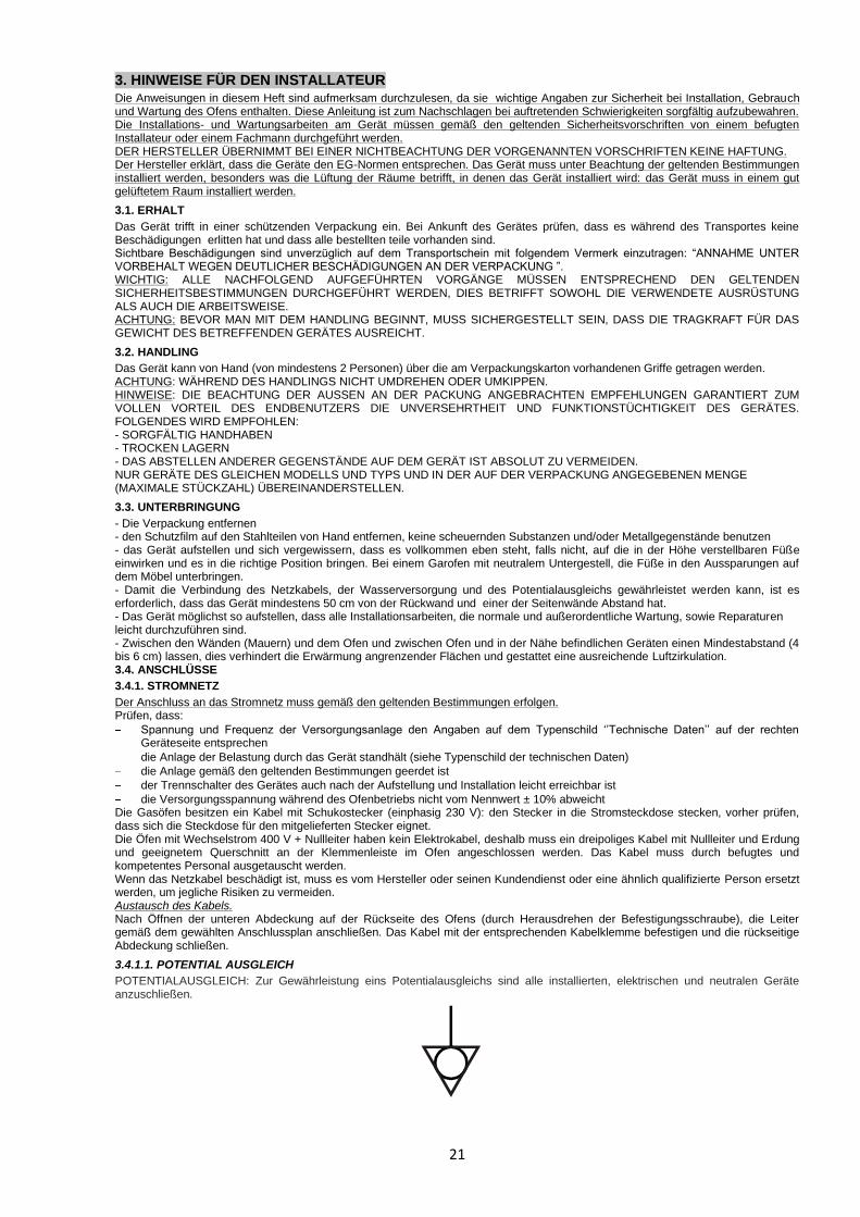
3.4.1.1. POTENTIAL AUSGLEICH
POTENTIALAUSGLEICH: Zur Gewährleistung eins Potentialausgleichs sind alle installierten, elektrischen und neutralen Geräte anzuschließen.

22
3.4.2. WASSERLEITUNG (KONVEKTION UND DIREKTDAMPF)
Zwischen Wasserleitung und Gerät sollte ein Absperrhahn angebracht werden. Das Gerät ist mit einem Gewindanschluss ¾” wie auch mechanischen Filter ausgerüstet. Zum Anschluss zur Wasserversorgung verwenden Sie ausschliesslich den Anschlusskit der mit dem Gerät zusammen geliefert wird, wobei das Gewindenutteil des mitgelieferten Rohrs, dem mechanischen Filter anschuschrauben ist. Zum Anschluss zur Wasserversorgung soll ausschliesslich den mit dem Ofen zusammen beigelieferte Kit verwendet werden . Vor der Installation des Versorgungsrohrs sollte man es mit laufendem Wasser innen von Rückständen oder Staub befreit werden. Wasserwerte: - Der empfohlene Druck am Wassereinlauf muss unter 200 kPa liegen. Bei höherem Druck muss ein Druckminderer installiert werden, der auf 200 kPa eingestellt ist. - Höchsttemperatur des Wassers etwa 30° C - Maximale Wasserhärte 5°F (um Kalkablagerungen zu vermeiden, die das Gerät schädigen) - Um jede Art von Mineralablagerungen zu verhindern, sollte ein Wasserenthärter benutzt werden. 3.4.3. ABLÄUFE
Wasser
Das für den Wasserablauf vorgesehene Rohr muss auf einem Material bestehen, dass die Temperatur des aus dem Ofen austretenden Wassers (90° C) aushält, es muss auf der Ofenrückseite angebracht und mit einer steifen oder flexiblen Leitung an einen Ablauf mit Siphon angeschlossen sein. Das Rohr muss dem Durchmesser der Ablauföffnung angepasst und einen Meter lang sein, es darf keine Biegungen oder Engstellen aufweisen und für einen leichteren Ablauf 20 cm tiefer als der Ablaufanschluss liegen.
Rauchgas
Der Rauchgasabzug des Gerätes befindet sich oben in Richtung der Rückwand: darauf achten, dass die Abzugskamine nicht verschlossen werden und sich vergewissern, dass der Ausstoß der Abzugskamine nicht Material oder Einrichtungsgegenstände trifft, die beschädigt werden könnten. Nach dem das Vorgenannte geprüft wurde, kann der Ofen unter einer Abzugshaube (mit Filter) oder unter einer Abzugsdecke aufgestellt werden.
4. GEBRAUCHSHINWEISE FÜR DEN ENDVERBRAUCHER NICHT VERSORGTE LEITERPLATTE In diesem Zustand sind sämtliche Displays und LED ausgeschaltet. Die Relais sind in ihrem Normalzustand ohne Versorgung. VERSORGTE LEITERPLATTE Sobald die Leiterplatte versorgt wird, führt sie einige Sekunden lang einen Lampentest aller LED und Displays aus, danach schaltet sie sich auf STANDBY. Durch Betätigung der Taste PHASEN (7) während des Lampentests werden zuerst die Version und danach die Revision der Leiterplatten-Firmware angezeigt. STATUS STAND-BY In diesem Zustand sind sämtliche Displays und LED ausgeschaltet; die Relais sind nicht erregt. Durch Betätigung des ENCODERS (10) schaltet sich die Leiterplatte auf STOPP. STATUS STOP In diesem Zustand ist die Leiterplatte für die Einstellung und den Start eines Garzyklus bereit. Die Benutzerschnittstelle sieht 3 direkte Zugangsfunktionen - PHASEN (7), FEUCHTIGKEIT MANUELL (9, LED 5) und START/STOPP (8, LED 6) - und 4 Funktionen mit Zugang über Encoder vor - TEMPERATUR (3), ZEIT (2), FEUCHTIGKEIT (1) und PROGRAMME (4). Sofern keine Alarme vorhanden sind und der Zyklus eingestellt wurde, startet die einfache Betätigung der Taste START/STOPP (8) den Garzyklus und stellt die Leiterplatte auf START. Wird die Taste START/STOPP (8) gedrückt gehalten, schaltet sich die Leiterplatte auf STANDBY. Auf STOPP zeigt das Display normaler Weise die in der Kammer gemessene Temperatur an, außer, es wird gerade ein Sollwert eingegeben oder angezeigt (Zeit, Kammer, Feuchtigkeit); andere mögliche Displayanzeigen werden in den folgenden Absätzen beschrieben. Durch Drehen oder Drücken des Encoders beginnt die LED ZEIT (2) zu blinken; durch weiteres Drehen läuft die blinkende LED zyklisch die 4 Funktionen durch, die über den Encoder erreichbar sind. Das Display zeigt den Sollwert der 3 Funktionen Temperatur, Zeit und Feuchtigkeit sowie den Code des eventuell aktiven Programms für die Funktion Programme an. Durch Drücken des Encoders wird die von der blinkenden LED angezeigte Funktion gewählt; in den folgenden Absätzen werden diese Funktionen detailliert beschrieben. Nachdem 5 Sekunden lang keine Taste betätigt wurde, schaltet sich der Funktionswahlmodus über Encoder ab. Sofern ein Alarm vorhanden ist, wird dieser durch Anzeige des entsprechenden Codes am Display und den Summer signalisiert. Bei der Betätigung irgendeiner Taste schaltet sich der Summer ab. Weitere Details sind im Kapitel DIAGNOSE zu finden. Die Leiterplatte kehrt nach 10 Minuten, ohne dass irgendwelche Einstellungen vorgenommen werden, wieder auf STANDBY zurück. GARZYKLUS Jeder Garzyklus (manuell oder Programm) kann aus maximal 3 Phasen bestehen; jede Phase benötigt 3 Sollwerte: Temperatur, Zeit und Feuchtigkeit. Sollte ein Programm laufen, wird dies von der LED PROGRAMME (4) angezeigt. Die Anzahl der leuchtenden LED Phasen (11: 1-2-3) zeigt die Anzahl der Phasen des gewählten Zyklus an und die blinkende LED Phase bedeutet, welche Phase derzeit angezeigt wird. Die ständig leuchtende LED FEUCHTIGKEIT (1) zeigt an, dass ein anderer Sollwert für die Feuchtigkeit als 0 eingestellt ist; im gegenteiligen Fall leuchtet die LED nicht. Bei jedem Einschalten (Übergang von STANDBY auf STOPP) lädt der Ofen den zuletzt gespeicherten manuellen Zyklus. Beim ersten Einschalten wird der manuelle Default-Zyklus durch eine Phase mit einem durch einen Parameter vorgegebenen Preset der Kammer, nicht eingegebener Garzeit und nicht aktivierter Feuchtigkeit definiert; dieser Zyklus kann nicht aktiviert werden, da die Garzeit vom Benutzer eingestellt werden muss. Beim Versuch, den Zyklus zu starten, ertönt der Summer mit einem tiefen Ton („boop“), was bedeutet, dass der versuchte Vorgang nicht zulässig ist.

23
EINSTELLUNG DER TEMPERATURE Den Encoder so weit drehen, bis die blinkende LED auf die Funktion TEMPERATUR (3) gebracht wird. Das nicht blinkende Display zeigt den derzeitigen Sollwert der Temperatur an. Durch Drücken des Encoders (10) beginnt das Display zu blinken und die LED (3) leuchtet ständig; das bedeutet, dass der Sollwert der Temperatur geändert wird. Durch Drehen des Encoders (10) wird der Sollwert der Temperatur innerhalb der beiden, von Parametern festgelegten Grenzen geändert; durch Drücken des Encoders wird der gewählte Wert bestätigt. Wir der Encoder (10) bis zu Beginn der Skala gedreht, kann eine im Datensatz „PAU“ am Display angezeigte Pausephase gewählt werden. Nachdem 5 Sekunden lang keine Taste betätigt wurde, wird die Änderung des Temperatur-Sollwerts abgebrochen und das System kehrt zur Auswahl der Funktion über Encoder zurück (nur die LED blinkt), wobei der gewählte Wert nicht bestätigt wird. EINSTELLUNG DER ZEIT Für die Eingabe der Garzeit ist die Funktion ZEIT (2) zu wählen. Das Display zeigt den Sollwert der Garzeit im Format h.mm an, sie kann zwischen 0.01 und 9.59 eingestellt werden. Ist die eingegebene Garzeit unendlich, zeigt das Display „Inf“ an, während das Display bei nicht eingegebener Zeit (wie beim Default-Zyklus, der beim Einschalten verwendet wird, oder bei der Erstellung einer neuen Phase) „---“ anzeigt. Durch Drücken des Encoders (10) beginnt das Display zu blinken und die LED leuchtet ständig; das bedeutet, dass der Sollwert der Garzeit geändert wird. Wird der Encoder (10) beginnend vom Skalenanfang (komplette Drehung gegen den Uhrzeigersinn) im Uhrzeigersinn gedreht, werden der Reihe nach folgende Einstellungen angezeigt: „---”, „Inf” und danach die Zeiten von 0.01 bis 9.59. Das Durchlaufen erfolgt zyklisch, d. h. nach 9.59 kehrt wieder „---”. Durch Drücken des Encoders (10) wird der gewählte Wert bestätigt; nachdem 5 Sekunden lang keine Taste betätigt wurde, wird die Änderung des Zeit-Sollwerts abgebrochen und das System kehrt zur Auswahl der Funktion über Encoder (10) zurück (nur die LED blinkt), wobei der gewählte Wert nicht bestätigt wird. EINSTELLUNG FEUCHTIGKEIT Die Funktion FEUCHTIGKEIT (1) über den Encoder (10) hervorheben, sodass die dazugehörige LED blinkt; das Display zeigt den Sollwert der Feuchtigkeit. Durch Drücken des Encoders (10) beginnt das Display zu blinken und die LED leuchtet ständig; das bedeutet, dass der Sollwert der Feuchtigkeit geändert wird. Durch Drehen des Encoders (10) kann ein Wert zwischen 0 und 10 gewählt werden; die Bestätigung erfolgt durch Drücken des Encoders (10). Nachdem 5 Sekunden lang keine Taste betätigt wurde, wird die Änderung des Feuchtigkeits-Sollwerts abgebrochen und das System kehrt zur Auswahl der Funktion über Encoder zurück (nur die LED blinkt), wobei der gewählte Wert nicht bestätigt wird. GARZYKLUS PHASEN Jeder Garzyklus, gleich, ob es sich um ein Programm oder einen manuellen Zyklus handelt, kann aus maximal 3 Phasen bestehen. Die Anzahl der leuchtenden LED der Phasen zeigt, wie viele Phasen im gewählten Programm vorhanden sind (einschließlich der Pausephasen und der Phasen mit nicht eingegebener Garzeit); die blinkende LED zeigt an, welche Zyklusphase derzeit angezeigt wird. Die gewählte Phase kann durch Drücken der Taste PHASEN (7) geändert werden. Sofern sich das System nicht im Funktionswahlmodus über Encoder befindet, wird durch Drücken der Taste PHASEN (7) 3 sec lang der Zeit-Sollwert angezeigt (die LED ZEIT 2 leuchtet auch auf), um die Ermittlung der eventuellen Phasen ohne Zeiteinstellung zu vereinfachen. Bei jeder längeren Betätigung der Taste PHASE (7) wird nach der blinkenden Phase eine neue Phase eingefügt; diese neue Phase ist demnach die derzeit gewählte Phase und blinkt. Die auf die ausgewählte Phase folgenden Phasen verschieben sich um eine Position, um der neuen Phase Platz zu machen. Nach der dritten Phase kann keine andere Phase angelegt werden. Sofern bereits 3 Phasen vorhanden sind, wird die dritte Phase durch die Erstellung einer neuen Phase gelöscht. Die zusätzlichen Phasen haben ein durch einen Parameter vorgegebenes Preset der Kammer, keine eingegebene Garzeit und nicht aktivierte Feuchtigkeit. Die Garphasen ohne eingegebene Garzeit werden beim START nicht ausgeführt und es wird auf die folgende eingegebene Phase übergegangen. Damit ein Garzyklus gestartet wird, muss zumindest eine seiner Phasen eine eingestellte Zeit haben. Um die aktuelle Phase zu löschen, die Funktion ZEIT (2) wählen und den Encoder (10) auf Skalenbeginn drehen, sodass „---” erscheint; durch die Bestätigung dieses Werts wird die gewählte Phase gelöscht. Die folgenden Phasen verschieben sich um eine Position, um die fehlende Position zu besetzen; sollte die Zeit eines aus nur einer Phase bestehenden Zyklus auf „---” eingestellt werden, wird diese nicht gelöscht, aber der Zyklus kann solange nicht gestartet werden, bis eine gültige Phase eingegeben wird. GARPROGRAMMEN Der Ofen kann die Einstellungen von 20 Garprogrammen und einen manuellen Zyklus speichern. Werkseitig wird der Ofen mit allen Programmen auf Default-Zyklus eingestellt: 1 Phase mit durch einen Parameter vorgegebenem Preset der Kammer, keine eingegebene Garzeit und nicht aktivierte Feuchtigkeit. Jedes Programm kann höchstens aus drei Phasen bestehen und speichert die normaler Weise in einem manuellen Garzyklus verwendeten Einstellungen: - Sollwert Temperatur - Sollwert Zeit - Sollwert Feuchtigkeit Jedes Programm kann mit diesen Änderungen variiert und gestartet werden. Diese Änderungen werden jedoch nicht automatisch gespeichert, sondern erfordern eine Handlung des Benutzers. Zum Speichern der neuen Einstellungen ist der Encoder (10) 2 Sekunden lang gedrückt zu halten (sofern kein Sollwert geändert wird); die Speicherung wird durch den Summer bestätigt. Zur Auswahl eines Programms den Encoder (10) so weit drehen, bis die LED PROGRAMME (4) blinkt. Das Display zeigt den Code des eventuell aktiven Programms im Format P01 - P20 oder „---” an, sofern derzeit ein manueller Garzyklus läuft. Durch Drücken des Encoders (10) beginnt das Display zu blinken und die LED (4) leuchtet ständig; durch Drücken des Encoders (10) kann ein Programm zwischen P01 und P20 gewählt werden; durch Drehen auf Skalenbeginn (vor P01) wird „---” angezeigt, was den Austritt aus dem Programmmodus und die Auswahl des manuellen Betriebsmodus anzeigt. Durch Drücken des Encoders wird das gewünschte Programm gewählt; das Display blinkt nicht mehr, während die LED (4) der Programme wieder zu blinken beginnt, was bedeutet, dass die Sollwerte des Programms durch Drehen des Encoders (10) gewählt werden können. Um die Programmwahl wieder rückgängig zu machen und auf den manuellen Betriebsmodus zurückzukehren, den Eintrag „---” im Programmmenü wählen. Wenn ein Programm gewählt wurde, kann dieses gleich wie im manuellen Betriebsmodus geändert werden. Die vorgenommenen Änderungen werden nicht automatisch gespeichert, aber der Garzyklus kann mit dem geänderten Programm gestartet werden.

24
ZYKLUSSTART Bei Betätigung der Taste START/STOPP (8) wird der derzeitig gewählte Garzyklus (manuell oder Programm) gestartet und der Ofen auf START gestellt. Damit ein Zyklus auch gestartet werden kann, muss er zumindest aus einer Phase mit eingegebenem Zeit-Sollwert bestehen. Die LED START/STOPP (6) leuchtet ständig und es werden die entsprechenden Einstellungen aktiviert. Während der Eingabe eines Sollwerts (Temperatur, Zeit, Feuchtigkeit) bzw. über das Auswahlmenü eines Programms kann kein Garzyklus gestartet werden. START MODE Der Status START der Leiterplatte startet den gewählten Garzyklus und beginnt die entsprechenden Regelungen. Die LED START/STOPP (6) leuchtet ständig. Normaler Weise zeigt das Display während des Zyklus die bis zum Ende der Phase fehlende Zeit (mit blinkendem Punkt). Durch Drücken des Encoders (10) kann die in der Kammer gemessene Temperatur 5 sec lang angezeigt werden. Zum Ändern der Sollwerte ist wie bei STOPP vorzugehen: Den Encoder (10) bis zur Auswahl der gewünschten Funktion (Temperatur, Zeit, Feuchtigkeit) drehen, den Encoder (10) drücken, den gewünschten Wert wählen und durch Drücken des Encoders (10) bestätigen. Nachdem 5 Sekunden lang keine Taste betätigt wurde, wird der gewählte Wert nicht bestätigt. Auf jeden Fall werden die Änderungen nicht gespeichert und werden nur für den laufenden Zyklus verwendet; bei Zyklusende werden sie gelöscht. Die Programmänderungen können im START-Modus nicht gespeichert werden. Die Phasen ohne Zeiteinstellung werden nicht ausgeführt. Der Summer signalisiert das Erreichen des Temperatur-Sollwerts der ersten Phase. Durch Drücken der Taste FEUCHTIGKEIT MANUELL (9) leuchtet die entsprechende LED (5) auf und der Kammer wird ungefähr 10 sec Dampf zugeführt. Wird die Taste START/STOPP (8) gedrückt gehalten, beendet die Leiterplatte den Garvorgang und schaltet sich auf STOPP; dies wird durch den Summer signalisiert. Wird die Taste START/STOPP (6) gedrückt (einmaliges Drücken) oder die Tür geöffnet, schaltet sich die Leiterplatte auf VORÜBERGEHENDER STOPP. Wird die Taste PHASEN (7) gedrückt gehalten, wird die laufende Phase beendet und zur nächsten Phase übergegangen. Der Summer gibt einen längeren Ton ab; sofern dies die letzte Garphase gar, wird die Garzeit beendet und der Ofen schaltet sich auf STOPP. Die ausgeführte Phase wird durch die blinkende LED PHASEN (7) angezeigt. Es ist nicht möglich, während eine Phase durchgeführt wird, weitere Phasen anzuzeigen, zu ändern, hinzuzufügen oder zu löschen. Auch der Zugriff auf das Programmmenü (4) ist nicht möglich (es kann aber der Code des ausgeführten Programms angezeigt werden). Bei Zyklusende ertönt der Summer und die Leiterplatte stellt sich auf STOPP (der Summer wird durch Betätigung einer Taste oder durch Öffnen der Tür quittiert). STATUS VORÜBERGEHENDER STOPP Im Status VORÜBERGEHENDER STOPP werden die Regelungen aufgehoben und der Lüfter ausgeschaltet. Die Zeitschaltuhr des zeitgeregelten Zyklus wird unterbrochen und der Punkt am Display blinkt nicht mehr. Die LED START/STOPP blinkt. Durch erneutes Drücken der Taste START/STOPP (8) wird der Garzyklus bei geschlossener Tür wieder aufgenommen. Durch Schließen der Tür wird der Garzyklus dann wieder aufgenommen, wenn die Unterbrechung infolge der Öffnung derselben eingetreten ist (ohne dass die Taste START/STOPP gedrückt wurde). Wird die Taste START/STOPP länger gedrückt, wird der Garvorgang beendet und die Leiterplatte schaltet sich auf STOPP. Die Änderungen am laufenden Zyklus können wie im START-Modus vorgenommen werden.
TÜR GEÖFFNET Ist beim START die Tür geöffnet, wird auf VORÜBERGEHENDER STOPP geschaltet und die LED der Taste START/STOPP blinkt. Es werden sämtliche Relais deaktiviert, ausgenommen das Relais LICHT und das Relais LÜFTER RICHTUNG, die ihren Status beibehalten. Der Garvorgang wird unterbrochen, bis die Tür wieder geschlossen wird. MANGELNDE SPANNUNG Sollte die Versorgungsspannung über einen ausreichenden Zeitraum hinweg unterbrochen werden, dass die Leiterplatte ausgeschaltet wird, führt die Steuerung bei erneuter Stromzufuhr einen Lampentest durch und stellt sich auf STOPP, unabhängig von dem Status, in dem sie sich zum Zeitpunkt der Unterbrechung befand. Für den Spannungsausfall gibt es keine Alarme.

25
5. BEDIENBLENDE UND LEGENDE
1
2
3
2 3 4 6
7 8
1
2
3
1 2 34 5 6
7 9
KONVEKTION
KONVEKTION UND DAMPF
810
10
11
11
UMIDITÀ / HUMIDITY
AUMENTO MANUALE DELL‟UMIDITÀ / MANUAL INCREASE OF HUMIDITY
LUFTFEUCHTIGKEIT / HUMIDITÉ
MANUELLE LUFTFEUCHTIGKEITSTEIGERUNG / AUGMENTATION MANUEL DE L‟HUMIDITÉ
TEMPO DI COTTURA / COOKING TIME
START - STOP - PAUSA / START - STOP - PAUSE
KOCHZEIT / TEMPS DE CUISSON
START - STOP - PAUSE / START - STOP - PAUSE
TEMPERATURA DI COTTURA / COOKING TEMPERATURE
FASE DI COTTURA / COOKING PHASES
KOCHTEMPERATUR / TEMPÉRATURE DE CUISSON
KOCH PHASEN / PHASES DE CUISSON
MENÙ-SALVA / MENU-SAVE MENÜ-SPEICHERN / MENU-ENREGISTER
1
2
3
4
5
6
7
89
10
SELEZIONE-CONFERMA / SELECTION-CONFIRMAUSWAHL-BESTÄTIGUNG/ SELECTION-CONFIRMIR
11 FASE DI COTTURA / COOKING PHASESKOCH PHASEN / PHASES DE CUISSON
1
2
3

26
6. NORMALE WARTUNG
Alle Wartungsarbeiten dürfen nur von fachlich ausgebildetem Personal durchgeführt werden. Vor Beginn eines Wartungseingriffes muss das Gerät ausgeschaltet und vom Stromnetz (bei einem Gasofen muss der Gashahn geschlossen werden) und der Wasserleitung abgetrennt werden. OFENREINIGUNG : Nach Beendigung des täglichen Betriebs den Ofen mit geeigneten Mitteln reinigen: 1- lauwarme und neutrale Seifenlauge oder neutrale Reiniger benutzen 2- mit Wasser gründlich nachspülen 3- sorgfältig abtrocknen Keine Spachteln, Scheuerbürsten oder andere Werkzeuge benutzen: sie könnten die Stahlfläche beschädigen und eisenhaltige Ablagerungen hinterlassen, die mit der Zeit zur Rostbildung führen. Den Ofen nicht mit einem Wasserstrahl abwaschen. Keine Produkte auf Chlorbasis (Natriumhypochlorit, Chlorwasserstoffsäure), auch nicht mit Wasser verdünnt, zum Reinigen der Stahlteile benutzen. Nach jedem spezifischen Garvorgang und vor dem nächsten sollten eventuelle Lebensmittelreste (Fett oder Saft) beseitigt werden. Für die gründliche Reinigung des Ofens sind geeignete Produkte zu verwenden: falls Speisereste oder Fett in schwer erreichbaren Ecken zurückbleiben könnte dies langfristig das Gerät schädigen und im Garraum zu unerwünschter Rauch- und Geruchsbildung führen, schlimmstenfalls können die Luftklappen verstopfen oder mechanische Bewegungen beeinträchtigt werden. Wenn das Gerät für längere Zeit nicht benutzt wird, folgende Vorkehrungen treffen: 1- das Gerät mit der Taste (OFF) ausschalten 2- die Hähne des Strom-, Wasser- und Gasanschlusses (wo vorhanden) schließen 3- die Tür des Gerätes etwas offen lassen, damit Luft eintreten kann und sich kein Kondensat bilden kann oder Gerüche im Garraum entstehen 4- mit einem Tuch einen schützenden Vaselineölfilm auf alle Edelstahlflächen auftragen ES WIRD DRINGEND GERATEN, DASS GERÄT REGELMÄSSIG (MINDESTENS EINMAL PRO JAHR) DURCH EINEN SPEZIALISIERTEN TECHNIKER PRÜFEN ZU LASSEN.
7. ENTSORGEN DER VERPACKUNG
Das Verpackungsmaterial entsorgen, in dem man es den Normen entsprechend einer Sammelstelle oder spezialisierten Recyclingunternehmen zuführt.
8. BESEITIGUNG UND VERSCHROTTUNG DES GERÄTES
Bei der Beseitigung des Gerätes muss es vor der Verschrottung durch Abtrennen des Versorgungskabel funktionsunfähig gemacht werden. Alle gefährlichen Teile müssen entfernt und Schloss, Scharnier oder andere Systeme unbrauchbar gemacht werden. WICHTIG: FÜR DIE VERSCHROTTUNG DIESER GERÄTEART MÜSSEN DIE ÖRTLICHEN BESTIMMUNGEN BEACHTET WERDEN.
27
FRENCH Sommaire 1. RECOMMANDATIONS 28
1.1. RECOMMANDATIONS GÉNÉRALES 28
1.2. RECOMMANDATIONS TECHNIQUES GÉNÉRALES 28
1.3. RECOMMANDATIONS GÉNÉRALES POUR L'UTILISATION 28
2. CARACTÉRISTIQUES TECHNIQUES GÉNÉRALES 29
2.1. DONNÉES TECHNIQUES 29
3. RECOMMANDATIONS POUR L‟INSTALLATEUR 30
3.1. RÉCEPTION 30
3.2. MOVIMENTATION 30
3.3. EMPLACEMENT 30
3.4. RACCORDEMENTS 30
3.4.1. RÉSEAU ÉLECTRIQUE 30
3.4.1.1. RACCORDEMENT ÉQUIPOTENTIEL 30
3.4.2. RÉSEAU HYDRAULIQUE 31
3.4.3. ÉVACUATIONS 31
4.INDICATIONS D'UTILISATION POUR L'UTILISATEUR FINAL 31
5. TABLEAU DE COMMANDE ET LÉGENDE 33
6.ENTRETIEN ORDINAIRE 34
7. ÉLIMINATION DE L'EMBALLAGE 34
8. ÉLIMINATION ET MISE AU REBUT DE L'APPAREIL 34
9. SCHÉME D‟INSTALLATION 35
10. SCHÉMAS ÉLECTRIQUES 36

28
1. RECOMMANDATIONS
1.1 RECOMMANDATIONS GÉNÉRALES
Le manuel présent a été réalisé pour permettre l'installation, la mise au point et l'entretien de l'appareil, de manière correcte. Il est absolument important que les recommandations contenues dans le manuel présent soient lues attentivement car elles fournissent d'importantes indications concernant la sécurité d'installation, d'utilisation et d'entretien. Le manuel présent et le schéma électrique doivent être conservés avec soin et mis à disposition de l'opérateur (installateur, technicien et utilisateur final) pour toute consultation ultérieure. L'appareil doit être installé, testé et assisté par un personnel qualifié conformément aux normes en vigueur. L'appareil a été conçu et réalisé pour la cuisson de produits alimentaires et pour la régénération d'aliments congelés ou surgelés, et il devra donc être destiné uniquement à l'utilisation pour laquelle il a expressément été conçu. Toute utilisation différente de celle qui est spécifiée ne comporte, pour le fabricant, aucun engagement ou lien d'aucun genre. Le producteur décline toute responsabilité avec déchéance de la garantie, en cas de modifications électriques et/ou mécaniques. Les altérations en général, non autorisées expressément et qui ne respectent pas les indications du manuel présent, font déchoir la garantie. Pour une éventuelle réparation, s'adresser exclusivement à un centre d'assistance technique agréé par le fabricant et demander l'utilisation de pièces de rechange originales. En cas de doute, ne pas utiliser l'appareil et s'adresser au personnel professionnellement qualifié. Le non-respect des indications ci-dessus peut compromettre la sécurité de l'appareil. Vérifier que les caractéristiques du réseau électrique sont conformes aux données reportées sur la plaque de matricule. Il materiale di imballaggio (sacchetti in plastica, polistirolo espanso, chiodi, ecc.) in quanto potenziale fonte di pericolo deve essere tenuto fuori dalla portata dei bambini e correttamente riciclato secondo le norme locali in vigore.
1.2. RECOMMANDATIONS TECHNIQUES GÉNÉRALES
- Chaque appareil est équipé d'une plaque d'identification, placée sur le côté droit, en bas qui identifie le modèle et les données techniques principales: LIRE LES DONNÉES REPORTÉES AVANT D'EFFECTUER L'INSTALLATION. - L‟appareil doit être installé dans une pièce aérée et ventilée. - L‟appareil doit être utilisé uniquement par le personnel formé de manière adéquate. - L'appareil doit être hors de portée des enfants. - L‟utilisation de l'appareil a besoin d'une surveillance constante. - Quand le four est en marche, faire attention aux surfaces externes qui se réchauffent: éviter de les toucher. - Demander à l'installateur d'installer un adoucisseur d'eau : s'il est absent, l'appareil pourrait être gravement endommagé par le calcaire. - L'on conseille l'installation d'un siphon au niveau de la sortie de l'eau d'évacuation du four (pour le models convection et vapeur)
1.3. RECOMMANDATIONS GÉNÉRALES D'UTILISATION
A la première utilisation : - Dans la phase de première utilisation, faire attention que le manuel d'instruction, les sachets en plastique et les autres objets ont bien été enlevés de la chambre de cuisson du four. - A la première utilisation du four, l'on conseille de le faire fonctionner à vide pendant 30-40 minutes à une température de 200° C, afin d'éliminer les odeurs désagréables des matériaux utilisés pour l'isolation thermique ou d'autres résidus de production. Le nettoyage : - Avant d'allumer le four pour la première fois, nettoyer soigneusement la chambre de cuisson en utilisant des produits non corrosifs (alcalins) pour ne pas endommager les surfaces. - Éviter d'utiliser des matériaux et des produits abrasifs pour ne pas rayer les surfaces. - A la fin de l'utilisation quotidienne, nettoyer l'intérieur de la chambre de cuisson et l'extérieur de l'appareil : cela prolongera la durée de vie de l'appareil et assurera son bon fonctionnement. - Ne pas utiliser de jets d'eau sous pression pour le nettoyage du four. - Éviter les opérations de salage à l'intérieur de la chambre de cuisson pour ne pas avoir d'incrustations ou de dépôts de sel. En cas de dépôts, rincer immédiatement et essuyer avec soin. Précautions pour l'utilisation : - Après avoir cuisiné à la vapeur, ouvrir avec précaution la porte de four, pour éviter d'entrer en contact soudain et direct avec la vapeur à haute température, qui est restée dans la chambre de cuisson. - Le non-respect de cette précaution pourrait être dangereux pour l'opérateur. - Il est interdit d'obstruer les prises d'air et tous les autres orifices existant sur le four, dans le cas contraire, on compromet le fonctionnement en sécurité de l'appareil. - Pour éviter des brûlures, ne pas utiliser de récipients contenants des liquides ou des aliments qui peuvent devenir fluides lors de cuisson s„ ils sont placés aux niveaux qui ne permettent pas le contrôle visuel direct. Panne et élimination : - Désactiver l'appareil en cas de panne ou de mauvais fonctionnement. - En cas d'élimination de l'appareil, interrompre et débrancher les lignes d'alimentation en gaz (si elle est présente), en énergie électrique et en eau.

29
2. CARACTÉRISTIQUES TECHNIQUES GÉNÉRALES 2.1. DONNÉES TECHNIQUES
620x630x500
500x380x300
3
3,2
0,31
40
620x630x650
500x380x450
3,35
3,55
0,40
48
780x680x500
3,35
3,55
230V 1N 50Hz
0,39
48
780x680x650
660x430x450
6
6,3
400V 3N 50Hz
0,50
62
230V 1N 50Hz 230V 1N 50Hz
kW
TOT.
kW
CONVECTION
CONVECTION+
VAPEUR
DIMENSIONS EXTÉRIEURES
LxPxH (mm)
CAPACITÉ
POIDS BRUT
(Kg)
VOLUME EMBALLAGE
(m³)
DIMENSIONS
INTERIEURESLxPxH (mm)
AFO 600 AFO 602 AFO 603
AFO 604 AFO 605 AFO 606 AFO 607
N° 3 GN 1/1 et 400X600
660x430x300
AFO 601
N° 5 GN 1/1 et 400X600
N° 3 2/3 GN 1/1 et
440x350 mm
N°5 2/3 GN 1/1 et
440x350 mm
FOUR+
SUPPORT+HOTTE
AxCxB(mm)
TENSION
790x1000x1630 790x1000x1780 630x950x1630 630x950x1780
PROFONDITÉ AVEC PORTE OUVERTE
AFO 600 1030 mm
AFO 601 1180 mm
AFO 602 980 mm
AFO 603 1130 mm
AFO 604 1030 mm
AFO 605 1180 mm
AFO 606 980 mm
AFO 607 1130 mm
B
A C

30
3. RECOMMANDATIONS POUR L‟INSTALLATEUR Lire attentivement les instructions contenues dans ce manuel car elles peuvent fournir d'importantes indications concernant la sécurité de l'installation, l'utilisation et l'entretien du four. Conserver soigneusement ce manuel afin de pouvoir le consulter en cas de problèmes. Les opérations d'installation et d'entretien de l'appareil devront être effectuées par un installateur agréé ou par des spécialistes, conformément aux normes de sécurité en vigueur. LE FABRICANT DÉCLINE TOUTE RESPONSABILITÉ EN CAS DE NON-RESPECT DES NORMES CI-DESSUS. Le fabricant déclare que les appareils sont conformes aux normes CE. L‟installation devra être effectuée en respectant les normes en vigueur, en particulier celles qui concernent l'aération des locaux où sera installé l'appareil : installer le four dans un local bien aéré.
3.1. RÉCEPTION
L‟appareil est livré, protégé par un emballage. Contrôler, à l'arrivée de l'appareil, qu'il n'ait pas subi de dommages pendant le transport et qu'il soit complet dans toutes ses parties, dont à la commande. En cas de dommages visibles, noter immédiatement sur le document relatif au transport, le dommage en reportant le texte : “RETIRÉ SOUS RÉSERVE POUR D'ÉVIDENTS DOMMAGES DE L'EMBALLAGE". IMPORTANT : TOUTES LES OPÉRATIONS CITÉES CI-DESSOUS DOIVENT ÊTRE EFFECTUÉES CONFORMÉMENT AUX NORMES DE SÉCURITÉ EN VIGUEUR, AUSSI BIEN EN CE QUI CONCERNE L'ÉQUIPEMENT UTILISÉ QUE POUR LES MODALITÉS OPÉRATIONNELLES. ATTENTION : AVANT D'EFFECTUER LES OPÉRATIONS DE MANUTENTION, S'ASSURER QUE LA CAPACITÉ DE LEVAGE EST ADAPTÉE AU POIDS DE L'APPAREIL EN QUESTION.
3.2. MANUTENTION
L‟équipement peut être déplacé manuellement (par au moins deux personnes) à l‟aide de poignées situées sur le carton d‟emballage. ATTENTION : AU COURS DE LA MANUTENTION NE PAS RETOURNER OU RENVERSER. RECOMMANDATIONS : LE RESPECT DES RECOMMANDATIONS REPORTÉES SUR LE CÔTÉ EXTERNE DE L'EMBALLAGE EST LA GARANTIE DE L'INTÉGRITÉ PHYSIQUE ET FONCTIONNELLE DE L'APPAREIL, À L'AVANTAGE DE L'UTILISATEUR FINAL. IL EST DONC RECOMMANDÉ DE : - DÉPLACER EN FAISANT ATTENTION - GARDER AU SEC - ÉVITER ABSOLUMENT DE GERBER D'AUTRES OBJETS SUR L'APPAREIL. GERBER SEULEMENT AVEC DES APPAREILS DU MÊME MODÈLE ET TYPE ET DANS LES QUANTITÉS (N° PIÈCES MAXIMUM) REPORTÉES SUR L'EMBALLAGE.
3.3. EMPLACEMENT
- Enlever l'emballage - enlever manuellement la pellicule de protection sur les parties en acier, en évitant d'utiliser des substances abrasives et/ou des objets métalliques - placer l'appareil en s'assurant qu'il soit parfaitement à niveau (C), sinon agir sur les pieds à hauteur réglable afin qu'il soit positionné correctement. Dans le cas de four+petit meuble neutre, loger les pieds dans les espaces créés à cet effet sur le meuble. - afin de permettre la connexion du câble d'alimentation, l'approvisionnement en eau et égalisation des potentiels il est nécessaire que l'équipement est au moins 50 cm du mur arrière et l'une des parois latérales. - essayer de placer l'appareil afin que toute opération d'installation, d'entretien ordinaire et extraordinaire, ainsi que les opérations de réparation, soit facile à effectuer. - maintenir un espace minimum entre les murs et le four et entre le four et les appareils qui lui sont proches (de 4 à 6 cm), cela pour éviter le réchauffement des surfaces adjacentes et pour permettre une circulation adéquate de l'air.
3.4. RACCORDEMENTS
3.4.1. RÉSEAU ÉLECTRIQUE Le raccordement au réseau électrique doit être effectué conformément aux normes en vigueur. Vérifier que :
la tension et la fréquence de l'installation d'alimentation correspondent à ce qui est indiqué sur la plaque „‟données techniques‟‟ placée sur le côté droit de l'appareil
l‟installation peut supporter la charge de l'appareil (voir la plaque avec les données techniques)
l‟installation est équipée de la mise à terre conformément aux normes en vigueur
le sectionneur du four peut facilement être atteint même après avoir positionné et installé l'appareil
la tension d'alimentation, quand le four est en marche, ne s'écarte pas de la valeur nominale de ± 10% Les fours à gaz sont équipés d'un câble avec fiche Schuko (monophasé 230 V): insérer la fiche dans la prise électrique après avoir vérifié que la prise soit adaptée à la fiche utilisée. Les fours triphasés 400 V + Neutre, ne sont pas équipés de câble électrique, donc, il est nécessaire de brancher au bornier interne du four un câble tripolaire plus neutre plus mise à terre, de section adaptée. Le remplacement du câble doit être effectué par le personnel agréé et compétent.
Remplacement du câble. Après avoir ouvert le couvercle inférieur, placé dans la partie arrière du four (en dévissant la vis de fixation), brancher les conducteurs selon le schéma de branchement choisi. Fixer le câble à l'aide du serre-câble prévu à cet effet et puis, fermer le couvercle arrière. Si le câble d'alimentation est endommagé, il doit être remplacé par le fabricant ou son agent de service ou une personne qualifiée afin d'éviter tout risque. 3.4.1.1. RACCORDEMENT ÉQUIPOTENTIEL RACCORDEMENT ÉQUIPOTENTIEL Il est nécessaire pour le raccordement de tous les équipements (électriques et neutres) présents dans l‟installation à fin de garantir un raccordement équipotentiel.

31
3.4.2. RÉSEAU HYDRAULIQUE (CONVECTION+VAPEUR) Entre le réseau hydraulique et l'appareil, il est préférable de placer un robinet d'arrêt. L‟appareil est équipé d‟un branchement mâle ¾“ et un filtre mécanique. N‟utiliser Avant d'installer le tuyau d'alimentation, l'on conseille de faire écouler à l'intérieur de l'eau courant afin de le nettoyer d'éventuels résidus ou de poussière. Données de l'eau : - La pression conseillée pour l'eau en entrée doit être inférieure à 200 kPa. Pour des pressions supérieures, il faut installer un réducteur de pression calibré à 200 kPa. - La température maximale de l'eau est d'environ 30° C - la dureté maximale 5°F (afin d'éviter les incrustations calcaires, qui endommagent l'appareil) - l'on conseille d'utiliser un adoucisseur pour l'eau afin d'éviter tout dépôt de minéraux dans le four. 3.4.3. ÉVACUATIONS Eau Le tuyau prévu pour l'eau d'évacuation, doit être en un matériau en mesure de supporter la température de l'eau en sortie du four (90° C), il doit être positionné derrière le four et raccordé à un système d'évacuation siphonné par un conduit rigide ou flexible. Le tuyau aura un diamètre dimensionné par rapport au diamètre de l'orifice d'évacuation et une longueur d'un mètre, sans coudes ou étranglements, et, pour faciliter l'écoulement, il doit se trouver à 20 cm au-dessous du raccord d'évacuation. Fumées L'évacuation des fumées se trouve sur l'appareil, en haut vers le panneau arrière : attention de ne pas obstruer les cheminées d'évacuation et contrôler que les cheminées ne libèrent pas la fumées vers des matériaux ou des meubles qui pourraient s'endommager. Après avoir vérifié tout cela, le four peut être positionné sous une hotte aspirante (équipée de filtre) ou sous un plafond aspirant.
4. INDICATIONS D'UTILISATION POUR L'UTILISATEUR FINAL
FICHE NON ALIMENTÉE Dans cet état, tous les écrans et LED sont éteints. Les relais se trouvent dans leur état normal sans alimentation. ALIMENTATION DE LA CARTE À peine alimentée, la fiche effectue un essai de lampes de toutes les DEL et de tous les écrans pendant quelques secondes ; après cela, elle passe à l‟état d‟ATTENTE. Si l‟on appuie sur la touche PHASE (7), la version et la révision du micrologiciel sont affichées pendant l‟essai des lampes. ÉTAT “STAND-BY” Dans cet état, tous les écrans et DEL sont éteints et les relais ne sont pas excités. Si l‟on appuie sur ENCODER (10), la fiche passe à l‟état d‟ARRÊT. ÉTAT „‟STOP‟‟ Dans cet état, la fiche est prête pour le réglage et le lancement d‟un cycle de cuisson. L‟interface utilisateur a été conçue pour trois fonctions à accès direct : PHASE (7), HUMIDITÉ MANUELLE (9, DEL 5) et MARCHE/ARRÊT (8, DEL 6) ainsi que 4 fonctions depuis l‟ENCODER : TEMPÉRATURE (3), TEMPS (2), HUMIDITÉ (1) ET PROGRAMMES (4). En l‟absence d‟alarmes et avec un cycle sélectionné, la touche START/STOP [MARCHE/ARRÊT] (8) lance le cycle de cuisson et met la fiche en état de MARCHE. Si l‟on maintient la touche START/STOP (8) appuyée, la fiche passe à l‟état d‟ATTENTE. À l‟arrêt, l‟écran affiche normalement la température mesurée dans la chambre, à moins que l‟on ne soit pas en train de régler ou d‟afficher un point de réglage (temps, chambre, humidité) ; d‟autres affichages possibles pour l‟écran seront détaillés dans les paragraphes suivants. Si l‟on tourne et appuie sur l‟ENCODER, la DEL TEMPS (2) commence à clignoter ; si l‟on continue à le tourner, la DEL clignotante fait défiler cycliquement les quatre fonctions avec accès depuis l‟ENCODER. L‟écran affiche le réglage pour les 3 fonctions de température, de temps et d‟humidité et le code de l‟éventuel programme actif pour la fonction de programmes. Si l‟on appuie sur l‟ENCODER, il est possible de sélectionner la fonction mise en évidence par la DEL clignotante ; plus de détails sur ces fonctions seront fournis dans le paragraphe suivant. Après un délai de 5 secondes d‟inactivité, le programme quitte le mode de sélection de la fonction depuis l‟ENCODER. Si une alarme se déclenche, son code est affiché sur l‟écran et l‟avertisseur sonore sonne. L‟avertisseur sonore devient muet si l‟on appuie sur une touche quelconque. Pour plus de détail, se référer au chapitre DIAGNOSTIC. La fiche repasse à l‟état d‟ATTENTE après un délai d‟inactivité de 10 minutes. CYCLES DE CUISSON: GÉNÉRALITÉ Chaque cycle de cuisson (manuel ou programme) peut se composer d‟un maximum de trois phases ; trois valeurs doivent être saisies pour chaque phase : température, temps et humidité. Si un programme est actif, la DEL PROGRAMMES (4) l‟indiquera. Le nombre de DEL de phases (11 : 1-2-3) allumées indique le nombre de phases du cycle sélectionné et la DEL de phase clignotante indique quelle phase est actuellement affichée. Si la DEL HUMIDITÉ (1) est allumée, cela signifie qu‟une valeur d‟humidité autre que 0 a été saisie ; si cela n‟est pas le cas, la DEL sera éteinte. Lors de chaque mise en marche (passage de l‟état ATTENTE à l‟état ARRÊT), le four charge le dernier cycle manuel sauvegardé. Lors de la première mise en marche, le cycle manuel par défaut est défini par une phase avec un préréglage de la chambre défini pour le paramètre, le temps de cuisson non réglé et l‟humidité non active ; ce cycle ne peut pas être activé car il est nécessaire que l‟utilisateur saisisse le temps de cuisson. Si l‟utilisateur essaie de mettre en marche le cycle, l‟avertisseur sonore émettra un son grave (« boop ») qui indiquera que l‟action tentée n‟est pas permise. CONFIGURATION DE LA TEMPÉRATURE Tourner l‟ENCODER jusqu‟à ce que la DEL clignotante se trouve sur la fonction TEMPÉRATURE (3). L‟écran montre le réglage actuel de la température non clignotante. Si l‟on appuie sur l‟ENCODER (10), l‟écran commence à clignoter, la DEL (3) reste allumée de manière fixe pour indiquer que le réglage de la température est entrain de se modifier. Si l‟on tourne l‟ENCODER (10), la valeur du réglage de la température se modifie entre deux limites définies para le paramètre ; si l‟on appuie sur l‟ENCODER, la valeur sélectionnée est confirmée. Si l‟on tourne l‟ENCODER (10) jusqu‟au début de l‟échelle, il est possible de sélectionner une phase de pause identifiée avec la chaîne « PAU » sur l‟écran. Après un délai d‟inactivité de 5 secondes, le programme quitte la modification du réglage de la température et retourne à la sélection de la fonction par l‟ENCODER (seule la DEL clignote) sans confirmer la valeur sélectionnée. CONFIGURATION DU TEMPS Pour le réglage du temps de cuisson, mettre en évidence la fonction TEMPS (2). L‟écran affiche le réglage du temps de cuisson sous le format h.mm., saisissable entre 0.01 et 9.59. Si le temps de cuisson réglé est infini, l‟écran affiche « Inf » ; si le temps n‟est pas saisi (comme c‟est le cas pour le cycle par défaut chargé lors de l‟allumage ou de la création d‟une nouvelle phase), l‟écran montre « --- ». Si l‟on appuie sur l‟ENCODER (10), l‟écran commence à clignoter et la DEL reste allumée de manière fixe pour indiquer que le réglage du temps de cuisson est entrain de se modifier. Depuis le début d‟échelle (rotation complète dans le sens inverse des aiguilles d‟une montre) et en tournant ensuite l‟ENCODER dans le sens des aiguilles d‟une montre (10), les réglages suivants défilent : « --- », « Inf » et ensuite le temps, de 0.01 à 9.59. Le défilement est cyclique et après 9.59, il retourne à « --- ». Si l‟on appuie sur l‟ENCODER (10), la valeur sélectionnée est confirmée ; après un délai d‟inactivité de 5 secondes, le programme quitte la modification du réglage de la température et retourne à la sélection de la fonction depuis l‟ENCODER (10) (seule la DEL clignote) sans confirmer la valeur sélectionnée.

32
RÉGLAGE DE L‟HUMIDITÉ (FOURS MIXTES CONVECTION ET VAPEUR)) Si l‟on appuie sur l‟ENCODER (10), l‟écran commence à clignoter et la DEL (3) reste allumée de manière fixe pour indiquer que le réglage de l‟humidité est entrain de se modifier. Si l‟on tourne l‟ENCODER (10), il est possible de sélectionner une valeur entre 0 et 10 ; confirmer ensuite en appuyant sur l‟ENCODER (10). Après un délai d‟inactivité de 5 secondes, le programme quitte la modification du réglage de la température et retourne à la sélection de fonction par l‟ENCODER (seule la DEL clignote) sans confirmer la valeur sélectionnée. PHASES DE CUISSON Chaque cycle de cuisson, qu‟il s‟agisse d‟un programme ou d‟un cycle manuel, peut se composer de jusqu‟à trois phases. Le nombre de DEL de phases allumées indique le nombre de phase du programme sélectionné (y compris les phases de pause et celles du temps de cuisson non réglé) et la DEL de phase clignotante indique quelle phase du cycle est actuellement affichée. La phase sélectionnée peut être changée à rotation en appuyant sur la touche PHASE (7) ; si le programme ne se trouve pas en mode de sélection de la fonction par l‟ENCODER, lorsque la touche PHASE (7) est appuyée, le réglage du temps est affiché pendant 3 secondes (la DEL TEMPS 2 s‟allume également) afin de faciliter l‟identification des éventuelles phases dont le temps n‟a pas été saisi. Chaque fois que la touche PHASE (7) est appuyée de manière prolongée, une phase est ajoutée après la phase clignotante et la nouvelle phase ajoutée devient la phase actuellement sélectionnée et clignotante. Les phases suivant la phase sélectionnée se déplacent d‟une position pour faire de la place à la nouvelle phase. Il n‟est pas possible de créer une phase après la troisième. Si trois phases ont déjà été créées et l‟utilisateur en crée une nouvelle, la troisième sera éliminée. Les phases ajoutées ont une chambre préréglée définie par le paramètre, le temps de cuisson non réglé et l‟humidité inactive. Les phases de cuisson qui ont une durée de cuisson réglée ne s‟exécutent pas lors de la MARCHE et le programme passe à la phase suivante réglée ; pour qu‟un cycle de cuisson puisse être mis en marche, il est nécessaire qu‟il y ait au moins une phase dont le temps ait été réglé. Pour annuler la phase actuelle, sélectionner la fonction TEMPS (2) et tourner l‟ENCODER (10) au début de l‟échelle afin d‟afficher « --- » ; la phase sélectionnée est annulée si cette valeur est confirmée. Les phases suivantes se déplacent d‟une position en arrière pour occuper la position libre ; si l‟on établit « --- » comme le temps d‟un cycle se composant uniquement d‟une phase, cette dernière ne s‟annule pas et le cycle ne démarrera qu‟après avoir saisi une phase valide. PROGRAMMES DE CUISSON Le four peut mémoriser les réglages de 20 programmes de cuisson et un cycle manuel. À sa sortie d‟usine, le four règle tous les programmes avec le cycle par défaut : une phase avec chambre préréglée définie par le paramètre, le temps de cuisson non réglé et l‟humidité inactive. Chaque programme peut se composer d‟un maximum de trois phases et mémorise les réglages qui sont normalement utilisés dans un cycle de cuisson manuelle : - Réglage de la température ; - Réglage du temps ; - Réglage de l‟humidité. Chaque programme peut être modifié et mis en marche avec ces modifications. Elles ne sont toutefois pas sauvegardées en mode automatique ; elles requièrent l‟intervention de l‟utilisateur. Pour sauvegarder les nouveaux réglages, il est nécessaire de maintenir l‟ENCODER (10) appuyé pendant deux secondes (si l‟on n‟est pas en train de modifier un réglage) et la sauvegarde effectuée sera confirmée par l‟avertisseur sonore. Pour sélectionner un programme, tourner l‟ENCODER (10) jusqu‟à faire clignoter la DEL PROGRAMMES (4). L‟écran montrera le code de l‟éventuel programme actif sous le format P01-P20 ou « --- » si l‟on se trouve actuellement en mode de cuisson manuelle. Si l‟on appuie sur l‟ENCODER (10), l‟écran commence à clignoter et la DEL (4) reste allumée de manière fixe ; si l‟on tourne l‟ENCODER (10), il est possible de sélectionner un programme entre P01 et P20 ; si l‟on revient au début de l‟échelle (avant P01), la chaîne « --- » est affichée pour indiquer que le mode programme et la sélection du mode manuel ont été quittés. Si l‟on appuie sur l‟ENCODER, le programme souhaité est sélectionné, l‟écran arrête de clignoter tandis que la DEL (4) des programmes recommence à clignoter ; si l‟on tourne l‟ENCODER (10), il est possible de sélectionner les réglages du programme. Pour désélectionner le programme et retourner au mode manuel, choisir la chaîne « --- » dans les menus des programmes. Lorsqu‟un programme est sélectionné, il est possible de le modifier de la même manière que pour le mode manuel. Les modifications ajoutées ne sont pas sauvegardées en mode automatique, mais il est possible de lancer un cycle de cuisson avec le programme modifié. DÉMARRAGE D‟UN CYCLE Si l‟on appuie sur la touche START/STOP (8), le cycle de cuisson (manuel ou programme) actuellement sélectionné commence et le four passe à l‟état START ; pour qu‟un cycle de cuisson puisse être lancé, il doit se composer d‟au moins une phase comportant le réglage du temps saisi. La DEL MARCHE/ARRÊT (6) est allumée de manière fixe et les réglages pertinents sont activés. Il n‟est pas possible de lancer un cycle de cuisson si l‟on se trouve en phase de saisie d‟un réglage (température, temps, humidité) ou depuis le menu de sélection de programmes. ÉTAT START En état de MARCHE, la fiche lance le cycle de cuisson sélectionné et commence à effectuer les réglages pertinents. La DEL MARCHE/ARRÊT (6) est allumée de manière fixe. Normalement, l‟écran affiche pendant le cycle de cuisson le temps restant pour atteindre la fin de la phase (avec un point clignotant). Si l‟on appuie sur l‟ENCODER (10), il est possible d‟afficher la température mesurée dans la chambre pendant 5 secondes. Pour modifier le réglage, faire de même que pour l‟ARRÊT : Tourner l‟ENCODER (10) jusqu‟à sélectionner la fonction souhaitée (température, temps, humidité), appuyer sur l‟ENCODER (10), sélectionner la valeur souhaitée et confirmer en appuyant sur l‟ENCODER (10). Un délai de 5 secondes ne confirmant pas la valeur sélectionnée est présent. Dans chaque cas, les modifications ne sont pas mémorisées et ne s‟appliquent qu‟au cycle en cours ; à la fin de ce cycle, elles sont éliminées. Il n‟est pas possible de sauvegarder les modifications du programme on mode MARCHE. Les phases pour lesquelles le temps n‟a pas été saisi ne seront pas exécutées. L‟avertisseur sonore indique que le réglage de température de la première phase a été atteint. Si l‟on appuie sur la touche UMIDITA‟ MANUALE [HUMIDITÉ MANUELLE] (9), la DEL respective s‟allume (5) et de la vapeur est ajoutée à la chambre pendant environ 10 secondes. Si l‟on appuie sur la touche START/STOP (8), la fiche termine la cuisson et passe à l‟état d‟ARRÊT. L‟indicateur sonore indiquera cette action. Si l‟on appuie sur la touche START/STOP (6) (une seule fois) ou si l‟on ouvre la porte, la fiche passe à l‟état d‟ARRÊT PROVISOIRE. Si l‟on appuie sur la touche PHASE (7), la phase en cours s‟achève et la phase suivante commence. L‟avertisseur sonore émet un bip prolongé ; si la dernière phase était en cours, la cuisson s‟achèvera et le four passera à l‟état ARRÊT. La phase en cours d‟exécution est indiquée par la DEL PHASES (7) clignotante. Il n‟est pas possible d‟afficher, de modifier, d‟ajouter ou d‟éliminer des phases subséquentes à la phase en cours ni d‟accéder au menu des programmes (4). Il est toutefois possible d‟afficher le code du programme en exécution. À la fin du cycle, l‟avertisseur sonore sonne et la fiche passe à l‟état ARRÊT (l‟avertisseur sonore arrête de sonner lorsqu‟une touche est appuyée ou si la porte est ouverte). ÉTAT D‟ARRÊT PROVISOIRE En état d‟ARRÊT PROVISOIRE, les réglages sont suspendus et le ventilateur est éteint. Le temporisateur du cycle est suspendu et le point de l‟écran arrête de clignoter. La DEL MARCHE/ARRÊT clignote. Si l‟on appuie à nouveau sur la touche START/STOP (8), le cycle de cuisson repart si la porte est fermée. Si la porte est fermée, le cycle de cuisson repart si l‟interruption s‟est produite après l‟ouverture de la porte (et si l‟on n‟a pas appuyé sur la touche START/STOP). Si l‟on appuie sur la touche START/STOP de manière prolongée, la cuisson s‟interrompt et la fiche passe à l‟état ARRÊT. Les modifications ajoutées au cycle en cours peuvent s‟effectuer sous les mêmes conditions qu‟en état de MARCHE. En cas d‟absence de tension d‟alimentation pendant un intervalle suffisamment long capable d‟éteindre la fiche, lorsque l‟alimentation est rétablie, le contrôle effectue un essai de lampes et passe à l‟état ARRÊT, indépendamment de l‟état où il se trouvait au moment de l‟interruption.

33
5. TABLEAU DE COMMANDE ET LÉGENDE
1
2
3
2 3 4 6
7 8
1
2
3
1 2 34 5 6
7 9
CONVECTION
CONVECTION ET VAPEUR
810
10
11
11
UMIDITÀ / HUMIDITY
AUMENTO MANUALE DELL‟UMIDITÀ / MANUAL INCREASE OF HUMIDITY
LUFTFEUCHTIGKEIT / HUMIDITÉ
MANUELLE LUFTFEUCHTIGKEITSTEIGERUNG / AUGMENTATION MANUEL DE L‟HUMIDITÉ
TEMPO DI COTTURA / COOKING TIME
START - STOP - PAUSA / START - STOP - PAUSE
KOCHZEIT / TEMPS DE CUISSON
START - STOP - PAUSE / START - STOP - PAUSE
TEMPERATURA DI COTTURA / COOKING TEMPERATURE
FASE DI COTTURA / COOKING PHASES
KOCHTEMPERATUR / TEMPÉRATURE DE CUISSON
KOCH PHASEN / PHASES DE CUISSON
MENÙ-SALVA / MENU-SAVE MENÜ-SPEICHERN / MENU-ENREGISTER
1
2
3
4
5
6
7
89
10
SELEZIONE-CONFERMA / SELECTION-CONFIRMAUSWAHL-BESTÄTIGUNG/ SELECTION-CONFIRMIR
11 FASE DI COTTURA / COOKING PHASESKOCH PHASEN / PHASES DE CUISSON
1
2
3

34
6. ENTRETIEN ORDINAIRE
Toutes les opérations d'entretien doivent être effectuées uniquement par le personnel qualifié. Avant de commencer toute opération d'entretien, il est obligatoire d'éteindre l'appareil et de le débrancher du réseau électrique et du réseau hydraulique. NETTOYAGE DU FOUR Nettoyer le four à la fin du fonctionnement quotidien avec des produits appropriés : 1- utiliser de l'eau tiède et des savons neutres ou des détergents neutres 2- rincer soigneusement avec de l'eau 3- essuyer avec soin Ne pas utiliser de spatules ou de brosses abrasives ou d'autres ustensiles ; ils pourraient abîmer les surfaces en acier et laisser des dépôts ferreux qui, avec le temps, pourraient créer de la rouille. Ne pas utiliser de jets d'eau pour laver le four. Pour nettoyer les parties en acier, ne pas utiliser de produits à base de chlore (eau de Javel, acide chlorhydrique) même s'ils sont dilués dans de l'eau. Après chaque cuisson spécifique et avant la suivante, il est conseillé de nettoyer d'éventuels restes d'aliments (graisses ou sauces) dans la chambre de cuisson du four. Pour le nettoyage de la chambre de cuisson du four, il est recommandé d'utiliser des produits appropriés et de faire attention pendant l'opération : laisser de petits dépôts d'aliments ou de graisse dans les coins cachés, pourrait, avec le temps, endommager l'appareil et créer des fumées et des odeurs non souhaitées dans la chambre de cuisson, et, dans les cas les plus graves, obstruer les prises d'air ou endommager les mouvements mécaniques. En cas de non-utilisation de l'appareil pendant une longue période, l'on recommande de : 1- éteindre l'appareil avec la touche (OFF) 2- fermer les robinets qui le raccordent au réseau électrique, hydraulique et de gaz (s'il est présent) 3- laisser la porte de l'appareil entrouverte afin qu'il y ait un passage d'air et que l'appareil ne présente pas de phénomènes de condensation ou d'odeurs à l'intérieur de la chambre de cuisson 4- à l'aide d'un chiffon, étaler une couche de protection d'huile de vaseline sur toutes les surfaces en acier inox. L'ON RECOMMANDE DE SOUMETTRE L'APPAREIL, PÉRIODIQUEMENT, (AU MOINS UNE FOIS PAR AN) À UN CONTRÔLE TOTAL DE LA PART D'UN TECHNICIEN SPÉCIALISÉ. dalla rete idrica.
7. ÉLIMINATION DE L'EMBALLAGE
Éliminer les produits d'emballage en les rassemblant auprès des centres de collecte ou de recyclage spécialisés, conformément aux normes en vigueur.
8. ÉLIMINATION ET MISE AU REBUT DE L'APPAREIL
Dans le cas de mise au rebut de l'appareil, il faut le rendre inopérant en enlevant le câble d'alimentation, en éliminant les pièces qui peuvent représenter un danger et en rendant inutilisables la serrure, la charnière ou d'autres systèmes.

35
9. SCHEMA D‟INSTALLAZIONE- INSTALLATION DIAGRAM- INSTALLATION SCHEMA- SCHEME D‟INSTALLATION
LEGENDA A Connessioni elettriche (230V 1N 50Hz; 400V 3N 50Hz) *B Scarico acqua Ø 32 mm (si raccomanda l’installazione di un sifone) *C Ingresso acqua (per vapore) ¾’’ D Ripristino manuale termostato di sicurezza E Tubo di sfiato del vapore F morsettiera equipotenziale LEGEND A Electrical connections (230V 1N 50 Hz - 400V 3N 50 Hz) * B Water drain Ø 32 mm (it is recommend to install a siphon) * C Water inlet (for steam) ¾’’ D Manual reset of the safety thermostat E Steam waste pipe F Equipotential terminal LEGENDE A Elektro-Anschluss (230V 1N 50 Hz - 400V 3N 50 Hz) *B Wasserablauf Ø 32 mm (es wird empfohlen einen Siphon zu installieren) *C Wassereinlauf (für Dampf) ¾’’ D Manuelle Instandsetzung des Sicherheitsthermostats (OPTIONAL) E Dampfablüftung F Äquipotentialklemmen
LÉGENDE A Connexions électriques (230V 1N 50 Hz - 400V 3N 50 Hz) * B Degivrage eau Ø 32 mm (il est recommandé installer a siphon) * C Arrivée eau (pour vapeur) D Reset manuel du thermostat de sûreté E Tuyau décharge vapeur F Planches à bornes équipotentielles
78
0-6
20
500
-650
680-630A *B *C
II II
300 IIII
D
E
F

36
10. SCHEMI ELETTRICI - WIRING DIAGRAMS- SCHALTPLÄNE - SCHÉMAS ÉLECTRIQUES MONOFASE-MONOPHASE- EINPHASIG- MONOPHASÉ

37
TRIFASE-THREE PHASES- DREIPHASIG- TROIS PHASE