installation with standard pan, connection plate and seat. · slide inner assembly back into ......
TRANSCRIPT

Cosmo Care 2 - 4.5/3L Dual Flush Cistern
Converting to 6/3L �ush
Lea�et No. 235519~A
235019
Installation with Standard Pan, Connection Plate and Seat.
This cistern is factory set at 4.5/3L and can be adjusted to 6/3L as detailed below
1. Pull both clips on front of cistern back to release Bridge mechanism. Remove inner assembly from the cistern by pulling upwards.
2a. Remove Outlet Valve from Bridge Mechanism by spreading the Flush Lever arms to clear the clips on the Inter�ow Tube.2b. Remove the Knockdown Bucket from the Inter�ow Tube.
3. To reassemble the Outlet Valve, slide the Inter�ow Tube back through the Knockdown Float and clip into arms of the Flush Lever.
4. Slide inner assembly back into cistern ensuring the dovetail guides at the rear line up and the dovetail guides at the front clip into place.
2 3 4
5 6 7
8 9 10 11 12
13 14 15 16 17
5. Replace lid.
Caroma Industries Limited.ABN 35 000 189 499Baulkham Hills BCLocked Bag 5005,Baulkham Hills NSW 2153
The inlet valve is �tted with an Inline Strainer to allow easy removal for cleaning. This tail �ts easily into the connection pipe. Installation of the cistern without strainer can lead to damage to the inlet valve from water borne contaminants leading to cistern malfunction. Please ensure that the Inline Strainer is properly installed for best product performance.
Inlet Valve operating pressure range 30kPa to 1000kPa
Strainer Tail
Manufacturer’s Recommendations
Important: This is a 4.5/3 litre cistern. It is critical that it be installed with a matching pan for the most e�ective operation.Leave the protective cover in place on the seat until the premises are occupied.All cisterns are factory tested but because water pressures vary, the water level must be set by the installer.For 4.5 litre �ush, the level must be set at the line marked WL.The inlet valve can be changed from right to left hand.Never use abrasive or harsh chemical cleaners. A wipe over with a warm soapy water is all that is required to maintain the high quality surface �nish.
In masonry, drill 8 mm diameter holes andinsert the plugs provided. In timber, drill a 3 mm diameter pilot hole.
Leave the screws protruding by 10 mm Cut the �ush pipe to dimensions shown.Lubricate the kee seal with soap and waterand �t the pipe into the pan. Fit the couplingnut and kingco onto the �ush pipe.
Check that the pan is installed within dimensional tolerances. Mark out the �xing holes forthe cistern on the wall. Make sure they are level.
Fit the tail nut and seal to the �ush pipe.Lower the cistern onto the pipe and hook itover the mounting screws.
Hand tighten the coupling nut. Nip up the mounting screws.
Flush the water supply line. Make sure that the strainer is inplace. Then �t the water supply pipe using approved �ttings.
Turn on the water. Operate thecistern and check for leaks.
Actuate the inlet valve at least once to purgeany trapped air in the valve.Adjust the water level to the WL mark.
Push the connection plate into position for marking.
Position the seat and mark the connectionplate as shown.
Fitting of the seat will be made easier if a sharp knife is used to put a bevel on the cut edge.
Push the connection plate back into placeand seat bolts into pan holes.
.dil eht tifer ylluferaC.stun tlob taes nethgiT
1
18 mm
20 mm
8 mm
10 mm
53 mm
kee seal
3 mm
KnockdownFloat
FlushLever Arms
BridgeMechanism
KnockdownBucket
InterflowTube Interflow
Tube
Adjustment Screw
165 mm Recommended
Tridentmin 120 mm - max 220 mm
285 mm Fixing Holes
180 - 280 mm
Top of Pan
360
mm
Fix
ing
Hol
es
100 mm
250m
m400
mm
Ref
eren
ce
390m
m
395mm 125mmDovetailGuides
Dovetail Guides
Dovetail Clips
Inner Assembly
Clips
Cosmo Care 2 - 4.5/3L Dual Flush Cistern
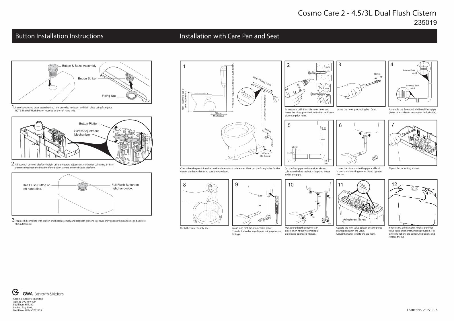
Button Installation Instructions
235019
Installation with Care Pan and Seat
2 38 mm
10 mm
3 mm
11
Actuate the inlet valve at least once to purgeany trapped air in the valve.Adjust the water level to the WL mark.
Adjustment Screw
Lea�et No. 235519~A
Caroma Industries Limited.ABN 35 000 189 499Baulkham Hills BCLocked Bag 5005,Baulkham Hills NSW 2153
Make sure that the strainer is inplace. Then �t the water supplypipe using approved �ttings.
Assemble the Extended Mid Level Flushpipe(Refer to installation instruction in �ushpipe).
Cut the �ushpipe to dimensions shown.Lubricate the kee seal with soap and waterand �t the pipe.
Lower the cistern onto the pipe and hook it over the mounting screws. Hand tighten the nut.
Nip up the mounting screws.
Flush the water supply line. Make sure that the strainer is in place. Then �t the water supply pipe using approved�ttings.
Check that the pan is installed within dimensional tolerances. Mark out the �xing holes for thecistern on the wall making sure they are level.
In masonry, drill 8mm diameter holes and insert the plugs provided. In timber, drill 3mmdiameter pilot holes.
Leave the holes protruding by 10mm.
If necessary, adjust water level as per inletvalve installation instructions provided. If all cistern functions are correct, �t buttons andreplace the lid.
External Seal Joint
Internal Seal Joint
20mm
53mm
6
8 9
5
4 1
10 12
7Screw Adjustment Mechanism
Button Platform
2. Adjust each button’s platform height using the screw adjustment mechanism, allowing 2 - 3mm clearance between the bottom of the button strikers and the button platform.
Half Flush Button on left hand-side.
Full Flush Button on right hand-side.
1. Insert button and bezel assembly into hole provided in cistern and �x in place using �xing nut. NOTE: The Half Flush Button must be on the left hand side.
Fixing Nut
Button & Bezel Assembly
Button Striker
100mm
285mm Fixing Holes
320mmMin Setout
mm052
seloH gnixiF xaM
mm0001
1100
max
. Req
uire
men
t to
top
of p
ush
butto
n.
320mmMin Setout
460
- 480
mm
to to
p of
se
at re
quire
men
t.
3. Replace lid complete with button and bezel assembly and test both buttons to ensure they engage the platforms and activate the outlet valve.