installation/operation manual - … 2010.pdf · installation/operation manual ... (dataline). when...
TRANSCRIPT

CP-2 Self-Contained System (For Free Exit and Home Automation)
INSTALLATION/OPERATION MANUAL
Preferred Technologies Group
Manufactured by:
(800) 878-7829 www.USAutomaticGateOpeners.com

Introduction .........................................................................3
Bench Testing and Field Testing.........................................3
Location of CP-2 .................................................................3
Installation of CP-2..............................................................4
Alternative Installations for Gate Operators ........................4
Directional Detection...........................................................5
Power Hook-Up ..................................................................5
Relay Hook-Up....................................................................5
Earth Ground ......................................................................5
Power Outages and Rebooting ...........................................5
Splicing Instructions ........................................... Back Cover
Warranty Information ......................................... Back Cover
Merchandise Return Information........................ Back Cover
Technical Specifications .................................... Back Cover
Copyright 2009 by Preferred Technologies Group
TABLE OF CONTENTS
This Table of Contents is clickable. Point and Click! This Table of Contents is clickable. Point and Click!
(800) 878-7829 www.USAutomaticGateOpeners.com

INTRODUCTION
The CP-2 system is an electronic vehicle detection device based on electromagnetic induction. It is designed to provide a trigger for Free-Exit and home automation. The sensor probe and all the control electronics are integrated within the same enclosure, with an attached cable, eliminating the need for an external control board. The installation is simplified with two wires for power, and two wires for the relay output. The MCU-based system achieves false-alarm-free operation by advanced “intellisense” technology held under a patent issued December 1998. BENCH TESTING AND FIELD TESTING
The system should be bench tested before installation, both by itself and in conjunction with the gate op-erator (or other equipment to which it will be connected). Make all measurements only with a digital multime-ter with 10 MEG ohm or more input resistance. An analog VOM will not work for this test.
With the power off, connect the negative side of the digital volt meter to the braided SHIELD wire and posi-tive side of the meter to the BLACK wire (DATALINE). When the CP-2 is powered, the meter should read less than .100 VDC for a period of about 2 seconds; then it should read between 4.5 VDC and 5.5 VDC for about 4 seconds. It should then return to 0 voltage. WARNING! DO NOT touch the leads of the digital multimeter with your fingers or the test will be invalidated.
After the power test proves successful, test the CP-2 by passing a steel object over the sensor to verify relay closure. Power it down. Before putting power to the CP-2 in the field, attach and solder the BLACK wire (DATALINE) permanently to the braided SHIELD in single probe applications.
LOCATION OF CP-2
See Figure 2 on page 4. When the CP-2 is used for “free-exit” for an automatic gate, locate the sensor probe at least 50 to 75 feet before the gate. The CP-2 can cover a 12 foot wide driveway (including width of car) from the dirt beside the driveway. For wider driveways (up to 24 feet), bury the CP-2 under the driveway in its center (see Figure 2). When two probes are used, one on each side of the driveway, together they will cover a 17 foot wide driveway.
The CP-2 may be placed parallel, perpendicular, horizontal or vertical to the driveway surface; however, its most sensitive position is parallel to the flow of traffic. The system can be buried below the ground or mounted above ground. When mounting above ground, the CP-2 must be horizontal to the ground and no
WARNING! The CP-2 is only a trigger. It cannot act as a safety nor does it include a safety. To use with a gate operator, an external safety must be added.
WARNING! A child on a bicycle, tricycle or other moving steel playing equipment; horses, ATV’s, golf carts, lawn mowers and other small vehicles may trip the CP-2 and cause the automatic gate to open. See “ALTERNATIVE INSTALLATIONS” on p. 2 for further information.
Figure 1 — Wire Diagram (see page 5)
Back to Table of Contents
3
Back to Table of Contents
Back to Table of Contents
CP-2 SELF-CONTAINED SYSTEM MANUAL
PRIOR TO JULY 2009, FOLLOW THIS DIAGRAM:
Back to Table of Contents
(800) 878-7829 www.USAutomaticGateOpeners.com

higher than two feet. Run the cable in non-magnetic conduit or PVC pipe for mechanical protection. Sta-tionary steel near the CP-2 will not affect its opera-tion. It may also be installed under the steel reinforc-ing grid of a concrete roadway without affecting its operation.
Install the CP-2: • At least 6-10 feet away from a buried power or
telephone line or invisible fence • At least 10 feet away from a natural gas line • At least 20 feet away from a power pole with a
transformer • At least 100 feet back from railroad traffic • At least 200 feet away from high power substation power lines • At least 50 feet back from traffic traveling over 35 MPH • At least 35 feet back from traffic traveling under 35 MPH
INSTALLATION OF CP-2
See Figure 2. Bury the CP-2 sensor probe 6-10 inches below the surface and beside the driveway. Bury an additional 10 feet of coiled-up wire with the probe for future relocation, etc. Bury cable 3 inches deep in cultured grass using a trencher or lawn edger (use an abrasive concrete saw in frozen ground). In field grass or uncultured grass, bury cable 6-10 inches deep. Be sure to push the wire to the bottom of the slice and tamp the sliced area. When running above ground, place the cable in conduit or PVC pipe for protection. If run overhead, attach to a steel cable with plastic ties every 6-10 feet. Connect to power as described on page 3, “Power Wire Hook Up.”
NOTE: The cable CAN be buried in the same trench as power and telephone lines, but not in the same conduit. Refer to local and national electrical codes.
When installing the CP-2 in concrete or pavement, bore a 2½ inch diameter hole VERTICALLY and 24 inches deep. Make a 1/4 inch wide slice in the pavement from the bored hole to the side of the driveway and patch over the cable. Connect to power as described on page 3, “Power Wire Hook Up.”
When installing the CP-2 in a dirt or gravel driveway, first bury a 2½ inch schedule 80 PVC pipe in the cen-ter of the driveway, 6-8 inches deep, and diagonally at a 45 degree angle (see Figure 2). Slide the CP-2 and cable in the pipe to the center of the driveway. This could be used in a driveway up to 24 feet wide. When installing in new construction, bury the 2 inch PVC pipe under the driveway as described above. Pour cement or asphalt the drive. Insert the CP-2 and cable after landscaping is complete to prevent possible damage to cable. Connect to power as described on page 3, “Power Wire Hook Up.”
NOTE: When pulling the cable through conduit or PVC pipe, it is important that every inch of cable be lib-erally lubricated and pull only 100 feet or less at one time. The cable is coated with polyurethane for splicing purposes and thereby makes for a cable with extremely high traction which causes a tremendous drag when not lubricated; enough to inconspicuously snap the wire inside the rubber casing.
WARNING! Extreme care must be taken with the CP-2 cable. To unroll it, put your arm through the center of the roll, remove the tape, and unravel the roll one wrap at a time. Unwrap the roll entirely before laying it down.
ALTERNATIVE INSTALLATIONS FOR GATE OPERATORS
If children on tricycles and horses with steel shoes trip the CP-2, simply bury the CP-2 probe two feet deep and parallel with the driveway. This reduces the possibility of small objects tripping the CP-2.
If you do not want smaller, slower vehicles (e.g. bicycles, golf carts, ATV’s, etc.) to trip the CP-2 and open a gate, then do the following: 1. Space two CP-2 probes ten linear feet apart. 2. Bury them one foot deep and parallel with the driveway. 3. Run the cable of each probe to the gate operator.
4
Figure 2
Back to Table of Contents
Back to Table of Contents
(800) 878-7829 www.USAutomaticGateOpeners.com

4. At the gate operator, connect BLACK wire (DATALINE) of each probe to its own braided SHIELD. 5. At the gate operator, connect the GREEN wire of one probe to the GREEN wire of the second probe.
Connect the BLUE wires (one from each probe) to the two free exit terminals on the operator board. If there is a single free exit terminal, connect the BLUE wire from one CP-2 to the FREE EXIT terminal, and the BLUE wire from the second CP-2 to the NEGATIVE VOLTAGE or SYSTEM COMMON or GROUND.
6. Power both probes from the same source (DC or AC). When this two-probe system is used, both probes need to be activated within a short period of time to trip
the system (e.g. a car traveling at least 5 MPH). Smaller and slower vehicles will usually not trip the system. If there are other questions concerning applications, call Preferred at 800-223-4743.
DIRECTIONAL DETECTION
When at least two CP-2 units are placed 10 to 20 feet apart (see chart below), bi-directional capability is possible. To achieve this, simply solder the BLACK wire (DATALINE) from one CP-2 to the BLACK wire (DATALINE) of the second CP-2. This guarantees a response only from the CP-2 tripped first. For home automation, the directional system can turn on lights, cameras and annunciation when entering the property, and offer another or no response when the vehicle leaves. Note: In directional applications use only clean DC power. DO NOT use AC power when directional. To achieve directional capability, four conditions must exist: 1. Two CP-2 systems are used 2. A DC power source is used 3. The BLACK wire (DATALINE) of one CP-2 is connected, soldered and taped to the BLACK wire of the
second CP-2 4. The CP-2’s are all powered from the same power source, and powered up together
POWER HOOK UP
See Figure 1 on page 3. For single CP-2 and alternative installation applications, solder the BLACK wire (DATALINE) permanently to the braided or bare SHIELD wire.
For DC voltages, connect the RED wire to the positive side of the power supply. Connect the SHIELD and BLACK wire combination to the negative side of the power supply. For AC voltages, connect the AC power between the RED wire and the SHIELD and BLACK wire combination.
WARNING! The BLACK wire is not a power wire. Internal damage will occur if power is applied to the BLACK (DATALINE) wire. The BLACK wire must be connected to the braided or bare SHIELD wire before power is applied. It can be used for testing and for directional applications (see above).
RELAY HOOK-UP
See Figure 1 on page 3. The BLUE and GREEN wires provide the relay output (normally open). Connect the BLUE and GREEN wires to the two FREE EXIT terminals on the gate operator board (if so equipped). If there is a single FREE EXIT terminal, connect the BLUE wire to the FREE EXIT terminal and the GREEN wire to the NEGATIVE VOLTAGE or SYSTEM COMMON or GROUND terminal (refer to your gate operator manual). In a home automation system, connect the BLUE and GREEN wires to the ZONE INPUT.
EARTH GROUND
The CP-2 has been designed to operate with or without an earth ground.
POWER OUTAGES AND REBOOTING
The relay used in the CP-2 system is a magnetic latching relay. Under normal circumstances, the relay will be open when you receive it. However, if the CP-2 is jarred in shipping the relay may close and remain that way until power is applied to the CP-2. If the CP-2’s relay is closed and it is attached to a gate operator before it is powered up, the CP-2 may open the gate (and cause it to remain open). If this occurs, simply ap-ply power to the CP-2. The relay will open again and operate properly.
5
From 0 - 40 MPH driveway speed Place CP-2’s 10 feet apart
Over 40 MPH driveway speed Place CP-2’s 20 feet apart
CHART SHOWING DISTANCE BETWEEN DIRECTIONAL SENSORS VS MPH
Back to Table of Contents
Back to Table of Contents
Back to Table of Contents
Back to Table of Contents
Back to Table of Contents
(800) 878-7829 www.USAutomaticGateOpeners.com
On rare occasions, when a momentary power outage occurs, the CP-2 may stop working. If this occurs, it must be rebooted. To reboot the CP-2, simply disconnect one of the power leads. After a minute or more, reconnect the lead to power. This will restore the CP-2 to normal operation mode.
SPLICING INSTRUCTIONS
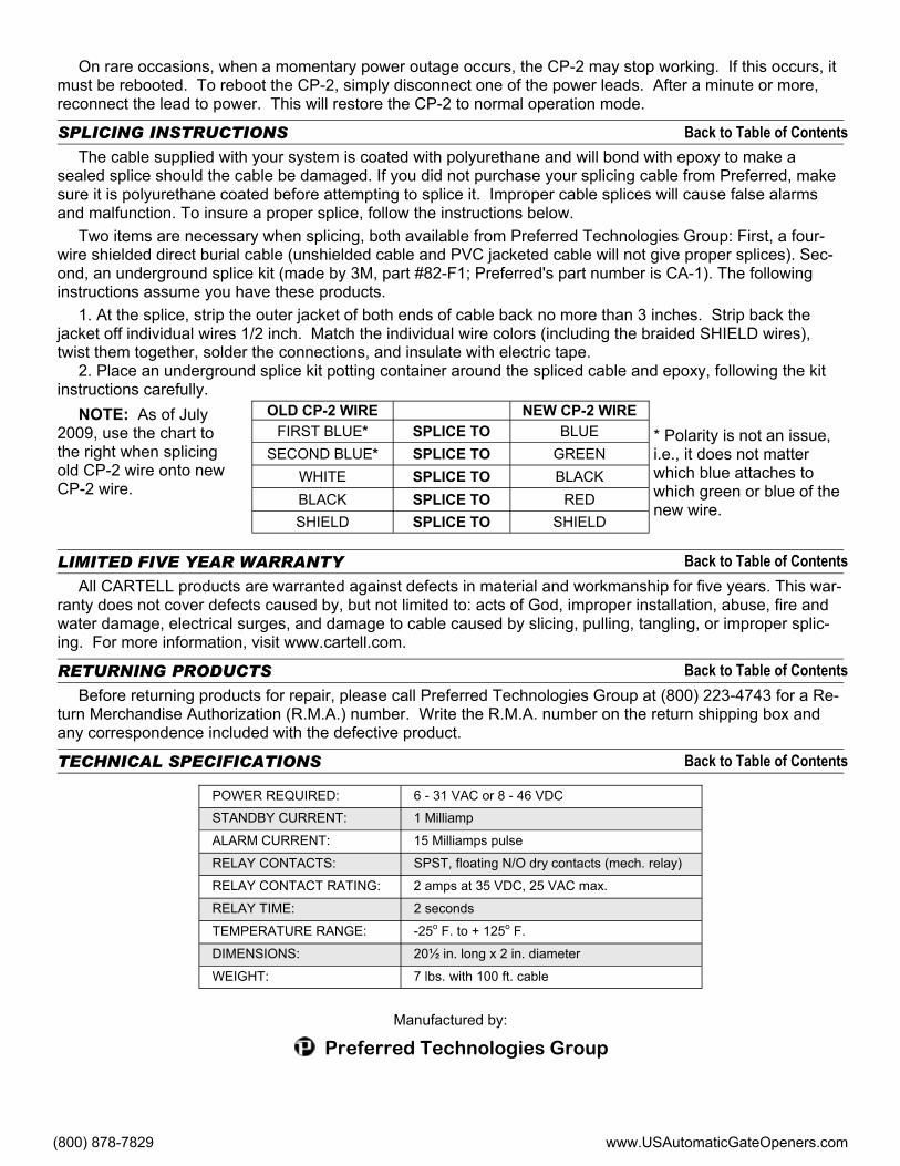
The cable supplied with your system is coated with polyurethane and will bond with epoxy to make a sealed splice should the cable be damaged. If you did not purchase your splicing cable from Preferred, make sure it is polyurethane coated before attempting to splice it. Improper cable splices will cause false alarms and malfunction. To insure a proper splice, follow the instructions below.
Two items are necessary when splicing, both available from Preferred Technologies Group: First, a four-wire shielded direct burial cable (unshielded cable and PVC jacketed cable will not give proper splices). Sec-ond, an underground splice kit (made by 3M, part #82-F1; Preferred's part number is CA-1). The following instructions assume you have these products.
1. At the splice, strip the outer jacket of both ends of cable back no more than 3 inches. Strip back the jacket off individual wires 1/2 inch. Match the individual wire colors (including the braided SHIELD wires), twist them together, solder the connections, and insulate with electric tape.
2. Place an underground splice kit potting container around the spliced cable and epoxy, following the kit instructions carefully.
* Polarity is not an issue, i.e., it does not matter which blue attaches to which green or blue of the new wire.
LIMITED FIVE YEAR WARRANTY
All CARTELL products are warranted against defects in material and workmanship for five years. This war-ranty does not cover defects caused by, but not limited to: acts of God, improper installation, abuse, fire and water damage, electrical surges, and damage to cable caused by slicing, pulling, tangling, or improper splic-ing. For more information, visit www.cartell.com.
RETURNING PRODUCTS
Before returning products for repair, please call Preferred Technologies Group at (800) 223-4743 for a Re-turn Merchandise Authorization (R.M.A.) number. Write the R.M.A. number on the return shipping box and any correspondence included with the defective product.
TECHNICAL SPECIFICATIONS
POWER REQUIRED: 6 - 31 VAC or 8 - 46 VDC
STANDBY CURRENT: 1 Milliamp
ALARM CURRENT: 15 Milliamps pulse
RELAY CONTACTS: SPST, floating N/O dry contacts (mech. relay)
RELAY TIME: 2 seconds
TEMPERATURE RANGE: -25o F. to + 125o F.
RELAY CONTACT RATING: 2 amps at 35 VDC, 25 VAC max.
DIMENSIONS: 20½ in. long x 2 in. diameter
WEIGHT: 7 lbs. with 100 ft. cable
OLD CP-2 WIRE FIRST BLUE* SPLICE TO
SECOND BLUE* SPLICE TO WHITE SPLICE TO BLACK SPLICE TO SHIELD SPLICE TO
NEW CP-2 WIRE BLUE
GREEN BLACK
RED SHIELD
NOTE: As of July 2009, use the chart to the right when splicing old CP-2 wire onto new CP-2 wire.
Back to Table of Contents
Back to Table of Contents
Back to Table of Contents
Back to Table of Contents
Preferred Technologies Group
Manufactured by:
(800) 878-7829 www.USAutomaticGateOpeners.com