installation/user guide operation & maintenance manual revb.pdf · maintenance ... jun-air...
TRANSCRIPT

Part No. CI-100A (Rev B)
Dental Vacuum Suction SystemInstallation/User GuideOperation & Maintenance Manual
® Registered Trademark/™ Trademark of JUN-AIR Inc. ©Copyright 2012 JUN-AIR Manufacturing Inc. All Rights Reserved.
WWW.JUN-AIR.COM
ISO 9001 CERTIFIED
2
CI-100A (Rev B) JUN-AIR Dental Vacuum Suction System User Guide
© 2012, JUN-AIRWe reserve the right to make any alterations which may be due to any technical improvements
Printed in the USA
TABLE OF CONTENTS
Important Safety Instructions and Regulatory Information . . . . . . . . . . . . . . . . . . . . . . . . . . . 2-4System features . . . . . . . . . . . . . . . . . . . . . . . . . . . . . . . . . . . . . . . . . . . . . . . . . . . . . . . . . . . . . .5Unpacking . . . . . . . . . . . . . . . . . . . . . . . . . . . . . . . . . . . . . . . . . . . . . . . . . . . . . . . . . . . . . . . . . .7 Installation Safety Data . . . . . . . . . . . . . . . . . . . . . . . . . . . . . . . . . . . . . . . . . . . . . . . . . . . . . . . . . . . . . .8 Site Requirements . . . . . . . . . . . . . . . . . . . . . . . . . . . . . . . . . . . . . . . . . . . . . . . . . . . . . . .10 Plumbing . . . . . . . . . . . . . . . . . . . . . . . . . . . . . . . . . . . . . . . . . . . . . . . . . . . . . . . . . . . . . .11 Installation - Below Grade . . . . . . . . . . . . . . . . . . . . . . . . . . . . . . . . . . . . . . . . . . . . . . . . .13 Installation - Above Grade . . . . . . . . . . . . . . . . . . . . . . . . . . . . . . . . . . . . . . . . . . . . . . . . .14 Electrical . . . . . . . . . . . . . . . . . . . . . . . . . . . . . . . . . . . . . . . . . . . . . . . . . . . . . . . . . . . . . . .15 Checks and tests . . . . . . . . . . . . . . . . . . . . . . . . . . . . . . . . . . . . . . . . . . . . . . . . . . . . . . . .16Operation . . . . . . . . . . . . . . . . . . . . . . . . . . . . . . . . . . . . . . . . . . . . . . . . . . . . . . . . . . . . . . . . . .17Maintenance . . . . . . . . . . . . . . . . . . . . . . . . . . . . . . . . . . . . . . . . . . . . . . . . . . . . . . . . . . . . . . .18Specifications . . . . . . . . . . . . . . . . . . . . . . . . . . . . . . . . . . . . . . . . . . . . . . . . . . . . . . . . . . . . . .19Troubleshooting Chart . . . . . . . . . . . . . . . . . . . . . . . . . . . . . . . . . . . . . . . . . . . . . . . . . . . . . 20-22 Options & Accessories . . . . . . . . . . . . . . . . . . . . . . . . . . . . . . . . . . . . . . . . . . . . . . . . . . . . . . .23 Warranty . . . . . . . . . . . . . . . . . . . . . . . . . . . . . . . . . . . . . . . . . . . . . . . . . . . . . . . . . . . . . . . . . .23Installation Checklist . . . . . . . . . . . . . . . . . . . . . . . . . . . . . . . . . . . . . . . . . . . . . . . . . . . . . . . . .24
WARNING
PLEASE READ THIS MANUAL COMPLETELY BEFORE INSTALLING AND USING
THIS PRODUCT. SAVE THIS MANUAL FOR FUTURE REFERENCE AND
KEEP IN THE VICINITY OF THE PRODUCT.
Dear Customer:
Congratulations on the purchase of your new JUN-AIR Dental Vacuum Suction System .
This system’s intended purpose is for dental suction applications . It is to be used in accor-dance with UL60601-1 and NFPA 99C stan-dards, along with all applicable codes . The sys-tem utilizes a dry vacuum regenerative blower that produces high air flow when connected to the dental operatory lines .
IMPORTANT SAFETY INSTRUCTIONS
A vacuum relief valve is also included to maxi-mize the system’s efficiency by holding a con-stant vacuum level . This manual provides instal-lation, operation and preventative maintenance guidelines that should be followed to ensure correct/reliable performance of this system .

3© 2012, JUN-AIRWe reserve the right to make any alterations which may be due to any technical improvementsPrinted in the USA
JUN-AIR Dental Vacuum Suction System User Guide CI-100A (Rev B)
TABLE OF SYMBOLS
CAUTION: Indicates a potentially hazardoussituation which may result in minor ormoderate injury if not avoided. It may also beused to alert against unsafe practices.
WARNING: To Avoid Serious Burns:Do not touch surface during operation.
Indicates the ON and OFF position for the Equipment power Switch
ON OFF
IO
Indicates package should be handled with these symbols pointing up.
FRAGILE: Handle package with care.
Indicates this package must be kept dry.
Indicates the acceptable shipping temperature range.
-29 °C-20 °F
+50 °C+122 °F
Indicates the acceptable maximum relative humidity for shipping.
95
Indicates the acceptable lowest barometricpressure conditions in which this unit canbe shipped.372MM HG
.49 ATM

4
CI-100A (Rev B) JUN-AIR Dental Vacuum Suction System User Guide
© 2012, JUN-AIRWe reserve the right to make any alterations which may be due to any technical improvements
Printed in the USA
INTENDED USE:To provide suction during general dental examina-tions and procedures conducted by qualified dental professionals.
JUN-AIR vacuum systems meet or exceed the most current and highest safety standards, which are:
• CSA C22.2 601.1-M90 (2005)
• UL60601-1 classified revision 2006/04/26
- Classification: Class I, permanently fixed MAINS operated equipment
• NFPA 99C level 3 gas system requirements compliance revision 2005
• NFPA 70 (National Electric Code) revision 2008
• ISO 9001:2008
• Ingress protection: IPX0
To ensure the safety potential of this equip-ment is achieved, please:Make sure your equipment is installed according to the instructions provided in this manual and make sure the installation checklist is completed prior to starting the equipment.
Equipment is not suitable for use in the presence of a flammable anesthetic mixture containing air/oxygen or nitrous oxide. DO NOT OPERATE THE EQUIP-MENT IF THESE CONDITIONS EXIST.
Protection against electrical shock:Provide proper grounding per NFPA 70 (NEC 2008). Do not become a current path for the equipment to ground through your body.
Transportation/Storage Conditions:• Temperature range -28.5 °C to 50 °C / -20 °F to
122 °F
• Relative Humidity 95% (non-condensing)
• Barometric pressure minimum of 372 mm Hg (.49 atm)
Do not stack units during shipment/storage or installation.
Important: Refer servicing to an authorized service representative.
REGULATORY INFORMATION

5© 2012, JUN-AIRWe reserve the right to make any alterations which may be due to any technical improvementsPrinted in the USA
JUN-AIR Dental Vacuum Suction System User Guide CI-100A (Rev B)
SYSTEM FEATURES
Inlet From OperatorySystem Check Valve
(3) Lid Knobs
Vacuum Relief Valve(Any required adjustments are onlyto be made by an authorized distributor. Improper adjusment will cause overheatingand failure.)
Drainage Elbow/Check Valve
Drain
2 X Cabinet Fans
Exhaust From Blower

6
CI-100A (Rev B) JUN-AIR Dental Vacuum Suction System User Guide
© 2012, JUN-AIRWe reserve the right to make any alterations which may be due to any technical improvements
Printed in the USA
SYSTEM FEATURES
Separation Tank
Tank Support Frame
Sound Enclosure
Electrical Panel Cover
Hour Meter
4 X Leveling Feet
System Breaker
Power On Indicator Light
Low Pressure Hose
Vacuum Gauge

7© 2012, JUN-AIRWe reserve the right to make any alterations which may be due to any technical improvementsPrinted in the USA
JUN-AIR Dental Vacuum Suction System User Guide CI-100A (Rev B)
UNPACKING
1. Examine contents for damage prior to removing shipping carton.
a. If shipping damage is found, immediately contact the freight carrier to file a claim.
2. Carefully remove the shipping carton from the pallet containing the vacuum system.
3. Visually inspect the entire vacuum system for shipping damage.
a. If shipping damage is found, immediately contact the freight carrier and supplier.
4. Verify that the installation kit parts were shipped with the system:
a. Installation kit parts shipped with all vacuum system models include the following:
• (3) Hose barbs
• (6) Hose clamps
• (3) Low pressure intake hoses (37.5 inches in length)
• (1) O&M Manual
5. Remove the installation kit parts and set aside until the unit is ready to be installed.
6. Remove the (8) 5/16 in carriage bolts and the four shipping brackets from the sound enclosure.
7. Remove the (3) 5/16 in carriage bolts from the tank support frame.
8. Remove the band strap from tank.
Protective foam
3 x 5/16 incarriage bolts
8 x 5/16 incarriage bolts
4 x shippingbrackets
37.5"
Hose Clamp Hose Barb Hose
WARNING: DO NOT install on surfaces with more than a 5° incline.
WARNING: Fasten unit to shipping pallet prior to transporting the equipment to prevent tipping or drainage.

8
CI-100A (Rev B) JUN-AIR Dental Vacuum Suction System User Guide
© 2012, JUN-AIRWe reserve the right to make any alterations which may be due to any technical improvements
Printed in the USA
PERSONAL SAFETY:
DANGER: Danger of fire or explosion when using flammable substances. Do not operate the vacuum system in an area containing combustible gases or anesthetic mixtures.
CAUTION: Do not place vacuum system within 6 feet of patient.
CAUTION: Never leave children unattended near vacuum system when in use.
WARNING: Property damage and/or personal injury may result if directions are not followed or manufacturer’s replacement parts/accessories are not used.
WARNING: Connect only equipment suitable for listed maximum vacuum level of the blower. Equipment is not suitable for use in vital (continuation of life) operations, an alternative air source should be used in these instances.
WARNING: A leaking vacuum relief valve may indicate a need for adjustment or repair. Any required adjustments are only to be made by an authorized distributor. Improper adjustment will cause overheating and failure.
PLACEMENT:• Indoor use only in dust free, climate controlled
room.
• DO NOT install in an enclosed area where ambient temperature could exceed temperature specifications of below 4.5 °C / 40 °F, or above 40 °C / 104 °F while the vacuum system is run-ning.
• Maintain minimum 6 inches of clearance around system. Maintain 12 inches of clearance on top of system.
• Vacuum systems are equipped with 4 adjust-able feet, to ensure unit stands firmly on the floor. Level the system in two plains prior to starting system.
• Assure proper external exhaust ventilation prior to starting the system (see SPECIFICATIONS).
INSTALLATION SAFETY DATA
Indicates the ON and OFF position for the equipment power switch (system breaker)
When ON, the indicator light will illuminate and voltage WILL be supplied to system.
When OFF, the indicator light will NOT illuminate and voltage WILL NOT be supplied to the system.
I
o= ON
= OFF
I o
Equipment Alert: Vacuum system must be installed per local plumbing and electrical codes.

9© 2012, JUN-AIRWe reserve the right to make any alterations which may be due to any technical improvementsPrinted in the USA
JUN-AIR Dental Vacuum Suction System User Guide CI-100A (Rev B)
CAUTION: Routinely inspect any and all power cords for cuts and abrasions. Discontinue use and have authorized service representative replace cord if damaged.
ELECTRICAL SAFETY:
• Follow NEC, NFPA 99C and all applicable local codes.
• Systems are shipped with appropriate electrical conduit to hardwire into stand alone breaker.
• Qualified personnel must install electrical wiring and outlets.
• Unit requires a dedicated (separate branch circuit only) 30 amp circuit, 230 VAC.
• Never operate unit outside the specified voltage range 208-253 VAC. (see page 15, “INSTALLATION - ELECTRICAL”)
• See “SPECIFICATIONS” for more electrical information.
• There is an indicator light on the system which indicates the power is on.
ELECTROMAGNETIC INTERFERENCE (EMI):The JUN-AIR vacuum suction system is designed to avoid electromagnetic emissions/interference with surrounding electrical equipment. Due to the vast assortment of electrical equipment available, it is possible that some interference may be experienced by the end customer. If interference is experienced, the device that is creating interference should be removed from the room where the vacuum system is located. If the interference persists, then it may be necessary to confirm that both devices are connected to isolated (separated) circuits per “ELECTRICAL INSTALLATION INSTRUCTIONS” in this manual. If the problem still occurs, then the two devices should be moved as far apart as possible. Finally, if the problem can not be eliminated, contact an authorized distributor.
INSTALLATION SAFETY DATA
�Install this product
Install this product where it will be weatherprotected.
Failure to follow these instructions can result indeath, fire or electrical shock.
Electrical Shock Hazard
WARNING
This product must be properly grounded. Electrically ground this product per local codes.
Follow all local applied codes prior to installation.
Do not permanently connect this product to wiring that is not in good condition or is inadequate forthe requirements of this product.
Check the condition of the power supply wiring.
The wire with insulation that is green or greenwith yellow stripes is the grounding wire.
in a dry location.
Disconnect electrical power at the circuit breakeror fuse box before installing this product.
WARNING: Use of an extension cord is not advisable. An undersized extension cord will cause a drop in line voltage and loss of power. Overheating and fire may result.
WARNING: Electric shock could
occur as a result of improper grounding. This product must be grounded according to NEC regulations and all local codes.
WARNING: Always turn off vacuum system and remove power from unit when servicing or removing electrical cover. Lock out power at breaker(s) prior to servicing.

10
CI-100A (Rev B) JUN-AIR Dental Vacuum Suction System User Guide
© 2012, JUN-AIRWe reserve the right to make any alterations which may be due to any technical improvements
Printed in the USA
INSTALLATION - SITE REQUIREMENTS
Dental Site Requirements JVac3 JVac5 JVac7ElectricalWire gauge (AWG) #10 #10 #10
Minimum circuit breaker current rating 30 A 30 A 30 APlumbingExhaust vent pipe to outside 1.5 inch NPT (must be metal)Line from operatory See applicable plumbing diagramInlet hose barb on vacuum separator tank 1.5 inches 1.5 inches 1.5 inchesSeparator tank drain hose 1.5 inches 1.5 inches 1.5 inchesNote: if alternate site pipe sizes are to be used, consult an authorized distributor
Minimum 12" spacingbetween system & ceiling
(recommended 18" for servicability)
1-1/2" NPTsystem drain
NOTE: All dimensions are in inches
Minimum 6" spacingbetween system & any walls
Inlet from operatoryfor 1-1/2" I.D. tube
1-1/2" NPTsystem exhaust
Ø 15.25
0.7
63.4
32.5
61.9
21.2924.1
6 in min.
13.4
26.0
12 inches min.; 18 inches recommended

11© 2012, JUN-AIRWe reserve the right to make any alterations which may be due to any technical improvementsPrinted in the USA
JUN-AIR Dental Vacuum Suction System User Guide CI-100A (Rev B)
INSTALLATION - PLUMBING
WARNING: The system should only be installed by qualified personnel. The system should be installed in a clean, dry, well ventilated area on a solid, level surface.
1. Unpack system from carton, removing any wooden pallets (only used for shipping integrity).
2. Set the unit in place and be certain it is level and cannot rock (adjust leveling feet accordingly).
3. Remove the 3 x acorn nuts from the system’s drip plate.
4. Set the tank and tank support frame on the drip plate and align the 3 x thru holes of the support frame to the 3 x threaded studs sticking through the drip plate.
5. Attach the support frame/tank to the sound enclosure by tightening the 3 x acorn nuts (previously removed) to the threaded studs.
6. Position the tank lid as shown in the installation schematic above, connect the tank lid assembly to the blower intake with a hose and two hose clamps as shown above.
7. Locate exhaust pipe protruding from sound cover and position accordingly to face customer’s exhaust air vent. Exhaust vent connections should be made with a 1-1/2” NPT steel or copper pipe to the outside of the building.
WARNING: The exhaust plumbing must be connected to a vent which runs outside of the building per NFPA 99C Standards. The outside vent should be turned down and screened to protect from rain and animals.
To drain
Tank lidassembly connection point
Blower intakeconnection point
1-1/2" NPT
Drip plate
1-1/2" NPT To hosebarb adapter
1-1/2" ID low pressure hose
3 X acornnuts
1-1/2" NPT To steelexhaust pipe
1-1/2" NPTconnected to operatory
Lid knobs
Drainage elbow/check valve
For new installations, it is recom-mended to use the following guide-lines.

12
CI-100A (Rev B) JUN-AIR Dental Vacuum Suction System User Guide
© 2012, JUN-AIRWe reserve the right to make any alterations which may be due to any technical improvements
Printed in the USA
INSTALLATION - PLUMBING
8. Position the tank’s operatory inlet and drainage elbow/check valve accordingly by rotating the tank in its frame. It may be necessary to lift the tank from the frame and adjust the drainage elbow to align with waste disposal line and maintain alignment with the operatory inlet.
NOTE: Tank lid must remain clocked in its factory set location. If the tank needs to be rotated, the lid must first be loosened by turning the (3) lid knobs counter clockwise until lid is loose.
NOTE: After the tank and drainage elbow are properly positioned, the lid knobs should be tightened in a position which allows the plastic tubing, connecting the tank to the vacuum unit, to remain in a vertical position.
9. Check to make sure that the drainage elbow is tight in the tank. Connect 1-1/2” NPT female end of the drainage tube to the existing sewer drain line or floor sink. If existing line is not available, use 1-1/2” NPT plastic hose barb to connect low pressure hose to floor drain. The system must be installed so that the tank drain is higher than the waste connection. This will allow the tank to gravity drain. Use a hose clamp to secure the hose to the barb.
WARNING: See local codes in reference to Amalgam disposal.
10. Connect low pressure hose to operatory inlet on tank via a hose clamp. Assemble opposite end of hose to operatory plumbing with the remaining hose clamp.
WARNING: Hose from the operatory inlet must be installed so that it exceeds the height of the tank lid.
WARNING: Exhaust air plumbing must be supported within 2 feet of the enclosure (see illustration in STEP 2 of the INSTALLATION-TESTS AND CHECKS section).

13© 2012, JUN-AIRWe reserve the right to make any alterations which may be due to any technical improvementsPrinted in the USA
JUN-AIR Dental Vacuum Suction System User Guide CI-100A (Rev B)
INSTALLATION - BELOW GRADE PLUMBING
Installation Guidelines
• Where possible, use 1.5 inch to 2 inch ID plumbing to connect operatory lines to separation tank.
• Plumbing lines should be sloped down to the separation tank as shown in the schematic (minimum slope of 1/32 inch per foot).
• Low spots in the line should be avoided to prevent flow restriction of vacuum loss.
the separation tank
Minimum 1.5" ID Pipe
Risers to Operatory
Risers to Operatory
Slope pipe down towards
Ground Level
Connection must be higher than tank inlet

14
CI-100A (Rev B) JUN-AIR Dental Vacuum Suction System User Guide
© 2012, JUN-AIRWe reserve the right to make any alterations which may be due to any technical improvements
Printed in the USA
INSTALLATION - ABOVE GRADE PLUMBING
Installation Guidelines
• Use 1.5 inch to 2.0 inch ID plumbing to connect operatory lines to separation tank.
• Plumbing lines should be sloped down to the separation tank as shown in the schematic (minimum slope of 1/32 inch per foot).
• A maximum of a 10-foot rise is recommended for above-grade plumbing. If more than 10 feet of rise is required, contact your distributor.
• Low spots in the line should be avoided to prevent flow restriction or vacuum loss.
• It may be necessary to upgrade to the next largest system for an operatory with above-grade plumbing.
• All plumbing entering the main trunk line needs to be dropped in on the top of the trunk line as shown in the schematic.
the separation tank
Minimum 1.5" ID Pipe
Lines to Operatory
Slope pipe down towards
Ground Level
Max 10 Feet Height
Connection must be higher than tank inlet

15© 2012, JUN-AIRWe reserve the right to make any alterations which may be due to any technical improvementsPrinted in the USA
JUN-AIR Dental Vacuum Suction System User Guide CI-100A (Rev B)
INSTALLATION - ELECTRICAL CONNECTIONS
Refer to the ‘Specification’ sheet in this manual for Electrical Ratings.
1. Connect remote panel wires to Low Voltage Control wires if applicable. If a remote panel is not used, connect the red and white remote switch wires and insulate the black wire.
2. Connect conduit cable to user supplied electrical box.
3. Install a dedicated 30 AMP (see electrical schematic) circuit protection breaker.
NOTE: If fuse replacement is required, then a 250 mA/0.320 ohm rated resistance time-delayed, 200% overload rated fuse should be used. This fuse can be purchased through Bussman (Cooper), part number MDL-1/4-R or contact your distributor for replacement parts.
WARNING: Line voltage must be within the specified voltage range 208-253 VAC. The 30 AMP breaker must be de-lay/slow blow type. The breaker must have a trip time of greater than 2 sec-onds @ 400% overload.
WARNING: Connect in accordance with NEC Class 2 wiring methods and all applicable local codes.
* It is typical for industrial-type installations (secondary or primary y-type transformers) to have single phase power supplied from two legs of a three-phase power source. In these instances, large voltage drops and/or low initial voltage is quite common (208 VAC or less). If the initial line voltage is close to 208 VAC, then it is highly likely that the system’s running voltage will fall below the minimum requirements. JUN-AIR strongly recommends the use of a Buck/Boost transformer (EK587 - See ‘OPTIONS-ACCESSORIES’) to maintain an adequate running voltage for these types of scenarios, especially when installing a JVAC7 system.

16
CI-100A (Rev B) JUN-AIR Dental Vacuum Suction System User Guide
© 2012, JUN-AIRWe reserve the right to make any alterations which may be due to any technical improvements
Printed in the USA
INSTALLATION - CHECKS AND TESTS
1. Check that all the hose clamps (6) and hoses are securely fastened to the corresponding plumbing.
2. Check that the exhaust plumbing is tight and supported within 2 feet of the sound enclosure exit point.
3. Check the incoming line voltage. It should be a minimum of 208* volts and should not exceed 253 volts. The voltage should remain within this range while the system is running. If the voltage does not remain within the specified range, install an appropriate buck-boost transformer and check to make sure the correct main circuit breaker and wire size gauge are being used.
4. Turn power on at system breaker.
5. Close all operatory lines and check the maximum vacuum level reading on the vacuum gauge. (Reference ‘Specifications - Pneumatic’).
CAUTION: If the gauge does not read the respective vacuum limiter pre-setvalue, contact an authorized distributor (see ‘Specifications’ Section).
6. Use soapy water to check for leaks around external plumbing (i.e. hose clamps, pipe fittings, etc.) Make sure all fittings/hoses/PVC pipes are tightly secured.
7. Vacuum 2-4 gallons of fresh water into the system through the operatory line.
8. Turn the system off and check the drainage line from the tank to assure there are no leaks.
9. Check that the hose connected to the inlet of the tank is connected to the operatory plumbing at an elevation higher than the tank lid.
1
6
3
2
4
5
2 feetmax
Drainage Line
Equipment Alert: Vacuum system must be installed per local plumbing and electrical codes.
Equipment Alert: Verify all leaks are sealed. Air leaks are the main cause of inadequate system performance.
* See page 15 ‘INSTALLATION - ELECTRICAL’.

17© 2012, JUN-AIRWe reserve the right to make any alterations which may be due to any technical improvementsPrinted in the USA
JUN-AIR Dental Vacuum Suction System User Guide CI-100A (Rev B)
OPERATION
STEP 1A. The system may be turned on via the system
breaker located on the electrical cover at the base of the sound cover. A light above the system breaker will turn on to indicate that voltage is supplied to the system.
B. The system may also be turned “ON/OFF” from a single, convenient location within the dental office using a Remote Control Panel (if applicable). Remote wiring must be done by a licensed electrician in accordance with all applicable codes.
STEP 2 The vacuum level is factory preset per the
respective system limit (see ‘Specifications’). This is the reading on the gauge when all operatory lines are CLOSED. Check the gauge reading to the specified pre-set level per the pneumatic specifications in this manual. If the setting is within + .25 in. Hg. / -.75 in. Hg. of the specified rating for your system, continue with normal operation. If this setting needs to be adjusted, contact an authorized distributor.
STEP 3 Once the power is on and the vacuum preset
level has been checked, the system is fully operational.
NOTE: The vacuum systems are capable of running continuously. The system should be powered down when not in use to conserve electricity.
NOTE: The separation tank has a working volume, capable of collecting waste fluids for a standard operating day (8 hours). If excessive waste is collected, the tank has a ball float that will stop the vacuum flow and allow automatic drainage. Once the tank is completely drained, the system should be powered down for a minimum of 30 seconds. This will allow the ball float to return to its normal operating position, at which point the system can be turned back on.
STEP 4 At the end of the day, the system should be
powered down either at the remote panel or the system breaker (one or both of the controls should be moved to the “OFF” position). All waste collected will then automatically drain. One HVE should be left open overnight for adequate system ventilation to assure the tank will completely drain.
Hour Meter
Indicator Light
Breaker
Electrical Panel

18
CI-100A (Rev B) JUN-AIR Dental Vacuum Suction System User Guide
© 2012, JUN-AIRWe reserve the right to make any alterations which may be due to any technical improvements
Printed in the USA
MAINTENANCE
System Cleaning• The dental vacuum system should be thoroughly
cleaned at a minimum of 20 hour intervals. This will help to keep the system sterilized and functioning properly.
• To clean the system, flush non-foaming cleaning solvent through all main lines, into the tank and out of the drain. Follow the solvent manufacturer’s instructions.
• All hoses and liquid connections should be inspected at this time to ensure no leakage is occurring.
• The entire vacuum system (all operatory lines) should be flushed on weekly intervals.
Vacuum Relief Valve• Check the vacuum gauge level at one
month intervals to assure the system limit is appropriate. To do this, close off all operatory lines and power up the system. Reference the vacuum gauge located on top of the system lid to check the maximum vacuum level for the system. If the gauge varies by more than the amount specified in the ‘OPERATION’ section of this guide for the factory preset value (see ‘SPECIFICATIONS - PNEUMATIC’), contact your authorized distributor for adjustment.
• The valve should be cleaned at one month intervals to remove any clogs which can degrade the system’s performance. To do this, blow out any solid deposits (using clean, low pressure air) that may be caught in the relief valve. Use compressed air and a nozzle to blow air over all surfaces of the valve for a minimum of 30 seconds.
WARNING: Do not exceed the OSHA requirements of 30 psig air for cleaning purposes.
WARNING: Disposal of system or components (once deemed non-usable by the authorized distributor and end user) should be done in accordance with all local codes. Contact your local waste management authorities to determine proper disposal methods.
General Maintenance• During any service technician visit, routine
checks should be made for general wear/degradation of components. Any recommendations for replacement parts should be followed to keep the vacuum system running in optimal condition.
• All operatory/vacuum lines should be cleaned with a non-foaming solvent prior to installation. Follow the solvent manufacturer’s instructions.
• Separation tanks should be cleaned to remove solids at least once a year. The tank lid should be removed and the tank should be flushed with water until any solid buildup has been removed from the tank and flushed down the drainage line. This should be done with the appropriate protective clothing.
WARNING: Latex gloves, long sleeve shirt and face mask should be worn. If your skin or eyes come in contact with any tank liquids/solids contact your local BIOHAZARD authority immediately.
• The sound enclosure cabinet fans should be checked monthly (and cleaned when dirty) to assure proper air flow over the vacuum pump. To do this, energize the system and visually check to make sure both fans are on and rotating. If the fans are not rotating, immediately contact your authorized distributor and turn the system off to prevent overheating. The fans are located on the back side of the system and can be viewed through the slots on the sound enclosure.

19© 2012, JUN-AIRWe reserve the right to make any alterations which may be due to any technical improvementsPrinted in the USA
JUN-AIR Dental Vacuum Suction System User Guide CI-100A (Rev B)
Specifications JVac3 JVac5 JVac7ElectricalVoltage 230 230 230*Frequency (Hz) 60 60 60Phase Single Single SingleOperating current (amps) 6.3 A 12.5 A 12.5 AStarting current (amps) 50 A 70 A 70 AHorsepower 1.5 3.0 3.0Insulation class F F FPneumaticMax. vacuum (in Hg) 8.5 10 12Vacuum limiter preset (in Hg) 7.25 9 10Open vacuum air flow (CFM) 60 80 100Separation tank capacity (working fluid)
8 gallons 8 gallons 8 gallons
Tank material stainless steel stainless steel stainless steelAmbient SpecificationsOperating temperature 4.5 °C to 40 °C [40 °F to 104 °F]Relative humidity (non-condensing)
0 to 90 % 0 to 90 % 0 to 90 %
Environment clean and dust free clean and dust free clean and dust freeDimensionsHeight (in) 64 64 64Diameter (in) 26 26 26Weight (lb) 190 225 225
* See page 15 ‘INSTALLATION - ELECTRICAL’.

20
CI-100A (Rev B) JUN-AIR Dental Vacuum Suction System User Guide
© 2012, JUN-AIRWe reserve the right to make any alterations which may be due to any technical improvements
Printed in the USA
TROUBLESHOOTING CHART
Problem Possible Cause(s) Possible Solution(s)1. Unit won't start (on but
not running)a. Breaker is tripped (system or circuit) a. Reset breaker, check voltage while system is run-
ning to verify voltage range. Check circuit breaker size compared to O&M recommended size
b. Remote switch wired incorrectly b. Check that the red and white remote switch wires are tied together and the black remote switch wire is insulated (no shortages)
c. Motor thermal overload tripped c. Re-set red thermal overload button on motor. Con-tact your authorized distributor if problem persists
d. Failed transformer or contactor d. Power unit down. Remove system electric pan-els and visually inspect contactor/transformer for damage (blackened components or burnt smell). Contact your authorized distributor for replacement parts
e. Capacitor failed e. Power down system. Manually confirm blower cou-pling rotates. Visually look for damage to capacitor, if seen contact distributor for replacement capacitor
2. Tank won't drain a. Tank isn't full a. Turn unit off and see if tank drains
b. Drain line kinked / plugged b. Remove clog or kink from drainage line
c. Tank lid not properly seated or fas-tened to tank
c. Use soapy water to check for vacuum leaks on tank. Tighten tank lid if leaks are found
d. Tank ball float failed d. Remove tank lid, check to make sure all PVC is still attached to lid. If not, contact your authorized distributor for replacement parts
3. Unit on, low suction - gage not meeting O&M Specs
a. Tank is draining a. Turn system off. Allow minimum 30 seconds for system to drain then turn back on
b. Operatory HVE/SE lines are open b. Close all operatory lines and re-check tank gage reading
c. Tank lid not properly seated or fas-tened to tank
c. Use soapy water to check for vacuum leaks on tank. Tighten tank lid if leaks are found
d. Low voltage d. Check voltage of system while unit is running. Install appropriate buck-boost transformer
e. Leaks in system/operatory plumbing e. Use soapy water to check for vacuum leaks in plumbing. Replace leaking plumbing and assure that all hose clamps are tight on hoses
f. Blocked operatory line f. Run non-foaming cleaner through operatory lines and re-check vacuum level
g. Relief valve is dirty (causing low relief vacuum level)
g. Clean relief valve (see procedure in O&M manual) and re-check vacuum setting on tank gage com-pared to O&M specified range

21© 2012, JUN-AIRWe reserve the right to make any alterations which may be due to any technical improvementsPrinted in the USA
JUN-AIR Dental Vacuum Suction System User Guide CI-100A (Rev B)
Problem Possible Cause(s) Possible Solution(s)4. Unit cuts in and out a. Tank drain is clogged, only allowing
a portion of the waste material to go down the drain during the units off period
a. Clean and remove excess solid materials from tank drain by rinsing tank out with pressurized water
b. Loose wire connection at remote switch, hardwire circuit joint or in system electrical box
b. Check that the red and white remote switch wires are tied together and the black remote switch wire is insulated (no shortages). Use O&M electrical schematic to assure all other wire connections are correct.
c. Failed transformer or contactor c. Power unit down. Remove system electric panels and visually inspect contactor/transformer for dam-age (blackened components or burnt smell). Contact your authorized distributor for replacement parts
5. Unit noisy a. Exhaust plumbing not securely fas-tened to unit
a. Power unit down. Manually check to make sure exhaust plumbing is securely fastened to system and supported within two feet of the system
b. No muffler Installed b. Install muffler
c. Short exhaust pipe run c. Contact distributor about potential exhaust pipe op-tions (secondary external muffler)
d. Exhaust is not plumbed out of the building/room
d. Contact plumber to have exhaust plumbed outside of building per NFPA 99C standards
e. Relief valve is continuously relieving e. Open HVEs and/or SEs and check to see if the relief valve is still opening and if sufficient vacuum is supplied to the operatory lines, if so relief valve is functioning properly
6. System leaks liquids a. Loose pipe connections a. Use soapy water to check for vacuum leaks in plumbing. Replace leaking plumbing as needed
b. Tank lid not properly seated or fas-tened to tank
b. Use soapy water to check for vacuum leaks on tank. Tighten tank lid if leaks are found
c. Tank drain line plugged due to exces-sive solids passing through system
c. Replace operatory strainer. Clean and remove excess solid materials from tank drain by rinsing tank out with pressurized water
d. Tank ball float failed d. Remove tank lid, check to make sure all PVC is still attached to lid. If not, contact your authorized dis-tributor for replacement parts
e. Tank check valve failure e. Run 1-2 gallons of water into tank and turn unit off. If tank does not drain contact distributor or replace-ment parts or service repair of existing parts

22
CI-100A (Rev B) JUN-AIR Dental Vacuum Suction System User Guide
© 2012, JUN-AIRWe reserve the right to make any alterations which may be due to any technical improvements
Printed in the USA
Problem Possible Cause(s) Possible Solution(s)7. Unit on and running -
no suctiona. Tank is draining a. Turn system off. Allow minimum 30 seconds for
system to drain then turn back on
b. Blocked operatory line b. Run non-foaming cleaner through operatory lines and re-check vacuum level
c. Leaks in system/operatory plumbing c. Use soapy water to check for vacuum leaks in plumbing. Replace leaking plumbing and assure that all hose clamps are tight on hoses
d. Tank lid not properly seated or fas-tened to tank
d. Use soapy water to check for vacuum leaks on tank. Tighten tank lid if leaks are found
e. Tank ball float failed e. Remove tank lid, check to make sure all PVC is still attached to lid. If not, contact your authorized distributor for replacement parts
f. Failed coupling between blower and motor
f. Power down system. Manually confirm blower coupling rotates. Check room temperature while all other equipment is running. Check exhaust line for blockages. If coupling has failed, contact distributor for replacement parts
g. Tank check valve failure g. Run 1-2 gallons of water into tank and turn unit off. If tank does not drain contact distributor or replace-ment parts or service repair of existing parts
h. Relief valve failure (relieving low or open)
h. Close all operatory lines and re-check tank gage reading. If reading is below O&M specified values contact distributor for replacement parts or service repair of existing parts
8. Suction in some loca-tions, not all
a. Plugged HVE or silva ejector a. Run non-foaming cleaner through operatory lines and re-check vacuum level. Check location of blockage and remove
b. Blocked operatory line b. Run non-foaming cleaner through operatory lines and re-check vacuum level
c. Leaks in system/operatory plumbing c. Use soapy water to check for vacuum leaks in plumbing. Replace leaking plumbing and assure that all hose clamps are tight on hoses

23© 2012, JUN-AIRWe reserve the right to make any alterations which may be due to any technical improvementsPrinted in the USA
JUN-AIR Dental Vacuum Suction System User Guide CI-100A (Rev B)
WARRANTY POLICY
If within the warranty time limits described below, the dental vacuum system or any of its components fail under normal use and service, the original user-owner must contact an au-thorized JUN-AIR distributor with the product sale and service records. Should the distributor not be able to complete the repair, the distributor may contact JUN-AIR for disposition. The product’s model and serial number, the installation date and the JUN-AIR invoice number must be furnished. Transportation charges both ways must be paid by the distributor. If upon receipt at the factory, an examination reveals faulty or defective original parts, materials, or workmanship, JUN-AIR will, at its sole option, rebuild or replace. This warranty does not cover damages caused by misuse, abuse, accident, neglect, or improper operating condi-tions. Unauthorized alterations or repairs made outside our factory will cancel this warranty and charges for them will not be allowed.
DENTAL VACUUM SYSTEMSAll dental vacuum systems sold and installed by authorized JUN-AIR distributors are warrant-ed to be free from defects in parts, workmanship, and materials for 10,000 hours of opera-tion or five (5) years from date of purchase, whichever comes first.
This warranty excludes add-ons such as remote panels and kits. Add-on accessories carry their own specific manufacturer’s warranty.
Part no. Description Kit contentsEK571B Exhaust hose kit • Instructions for use
• Exhaust air hose (high temp)• Additional plumbing to connect hose between vacuum system and exhaust vent line of operatory.
EK587 Buck and Boost transformer • Instructions for use• Transformer
OPTIONS AND ACCESSORIES
24
CI-100A (Rev B) JUN-AIR Dental Vacuum Suction System User Guide
© 2012, JUN-AIRWe reserve the right to make any alterations which may be due to any technical improvements
Printed in the USA
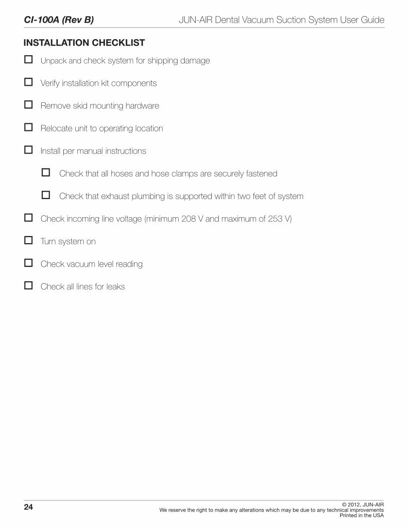
INSTALLATION CHECKLIST
o Unpack and check system for shipping damage
o Verify installation kit components
o Remove skid mounting hardware
o Relocate unit to operating location
o Install per manual instructions
o Check that all hoses and hose clamps are securely fastened
o Check that exhaust plumbing is supported within two feet of system
o Check incoming line voltage (minimum 208 V and maximum of 253 V)
o Turn system on
o Check vacuum level reading
o Check all lines for leaks