installing a ptv inlet - · pdf fileinstalling a ptv inlet install the new inlet 9. loosen the...
TRANSCRIPT

Installing a PTV Inlet
Agilent 6850 Series II Network GC System
Accessories G3345B (Septumless)and G3346B (Septum)
There are kits for installing both septum and septumless PTV inlets. This document describes both installations.
Each kit contains:
Description Quantity
Round grommet, small black 1
Round grommet, large blue 6
M4 machine screw, 12 mm 16
M4 hex nut w/lockwasher, 3.2 mm 1
Cable ties 6
Antistatic pouch 1
Disposable wrist strap 1
Insulation block 1
Extension cable 1
Top cryo bracket 1
Bottom cryo bracket 1
Eyelet 4
Inlet chassis 1
LC02 cryo assembly 1

Installing a PTV Inlet
*The inlet is factory-assembled. Do not disassemble it during installation.
EPC septumless head PTV inlet assembly (G3345B)* orEPC septum head PTV inlet assembly (G3346B)*
1
Ship kit 1
• Lowbld septa 5, 11-mm 1
• Open-end wrench, 6-mm 1
• Open-end wrench, 5-mm 1
• 1/4 Brass union 1
• OEM ship kit 1
Installation sheet (this document) 1
Description Quantity
2

Installing a PTV InletKit Contents
Kit Contents
Top cryo bracket
Bottom cryo bracket
Extension cable
LCO2 cryo assembly
Insulation block
Inlet chassis
Screws, grommets, eyelets, nut
PTV inlet
Flow module
Covered board assembly
3

Installing a PTV InletRequired Tools
Required Tools• T-20 Torx® screwdriver
• 7/16-inch open end wrench
Overview
Caution Before starting, review the safety information listed at the end of this document.
1. Prepare the GC.
2. Remove the existing inlet.
3. Install the new inlet.
4. Restore the GC to operating condition.
4

Installing a PTV InletPrepare the GC
Prepare the GC
WARNING Note the following warnings:
• Use extreme caution when working with cryogenic liquids. They can cause very serious burns requiring emergency medical attention. Before separating fittings, always bleed lines containing cryogenic fluids to atmospheric pressure. Wear safety glasses and cover the fittings with a towel when separating them.
• Before working on an instrument, disconnect the power cord to avoid a potentially dangerous shock hazard. Hazardous voltages are present in the instrument whenever the power cord is connected.
• Pressurized liquid CO2 is a hazardous material. Take precautions to protect personnel from high pressures and low temperatures. CO2 in high concentrations is toxic to humans; take precautions to prevent hazardous concentrations. Do not use copper tubing or thin-wall stainless steel tubing with liquid CO2. Both harden at stress points and may explode. Consult your local supplier for recommended safety precautions and delivery system design.
Caution Do not use liquid CO2 as a coolant for temperatures below –40 °C. The expanding liquid may form solid CO2—dry ice—in the GC oven. If dry ice builds up in the oven, it can seriously damage the GC.
To prepare the GC:
1. Turn off the GC and unplug the power cord. Allow time for all heated zones to cool.
2. Open the lid. If a column is installed, disconnect it at the detector end. Remove the nut warmer, insulation, and capillary adapter, if present. Close the lid.
5

Installing a PTV InletPrepare the GC
3. Turn all gases off at their sources. Disconnect the carrier and detector gas tubing from the back panel of the instrument.
4. Remove the lid top cover.
Disconnect gas supply tubingfrom these fittings
Lid top cover, withoutvalve box accessory
Remove T-20 Torxscrews (8 places)
Remove detectorcover
Remove vent tubing,if present
6

Installing a PTV InletRemove the existing inlet
Remove the existing inlet
Caution As part of this step and those that follow, you must bend various sections of tubing. Make the bends gradual and avoid kinks.
Caution It is neither necessary nor advisable to separate the inlet from its pneumatics module. Doing so can create leaks. Although handling the inlet and pneumatics module as a unit is awkward, it can be managed.
Caution This procedure requires precautions against electrostatic discharge. Use the grounded wrist strap (part number 9300-1408) and connect it to a bare metal surface of the GC. Failure to heed this caution may result in damage to the instrument or to the PTV assembly.
1. Loosen the screws holding the connector cover plate next to the inlet flow module.
2. Slide the cover plate off and disconnect the cable from the flow module.
3. Disconnect the gas fitting on the rear of the flow module.
4. Remove the three screws on top of the flow module.
(1) Loosen(3) Disconnect
(4) Remove
(2) Slide
7

Installing a PTV InletRemove the existing inlet
5. Complete the appropriate following steps (based on the type of inlet you are removing) to finish removing the inlet.
Cool On-Column inlet
a. Use a T-20 Torx screwdriver to loosen the three captive screws that attach the inlet weldment to the top of the inlet carrier.
b. Slide the inlet up and out of the carrier. If necessary, you can also slide the insulation sleeve off of the bottom of the inlet.
Purged Packed inlet
a. Trace the heater/sensor cable from the inlet to the wiring harness connector. Disconnect it.
b. Remove the three screws holding the inlet.
c. Lift the inlet and flow module out of the lid. Remove the insulation from the hole under the inlet.
Programmable Temperature Vaporization inlet
a. Lift up the PTV inlet.
b. Disconnect the power cable, thermocouple connector, and cryo connector from the flow module and board. Disconnect the module ribbon cable from the pneumatics board.
c. Slide the flow module out of the chassis, remove the chemical trap assembly from the mounting bracket, and remove the PTV assembly from the GC.
8
Installing a PTV InletRemove the existing inlet
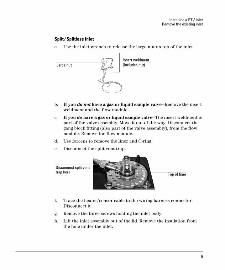
Split/Splitless inlet
a. Use the inlet wrench to release the large nut on top of the inlet.
b. If you do not have a gas or liquid sample valve—Remove the insert weldment and the flow module.
c. If you do have a gas or liquid sample valve—The insert weldment is part of the valve assembly. Move it out of the way. Disconnect the gang block fitting (also part of the valve assembly), from the flow module. Remove the flow module.
d. Use forceps to remove the liner and O-ring.
e. Disconnect the split vent trap.
f. Trace the heater/sensor cable to the wiring harness connector. Disconnect it.
g. Remove the three screws holding the inlet body.
h. Lift the inlet assembly out of the lid. Remove the insulation from the hole under the inlet.
Large nutInsert weldment(includes nut)
Top of liner
Disconnect split venttrap here
9

Installing a PTV InletInstall the new inlet
Install the new inlet1. Insert the inlet chassis into the inlet opening in the top of the GC. As
you face the front of the GC, the raised edge of the chassis is on the left.
2. Fit the insulation cup into position on the inlet body. Be sure the slot in the insulation cup is properly fitted with the inlet.
3. Place the inlet flow module into position. Be sure that the lip at the bottom of the flow module fits into the slot in the bottom of the flow module opening. See the picture with Step 5.
Inlet with insulation cup
Slot
Flow module
10

Installing a PTV InletInstall the new inlet
4. With the flow module in place, insert the inlet and insulation cup into the inlet chassis. Fasten the inlet and chassis into position with threeT-20 Torx screws.
5. Route the inlet tubing as shown. At the rear of the GC, follow the "C" (carrier) tubing. Using three or four cable ties, tie the inlet tubing with the other tubing found under the lid at evenly spaced intervals. Be careful to avoid bending the tubing sharply. Close the lid.
Inlet chassis
Screws
Inlet tubing
Lid
Inlet tubing tied together
Flow module
four places (circled)
11

Installing a PTV InletInstall the new inlet
6. Place the covered board assembly into position as shown. Fasten the assembly down with two screws.
On top of the lid, insert the captive screw into one of the vent holes in the covered board assembly. Beneath the lid, fasten the hex nut onto the captive screw.
7. Close the lid.
Covered board assembly
ScrewCaptive screw
Screw
(along side the coverin a vent hole)
Captive screw and hex nut
12

Installing a PTV InletInstall the new inlet
8. Attach the red cryo extension cable connector to the covered board assembly as shown. Run the loose end of the cabling behind the inlet flow module and to the rear of the inlet flow module. Be sure to plug the center connector’s positive and negative sides correctly.
Red cryo extension cable
Covered
Center connector negative Center connector positive
board assembly
connector
13

Installing a PTV InletInstall the new inlet
9. Loosen the screws on the detector module and move it forward far enough to lower the cryo extension cable connector through the top of the lid. Tie the red cable in with the other wiring, leaving as much slack as possible to avoid straining the soon-to-be-made connection.
10. If you WILL NOT be installing the Cryo kit, prepare the bottom bracket by inserting the six blue grommets into the holes. Insert the four brass eyelets into the top four grommets as shown.
If you ALREADY have installed the Cryo kit, disconnect the coolant outlet union (see the picture with Step 12) and remove the screws on the bracket to pull it far enough away from the GC to proceed with Step 11.
Red cable
Grommets (4) with eyelets
Grommets (2) only
Install PTV valvehere
14

Installing a PTV InletInstall the new inlet
11. Attach the cryo valve onto the lower-left position of the cryo bracket, including the screws to hold it in place.
Screws
15

Installing a PTV InletInstall the new inlet
12. Prepare to fasten the cryo bracket into place by first pulling the cryo valve tubing and wires through the hole on the side of the GC. You may not have the upper valve pictured below if you do not have the Cryo kit installed.
Coolant outlet union
16

Installing a PTV InletInstall the new inlet
13. Place the cryo bracket over the four mounting holes on the left side of the GC. Insert screws through the brass eyelets and secure them loosely. Reattach the coolant outlet union.
Mounting holesw/bracket in place
17

Installing a PTV InletInstall the new inlet
14. Open the lid and connect the valve wiring to the previously-routed red cryo extension cable connector inside the left panel of the GC.
PTV valve wire/red cable connect
Extension cable
Cryo valvetubing
18

Installing a PTV InletRestore the GC to operating condition
15. Route the cryo valve tubing around the counterbalance cam to the back of the GC to meet the inlet tubing you routed in Step 5. Use a couple of cable ties to tie the tubing together. Connect the tubing.
16. Continue installing the Cryo kit, if applicable. See the documentation that came with that kit for more information.
17. Close the lid and put the top cryo bracket on.
Restore the GC to operating condition1. Install the capillary adapter, if used.
2. Restore the column connection.
3. Install the lid top cover.
4. Restore carrier and other gases to the instrument.
5. Restore power.
6. Apply your normal operating pressures. Leak-check the manifold, back panel, and column fittings.
Counterbalance
Inlet tubing
Lid
cam
fitting
Cryo tubing
19

permission is prohibited, except as allowed under the copyright laws.
© Agilent Technologies, Inc. 2004
All Rights Reserved. Reproduction, adaptation, or translation without
Part number G3345-90007First Edition, July 2004Printed in USA
Agilent Technologies, Inc.2850 Centerville RoadWilmington, DE 19808-1610
Safety SymbolsWarnings in the manual or on the instrument must be observed during
comply with these precautions violates safety standards of design and
liability for the customer’s failure to comply with these requirements.
In the manualA warning calls attention to a condition or possible situation that could
A caution calls attention to a condition or possible situation that could
all phases of operation, service, and repair of this instrument. Failure to
the intended use of the instrument. Agilent Technologies assumes no
cause injury to the user.
damage or destroy the product or the user’s work.
AcknowledgementsTorx® is a U.S. registered trademark of Textron, Inc.
G3345-90007
On the instrument
See accompanying instructions for more information.
Indicates a hot surface.
Indicates hazardous voltages.
Indicates earth (ground) terminal.
Indicates explosion hazard.
Indicates radioactivity hazard.
Indicates electrostatic discharge hazard.
Pinch hazard.