institute for pulsed power and microwave technology
TRANSCRIPT

Annual Report 2013
Institute for Pulsed Power and Microwave Technology
Jahresbericht 2013
Institut für Hochleistungsimpuls- und Mikrowellentechnik (IHM)
Editor: John Jelonnek

Part of this work was supported by ITER Organization under the service contract No. ITER/CT/12/4300000720. The views and opinions expressed herein reflect only the author’s views. The ITER Organization is not liable for any use that may be made of the information contained therein.
Part of this work, supported by the European Communities under the contract of association between EURATOM and KIT, was carried out within the framework of the European Fusion Development Agreement. Part of this work is supported by EFDA under Task WP13-IPH-A07-P1-01/KIT/PS, Task WP13-IPH-A11-P1-01/KIT/PS and Task WP13-PEX-P01+02+03b/KIT/PS.
Part of this work, supported by the European Communities under the contract of association between EURATOM and KIT, was carried out within the framework of the European Fusion Development Agreement. Part of this work is supported by Fusion for Energy under Grants F4E-GRT-432, GRT-315 and OPE-458 and within the European GYrotron Consortium (EGYC). EGYC is a collaboration among CRPP, Switzerland; KIT, Germany; HELLAS, Greece; IFP-CNR, Italy. The views expressed in this publication do not necessarily reflect the views of the European Commission.

- 1 -
The Institute for Pulsed Power and Microwave Technology (Institut für Hochleistungsimpuls- und Mikrowellentechnik (IHM)) is doing research in the areas of pulsed power and high power microwave technologies. Both, research and development of high power sources as well as related applications are in the focus. Applications for pulsed power technologies are ranging from material processing to bioelectrics. High power microwave technologies are focusing on RF sources (gyrotrons) for electron cyclotron resonance heating of magnetically confined plasmas and on applications for material processing at microwave frequencies.
IHM is doing research, development, academic education, and, in collaboration with the KIT Division IMA and industrial partners, the technology transfer. IHM is part of the Helmholtz Association (HGF). During ongoing HGF POF2 period (2009 – 2014), projects are running within following six HGF programs: Renewable Energies (EE), FUSION, NUKLEAR, NANOMIKRO, Efficient Energy Conversion and Use (REUN) and Technology-Innovation and Society (TIG).
During 2013, R&D work has been done in the following topics: fundamental theoretical and experimental research on the generation of intense electron beams, strong electromagnetic fields and their interaction with biomass, materials and plasmas; application of these methods in the areas of energy production through controlled thermonuclear fusion in magnetically confined plasmas, in material processing and in energy technology.
Mentioned research areas require additionally the profound knowledge on modern electron beam optics, vacuum technologies, material technologies, high voltage technologies and high voltage measurement techniques.
The 2013 R&D program of the IHM is summarized in more detail as follows:
Department for Pulsed Power Technologies: (Head: Prof. Dr.-Ing. Georg Müller)
In environmental- and bio-technology the research and development is devoted to pulsed power technology with repetition rates up to 20 Hz, power in the Giga-Watt range and electric field strengths of 105-107 V/m. The research is concerned with short pulse (µs) - and with ultra-short pulse (ns) treatment of biological cells (electroporation). The focus is related to large-scale applications, treatment of large volumes, to the realization of a high component life time and to the overall process integration. Main directions of work in this field are the electroporation of biological cells for extraction of cell contents (KEA process), the dewatering and drying of green biomass, the treatment of micro algae for further energetic use and sustainable reduction of bacteria in contaminated effluents. Another key research topic is related to the surface modification
and corrosion protection of metals and alloys using high-energy, large-area pulsed electron beams (GESA process). The research is focused on electron beam physics, the interaction of electron beams with material surfaces and the corresponding material specific characterization investigations. The goal is to develop a corrosion barrier for improved compatibility of structural nuclear reactor materials in contact with heavy liquid metal coolants (Pb or PbBi). In the field of fusion research the activities are dealing with experimental and theoretical studies on the plasma-wall interaction at the first wall and divertor of tokamak fusion reactors. Numerical codes (TOKES and MEMOS) are further developed, applied and validated for prediction of the impact of transients on the erosion and lifetime of plasma facing components (PFCs) with the goal to improve reactor design (Programs: EE, NUKLEAR, FUSION).
– Pulsed electric field (PEF) treatment has been proven to be an appropriate technique for releasing intracellular components from microalgae. Compared to conventional mechanical cell disruption techniqes, the energy demand for PEF treatment is low and efficiency does not decrease at high microalge biomass concentrations in the suspension to be treated. For pilot-scale PEF processing of fresh microalgae biomass the construction of a 1000 l photobioreactor is almost completed.
– Growth stimulation by nsPEF exposure has shown to increase biomass yield of Chlorella vulgaris by 10% without admixing additives to the culture medium. Phytohormon admixture did not show synergetic behavior as it was obtained with clamydomonas reinhardtii the year before.
– A new effect of subsequent pulse exposure on single cells’ plasma membranes was identified by patch-clamp technique. The conductance of the recovered membrane increases with the number of pulse exposures. This is an indication for the existence of another permeabilization process - apart from pore formation - to be responsible for long term permeability effects provoked by pulsed electric field exposure. (Program: EE, HGF-Portfolio BioEconomy)
– Fe-Cr-Al alloys are of large interest for practical applications at high-temperatures in reactive environments, thanks to their corrosion resistance, which is due to the formation of an alumina protective scale at the surface and are therefore good candidates as protection barriers for the use in heavy liquid metals-HLM. To define the minimum Al content for the formation of an alumina scale in oxygen containing Pb, further investigations have been done in liquid Pb between 400 -600°C. An improved oxide map illustrating the stability domain of alumina grown on Fe-Cr-Al- alloys exposed to oxygen containing lead was drawn.
Institute for Pulsed Power and Microwave Technology
Institut für Hochleistungsimpuls- und Mikrowellentechnik (IHM)
Director: Prof. Dr.-Ing. John Jelonnek

- 2 -
– For the new version of the „Handbook on Lead-bismuth Eutectic Alloy and Lead Properties, Materials Compatibility, Thermal-hydraulics and Technologies“ which will be published by the OECD-NEA in 2014, a new version of the chapter on “Compatibility of Structural Materials with LBE (lead-bismuth eutectic) and Pb” have been elaborated. An extensive literature survey has been performed to consider all relevant data. For Up to now worldwide compatibility tests with a large variety of materials at varying conditions have been carried out both in stagnant and flowing LBE/Pb. By considering all data that are relevant for the judgment of material suitability for application in LBE/Pb cooled systems the operational windows for austenitic and ferritic/martensitic steels in dependence on oxygen content and temperature were determined. (Program: NUKLEAR).
– In the frame of different EFDA-tasks, a F4E-grant and an ITER Organization (IO) contract a variety of numerical simulations have been performed to support design activities for ITER and DEMO and experimental campaigns at JET. Analysis and computer simulation of disruption mitigation schemes of massive gas injection (MGI) have been done applying the numerical integrated tokamak code TOKES for 2-D and 3-D simulation of MIG radiation impact on beryllium first wall (FW). MEMOS was regular used to assist JET experiments in frame of the programs for ITER-like wall in which tungsten plasma facing component (PFC) surface melt motions under ELM impacts are under investigation. The MEMOS simulations allowed prompt estimations of the time intervals and heat loads needed for melting of a special lamella. Simulation results allowed reproducing of involved surface processes and the melt damage for the surface temperature measured at the lamella leading edge. The obtained surface temperature dependences on time and evaporation rates were used for cross-checks of measurements.
– To support the design of the ITER tungsten divertor MEMOS was used to analyse melting damage and erosion resulting from mitigated major disruptions, mitigated vertical displacement events (VDE) and major disruptions expected in ITER. Several scenarios of impact conditions specified by IO have been performed. With 2-D version of the code, damages to the castellated armour in the tungsten tile of ITER divertor dome under runaway electron impact were calculated. 3-D simulations for the W-tile of ITER divertor baffle were carried out for the downward VDE impact. In addition W droplet splashing in the magnetic field B at the edges of divertor baffle mono-block was estimated based on melt layer instabilities under the JxB force, with the current density J determined by eddy currents in PFC. (Program: FUSION).
Department for High Power Microwave Technologies: (Head: Dr. Gerd Gantenbein)
The High Power Microwave Department is focusing on RF sources (gyrotrons) for electron cyclotron resonance heating and current drive (ECRH&CD) of magnetically confined nuclear fusion plasmas and on the application of microwaves to chemical processes, materials and composites.
– Collaboration within the W7-X project PMW for planning, construction and testing of the 10 MW CW, 140 GHz electron cyclotron resonance heating (ECRH) system for the stellarator W7-X at IPP Greifswald. In particular, the 1 MW CW, 140 GHz gyrotrons have been developed in cooperation with EPFL-CRPP Lausanne and Thales Electron Devices (TED), Vélizy, France. In 2013, SN7 has been delivered to KIT for first FAT tests, but resent to Thales for refurbishment. Additionally, the FAT acceptance test of the refurbished tube SN5R2 has started. First long-pulse tests with 500 kW at 1800 s have been very successful, but long-pulse experiments at full power (1 MW / 10 s) ended with a damage of the output window. At the end of 2013, SN2i has been available at KIT. First tests are expected for begin of 2014. Finalization date for the 10 MW ECRH system is targeted for 2014. The quasi-optical transmission system and the high-voltage modulators for the gyrotrons have been developed in cooperation with IGVP, University of Stuttgart. With the development of major components for the ECRH system KIT makes a significant contribution to W7-X (Program FUSION).
– Within the European GYrotron Consortium (EGYC) and in collaboration with its industrial partner Thales Electron Devices (TED), Vélizy, France, EGYC is developing gyrotrons for the International Thermonuclear Experimental Reactor (ITER). According to a change in the delivery strategy for ITER, Europe will provide a total of 6 MW CW RF power at 170 GHz for the 24 MW CW ECRH system. Fusion for Energy (F4E) is coordinating the project. Institutional partners are CNR, Italy, EPFL-CRPP, Switzerland and HELLAS, Greece. In 2013, the procurement for the 1 MW 170 GHz short-pulse gyrotron has been signed. The manufacturing of the different components for the short-pulse gyrotron is well in plan. The final assembly is planned for September 2014 latest.
– Despite the switch to 1 MW conventional-cavity gyrotrons for the first delivery of ITER, KIT is pushing forward the development of multi-MW (2 MW) coaxial-cavity gyrotrons. In 2013, significant improvements in the stability of the operation of the 2 MW short-pulse gyrotron have been made. The root-causes for low-frequency oscillations have been found and corrected. The reason for former electron beam instabilities has been identified. Related improvements led to a new world record in gyrotron output power of 2.3 MW at 30 % efficiency (w/o SDC).
– Future fusion experiments will require frequency step-tunable gyrotrons. A step-tunable 1 MW gyrotron (105-163 GHz), including a microwave

- 3 -
vacuum window made of synthetic CVD-diamond for future ECRH systems of large-scale tokamak experiments is under test. In 2013, an experimental and theoretical study on the influence of the lateral misalignment between the axis of the annular electron beam and the cavity has been performed.
– The test stand of the 10 kW / 28 GHz gyrotron has been nearly completed in 2013. All relevant gyrotron components, including the first conventional cathode have been delivered and assembled. The tube has been tested for vacuum tightness already. Based on that, first RF tests are expected for begin of 2014.
– In 2013, significant steps in the theoretical investigation of thermo-mechanical behavior of high-loaded gyrotron components have been done. Targets have been lifetime estimations for the collector of the EU 1 MW gyrotron for ITER and thermo-mechanical simulations for the cavity.
– Regarding code development and simulation, code improvements have been done for the self-consistent codes EURIDICE and the electron optics code ESRAY. In particular, a new concept for broadband conditions for the cavity interfaces has been proposed. Intensive calculations on ACI have been done. Several different interaction codes have been involved in these simulations.
– Velocity spread of the electron beam from the Magnetic Injection Gun (MIG) is one of the most important factors that decreases the efficiency of gyrotron and facilitates mode selection in the cavity. Therefore, intensive studies on the influence of the emitter microstructure on the performance of a gyrotron have been done. New theoretical models have been proposed.
– KIT has continued its investigations on advanced gyrotrons for future DEMO. Target is the design of an 240 GHz, 1.5 MW, CW gyrotron with frequency step-tunability and the possibility for operation at 170 GHz and 204 GHz additionally. In 2013, a first selection of the operating mode has been done. The basic physical structure has been discussed.
– A new emission test device for verification of emitter uniformity has been built and tested in 2013. First results for an existing W7-X emitter have been presented.
– Sintering of advanced functional and structural ceramics, in particular of nanostructured ceramics and metal powders and process technology in nano-mineralogy by means of high power millimeter waves at a frequency of 30 GHz delivered by a gyrotron. In further experiments, fundamental new non-thermal microwave effects are validated (Program NANOMIKRO).
– System studies on microwave applicators for various applications at the ISM (Industrial, Scientific, Medical) frequencies 0.915 GHz, 2.45 GHz and 5.8 GHz, such as for energy-efficient production of aircraft components made of carbon fibre composites by microwave process technology at 2.45 GHz. The new HEPHAISTOS CA3 system with a payload capacity of 7000 l and a microwave power
of 25 kW is already in routine operation. This will, in development with industry, offer various applications and processes on a service basis. With the new facilities of the 2.45 GHz HEPHAISTOS-line significantly shorter processing times at slightly improved material properties compared with the conventional production in autoclaves have been achieved (Programm REUN, TIG and IMA).
Equipment, Teaching Activities and Staff
IHM is equipped with a workstation cluster and a large number of experimental installations: KEA, KEA-ZAR, three GESA machines, eight COSTA devices, one abrasion and one erosion teststand, two gyrotron test facilities with one common power supply and microwave-tight measurement chamber, one compact technology gyrotron (30 GHz, 15 kW, continuous wave (CW)), several 2.45 GHz applicators of the HEPHAISTOS series, one 0,915 GHz, 60 kW magnetron system, one 5.8 GHz, 3 kW klystron installation and a low power microwave laboratory with several vectorial network analysers.
The project FULGOR, targeting for a renewal of the KIT gyrotron teststand is progressing. In 2013, an agreement on the project structure including the involvement of the KIT project and quality management has been achieved. The final start of the procurement of the equipment is planned for 2014.
Prof. John Jelonnek has continued to teach the new lecture course entitled “High Power Microwave Technologies (Hochleistungsmikrowellentechnik)” for Master students at KIT. Dr. Gerd Gantenbein has been teaching the part “heating and current drive” of the lecture “Fusionstechnologie B” by Prof. R. Stieglitz, IFRT. Dr.-Ing. Martin Sack hold the lecture course “Elektronische Systeme und EMV” at KIT.
At the turn of the year 2013/2014 the total staff with regular positions amounted to 40 (17 academic staff members, 4 engineers and 19 technical staff member and others).
In addition 12 academic staff members and 11 technical staff members (and others) were financed by acquired third party budget.
In course of 2013, 6 guest scientists, 8 PhD students (1 of KIT-Campus South, 3 of KIT-Campus North, 4 Scholarship), 3 DHBW student and 4 trainees in the mechanical and electronics workshops worked in the IHM. 7 Master students have been hosted at IHM (3 of ETIT faculty, 1 of Mechanics faculty, 2 DAAD-IIT scholarship, 1 of University of Bordeaux, France). 1 Erasmus student has been at IHM during 2013.
Strategical Events, Scientific Honors and Awards
In September 2013 Dr. Georg Müller has been appointed Professor for Pulsed Power in the Faculty of Electrical Engineering and Information Technology (ETIT) of KIT. Prof. Müller will start to give lectures on pulsed power technologies and applications in 2014.
Prof. Müller was elected as a member to the international IEEE-Pulsed Power Science and Technology Committee (IEEE-PPS&T).
- 4 -
Prof. Müller has been appointed as member of the International Research Board of the National Research Tomsk Polytechnic University.
IHM has organized:
The 25th Joint Russian-German Workshop on ECRH and Gyrotrons (STC-Meeting) which took place at Karlsruhe/Stuttgart/Garching in June. Chair has been Dr. Dietmar Wagner in cooperation with IHM.
The Workshop on RF Heating Technology of Fusion Plasmas 2013 (US-EU-JPN RF Heating Technology Workshop) which took place in Speyer in September. Chair has been Dr. Gerd Gantenbein.
The 10th International Bioelectrics Symposium which took place in Karlsruhe in September. Chair has been Dr. Wolfgang Frey.
All workshops/symposia have been counted as very successful events.
Prof. Manfred Thumm received a “Letter for Appointment” granted to his appointment as a member of International Advisory Committee of Cooperative Innovation Centre of THz Science for his outstanding academic achievements.
Mrs. Martina Huber received the yearly award of the “Freundeskreis des FZK” for her excellent achievements in organizing the different events at IHM and her great sensitivity, creativity and enthusiasm for the administrative needs at IHM.
Longlasting Co-operations with Industries, Universities and Research Institutes
Basics of the interaction between electrical fields and cells (Bioelectrics) in the frame of the International Bioelectrics Consortium with Old Dominion University Norfolk, USA; Kumamoto University, Japan; University of Missouri Columbia, USA; Institute Gustave-Roussy and University of Paris XI, Villejuif, France; University of Toulouse, Toulouse, France, Leibniz Institute for Plasma Science and Technology, Greifswald, Germany
Desinfection of hospital wastewater by pulsed electric field treatment in cooperation with University of Mainz and Eisenmann AG
Integration of the electroporation process for sugar production with SÜDZUCKER AG
Development of protection against corrosion in liquid metal cooled reactor systems in the following EU-Projectes: LEADER, GETMAT, MATTER, SEARCH (Partner: CEA, ENEA, SCK-CEN, CIEMAT)
Development of core- and structure materials for liquid lead reactor cooling systems in collaboration with the Japanese Atomic Energy Agency (JAEA)
Development of large area pulsed electron beam devices in collaboration with the Efremov Institute, St. Petersburg, Russia
Experiments on liquid Pb and PbBi-cooling of reactor systems with the Institute for Physics and Power Engineering (IPPE), Obninsk, Russia
Development, installation and test of the complete 10 MW, 140 GHz ECRH Systems for continuous wave operation at the stellarator Wendelstein W7-X in collaboration with the Max-Planck-Institute for Plasmaphysics (IPP) Greifswald and the Institute of Interfacial Process Engineering and Plasma Technology (Institut für Grenzflächenverfahrens-technik und Plasmatechnologie, IGVP) of the University of Stuttgart
Development of the European ITER Gyrotrons in the frame of the European GYrotron Consortium (EGYC) and coordinated by Fusion for Energy (F4E). The other members of the Consortium are CRPP, EPFL Lausanne, Switzerland, CNR Milano, Italy, ENEA, Frascati, Italy, HELLAS-Assoc. EURATOM (NTUA/NKUA Athens), Greece. The industrial partner is the microwave tube company Thales Electron Devices (TED) in Paris, France
Development of new diagnostic systems for improvement of electron guns for gyrotrons and cavity interaction calculations in collaboration with the St. Petersburg Polytechical University, Russia and the University of Latvia, Latvia
Basic investigations of plasma-wall interaction in fusion reactors in collaboration with the State Research Center of Russian Federation Troitsk Institute for Innovation and Fusion Research (TRINITI), Troitsk, Russia and the Institute of Plasma Physics, Kharkov, Ukraine
Fundamentals of application of gyrotrons for microwave materials processing in collaboration with the National Institute for Fusion Science (NIFS) in Toki, Japan and the University of Fukui, Japan
Development of Microwave Systems of the HEPHAISTOS Series for materials processing with microwaves with the Company Vötsch Industrietechnik GmbH, Reiskirchen.

- 5 -
HGF program: FUSION
– Plasma Wall Interaction (PWI) –
EFDA Task WP13-IPH-A07-P1-01/KIT/PS: Analysis and computer simulation of disruption mitigation schemes of massive gas injection (MGI)
The major disruptions expected in future tokamaks would produce plasma losses of high power which locally damage the plasma facing components (PFC). In ITER, to reduce the plasma impact a massive gas injection (MGI) of a noble gas into the confined plasma at the disruption onset is going to be applied. During MGI the confined thermal energy transforms into photonic radiation which loads the surface more evenly than the plasma fluxes do. The disruption development lasts for a small fraction of second so that the cooling time c of MGI thermal quench (TQ) less than ~10 ms is required. The plasma cooling occurs due to ionization of injected atoms (‘G-atoms’) and following formation of radiating cooling wave which moves into plasma bulk.
The KIT activity for this task concerns further development and the applications of the numerical integrated tokamak code TOKES for 2D- and 3D-simulation of MGI radiation impact up to surface melting of beryllium first wall (FW) (Fig below). A number of validation and scoping calculation scenarios have been performed for JET and ITER aiming at optimization of the amount of injected gas within the c and melt free limits.
Left: ITER vacuum vessel, magnetic flux coordinates of TOKES, wall surface coordinate X [m] and available injector locations are shown. Right: The maximum inflow Jm determines the MGI process. The gas inflow J(t) is calculated with TOKES.
Comparison of line integrated density [1018 m-2] for 77806 and 77808 JET deuterium discharges (in red) with the validated TOKES simulations (in blue). The vertical line indicates maximum time [s] after which the diagnostics fail.
TOKES MGI simulations have been validated against JET experiments: for the discharges #76314 (neon MGI) and #77806, #77808 (argon MGI). Line integrated plasma densities obtained with 2D version of TOKES during MGI are compared with corresponding experimental data. A reasonable fitting of experimental and simulated time dependences is obtained for electron densities in the time interval when the experimental data is valid (figure on the left side). The difference of 30 % can be attributed to 2D nature of simulations and 3D experimental conditions. For #77806 a parametric study for c by decreasing argon amount has been performed with TOKES. We found that the discharge interruption can be provided until the amount of injected gas reduces by 40 times from the experimental value 5.61022 atoms. As MGI with small gas amounts increases the probability of generation of runaway electrons (RE), for ITER special sacrificing diaphragm for mitigation of RE damage to FW is proposed.
The main current TOKES development is implementation of 3D model for the plasma and radiation emission in order to obtain toroidal peaking of radiation load in a vicinity of injector as a function of time and Jm. Now this work is in the stage of simplified plasma modelling being focussed mainly for 3D radiation load distribution near injector orifice in FW surface. Visualization tools for 3D magnetic field configuration are developed and for pre-TQ phase 3D results for single toroidally discrete upper port neon injector achieved (see figure below). We obtained that the melting threshold Jm,thr 0.61026 atom/s on Jm is smaller by a factor of 4 in comparison with that of 2D model, and the corresponding c 9 ms is 2 times larger.
Toroidal-poloidal distribution of radiation load over the wall surface is shown at the time 3.2 ms after opening the valve of single upper port neon injector, which is the moment of maximum wall temperature Tw, with Tw,max = Tmelt,Be = 1560 K. In addition, the change of magnetic field before and behind the cooling wave was analysed in cylinder geometry, as first stage of addressing magnetic energy contribution in tokamaks to the radiative wall load. The magnetic energy releases in the cooling front as the Joule heat and then transfers there into the radiation. The estimated magnetic energy can be the factor of 3.5 larger than that of plasma thermal energy. Negligibly

- 6 -
small cross-motion of magnetically frozen plasma before the cooling front was obtained.
F4E Grant GRT-315: Simulation of ITER first wall energy loading during mitigated disruptions and runaway electrons
This collaboration between KIT and the ITER organization (IO) for numerical prediction of melt free margin of neon MGI mitigated disruptions and RE impact damage to FW is now finished. The last results are obtained in 2013 with 2D version of TOKES and with the code MEMOS. The TOKES simulations focussed upon the mid-plane injector and two equal simultaneously acting injectors located at the upper-port and the mid-plane. The last MEMOS simulations concern diverse cases of RE impacts and also possible melting of stainless steel (St-St) inserts into FW under the radiation loads produced by TOKES.
With TOKES we calculated six scenarios of neon MGI: three cases for the mid-plane injector and three cases with two injectors, for the regimes with Tw,max about Tmelt,Be. Typical maximal radiation load onto the wall is of 0.5 MJ/m2 (see figure below)
Poloidal plane distribution of radiation losses (rainbow colour scale, the radiating wave is mainly green), electron temperature Te (red tints from both sides of the wave) and wall surface load (in blue) are shown for the case Jm = 21.31026/s at 1.9 ms. At this moment halve of thermal energy (~2102 MJ) is transformed into the radiation. In front of mid-plane injector the melting is indicated (in pink).
Comparison of three injector configurations: upper port injector, mid-plane injector, and two injectors (‘upp-mid’). The melting threshold is indicated e.g. with green vertical arrow for the mid-plane injector case.
Three injector configurations are compared (figure on the left side). The linear extrapolations of calculated cooling time c(Jm) give the c at the melting threshold on Jm. (At the melting threshold the curve of calculated maximum wall surface temperature Tw is crossing the constant of Be melting point.) The conclusion is drawn that the melting threshold Jm,thr of the mid-plane injector case is substantially smaller (by the factor 0.6) and the cooling time is also smaller (by 20%) in comparison with the upper port injector case. Small Jm,thr is an advantage of the mid-plane location. The mid-and-upper injector configuration has the maximal melting threshold among the considered three cases (factor 2 compared to the upper port injector) however it is an advantage that the cooling time c is smaller (by ~20-30%) than c in both other cases.
The MEMOS calculations for St-St PFC demonstrated that for equal loads the temperature of St-St PFC is higher than that of Be. Above the melting thresholds on the median inflow Jm, the melt pool in St-St is deeper than that of Be by approximately a factor of 2. The melted St-St phase exists much longer than the melted Be phase. However the thresholds for St-St and Be are approximately equal to each other: Jm,thr 2.21026/s.
In the RE simulations, geometric peculiarities of ITER upper FW modules in “single roof” and “double roof” configurations provided by IO and F4E (two next Figs.) are implemented into MEMOS and the Monte Carlo code ENDEP. Predictive simulations for beryllium and tungsten PFC are performed in order to estimate after effects of “fast” and “slow” RE impacts as well as melting threshold on RE beam current density JRE.
The cross-section through the double roof ITER FW panel is shown. The axis t means toroidal direction.
The implemented single roof Be tile of the FW module The fast impact corresponds to load duration RE ~0.1 ms, The Be threshold JRE,Be is in the range 0.25 - 0.48 MA/m2, which depends on RE spectrum. A small increase of JRE by 10-20 % above JRE,Be results in surface melting up to 0.7 mm with the resolidification time longer than 30 ms. For tungsten PFC, JRE,W of the fast impact is of ~0.2 MA/m2. The small increase of JRE above JRE,W results in the W melting up to 0.3 mm with the resolidification time smaller than 4 ms.
For all slow impact cases (IO specified them in terms of RE from 10 ms to 0.2 s) the heat loads Q (specified from 0.34 to 46 MW/m2) are obtained to significantly

- 7 -
exceed the melting threshold and therefore severe melting damage to the Be and W FW tiles is expected (see figure below) especially for the long pulse durations. The melt pool depth can achieve several mm and the molten phase lasts up to several second, so that even the Cu-Cr-Zr tubes of the cooling system beneath the PFC can be damaged (the tubes locate at the deepness 1.3 cm from the PFC surface). The large resolidification time permits us to anticipate some pronounced splashing of melt layer.
Be (left) and W(right) melt pool depth against time t for Q = 2.3 MW/cm2 is shown. EFDA Task WP13-IPH-A11-P1-01/KIT/PS: Modeling of plasma wall interaction applying the melt motion code MEMOS
Main application of MEMOS was regular assisting for the JET experiments in frame of the programs M13-01 and M13-02 for the ITER-like wall (ILW) in which tungsten PFC surface melt motions under ELM impacts is under investigation. The MEMOS simulations allowed prompt estimations of the time intervals and heat loads needed for melting of the special lamella (see figure below). Simulation results allowed reproducing of involved surface processes and the melt damage for the surface temperature measured at the lamella leading edge. The modeling has been carried out for the JET H-mode reference discharge #84779 which supplied multiple ELMs heat loads of the frequency 30 Hz for the MEMOS input. The obtained in simulations surface temperature dependences on time and evaporation rates are used for cross-checks of measurements. As one of results, it is admitted that between MEMOS output and the measured parameters such as surface temperature a good qualitative and quantitative agreement achieved. Also the L-mode reference discharge #84514 was similarly analyzed.
The design of JET divertor lamellas used in MEMOS. The height of exposed edge of the special lamella (in magenta) is 2.4 mm.
Also the cooperation with the team of the plasma gun QSPA-Kh50 (IPP Kharkov, Ukraine) continued. The theoretical model for W melt splashing earlier developed in KIT basing on the Kelvin-Helmholtz (KH) instability was confirmed in the last IPP experiments with pulse duration 0.25 ms and the wall load Q 0.75 MJ/m2. The W droplet sizes, inverse proportionality of droplet velocity on Q and the resolidification wave profile correspond to the KH model. The droplets fly mainly the upstream direction of plasma stream. The W splashing during the plasma exposure is followed at the end of pulse by W dust emission.
EFDA Task WP13-PEX-P01+02+03b/KIT/PS: Effect of thermal loads on different modules of DEMO PFC
The thermal performance of different PFC modules was analysed for the DEMO reactor conditions in steady-state operation with the inclusion of ELM transients for mitigated (plasma load Q < 0.5 MJ/m2) and unmitigated (Q > 0.5 MJ/m2) cases. The heat transfer and armour erosion due to the plasma impact has been modelled applying the code MEMOS.
As an example the effect of these loads has been considered for the W alloy mono-block design with Cu OFHC/EUROFER water coolant tube first proposed in the framework of the PPP&T divertor study (see figure below). A variant of this design with EUROFER tube connected to the W block with a diamond/copper composite (DCC) used in the diagnostic windows, was also analysed. The optimal thicknesses of material layers, which allows keeping the maximum temperatures within allowable design limits under ITER water cooling conditions was found.
DEMO PFC tungsten mono-block module with cooling channel made of Cu OFHC or DCC and EUROFER In the calculations we use the specifications of power loads on the FW and the divertor during DEMO steady state operation with and without ELM pulses. The load power on the FW in the DEMO-I case is 0.5-1 MW/m2 and for DEMO-II it is estimated as 1-5 MW/m2. For the divertor, the heat loads are about 3 MW/m2 and 8.9 MW/m2 for the cases I and II, respectively. The expected power of Type I ELM is estimated assuming that the power fraction going to the FW is similar to that in ITER, and mitigated ELM has the amplitude as in ITER i.e. 0.5-1 MJ/m2. In the case I the uncontrolled ELM frequency is estimated as 0.8 Hz, peak deposition energy/deposition time to the FW and divertor plate are 0.1 MJ/m2/0.6 ms and 10 MJ/m2/1.2 ms, respectively. In the case II these parameters are assumed as

- 8 -
0.5 MJ/m2/0.6 ms and 20MJ/m2/1.2ms, respectively. The full power deposition consists of the sum of the steady state and the ELM power loads.
For unmitigated ELMs calculations show that W surface melts and evaporates at the ELM peaks (see figure below). However, the maxima of EUROFER, DCC and Cu alloy temperatures remain within the limits determined by DBTT from below and by the creep strength from above. Neutron irradiation of 5 dpa is assumed. A vapour shield near the surface screens the tube materials from excessive overheating.
Evolution of maximal surface temperature of the irradiated materials for unmitigated ELM loads is shown. The vertical bars mark the allowable temperature range of the materials
Evolution of maximal surface temperature of irradiated materials shown for mitigated ELM loads. The DEMO II divertor heat load is 8.9 MW/m² + 26 Hz•0.6 MJ/m². Critical flux to the coolant of 24 MW/m² is exceeded for operation time above 1.5sec. For mitigated ELM loads (the same times as it assumed in ITER) no W melting and evaporation occurs. However, due to the absence of vapour screening, we expect a large maximum heat flux at the coolant tube which can exceed the critical heat flux for the pressurize water reactor cooling range (Fig above). Because of high thermal conductivity of DCC the maximum temperature of materials and the coolant tube remain insensitive to DCC thickness variation and lie within the allowable temperature range for W. For DCC a thickness of 1 mm is chosen as optimal. The dependence of maximum material temperatures on the
EUROFER thickness at given W thickness w = 3 mm shows that in the range of EUROFER = 0.1-0.5 mm the temperatures remain within the allowable temperature limits. Calculations also show that the variation of W thickness affects only the W temperature and not the structured substrate.
For the cooling channel calculations the pressurized water reactor (PWR) conditions with about 325ºC (560 K) inlet water temperatures and pressure about 15,5 MPa are used. The water velocity about 20 m/s guarantees a reasonable margin to the critical heat flux without excessive pressure drop. The water temperature increase and pressure drop along the pipe depend on heat power. Heat exchange coefficient is calculated using the Sider-Tate correlation for forced convection regime and the Thom correlation for sub-cooled boiling regime.
ITER contract ITER/CT/12/4300000720: Melting Damage and Erosion Analysis of the ITER Tungsten Divertor
In frame of this contract, MEMOS simulations on the consequences of mitigated major disruptions (MD), mitigated vertical displacement events (VDE) and major disruptions expected in ITER have been performed for several scenarios of impact conditions specified by IO. With 2D version of the code, damages to the castellated armour in the tungsten tile of ITER divertor dome under runaway electron impact are calculated. 3D simulations for the W-tile of ITER divertor baffle (see the figure below) are carried out for the downward VDE impact. In addition W droplet splashing in the magnetic field B at the edges of divertor baffle mono-block is estimated based on melt layer instabilities under the JxB force, with the current density J determined by eddy currents in PFC.
Baffle geometry for 3D MEMOS simulations In the simulated ~20 scenarios in question the heat loads Q are expected to be so high that they cause severe surface melting of PFC. Simulations of MD and mitigated VDE are performed for as single as multiple events of different durations , they include melt layer motion and the vapour shield in front of the target.
To give examples, the simulations demonstrated that in case of mitigated MDs with Q = 45 MJ/m2 surface temperature Tw remains below melting threshold for all given from 3 to 10 ms. With Q = 70 MJ/m2 the temperature exceeds the melting threshold for < 9 ms, maximum depth of melt pool hm is about 70 µm. Tangential friction pressure pt of the impacting plasma causes a motion of melted material with the velocity

- 9 -
along the surface about 0.1-0.5 m/s. The melt motion produces mountains at PFC edges up to h+ ~ 25 µm height (per event) and craters depth h- ~ 10 m. For relatively low number of events (n < ~30) the surface damage magnitude h+ - h- linearly increases with n. At n > 30 the profile of surface roughness becomes complex and the magnitude cannot exceed few mm. Estimated critical velocity of melt splashing on the PFC edges due to the Rayleigh-Taylor instability is above 1 m/s thus pt is low enough to neglect the melt layer instability. Same nearly melt velocity is necessary for bridging of castellated PFC. The influence of halo current on the melt motion for given magnitudes of J is low e.g. the melt velocity increases for ~0.15 m/s and the changes of h+ and h- don’t exceed 3 µm per event.
For all scenarios of mitigated MDs and mitigated VDE the evaporation erosion is low (below 0.1 µm) and the shielding does not form. Only in case of major disruptions (Q > 300 MJ/m2) significant evaporation occurs and the shielding layer in front of the irradiated surface appears. For such cases hm can be about 0.1-0.2 mm. The main erosion mechanism is surface evaporation of few m of removed material per event, up to 6 µm at baffle edges. After many e.g. 10 events total baffle edge erosion increases up to 70 µm.
Staff involved
Dr. B. Bazylev, Dr. Yu. Igitkhanov, Dr. I. Landman, Dr. S. Pestchanyi
– Microwave Heating for W7-X (PMW) –
Introduction
Electron cyclotron resonance heating (ECRH) and current drive (ECCD) are the standard methods for localized heating and current drive in future fusion experiments. Thus, ECRH will be the basic day-one heating system for the stellarator W7-X which is currently under final construction at IPP Greifswald. It is expected that the ECRH system for W7-X will be finalized in 2014. In its first stage W7-X will be equipped with an 10 MW ECRH system operating at 140 GHz in continuous wave (CW).
The complete ECRH system is coordinated by the project “Projekt Mikrowellenheizung für W7-X (PMW)”. PMW has been established by KIT together with IPP and several EU partners in 1998. The responsibility of PMW covers the design, development, construction, installation and system tests of all components required for stationary plasma heating on site at IPP Greifswald. PMW coordinates the contribution from Institute of Interfacial Process Engineering and Plasma Technology (IGVP) of the University of Stuttgart too. IGVP is responsible for the microwave transmission system and part of the power supply (HV-system). IPP Greifswald is responsible for the in-vessel components and for the in-house auxiliary systems. PMW benefits from the collaboration with Centre de Recherche de Physique des Plasmas (CRPP) Lausanne, Commissariat à l´Energie Atomique (CEA), Cadarache and Thales Electron Devices (TED), Vélizy.
A contract between CRPP Lausanne, FZK Karlsruhe and TED, Vélizy, had been settled to develop and build the series gyrotrons. First step in this collaboration was
the development of a prototype gyrotron for W7-X with an output power of 1 MW CW at 140 GHz.
Seven series gyrotrons have been ordered from industrial partner Thales Electron Devices (TED), Vélizy. First operation and long pulse conditioning of these gyrotrons is being performed at the teststand at KIT. Pulses up to 180 s duration at full power are possible (factory acceptance test, FAT) whereas 30 minutes shots at full power are possible at IPP (necessary for site acceptance test, SAT). Including the pre-prototype tube, the prototype tube and the 140 GHz CPI-tube, in total 10 gyrotrons will be available for W7-X in final state. To operate these gyrotrons, in addition to the Oxford Instruments and Accel magnets, eight superconducting magnet systems have been manufactured at Cryomagnetics Inc., Oak Ridge, USA.
Most of the components of the transmission system, HV-systems and in-vessel-components have been ordered, manufactured, delivered and are ready for operation at IPP Greifswald. A part of the existing ECRH system has been already used to test new concepts and components for ECRH. A significant delay arose in the project due to unexpected difficulties in the production of the series gyrotrons.
Series Gyrotrons
In 2005, the first TED series gyrotron SN1 had been tested successfully at FZK and IPP (920 kW/1800 s). It met all specifications during the acceptance test, no specific limitations were observed. In order to keep the warranty SN1 has been sealed, one prototype gyrotron is routinely used for experiments.
Series gyrotrons following SN1 did show a more or less different behavior with respect to parasitic oscillations excited in the beam tunnel region. These oscillations resulted in an excessive heating of the beam tunnel components, in particular of the absorbing ceramic rings. The gyrotrons re-opened after operation showed significant damages due to overheating at the ceramic rings and the brazing of the rings. A possible solution was proposed and successfully tested by KIT. As the main difference to the usual beam tunnel this design features corrugations in the copper rings which handicap the excitation of parasitic modes.
The thermal loading of the collector depends on the interaction efficiency between the electromagnetic field and the electron beam. And, of course, it depends on the pulse length. For high power operation at continuous wave (CW) th thermal loading is close to what is feasible in terms of cooling and lifetime of the collector. For the series tubes a patented sweeping procedure has been introduced which combines a vertical and radial displacement of the electron beam at the collector. This results in an almost constant power deposition at the inner wall along the axis and removes the particularly dangerous temperature peaks at the lower and upper reversal points of the electron beam. Already in 2012 complete sweeping systems for the series gyrotrons have been procured.
Additional to the innovative collector sweeping, modifications have been realized and already tested in order to reduce the absorption of the internal stray radiation by covering stainless steel components with copper.

- 10 -
A possible corrosion in the water cooling circuit of the diamond window at the brazing structure is prevented by replacing the water by inert Silicon oil.
In 2013, the plan has been to achieve Factory acceptance (FAT) and Site Acceptance (SAT) of the series gyrotrons SN7 and SN5R2. SN7 has been delivered in January 2013 already. Short pulse operation showed 1 MW output power with an expected efficiency of 30 % without energy recovery at the collector. But, the measurement of the output beam quality showed a clear deviation from the specification which prevents the tube from long pulse operation. Low power RF measurements on a similar device and mechanical measurements confirmed a manufacturing failure of the internal surface of the quasi-optical mode transformer (launcher). The failure happened at the manufacturer of the launcher. Based on this, the complete gyrotron was taken back to the TED for repair.
As planned, the gyrotron SN5R2 has been repaired at TED (correction of the position of the mirror 3). Additionally, the tube has been updated according all improvements done for SN6. The tube has been taken into operation at KIT in October 2013. During short pulse tests, the tube SN5R2 showed very promising results comparable to the measurements done on SN6. The output beam quality has been in good agreement with the specification. During conditioning of the tube long pulse experiments with more than 500 kW output power and a pulse length of up to 30 min has been performed. Full power operation (1 MW) of the gyrotron has been stopped due to a defect in the CVD diamond window. The disassembling of the window unit and a failure analysis is ongoing.
At the end of 2013 the gyrotron SN2i has been delivered to KIT, operation of this tube will start in early 2014.
Transmission Line System
The transmission of the gyrotron output power to the plasma is performed via an quasi-optical system, which consists of single-beam and multi-beam waveguide (MBWG) elements, in total more than 150 reflectors. For each gyrotron, a beam conditioning assembly of four mirrors is used to match the gyrotron output to a Gaussian beam with the correct beam parameters, and to set the appropriate polarization needed for optimum absorption in the plasma. A fifth mirror directs the beam to the beam combining optics, which is situated at the input plane of a multi-beam wave guide. This MBWG is designed to transmit up to seven beams (five 140 GHz beams, one 70 GHz beam, and one channel connected to the N-port remote-steering launchers via switches) from the gyrotron area (entrance plane) to the stellarator hall (exit plane). To transmit the power of all gyrotrons, two symmetrically arranged MBWGs are used. At the output planes of the MBWGs, two mirror arrays separate the beams again and distribute them via two other mirrors and CVD-diamond vacuum barrier windows to individually movable antennas (launchers) in the torus.
The manufacturing and installation of the components of the basic transmission system has been completed, except for the beam-matching optics units and the “towers” which contain the mirrors in front of W7-X. In autumn 2013, access to the W7-X torus hall was given,
and the mounting of the towers could be performed. Both towers are in place with the required high positioning accuracy of a few Millimeters. The towers are equipped with the control units for remote control of the front steering launchers, the vacuum shutters, arc detectors and beam monitoring diagnostics. Data aquisition modules for slow and fast recording of W7-X relevant signals are installed.The installation and connection of cooling tubes to supply the mirrors and stray radiation absorbers in the towers is underway.
Work for beam diagnostics and power measurement of the gyrotron beams continued. Concepts for 2-frequency sensors were followed, and linearization amplifiers for the detectors were built. For the receivers attributed to the directional couplers on the mirrors M14, the conical scan mechanics and electronics for the alignment control were further developed.
For the THALES gyrotrons SN7 and SN5R2, which had been delivered to KIT for acceptance tests, beam characterization and phase retrieval was performed. Both gyrotrons finally were not accepted. SN7 had a strongly structured output beam with low Gaussian content as seen from the figure below (left) and high stray radiation, which prevented long puls operation. Nevertheless, the time until rejection of the tube was used to upgrade the PROFUSION program package, and to design phase-correcting surfaces for matching mirrors. As can be seen from the figure below, surfaces for the matching mirrors could be designed, which in principle – for perfect alignment and without aberration due to curved mirrors – allow a conversion of the gyrotron beam with a TEM00 contents as low as 80% to a good Gaussian beam with a mode purity of 97.7%.
From left to right: Gyrotron SN7 output beam profile at position of mirror M1; Phase profile for surface of M1; Phase profile for surface of M2; Beam profile on M2, with 97.7 % TEM00 contents. For investigations on trapped particles in W7-X as well as a demonstration for a reactor-compatible antenna for ECRH, two N-ports of W7-X will be equipped with remote-steering (RS) launchers. This is due to the fact, that front steering launchers as used in the A and E ports will not fit into these narrow ports. The remote-steering properties are based on multi-mode interference in a square waveguide leading to imaging effects. For a proper length of the waveguide, a microwave beam at the input of the waveguide (with a defined direction set by a mirror system outside of the plasma vacuum) will exit the waveguide (near the plasma) in the same direction. All R&D activities regarding the design, optimization, and production of the RSLs are being done within the frame of the Verbundprojekt "FORMIK3", with preferential funding by the BMBF. The project is running under leadership of IPP-Greifswald and coordinates the contributions of the research laboratories IGVP Stuttgart and IPP-Garching, and two industrial partners, Neue Technologien GmbH, Gelnhausen (NTG), and Galvano-T (G-T) electroforming-electroplating GmbH, Windeck.

- 11 -
In-vessel components
The four ECRH-plug-in launchers have been equipped with silicon oil manifolds for the cooling of the diamond disc vacuum barrier windows.
The vacuum measurement and pumping valves for each shutter, which is in front of each window, were also installed. The thermal isolation and the electric flange heating for the vacuum bake-out has been defined.
Cabling and pressured air connections have been completed.
The electron cyclotron absorption (ECA) diagnostics (128 waveguides), which measures the transmitted ECRH power, the beam position and polarization was assembled inside the plasma vessel. Eight compact amplifier boxes with 16 channels each have been manufactured at the IGVP Stuttgart University. These boxes have been mounted on the protection housing of the ECA-diagnostic outside the vacuum vessel.
The design of the immersion tubes for the video diagnostic has been finished and fabrication has started. Several cameras have been tested in the 3T magnetic field of a gyrotron magnet. A compact near infrared C-mos video camera was chosen to be installed in the immersion tubes.
The design of the microwave stray radiation monitors, so called sniffer probes, was finished. The manufacturing drawings are produced presently.
The required wide angle antenna sensitivity could be achieved by inserting a transmitting random phase plate (Schroeder diffuser) into the microwave optic system.
– ITER ECRH Advanced Source Development –
Introduction
EU is presently developing the 1MW, 170GHz conventional cavity gyrotron for ITER. The development of the 1 MW gyrotron was initiated in 2008 as a risk mitigation measure during the development of the 2 MW coaxial-cavity gyrotron. In the last year the scientific design of the 1 MW gyrotron components, such as the gun, beam tunnel, cavity, quasi-optical output coupler and single-stage depressed collector has been finalized. The EU gyrotron development plan is based on a single 1 MW, CW prototype. This prototype shall fulfill the main ITER requirements in terms of output power, beam quality and pulse length. In parallel a short pulse prototype gyrotron is under development in order to validate the design of the components of the 1 MW CW prototype. Main test campaigns on the short pulse gyrotron is going to take place in the KIT test facility (using an existing superconducting magnet -SCM-).
Gyrotron Design (Within F4E GRT-432)
The mode TE32, 9 has been selected as the nominal mode of the new gyrotron cavity operation using criteria related to similarity with the 140 GHz 1 MW CW W7-X gyrotron, mode competition and stability. Three independent EU numerical interaction codes (SELFT,
EURIDICE and COAXIAL) have been used for the cavity geometry optimization and the performance verification. Some of the operating parameters and the numerically calculated performance are presented in the following table.
Cavity magnetic field Bo 6.78 T Accelerating voltage Vc 79.5 kV Beam current Ib 40.0 (45.0) A Beam radius Rb 9.44 mm Electron velocity ratio α 1.3 Output power at RF window 1.0 (1.14) MW Operating frequency (cold cavity)
170.23 GHz
Efficiency (without SDC) 31.4 % Peak ohmic wall loading (σ = 1.4×10⁷ S/m)
2.4 (2.7) kW/cm2
Basic operation and calculated performance parameters of the ITER EU-1 MW gyrotron. The magnetron injection gun has been designed using a parametric technique in order to optimize the beam quality in the cavity. In addition, some additional criteria have been implemented for the suppression of the electron trapping mechanisms in the gun region. The codes Ariadne and ESRAY have been used for the optimization and verification of the design.
Three-dimensional cut-views of CW (left) and SP (right) prototype. A beam-tunnel similar to that of the gyrotron for W7-X has been designed. It consists of a stack of alternating copper and lossy ceramic rings. While the ceramics should attenuate possible RF fields, thereby lowering the quality factor in order to increase the starting currents of possible parasitic oscillations, the indented copper rings suppress low loss circular symmetric modes, define the electric potential and prevent static charges on the insulators.
A quasi-optical mode converter is employed in the gyrotron to transform the high order cavity mode to a fundamental Gaussian wave beam. It contains a launcher and three mirrors. The simulation results show that the fundamental Gaussian mode content of the wave beam is 98.6% in the window plane and the stray radiation inside the tube is estimated to 1.75%. The

- 12 -
synthesis and analysis of the quasi-optical mode converter have been verified by comparison with the calculation results using the commercial 3-D full-wave vector analysis SURF3D code.
The single-stage depressed collector of the new tube will be identical to that of the W7-X gyrotron. The specific design with a transversal sweeping system is adequate for an efficient operation of the collector system. This has been shown by numerical simulations with the 3D collector code COLLSIM.
Finally, the design of the technological parts of the new gyrotron, such as the assembly, the cooling system, the positions of the isolation ceramic, etc., is based on the W7-X gyrotron technology.
Short Pulse Prototype (within F4E OPE-458)
TE32,9 mode generator. The short pulse prototype is a risk mitigation action for the development of the CW prototype. The geometry of all critical components of the short pulse gyrotron ought to be identical to the CW prototype. However, the structure of the components is significant simpler, due to the fact that no cooling is required for all components except the collector and gun (see figure). For the collector no sophisticated cooling system is required, since the pulse length will be limited to 10 ms. A simple water cooling will be applied in order to keep the duty cycle as high as possible. On the other hand oil cooling similar to CW gun is used for the gun in order to dissipate the heat for the cathode structure generated by the emitter ring. Vacuum tight flanges will be used for the connection of the components. This gives the flexibility to exchange parts of the tube in case of further improvement of the design, if necessary.
The manufacturing of the SP prototype has been started since October in the context of the contract OPE-458 which has been signed between F4E and KIT. The detailed industrial drawings of subcomponents and auxiliaries have been completed. The manufacturing of the most of the components will take place in the IHM and TID workshops of KIT, while some of them will be externally ordered. In the SP contract, TED has been nominated as subcontractor and it will be responsible for the manufacturing of the electron gun.
The assembly of the gyrotron and the first test at KIT are expected at the end of the next year.
The manufacturing of several subcomponents have been completed while some first tests have been performed. In particular, the following subcomponents have been manufactured:
beam tunnel copper rings oil tank body ceramic insulator launcher In addition, for the cold test of the Q.O. System, a TE32,9 mode generator has been manufactured at KIT. The output pattern of the mode generator consists of 9 rings in radial direction and the azimuthal index is 32. The unwanted counter rotating mode content has been determined to be less than 5%. This is sufficient to perform measurements of quasi-optical components to be integrated into the gyrotron.
0 10 20 30 40 50 60 70 800
10
20
30
40
50
60
70
80
X/mm
Y/m
m
-50,00-48,00-46,00-44,00-42,00-40,00-38,00-36,00-34,00-32,00-30,00-28,00-26,00-24,00-22,00-20,00-18,00-16,00-14,00-12,00-10,00-8,000-6,000-4,000-2,0000
P/Pmax
in dBTE32,9
Mode Pattern
Output pattern of the TE32,9 mode generator. Preliminary cold test of the launcher has been performed using the mode generator. The output pattern is in a good agreement with the calculated one.
0 50 100 150 2000
20
40
60
80
100
X/mm
Y/m
m
-50,00
-46,00
-42,00
-38,00
-34,00
-30,00
-26,00
-22,00
-18,00
-14,00
-10,00
-6,000
-2,0000
P/Pmax
in dBMode Converter Output Pattern
Output pattern of the mode converter.
- 13 -
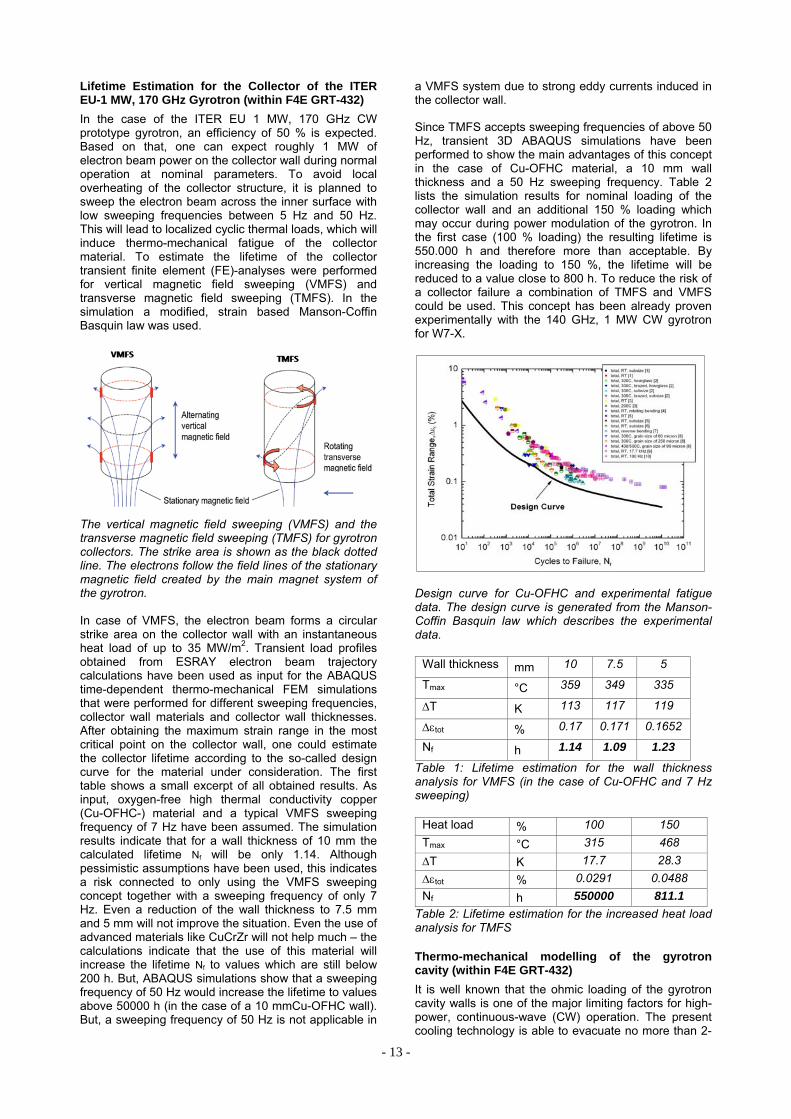
Lifetime Estimation for the Collector of the ITER EU-1 MW, 170 GHz Gyrotron (within F4E GRT-432)
In the case of the ITER EU 1 MW, 170 GHz CW prototype gyrotron, an efficiency of 50 % is expected. Based on that, one can expect roughly 1 MW of electron beam power on the collector wall during normal operation at nominal parameters. To avoid local overheating of the collector structure, it is planned to sweep the electron beam across the inner surface with low sweeping frequencies between 5 Hz and 50 Hz. This will lead to localized cyclic thermal loads, which will induce thermo-mechanical fatigue of the collector material. To estimate the lifetime of the collector transient finite element (FE)-analyses were performed for vertical magnetic field sweeping (VMFS) and transverse magnetic field sweeping (TMFS). In the simulation a modified, strain based Manson-Coffin Basquin law was used.
The vertical magnetic field sweeping (VMFS) and the transverse magnetic field sweeping (TMFS) for gyrotron collectors. The strike area is shown as the black dotted line. The electrons follow the field lines of the stationary magnetic field created by the main magnet system of the gyrotron. In case of VMFS, the electron beam forms a circular strike area on the collector wall with an instantaneous heat load of up to 35 MW/m2. Transient load profiles obtained from ESRAY electron beam trajectory calculations have been used as input for the ABAQUS time-dependent thermo-mechanical FEM simulations that were performed for different sweeping frequencies, collector wall materials and collector wall thicknesses. After obtaining the maximum strain range in the most critical point on the collector wall, one could estimate the collector lifetime according to the so-called design curve for the material under consideration. The first table shows a small excerpt of all obtained results. As input, oxygen-free high thermal conductivity copper (Cu-OFHC-) material and a typical VMFS sweeping frequency of 7 Hz have been assumed. The simulation results indicate that for a wall thickness of 10 mm the calculated lifetime Nf will be only 1.14. Although pessimistic assumptions have been used, this indicates a risk connected to only using the VMFS sweeping concept together with a sweeping frequency of only 7 Hz. Even a reduction of the wall thickness to 7.5 mm and 5 mm will not improve the situation. Even the use of advanced materials like CuCrZr will not help much – the calculations indicate that the use of this material will increase the lifetime Nf to values which are still below 200 h. But, ABAQUS simulations show that a sweeping frequency of 50 Hz would increase the lifetime to values above 50000 h (in the case of a 10 mmCu-OFHC wall). But, a sweeping frequency of 50 Hz is not applicable in
a VMFS system due to strong eddy currents induced in the collector wall.
Since TMFS accepts sweeping frequencies of above 50 Hz, transient 3D ABAQUS simulations have been performed to show the main advantages of this concept in the case of Cu-OFHC material, a 10 mm wall thickness and a 50 Hz sweeping frequency. Table 2 lists the simulation results for nominal loading of the collector wall and an additional 150 % loading which may occur during power modulation of the gyrotron. In the first case (100 % loading) the resulting lifetime is 550.000 h and therefore more than acceptable. By increasing the loading to 150 %, the lifetime will be reduced to a value close to 800 h. To reduce the risk of a collector failure a combination of TMFS and VMFS could be used. This concept has been already proven experimentally with the 140 GHz, 1 MW CW gyrotron for W7-X.
Design curve for Cu-OFHC and experimental fatigue data. The design curve is generated from the Manson-Coffin Basquin law which describes the experimental data.
Wall thickness mm 10 7.5 5
Tmax °C 359 349 335
T K 113 117 119
tot % 0.17 0.171 0.1652
Nf h 1.14 1.09 1.23
Table 1: Lifetime estimation for the wall thickness analysis for VMFS (in the case of Cu-OFHC and 7 Hz sweeping)
Heat load % 100 150
Tmax °C 315 468
T K 17.7 28.3
tot % 0.0291 0.0488
Nf h 550000 811.1
Table 2: Lifetime estimation for the increased heat load analysis for TMFS Thermo-mechanical modelling of the gyrotron cavity (within F4E GRT-432)
It is well known that the ohmic loading of the gyrotron cavity walls is one of the major limiting factors for high-power, continuous-wave (CW) operation. The present cooling technology is able to evacuate no more than 2-

- 14 -
3 kW/cm2 of heat flux on the cavity wall. The first result of the heat flux is the thermal expansion (deformation) of the cavity, which leads to a decrease in operating frequency (frequency shift) during the gyrotron pulse. Experimental measurements with the 140 GHz gyrotron series for W7-X show that this frequency shift is in the order of 200-300 MHz. Excessive heat flux can result in unacceptable frequency shifts in terms of reflections at the gyrotron window, which reflection coefficient is acceptably low in a small frequency range only. Moreover, the frequency specification itself may not be met. If excessive heating causes cavity expansion beyond the limit of plastic deformation, the device will be unusable.
It is understood that accurate modelling of the thermo-mechanical behaviour requires a multi-physics simulation. To this end, a numerical tool to simulate and analyse the thermal stresses in the gyrotron cavity was developed using the multi-physics, finite element software COMSOL. Input for the COMSOL simulations were delivered from the in-house code-package EURIDICE. Final target of the multi-physics tool has been to understand the behavior of the cavity, especially the deformations, and the consequences on the physical interactions generating the RF signal. The modelling focused on the 1 MW, 140 GHz gyrotron for W7-X. That is the gyrotron series for which the most experimental results on CW operation exist. However, even more important in future, will be the use of this tool in support of the forthcoming gyrotron developments for ITER and DEMO, for which the ohmic loading of the cavity wall is expected to be noticeably increased.
The developed model takes following into account: (i) An input heat flux with a specific profile, (ii) a complex coaxial cooling system (porous media and highly turbulent flows), and (iii) the mechanical interaction with surrounding components (fixed constraints and heat transfer). For such a tool, all the influential parameters in real conditions have to be considered. A major part of the work was devoted to the identification of these parameters. This included a preliminary study of the material properties, the architecture of the gyrotron, and the beam-wave interaction physics. The material used for the cavity is GlidCop® Al-15, which is a copper-based metal matrix composite (MMC) alloy containing a small amount of aluminium oxide ceramic particles. The relevant parameters are: Thermal conductivity [W/(m.K)], thermal expansion [K-1], specific heat [W/(kg.°C)], density [kg/m3], Young’s modulus [GPa], and electrical conductivity σ [S/m]. An additional parameter is the heat transfer coefficient h [W/(m2.K)] of the cooling system. After extensive research and discussions with specialists at TED, the proper range of the values for most of the parameters was identified. From simulations, it was seen that the most influential parameters are the heat transfer coefficient h and the electrical conductivity σ. Consequently, the investigations focused on improving the estimations for the values of these two parameters.
Typical results of the simulations are shown in the figures below. The model is iterative: First, the beam-wave interaction is calculated by EURIDICE for the cold, undeformed cavity and the hear flux on the wall is obtained. This heat flux is then introduced to COMSOL and the cavity deformation is calculated. Next, EURIDICE calculates the updated interaction and heat
flux in the deformed cavity. This is repeated until convergence of the results is reached. We note that both steady-state (estimating the final frequency shift) and time-dependent simulations (estimating the time constant for the deformation) were performed.
Cavity, cooling system, and heat flux profile.
Convergence of iterative scheme: Cavity profile (top) and heat flux profile (bottom) at each step.
Deformation and frequency shift as functions of time. Following the development of the model, comparisons with experimental results were initiated. This step pointed out some discrepancies, which indicate that the estimations of the model parameters, and in particular of h and σ, should be improved. This, together with enriching the experimental database with more measurements from dedicated experiments, is foreseen for the next research period. In conclusion, the developed tool, although in need of further calibration, is suitable for giving a much more detailed understanding of the thermo-mechanical behaviour of the cavity in operating conditions. The adaptability and simplicity of the model are very advantageous for studies dedicated to the design of forthcoming gyrotrons.
Beam-wave interaction modelling and code improvements (within F4E GRT-432)
Extensive, highly realistic multi-mode interaction simulations for the updated design of the 170 GHz, 1 MW cylindrical gyrotron for ITER have been

- 15 -
performed (also in collaboration with HELLAS). The following issues were addressed: Validation of the final gun design with emitter thickness of 5 mm, validation of the final cavity geometry with 19.24 mm outer radius, identification of appropriate operating point for highly efficient 1 MW short-pulse operation, and parametric studies for operation with electron beam of reduced quality. The simulations of the cavity and the non-linear uptaper took into account the start-up and beam neutralisation phase, as well as a realistic magnetic field profile and the spread in electron velocity. The final design was validated. An appropriate operating point for short pulse was also verified. The parameter studies at reduced beam quality (low pitch factor- high velocity spread) showed that the design is robust. Typical simulation results for the output power and the efficiency in the nominal CW operation scenario are shown in the following graphs:
Typical simulation results of mode sequence and output power (top) and voltage, Ohmic wall loading and efficiency dependence (bottom) during start-up.
Numerical studies on parasitic dynamic After-Cavity Interaction (ACI) generated a multitude of results and code upgrades in the last 3 years. To clarify the situation, a direct comparison between different codes and approaches has been performed for the first time, encompassing all the known (in simulation) ACI cases, namely (i) the 140 GHz, 1 MW gyrotron for W7-X, (ii) the step-tunable gyrotron, (iii) the 170 GHz, 1 MW gyrotron design for ITER with the ASG magnetic field, and (iv) the 118 GHz, 0.5 MW gyrotron for TCV, EPFL, Switzerland with uniform magnetic field. The following codes and approaches were compared:
1. SELFT and EURIDICE (trajectory approach) 2. EURIDICE quasi-PIC (filled-cavity approach) 3. GyroDyne (1-D PIC approach)
The result is that ACI appears in all four cases using the trajectory approach, whereas it clearly appears only in case (iv) with the PIC approach. Taking into account that the PIC approaches are more valid for ACI modelling, we could conclude that the trajectory codes exaggerate on their results on ACI and there is a considerable possibility that dynamic ACI can sometimes be an artefact of the trajectory approach. However, in contrast to the trajectory codes, EURIDICE quasi-PIC and GyroDyne are newly developed codes and their verification cannot be considered complete. At the same time, the ACI cases studied up to now cannot be investigated with commercial full-wave PIC codes because of the extreme computational resources needed due to the high-order modes involved. Thus, to verify the newly developed codes and their results on ACI, an artificial scaled-down ACI case with the low-order TE03 mode at 140 GHz in an appropriate cavity & uptaper was found and simulated with CST Studio Suite. The studies, done in collaboration with HELLAS, are ongoing, but up to now no ACI is predicted. More definitive conclusions are expected in the near future, after additional simulations and code upgrades towards the PIC approach.
For dynamic ACI studies, as well as for studies of gyrotron operation for which sidebands around the operating frequency appear, the usual single-frequency boundary condition for the RF field profile is not appropriate. It introduces additional artificial numerical reflections in the simulation. A more suitable, broadband, totally adsorbing boundary condition is available in EURIDICE. However, it requires a very short simulation time-step to work properly. Significant efforts were made on improving this matched condition and also, going a step further, on formulating a more general boundary condition for which a frequency-dependent reflection can be externally defined. By doing this, the reflection from the components following the gyrotron cavity can be modelled more realistically. The reasoning and first results of the extended model are described below.
The boundary condition for a single mode in frequency domain can be formulated as
,
, for at boundaries,
where , is the envelope for the field, 1 at the emitter side and 1 at the launcher side, is the normalised wave impedance, which can be expanded in Taylor series
∑ ,
Γ is the frequency dependent reflection coefficient, and is the axial wave number
cut
, which can be written as
cut cut⋇ .
Here, is the mode carrier frequency, cut is the cut-off frequency, is the velocity of light, √ stands for the square root with a zero or negative imaginary part, and is the Taylor series

- 16 -
∑ ∙ ∙ ⋯
! cut
The existing matched broadband boundary condition is improved with the introduction of the Taylor series. The two series can be merged into one polynomial and can be handled together.
The next figures demonstrate two test cases for a boundary configuration relevant to the W7-X gyrotron (cut-off frequency 130 GHz, carrier frequency at 140 GHz). In both cases a Gaussian pulse from 120 GHz to 160 GHz is used as a source term. The first figure shows the improved matched boundary condition. In the second figure an externally defined reflection is taken, which is assumed to be 0 at 150 GHz and 5% at 140 GHz. It can be observed, that the simulated reflection follows the theoretical (dashed) curve inside the defined frequency range.
Simulated reflection coefficient versus frequency for imposed reflection at the boundary equal to zero (bottom) and for linear dependence (top). Note: the physical region is above 130 GHz (cut-off).
Emitter surface roughness model for gyrotron calculation (within F4E GRT-432)
The velocity spread of the electron beam from the Magnetic Injection Gun (MIG) is assumed to be one of the most important factors that decreases the efficiency of a gyrotron and facilitates mode selection in the cavity. The microstructures on the emitter surface which will decrease the uniformity of the local electric field on the emitter surface is one of the most important reason for that velocity spread. In order to investigate the effect a new surface roughness model has been build. The surface roughness is modeled with several kinds of microstructures in a modified version of the electrostatic beam optics code ESRAY, as is shown in the figure above. The new emission model can reproduce the effect of the microstructure even under the influence of a tilted magnetic field, as shown in the next figure.
The six microstructures used in the ESRAY
Comparison of the velocity spread caused by the real and virtual bump
Calculations done with the gyrotron interaction code EURIDICE show that in the gyrotron the transverse velocity spread of the electron beam and the gyrotron efficiency are affected by the microstructure, as is shown in the figure below.
Relation between microstructure size, final distribution (a), and gyrotron efficiency η (b) in the case of the 1 MW, 170 GHz EU gyrotron for ITER
0
0.2
0.4
0.6
0.8
1
110 120 130 140 150 160 170 180
(art
ifici
al)
refle
ctio
n co
effic
ient
frequency / GHz
simulatedexpected
0
0.2
0.4
0.6
0.8
1
110 120 130 140 150 160 170 180
sim
ula
ted
re
flect
ion
co
eff
icie
nt
frequency / GHz
matched boundary
0.32 0.34 0.36 0.38 0.40 0.42 0.44 0.46 0.480.0
0.2
0.4
0.6
0.8
1.0
Nor
ma
lize
d P
roba
bilit
y D
ens
ity
r0=0 m
r0=1 m
r0=3 m
r0=5 m
r0=7 m
r0=10 m
0 1 2 3 4 5 6 7 8 9 100
1
2
3
4
5
6
Microstructure size (m)
34.0
34.5
35.0
35.5
36.0
36.5
37.0
37.5
38.0
38.5

- 17 -
From the figure above one can see that with the increase of the microstructure size from 0 µm to 10 µm the perpendicular velocity spread δβ increases from 0.86% to 5.3% and the gyrotron efficiency decreases from 38.2 % to 34.5%, respectively. Multimode calculations show that the working mode will start later due to the increase of the microstructure size.
Emission uniformity test device
The emission uniformity of the emitter is another factor which will increase the velocity spread of the electron beam of the MIG. A new emission uniformity test device has been developed at KIT and is in use since 2013. In the emission uniformity test device the distance between the anode and the cathode is designed to be 2 mm, so that it can work at a lower voltage with the same electric field strength compared to the gyrotron.
Emission test device The temperature information of the emitter is measured by an infrared camera which is put in front of an infrared window, as is shown in the figure above (a). The emitter is heated up to its nominal temperature about 900ºC, as is shown in the figure above (b). In order to receive the information about the angular temperature and emission uniformity the emitter is designed to be rotable, as is shown in the figure above (c). Relative temperature distribution along the whole emitter surface is shown in the next figure (middle part of the picture). The figure shows significant temperature differences. One possible reason for that temperature increase on some places of the emitter is that the emissivity of those areas is different from that of the rest.
Relative temperature distribution on the emitter surface (middle part of the picture)
The next step is to get the absolute temperature on the emitter surface with the correction of a pyrometer and test of the angular emission uniformity.
Quasi-optical mode converter and Matching Optics Unit for TE32,9-mode gyrotron (within F4E GRT-432)
KIT is leading the theoretical design of mirror-line type launchers. As the surface contours of mirror-line launchers are more complicated compared to helically deformed launchers, it is very important to investigate a tolerance analysis of mirror-line launchers. A mirror-line
launcher has been designed for the TE32,9-mode gyrotron developed for the ITER tokamak. The tolerance of the mirror-line launcher has been investigated. An important result is that if deviations of the surface of the real device and the design are less than 10 micrometer, the stray radiation from the launcher will be smaller than 3%.
A Matching Optics Unit (MOU) has been designed for the TE32,9-mode ITER gyrotron in order to match the free space Gaussian output beam of the gyrotron to the corrugated HE11 waveguide transmission line. The structure of the MOU vessel has been designed according to the technical requirements. The beam-shaping mirrors have been optimized to provide a conversion efficiency of 95.57% for the RF beam to the HE11 mode which can satisfy the requirement of the conversion efficiency to be larger than 95%. The field distribution of the RF beam radiated from the MOU is shown in the figure below. It has been found that the current design of the MOU vessel is not big enough for the possible displacement of the gyrotron mirrors.
Field distribution at the output of MOU.
A parallelized version of TWLDO code has been developed which reduces the CPU run time by 20%.
A computer code for the vector analysis of RF fields in launchers is under development at KIT. Curved triangle meshes will be used to match the circular waveguide wall surface. A formula for the calculation of the field at the neighbor mesh points has been derived.
In order to improve the conversion efficiency of cavity modes to a Gaussian distribution, the combination of helically deformed launcher and mirror-line launcher has been tested. However, the simulation results show no enhancement of the conversion efficiency.
Activities towards DEMO gyrotrons
First feasibility studies towards the physical design for a coaxial DEMO-compatible gyrotron (CW, design frequency approx. 240 GHz, high efficiency, power significantly above 1 MW, possibility of step-tuneability (~2 GHz) and of multi-frequency operation (~35 GHz)) have been undertaken. It has been investigated which area in the design parameter space is physically and technically reachable. For this purpose, a new interactive design code has been written based on relevant formulas and data.
A novel mode-selection strategy for coaxial-cavity gyrotrons operating at high-order modes (eigenvalue χ~150) has been developed. The new strategy focuses on mode restrictions imposed by the assumed quasi-optical launcher and single-disk window of the gyrotron
Field distribution, linear
x/mm
y/m
m
Phase pattern, linear
x/mm y/
mm

- 18 -
rather than on spectral considerations, since the mode spectrum in such gyrotron resonators depends only little on the actual main mode. This strategy has also been integrated into the new code.
The results have been verified and used for finer studies using CAVITY, the main in-house gyrotron design package at IHM. Simultaneously, the CAVITY package was tested for accuracy and limitations during high-order mode and high frequency calculations. The mode TE49,29, theoretically capable of 2 MW output power, has been found appropriate for a gyrotron meeting the aforementioned criteria. A typical startup scenario involving 52 modes is shown in the next figure. Design optimization of the resonator has been started. The operation regime has been found robust against azimuthal instabilities of the main mode. For further verification, quasi-particle-in-cell (quasi-PIC) simulat-ions using the EURIDICE code are planned.
First investigations on the associated magnetron injection gun (MIG), the design of which is expected to be the most severe limitation on the output power of the gyrotron, and on the launcher have been undertaken. Detailed investigations will be the focus of the studies during the next year.
Startup scenario considering the design mode TE49,29 and 51 competing modes, output power in kW (logarithmic scale) vs. time in ns. Development of a low power gyrotron for the test of a new emitter concept
A 10kW/28GHz gyrotron has been designed and manufactured to evaluate the use of controlled porosity reservoir (CPR) emitters for gyrotron applications. CPR cathodes allow operation with higher current density (up to 50 A/cm2) and provide much longer lifetime (~100000 h) compared to conventional emitter materials (LaB6, conventional dispenser cathodes, etc.). In addition, the azimuthally segmented emitter ring provides the possibility to generate controlled non-uniform electron beams in order to study the effect of non-uniform emission on the gyrotron output power and efficiency.
All parts for a 10kW/28GHz gyrotron with conventional M-type emitter have been manufactured and assembled. The designed drawing and a photography of the 10kW/28GHz gyrotron are shown in the figure below. For verification of the gyrotron parameters first experiments will be performed with a conventional M-type emitter. Cathode with this emitter is shown in the second figure below, a test of the cathode has been performed in a vacuum bell jar. There the emitter has been heated up to nominal temperature and showed
uniform temperature distribution along the azimuth as well as good thermal isolation of the emitter from its adjacent parts like cathode nose and back focus electrode.
The manufacturing of the gyrotron test stand is almost finished, including water cooling, data acquisition, interlock and power supply systems. Start of experimental investigation is planned for first quarter of 2014. The segmented emitter is in the final manufacturing phase and has to be assembled at the beginning of 2014. The design drawing for the segmented cathode and a photography of a single manufactured segment are shown in the third figure below.
Design drawing (left) and assembled 10kW/28GHz gyrotron (right).
Design drawing of the conventional emitter (left), manufactured cathode (middle) and heated emitter (right).
Design drawing of the segmented emitter (top left), manufactured segment (top middle and bottom right).

- 19 -
– ITER ECRF Advanced Source Development –
Coaxial-cavity Gyrotron
The development of a 2 MW 170 GHz short-pulse coaxial-cavity gyrotron prototype is in progress at KIT. Coaxial-cavity gyrotrons (with inner rod) offer advantages in comparison to conventional-cavity gyrotrons, namely reduced voltage depression and mode competition, resulting in higher output powers and operating frequencies. The coaxial arrangement has a potential to provide higher RF output power per unit, compared with conventional hollow-cavity gyrotrons, for reduced cost and space requirements. Gyrotrons for future fusion devices, operating at multi-megawatt power levels and frequencies above 200 GHz, most probably will be of coaxial-cavity type. Since the coaxial-cavity technology has the potential of considerably higher output power KIT is continuously pushing forward this development, as very attractive alternative solution for the ECRH systems of future fusion experimental reactors and demonstration power plants (particularly DEMO).
Preliminary experimental results
In first experiments, stable operation of the KIT short-pulse coaxial-cavity prototype was limited to a cathode voltage below 80 kV and a beam current of maximum 60 A. Instabilities limited the pulse length to below 0.5 ms. Nevertheless, an RF output power of 1.9 MW with an overall efficiency of 28% (without depressed collector) has been obtained in single TE34,19-mode operation at 170 GHz. The following parasitic effects limited the gyrotron operation:
1. Electron beam instabilities: The clearance between the electron beam and the anode wall has been ~0.2 mm only, which is not in line with the 2.3 mm which has been obtained from numerical calculations. The clearance has been observed by measuring the body current at the halo shield. The significant increase of the beam thickness confirmed an existence of an electron halo consisting of electrons trapped between the cathode and the magnetic mirror. It is assumed that those trapped electrons were also responsible for a rise of body/coaxial-insert currents observed during the gyrotron operation.
2. Parasitic oscillations: Low frequency (LF) oscillations at two different frequencies, 112 MHz and 453 MHz, were found for beam currents Ib > 60 A. The observed spectrum of LF-parasites was depending on the gyrotron operating parameters. But, surprisingly, no dependence of the frequency values on the accelerating voltage were observed. The excitation of another type of unwanted oscillations in the higher GHz-range is usually related to the beamtunnel region. In order to suppress such oscillations, the patented KIT-standard design of the beam tunnel (absorption ceramic-copper rings “sandwich” structure) was equipped with additional slots on the copper rings. Recently, a different concept of the beam tunnel (fully out of absorbing semiconductor ceramics SiC) has been manufactured and successfully tested. In the experiments with that new ceramic beam tunnel no parasitic oscillations have been found.
Theoretical investigations on the electron beam instabilities
The beam halo current as observed in the recent experiment could have been a reason for the reduction of the gyrotron performance. The beam halo (travelling electrons outside the regular electron beam) is thought to be caused by electrons trapped between the cathode and the magnetic mirror. In particular, secondary electrons emitted from the cathode surface near the emitter are assumed to contribute significantly to the halo current. Thus, the properties of electrons emitted from that surfaces may be of big importance for the halo generation. Therefore, the trajectories of electrons emitted from the cathode surface around the emitter have been calculated. The calculations have been done for electrons leaving the cathode surface with zero velocity. The results shown in the figure below and the second figure below confirm the existence of magnetically trapped electrons between the electron gun and the cavity region. The next figure shows the maximum value of the pitch angle of the electrons as obtained for the nominal operating gyrotron parameters (UC = 90 kV, Ib = 75 A).
Pitch angle at the cavity of electrons emitted from different positions of the cathode surface.
Calculated trajectories of electrons emitted from the cathode surface. Magnetically trapped electrons are indicated in red.
The parameter s represents the emitted position of the electrons along the cathode surface, starting from the inner side of the cathode nose (s < 0.3), passing through the emitter region (0.3 < s < 0.4) and ending at the rear part of the cathode (0.4 < s < 0.6). As shown in the figure above, the electrons emitted from the emitter surface have a maximum pitch angle ~ 1.5, a value far away from being trapped. On the other hand,

- 20 -
electrons emitted above the emitter ring (s > 0.45) and around the cathode nose (s ~ 0.24) have very high pitch angle values. Electrons emitted from these areas could be trapped with very high probability. The trajectories of the electrons emitted along the cathode surface are presented in the figure above. The yellow lines represent not magnetically trapped electron trajectories, the blue lines show the trajectories of electrons emitted from the emitter ring. The red lines define the electron trajectories that are magnetically trapped. The number of the trapped electrons could increase very rapidly (catastrophic event) if the emitted electrons are secondary electrons with a non-zero starting velocity. A secondary electron emission can be caused due to the bombardment of the cathode by the already existing trapped electrons. From the recent experiments the beam halo current can be estimated to be nearly as high as the beam current, which results in a significantly increased space charge level. A high level of trapped electrons might explain the rise of the currents to the body/coaxial insert and the discharges/arcing observed inside the tube during the experiments resulting in a reduction of the stable operation of the gyrotron.
Surface damages observed on of the anode (left) and coaxial insert (right) created due to the activity of trapped electrons.
Further inspection of the gyrotron components confirmed the existence of trapped electrons. In the region of anode (very close to the halo shield) and in the middle part of the coaxial insert, characteristic surface damages and melted spots have been found (see the figure on the left side below)
Results of the experimental investigation on LF- parasitic oscillations
As mentioned before, two different parasitic LF-oscillations in the MHz range (at 112 MHz and 453 MHz) were found in the experiments. The fact, that the frequency of both oscillations was totally independent on the accelerating voltage, indicated an unwanted resonant behavior of the geometrical structure. In that case, the oscillation is generated due to the interaction of the pre-bunched electron beam with the existing field excited in the resonant regions of the gyrotron construction. In order to find the spectrum of resonances of the gyrotron construction, the tube has been modeled and analyzed using the CST Microwave Studio. The simulation results show that the first oscillation at 112 MHz is related to the resonance of the coaxial insert. However, because of the relatively low intensity of the resonating field the oscillation has been classified as uncritical for the stable gyrotron operation and therefore was not investigated in particular. Another, much stronger resonance was found at 453.4 MHz in the mirror-box and collector section of the gyrotron. The theoretically predicted frequency was in a very good agreement with the frequency of the strong
LF-oscillation obtained experimentally. The calculated distribution of the longitudinal component of the resonant electric field is presented in the next figure. Numerical simulations at ~453 MHz confirm that the travelling electrons can interact with the field which is excited in the mirror-box and the collector region. As observed experimentally, the amplitude of the resonant field was constant in time, which indicated a closed feedback loop in the interaction between the field and the travelling electrons. An inspection of the gyrotron assembly die show a problem with the RF isolation of the internal gyrotron connector: the shielding of the feed-through connector placed at the mirror-box wall connected via coaxial cable to the cavity probe was not correctly installed (see second figure on the next side). Due to missing RF-isolation a part of the resonating field was coupled back from the mirror-box directly into the gyrotron cavity. It resulted in an additional modulation of the electron velocity in the cavity region. In effect the bunched electrons, passing through the mirror-box region, interacted again with the resonating field and led to increase of the intensity of parasitic oscillation.
Calculated distribution of the resonating field at 453.4 MHz (mirror-box and collector region)
Excitation mechanism of the parasitic LF-oscillation at 453 MHz.

- 21 -
Due to the improved shielding the problem with the previously observed limitations in the gyrotron operation has been solved. It results finally in a much better performance of the gyrotron.
Stable gyrotron operation – final results
The removal of the LF-oscillations resulted in a significantly more stable gyrotron operation up to the nominal operating parameters (UC < 90 kV and Ib < 75 A). Finally, close to the nominal operating point an output power of 2.0 MW at an efficiency of 28% (without depressed collector) has been successfully achieved. The dependence of the generated RF output power on the accelerating voltage at the beam current of 75 A is shown in the next figure. Additionally, in order to increase the generated output power, the magnetic field in the gyrotron cavity has been slightly risen up. It allowed shifting the excitation region of the nominal mode to ~92 kV. In parallel the electron beam current has been set to be 84 A. At these conditions a new world record in the generated RF output power (per single tube), namely 2.3 MW at 30% efficiency, has been set.
Measured RF output power as a function of accelerating voltage (obtained at Bcav = 6.87 T and Ib ~ 75 A)
Furthermore, in the very preliminary gyrotron experiments with depressed collector an output power of 1.9 MW at an efficiency of ~43% has been demonstrated. The optimization of the operating point with the depressed collector is planned for begin of 2014.
Alternative method for the electron beam alignment with respect to the mechanical axis of the gyrotron
The position of the electron beam axis relative to the axis of the cavity can be obtained, under operating conditions with high accuracy, by measuring of the region of single mode oscillation in dependence of a transverse shift of the electron beam. The transverse displacement of the electron beam around the position of the cavity is obtained by applying independently a current to two sets of dipole coils of the OI SC-magnet. Doing that, the electron beam can be displaced independently in two radial directions (x- and y-direction) which are perpendicular to each other. In order to determine the area of single mode oscillation in the xy-plane, the electron beam is radially displaced and the oscillating mode is observed. In general, the boundary of single mode oscillation in dependence of
the shift is very well defined. It has been detected with a frequency filter bank together with a frequency measurements device. Based on the measured points in the xy-plane an oscillating range in form of a circle is found (next figure). From the center of the circle the information about the displacement of the electron beam relative to the cavity can be obtained.
Firstly, the position of the electron beam relative to the cavity has been determined by measuring the area of the single-mode operation. Then, the solenoid coils of the SC-magnet, respectively, the axial B-field B(z) has been shifted radially. The related displacement of the electron beam has been determined from the single-mode oscillation area. After doing that, the measured shift of the electron beam has been compared with the values expected from the mechanical parameters of the SC-magnet, and, in addition, it has been compared with the values obtained from the position of the electron beam relative to the coaxial insert.
The next table shows an example of the results obtained from the measurement of the single-mode operating area. The results are consistent with the positions of the eelectron beam obtained from the measurements of the electron beam relative to the insert and from the mechanical data. The experiments have also shown that it is not necessary to use the nominal 170 GHz TE34,19-mode for the definition of the area of mode operation. The measurements with the TE33,19-mode (next neighbour of the nominal mode) have provided identical results compared to the measurements using the TE34,19-mode.
Example: Oscillating range for the TE33,19, 167.9 GHz; Uc = 72 kV; Ib = 24 A.
action e-beam to center of cavity
e-beam to the insert
shift of the electron beam obtained from: [a] insert
position, [b] oscillating area,[c] mechanical shift
[a] [b] [c]
Insert aligned
____ 0.12 / 0.07
____ ____ ____
SC-coils shift
~0.15 0.26 / 0.16
0.12 / -0.13
0.0 / -0.2
-0.03 / -0.2*
-0.07 / -0.17 **
0 /-0.15
Tab. 1. Measurement example; * values estimated from the shift of the e-beam relative to the insert. ** values estimated from the mechanical shift of the displacement.

- 22 -
– ECR Heating and Current Drive: Step-Tunable Gyrotron Development -
Energy spectra of spent electron beam recovered from x-ray spectrometry.
In 2013, the proof-of-the-principle testing and facilitation of the x-ray based technique of definition of energy distributions in electron beams in the conditions of high-power gyrotrons were performed. In previous sessions (October 2012) the problems with excessive photon flux density was determined, deteriorating the performance of x-ray spectrometer. It was decided to solve the problem by the use of Compton scattering in the materials.
The schematics of layout are shown in the next figure. The spectrometer was placed at the collector and protected with a thick-walled pipe from the direct x-rays generated by the electron beam. It collected only photons scattered in the 2 mm thick Al window irradiated with the direct x-rays. For the energy band of interest (20-100 keV) and scattering angles below 30 degrees the relative energy loss (due to inelastic scattering) cannot exceed 2%. The energy distribution can be corrected to take this into account.
Experimental layout.
20 30 40 50 60 70 80 90 1000
10
20
Kramers' law + attenuation in 2 mm Al
measured spectrum
Kramers' law
38kV62kV
U=87kV
pho
ton
cou
nts,
a.u
.
photon energy, keV
Bremsstrahlung spectra for low current (without RF).
To calibrate the data acquisition system and compare experimental data with theoretical predictions, we measured bremsstrahlung spectra in low-current regimes of the gyrotron without interaction in the cavity. This should ensure that all electrons have the same energy corresponding to the gun voltage U. The measured bremsstrahlung spectra demonstrated a very good agreement with predictions of the basic theory: Kramers’ law and exponential attenuation of low-energy photons in the aluminum window (see figure above).
If we divide the bremsstrahlung spectra to the corresponding Kramer’s law, the fit may be interpreted as full attenuation coefficient for photons of energy E on their way to the spectrometer. Therefore, this ratio must be independent on the parameters of the electron beam, which is demonstrated in the next figure.
The measurements of the spectra were performed for different aperture of the spectrometer in order to check the independence of the energy spectra on the photon flux. It is shown that by a higher spectrometer input flux (400 m collimator) it gives a lower number of photons in the high-energy part of the spectrum. For instance in the figure on the right side one can find a plot similar to the figure below where the normalized spectra were divided by the Cramer’s distribution. In this case, no saturation above 50 keV takes place and discrimination of photon signal with higher energy occurs.
The observed errors may originate from incorrect performance of so-called “Baseline restoration system” (BLR).
The appearance of a baseline shift leads to incorrect definition of these energies. Even though the BLR system of the spectrometer was “ON” during our experiments, it may be inefficient (or insufficiently efficient) when the photon flux represents a series of ms-length pulses with high intensity separated by long (a few seconds) intervals. In the regimes when the flux intensity was the highest (large collimator hole, high gyrotron gun voltage), the baseline of the spectrometer measurement circuit might had shifted during a gyrotron pulse. As a result, photon energies were determined correctly only at the beginning of each gyrotron pulse (and gave us correct high-energy cut-offs in the measured spectra), while most part of photons were ascribed to lower energies in comparison to their correct values.
20 30 40 50 60 70 800,0
0,5
1,0
U=87 kV 62 kV 38 kV sigmoidal
approximation
N/(
eU/E
-1)
E, keV
Ratio of X-ray spectra for low-current regimes measured with 200 m collimator, divided by the Kramers’ factor NKram(E)=Const(eU/E-1).

- 23 -
During the reported experimental session, we measured x-ray bremsstrahlung spectra for 8 regimes of the gyrotron. The regimes were different in generated mm-wave power, gun voltage, beam current and magnetic compression. For all these regimes the electron energy distributions were reconstructed. All distributions are wide and include electrons with energies between 32.5-35 keV and 80-90 keV (the latter corresponds to the gun voltage). In the most cases a correlation with the output power value (though not very pronounced) may be noted: the distribution for the regime with the lowest mm-wave output obviously has the highest energy “cut-off”.
The discrepancy between the measured value of efficiency and obtained from reconstructed electronic spectra may achieve up to 15-20 percentage points (in the best case). The disagreement between experimental values of RF efficiency of the gyrotron and electronic efficiency calculated from experimental data originates from incorrect spectrometer performance in pulsed regime with high peak x-ray flux as noted above. The spectrum which was measured with the 400 m collimator demonstrates the highest discrepancy predicting a efficiency of 0.6, while the largest value of RF efficiency measured experimentally is 0.27. Usually the “dead time” parameter of spectrometer substantially exceeds the 0.5-0.6 value which was set to ensure correct performance of the spectrometer. The smallest difference between values of calculated electron efficiency and RF efficiency corresponds to measurement which were performed at low beam current and short “dead time” value.
20 30 40 50 60 70 80 900.0
0.2
0.4
0.6
0.8
1.0
N /
(eU
/E-1
)
E, keV
U=95 kV 87 kv 75 kV 62 kV 50 kV 38.6 kV approxi-
mation
X-ray spectra for low-current regimes with 400 m x-ray collimator.
Numerical study of the influence of the axial electron beam misalignment effect on the performance of the 1MW gyrotron and comparison with experiment.
In 2012 the results of numerical simulation using the recently developed self-consistent multimode non-stationary code “Gyrodyne” were reported. In both cases, experimental and numerical simulation predict a similar type of dependence – quadratic decay of the output power with the shifting of the beam axis relative the center of the resonator (see next figure).
The properties of the beam used in the simulation are obtained from an ESRAY static self-consistent code. From ESRAY calculation it follows that the pitch factor of the electron beam is more than 1.4, the electron beam radius is 7.9 mm. The spread of the pitch factor is taken to 20%. These simulations show that the output power is more than 1300 kW, while in the experiment the measured value is around 1000 kW.
In addition, the experimentally measured curve demonstrate less steep decay in comparion to numerical simulation, and both curves cross at 0.9 mm beam shift.
It is also interesting to note that in the measurement the excitation of the main mode is observed at relatively large beam misalignments, up to 1.1 mm, while in the numerical simulation at this beam shifting the counter rotating mode is excited with power less than 200 kW (in experiment such a power would be even less at the output due to counter rotation of the mode and a mismatch with the quasi optical system).
Numerical simulation and measurement of the output power as the function of beam shifting. In both cases, in the measurement and in the numerical simulation with large beam shifting (> 0.6 mm) with the increase of the beam energy the excitation of the main mode is terminated by the appearance of the spurious TE19,9 mode instead of TE21,8- mode as it takes place in the normal, aligned condition. The result can be interpreted considering the averaged structural factor corresponding to the coupling of the beam and the mode.
Since the discrepancy between the measurement and numerical simulation can always occur because the real electron beam properties can be different from the assumed ones, it was interesting to try to perform the numerical simulation taking imperfections of the beam into account. Deterioration of the energy spread of the electron beam, but remaining the coupling of the beam and the mode, would not change the relative sensitivity of the output power in dependence of the beam axial misalignment, while reducing overall performance. Therefore, the thickness of the beam was varied. In the figure below the numerical simulation performed for a number of “thick” electron beams presented by quasi particles with an introduced spread of guiding centers is shown. The current density of the electron beam within the cross section of thick beam is kept constant.

- 24 -
etter quantitative agreement is obtained for thicker electron beams. The results suggest that the performance of the gyrotron can be improved by improving the quality of the electron beam inside the cavity (e.g. “thickness” and shape of electron beam).
Numerical simulation for electron beams with different thickness. Detailed diagnosis of undesired transient effects
The continuous development of more elaborate means for gyrotron spectrum analysis has yielded in a sophisticated measurement system which allows the time-dependent investigation of the spectral mode evolution over time. Apart from a high dynamic range of 50-60 dB, frequency unambiguity is a key feature of the measurement system.
As an example, in the next figure a measurement containing highly transient effects is depicted. It shows the direct observation of mode competition and switching during an external arc, which occurred during the operation of a W7-X gyrotron close to the edge of the stability area of the nominal mode TE28,8.
Along the time axis (bottom to top), first the slow starting of oscillations over the high voltage power supply (HVPS) parameter ramp (right part of figure) of the cathode voltage Vc and the beam current Ib is visible. After the HVPS reaching flat-top, stable operation of the nominal cavity mode at 140.25 GHz is established.
Around pulse time 300µs, a destabilization of the mode occurs, which is followed by the start of a competing cavity mode at 137.45 GHz. The prolonged competition between the two modes is directly visible in the spectrogram through strong symmetrical modulation patterns. After ~50 µs of mode competition, the nominal cavity mode is suppressed, which allows the competitor to oscillate undisturbed till pulse end.
During the measurement, an arc at the gyrotron’s microwave output window was detected, which is very likely the cause of the perturbations: being essentially a plasma, an arc at the window can absorb, but also reflect significant amounts of power back into the tube. This can disturb the oscillation (load pull effect) and hence lead to changes in behaviour. Since such events are to be avoided because of their damage potential, detailed information on their properties and behaviour is scarce and valuable.The availability of this data enables more closer linkage between experiments and general gyrotron simulation, and after parameter studies more information on the arcing phenomena can be gathered by comparison with the measurement data.
Excerpts from such an undertaking, which is still in progress, are shown in the second figure on the next side. The fundamental effect of the arc with respect to the gyrotron interaction lies in the back-reflected power. The intermediate result of a parameter study of complex reflection factors at the gyrotron output is shown. While for many reflection factors stable operation at relatively constant power is maintained, in a significant area of the reflection factor plane stationary oscillations (auto-modulation) is observed.
In a small convex area, the reflection causes a mode switch to the azimuthal neighbour mode TE27,8 at
137.45 GHz after a short interval of auto-modulation, matching the effects documented in the next figure surprisingly well. Such investigations still are subject to many degrees of freedom and physical uncertainties; however this example demonstrates the new opportunities not only for basic gyrotron physics investigation, but also for the assessment and benchmarking of the available simulation tools.
Excerpt from spectral measurement during RF window arc. The measurement system allows the detailed investigation of the mode spectrum and its evolution over time with a high dynamic range and microsecond time resolution.

- 25 -
– Launcher Handling and Testing facility
LHT –
The purpose of the Launcher Handling and Testing facility for the ITER ECRH Upper Launcher is to provide a prototype test bed for the structural launcher components. The facility can be used for prototype testing but also on a longer term perspective for component acceptance tests in the procurement phase. In principle it can be also adapted to gyrotron bake out conditioning. It provides a water circuit with a large range of temperatures and pressures up to ITER bake out (240°C at 4.4MPa) and the ability to apply fast thermal transients. In the past year the facility was extended significantly in the frame of a BMBF project with a large vacuum vessel, control system and an attached mass spectrometer for high resolution measurements of outgassing properties of tested components depending on their manufacturing route. In its current state the facility is ready for the foreseen Prototyping and Testing contracts in the frame of the ITER ECRH Upper Launcher development program with F4E.
Launcher Handling Test Facility
Involved Staff:
KIT/IHM
K. Baumann Dr. B. Bazylev Dr. D. D‘Andrea Dr. G. Dammertz J. Franck M. Fuchs Dr. G. Gantenbein Dr. H. Hunger Dr. Yu. Igitkhanov Dr. S. Illy Prof. J. Jelonnek Dr. J. Jin Th. Kobarg Dr. I. Landman R. Lang W. Leonhardt M. Losert A. Malygin D. Mellein A. Meier (KIT, IAM-AWP) S. Miksch Dr. I. Pagonakis A. Papenfuß K. Parth Dr. S. Peschanyi Dr. B. Piosczyk Dr. A. Roy Choudhury Dr. T. Rzesnicki Dr. A. Samartsev A. Schlaich Dr. Theo A. Scherer (KIT, IAM-AWP) A. Schlaich (KIT CS) M. Schmid W. Spiess Dr. D. Strauss (KIT, IAW-AWP) J. Szczesny Prof. M. Thumm J. Weggen J. Zhang
IPF (University of Stuttgart) Dr. W. Kasparek C. Lechte
R. Munk
Dr. B. Plaum H. Röhlinger F. Remppel P. Salzmann K.H. Schlüter S. Wolf
A. Zeitler
(Diploma/Master students) Z. Popovic P. Rohmann D. Tretiak IPP (Greifswald/Garching) B. Berndt Dr. H. Braune Dr. V. Erckmann (PMW) F. Hollmann L. Jonitz Dr. H. Laqua G. Michel F. Noke M. Preynas F. Purps T. Schulz T. Stange P. Uhren M. Weißgerber
right: simulated Rieke diagram Left: sample mode evolutions from simulation parameter study

- 26 -
(Diploma/Master students) M. Cordova F. Kahl V. Kamra M. Hruszowiecz V. Ramopoulos S. Ruess C. Wu
HGF Program: ENERGY
Renewable Energies (EE)
– Conditioning of Biomass by Pulsed Power Techniques –
Pulsed electric field (PEF) treatment has been proven to be an appropriate technique for releasing intracellular components from microalgae. Compared to conventional mechanical cell disruption techniqes, the energy demand for PEF treatment is low and efficiency does not decrease at high microalgae biomass concentrations in the suspension to be treated.
For pilot-scale PEF processing several kilograms of fresh microalgae biomass are required which will be produced by a 1000 l photobioreactor to be installed at the former greenhouse area of IHM. At current state basement and auxillaries are completed.
Growth stimulation by nsPEF exposure has shown to increase biomass yield of Chlorella vulgaris by 10 % without admixing additives to the culture medium. Phytohormon admixture did not show synergetic behavior as it was obtained with clamydomonas reinhardtii the year before.
A new effect of subsequent pulse exposure on single cells’ plasma membranes could be identified by patch-clamp technique. The conductance of the recovered membrane increases with the number of pulse exposures. This is an indication for the existence of another permeabilization process - apart from pore formation - to be responsible for long term permeability effects provoked by pulsed electric field exposure.
This and other basic effects were extensively discussed at the 10th International Bioelectrics Symposium organized by the Bioelectrics group and hosted by KIT in September 2013.
Influence of biomass concentration on PEF assisted disintegration of microalgae
Microalgae are phototrophic microorganisms. They are able to produce many commercially interesting compounds like polysaccharides, proteins, lipids and pigments that can be used for food, feed, renewable materials and biofuel production. Compared to terrestrial plants they have higher aerial production rates, they need less water and less fertilizer and they can be cultivated on non-arable land. However, many of the valuables algae produce are stored intracellular and the extraction of them involves a cell disintegration step. An efficient and sustainable method for algae cell disintegration is still not available, although a lot of research is currently going on in this field. Electroporation may be a promising alternative to conventional cell disintegration methods.
In our studies, we investigated the application of pulsed electric field treatment (PEF) for the cell disintegration of the fresh water microalgae Auxenochlorella protothecoides. The experiments showed that PEF treatment led to considerable cell disintegration. As a consequence, a spontaneous release of intracellular compounds as well as an improved solvent extraction of intracellular lipids was observed. The energy input necessary for the PEF-treatment of 1 kg algae suspension was in the range of 100 – 150 kJ/kgsus. The suspensions treated contained 100 g biomass (dry weight) per kg suspension. Hence, the energy input per kg dried algae was in the range of 1 – 1.5 MJ/kgdw.
For the production of mass products and definitely for biofuel production the energy necessary for the cell disintegration of algae biomass is a crucial issue. An easy measure to lower the energy input and therefore the energy demand of PEF-treatment is to increase the biomass concentration of the suspension. However, this only works if cell disintegration efficiency is not lowered by an increased biomass concentration. Hence, the influence of biomass concentration on the disintegration efficiency of PEF-treatment was investigated.
Conductivity of untreated and PEF treated algae suspensions. Results of three different cultivation batches of Auxenochlorella p., specific treatment energy 150 kJ/kgsus, field strength 30 kV/cm, pulse duration 1 µs. The figure shows the conductivity of untreated and PEF-treated Auxenochlorella p. suspensions as a function of the biomass concentration. In untreated suspensions the conductivity decreased with increasing cell density. This decrease was due to the fact that these suspensions contained fewer ions since a larger part of the volume was occupied by cells. After PEF-treatment, the more concentrated suspensions had a higher conductivity. The amount of ions leaking into the medium was higher because the suspensions contained more disintegrated cells.
The release of intracellular organic matter was determined by measuring the total organic carbon (TOC) concentration in the supernatant of untreated and treated suspensions. In order to compare the cell disintegration efficiency for different biomass concentrations a TOC release factor was calculated:
RTOC = (cTOC-PEF - cTOC-0)/cx

- 27 -
cTOC-PEF and cTOC-0 are the TOC concentration in the supernatant of the treated and the untreated suspension, respectively. cx is the biomass concentration of the suspension. The release factors for different biomass concentrations were calculated. Up to a biomass concentration of 200 gdw/kgsus an increase in the biomass concentration did not lower hamper cell disintegration. On the contrary, since the release factor increased, it even seemed to be slightly favorable. Conventional cell disintegration methods such as high pressure homogenization, bead beating and ultra-sonication have been found to become less effective with increasing algae concentration. From our experiments it can be concluded that it is possible to reduce the energy demand of PEF-treatment by increasing the biomass concentration of algae suspensions.
The release of intracellular organic compounds from Auxenochlorella protothecoides increases at high biomass densities in suspension to be treated.Three different cultivation batches, specific treatment energy 150 kJ/kgsus, field strength 30 kV/cm, pulse duration 1 µs. The variation of the release factor values is caused by different durations of microalgae cultivation. Construction of a 1000 l photobioreactor
Next to building 630 of the IHM a pilot scale outdoor photobioreactor will be constructed on the concrete baseplate of a former greenhouse. The reactor will have a cultivation volume of 1000 l and it will be operated in cooperation with the Institute of Process Engineering in Life Sciences, Section III Bioprocess Engineering, Campus South. It will allow us to optimize cultivation conditions with respect to the long term operation stability under changing environmental conditions. The goal will be to achieve high biomass and/or product yields. The biomass from the outdoor reactor will be used for cell disintegration experiments with PEF treatment. The biomass output will be sufficient for scaling up PEF treatment procedures form laboratory to pilot scale.
Decommisioning of the dilapidated greenhouse building 622. The reactor will be a flat panel reactor with five independent panels. Each of the panels will be 6 m long and 1 m high. The algae will be grown in elongated transparent plastic sacks that are supported on two sides by metal fences. Aeration through a porous tube at the bottom of each panel will supply the algae with CO2 and will prevent them from sedimentation. Each panel will have temperature, pH and foam control.
Panel arrangement of the 1000 l outdoor photobioreactor.
Pulsed Electric Field (PEF) Assisted Extraction of Lipids from Microalgae
Lipid recovery from microalgae is done in a combination of PEF treatment and a subsequent ethanolic extraction. In successive studies we investigated the influence of the applied treatment energy and the subsequent process steps on lipid recovery from the microalgae Auxenochlorella protothecoides.
It is apparent, that the concentration of ethanol during the extraction will affect lipid yield. In a first set of experiments we determined the influence of ethanol concentration for different treatment energies. Best results were achieved for a concentration of 70% of ethanol for all tested treatment energy values. In that case, lipid yield is 3 times higher at 200 kJ/kg compared to the untreated control samples.
Lipid yield from 1 g of freeze-dried microalgae-biomass after extraction with different ethanol concentrations. Samples were treated with different treatment energy values prior to extraction. Lipid yield was determined by gravimetrical analysis.

- 28 -
At lower ethanol levels, lipid yield is significantly smaller for the treated samples, whereas the control shows only small differences in the rage of 60% to 80% of ethanol. Increase in ethanol concentration to more than 70% does not improve lipid yield. This fact is probably due to coagulating effects at the cell surface that are known to occur at high concentrations of coagulants like alcohols. The denatured macromolecules like proteins and glycopolysaccarides impede the passage of substances through cell membrane and cell wall.
We found, that another critical step in ethanolic lipid extraction from microalgae biomass is the transfer of the dissolved lipids from the primary solvent (ethanol) into the nonpolar phase (hexane) of a biphasic solvent system. This is the first step in the lipid purification procedure and it emerged to be very important. The amount and the purity of the obtained lipids directly depend on the effectiveness of this transfer-process. Incomplete pass-over of the lipids results in low rate of yield and poor statistic reproducibility. We conducted several series of experiments to determine the optimum relationship between polar and non-polar solvents, salinity, temperature and resting periods. After optimization of the parameters, the graphical display of the lipid yield shows a very good reproducibility, represented by the small error bars for each data point.
Stimulation of algal growth by nanosecond pulsed electric field (nsPEF) treatment
In a first part of this study, which is supported by the Baden-Württemberg Foundation, we found that nsPEF treatment in combination with an Auxin (a plant growth factor) led to an accelerated growth of the microalgae Clamydomonas reinhardtii, resulting in an average increase in biomass yield of 10%. A sole PEF treatment of C. reinhardtii did not affect algae proliferation.
The working hypothesis for the second part of this study was that non-lethal nsPEF facilitate the uptake of Auxin by gentle permeabilisation of the cell membrane. In consequence, we focused our investigations on identification and testing of further additives which enhance algae proliferation and are environmentally acceptable. Furthermore, the mode of action of additives should be clarified based on advanced diagnostic methods and experimental testing in cooperation with Botanical Institute, KIT, CS.
Since the existing experimental setup was limited to one essay per week, due to limited number of spectrometers available, four transmission probes and an optical multiplexer, designed to distribute the light from multiple probes to on single spectrometer were ordered and implemented in the new experimental setup. The synchronization of the light signals from the probes and data acquisition was performed with the LabView software. Unfortunately, due to strong differences in optical transmission of the probes, we could not achieve the same measurement sensitivity for all transmission probes. Under these circumstances the continuous monitoring of the OD employing the four probes in connection with the multiplexer emerged as problematic.
For this reason, a cell counter (Cell Counter and Analyzer, CASY TT, Roche GmbH) was purchased at the end of 2012. The main features of this system are cell counting and cell analyzing such as the determination of the size distribution of a cell culture or the mean cell volume. These additional informations enable the differentiation between the cell expansion and cell proliferation and allow assigning the effect of growth factors and nsPEF treatment with respect to cellular growth processes. To achieve a statistically adequate number of data sets, the cultivation was extended on 6 to 12 parallel cultivations with regular sampling and measurement of the OD and cell counting. This enables us to perform a systematic variation of parameters and to ensure the statistical relevance.
To determine the survival rate of algae cells after treatment with sub lethal energy doses, a fluorescence method based on SYTOX fluorescence dye (Molecular Probes, U.S.) was used.
Comparative cultivation with PEF treatment
In order to ensure that algae growth stimulation induced by nsPEF in combination with an Auxin is a universal effect, the use of a second algae species, Chlorella vulgaris, has been considered. After consultation with Botanical Institute, the following additives (phytohormones) were chosen: 2.4 D-dichlorophenoxy-acetic-acid (2,4-D), indole acetic acid (IAA) and gibberellic acid (GA), each at low concentration (<10 µM). The mechanism of algae growth was examined at Botanical Institute while the effect of PEF treatment with and without additives was verified experimentally at IHM. To complement the results obtained with C.reinhardtii at Botanical Institute, the effect of the selected additives on C. vulgaris growth was examined in a first approach at IHM. A reliable comparison of the OD and cell number was ensured by performing the experiments under controlled operation conditions (temperature 25°C, light, air exchange). Furthermore, each approach was repeated for at least four times and performed in duplicate (no. of exp. ≥ 8).
Cell density of C.v cultures normalized to the control over time [h].

- 29 -
In case of C. vulgaris, we found, that both, nsPEF treatment as well as the single addition of active compounds, had a slight positive effect on algae growth after three days of cultivation.
Above figure shows the time-dependent difference of the cell density relative to control. GA has a rather inhibitory effect on C. vulgaris, whereas IAA and 2,4-D show a positive effect on algae growth after 3-4 days of cultivation. The samples treated only by nsPEF behave similar: at the beginning, they show a growth inhibition and towards the end of cultivation, in the stationary growth phase, a slightly positive effect. From these results, we could conclude that an enhancement of C. vulgaris growth by nsPEF treatment, and through additives like IAA, and 2,4-D is possible. GA has proven to be ineffective for C. vulgaris.
Further investigations followed the assumption that a combination of active additives with nsPEF treatment might result in an enhanced algae proliferation. Therefore, in a second approach, we examined the effect of nsPEF treatment in the presence of the natural phytohormon IAA. We found that both, the nsPEF treatment and the combination with IAA, led to an average increase of up to 10% in OD. The expected synergy did not occur.
Cell density of PEF treated suspensions with an additive normalized to the control over time [h]. The figure below shows the size distribution of the untreated algae suspension versus time in comparison with treated algae suspensions. We can observe that the cell proliferation induced by nsPEF treatment and IAA rises slightly especially on day 3, whereas the cell expansion dominates at the end of growth after day 4.
Size distribution of treated and untreated algae suspension at day 1, 3 and 4 respectively. Investigations with nsPEF treatments with intensive electrical fields up to 80 kV/cm does not enhanced cell
proliferation, in contrast, a significant growth inhibition (>20%) was observed.
For future experiments a mobile nanosecond pulse generator was designed and tested for continuous operation at a repetition frequency up to 10 Hz. The ns-pulse generator delivers pulses with time durations of 25 ns, 50 ns and 100 ns. The rise time shorter than 6 ns corresponds with the values obtained with transmission line generators used in our growth stimulation experiments. The pulse generator was designed to be operated in combination with a 1-liter-flat panel photobioreactor at BVT, CS, in order to prove the effect of nsPEF treatment on algae growth with an upscaled system. The implementation of the pulse generator will follow next year.
MOSFET switch and housing of the ns-pulse generator to be operated at a flat panal photobioreactor..
Application of a photosynthetic activity diagnostic to monitor nanosecond Pulsed Electric Field (nsPEF) stress imposed on microalgae organelles
One of our application areas is the examination of PEFs on microalgae growth stimulation. To support this work, electrical operating parameters need to be found, which may perform growth stimulation, avoiding damage of the algae cells at the same time. For that reason chlorophyll fluorescence diagnostics was chosen to evaluate the influence of nsPEFs on the vitality of microalgae.
Light pulse from the PAM fluorometer and emitted chlorophyll fluorescence. PS II, with light harvesting center (LHC) and reaction center (RC), located in the thylakoid membrane, inside microalgal chloroplasts. The RC is the place, where the light quanta, coming from the LHC are collected and charge separation takes place.
It is essential to perform one series of PEF experiments with microalgae and the subsequent examination of the chlorophyll fluorescence on the

- 30 -
same day. This is due to physiological changes in the microalgae cells, over time. The PEF induced stress response was measured with a Pulse Amplitude Modulated (PAM)-chlorophyll fluorometer, which is able to record fluorescence signals from photo-system II (PS II), located in the thylakoid membrane of microalgal chloroplasts.
In this way it is possible to monitor stress as changes in the photosynthetic activity of the surveyed organism. The main waiting time of the experiment is characterized by the dark acclimation time of the microalgae prior to each saturation pulse analysis, performed by the PAM fluorometer. An appropriate dark acclimation time is mandatory to achieve minimal possible chlorophyll fluorescence (F0) of PS II. This is crucial, because the maximum photochemical quantum yield, Fv/Fm (Fv/Fm = (Fm-F0)/Fm) of PS II, used to evaluate stress on microalgae in this work, is reliant on accurate F0-values. To obtain maximum temporal resolution of the desired chlorophyll fluorescence data, the shortest possible dark acclimation time of the investigated Auxenochlorella protothecoides need to be determined. For determination of the minimum dark acclimation time (tDA,min) for receiving ´real´ F0- values, adaption periods between 120 min and 1 min have been realized before saturation pulse analysis.
In this investigation a minimum dark acclimation time tDA,min = 5 min has been identified to be acceptable for the used microalgae (find the attached graphic below). The difference between tDA = 120 min and tDA = 5 min in this assessment, makes a difference of Fv/Fm = 0.004, which is negligible for our considerations. Dark acclimation periods of less than five minutes resulted in an increase of the Fmin, which is than no longer F0 and hence lead to a subsequent decrease of the current photochemical quantum yield, which is then smaller than the required maximum photochemical quantum yield Fv/Fm.
The minimum tDA,min, to obtain F0, should be determined individually for each plant species under investigation. In the literature, tDA,min up to several hours are reported, especially with higher plants.
Dark adaption experiments with untreated Auxenochlorella protothecoides and subsequent determination of F0 and Fv/Fm: 1min ≤ tDA ≤ 120min
Additionally, beside the so far investigated Auxenochlorella protothecoides, the chlorophyll
fluorescence response of the green microalgae species Chlorella vulgaris, following a PEF-treatment, was surveyed. This work was of interest, because Chlorella vulgaris are involved in the investigation of PEF-induced growth stimulation, too. In order to evaluate the impact of nsPEF-treatment on the photosynthetic apparatus, Chlorella vulgaris were imposed to nsPEFs by a pulse duration, typical for growth stimulation, of tImp = 25 ns. The electric field intensity of E = 40kV/cm was kept constant throughout the series of experiments, while the introduced specific electric energy (WSpec) varies from 2 kJ/kg ≤ WSpec ≤ 100 kJ/kg. The PEF induced stress reaction was again examined with a PAM-chlorophyll fluorometer. As shown in the diagram below, the photosynthetic apparatus does not respond, even with WSpec = 100 kJ/kg, representing 1328 pulses. That means that the photosynthetic apparatus was not harmed by the PEF treatment. The graph (white square symbols), depicting the unprocessed control, hovering with ∆Fv/Fm ~ 0.06 above the other graphs, was acquired before the series of experiments. This is an effect, which may be observed, when microalgae suspensions are removed from the culture flask on the shaker, at an early stage before the chlorophyll fluorescence measurements. The graph with the white circle symbols, representing the unprocessed control at the end of the series of experiments reflect the fact that there is no difference between PEF-treated and unprocessed microalgae.
Stress response of Chlorella vulgaris to PEF-treatment with E=40kV/cm, tImp=25ns and 2kJ/kg ≤ WSpec ≤ 100kJ/kg.
Measurement of transmembrane voltage during pulsed electric field exposure of cells - Image processing
Experiments designed to measure transmembrane voltage (TMV) in cells exposed to pulsed electric field rely on the use of some fluorescence voltage sensitive dye which insert in the membrane. Our group performs such experiments using the molecule ANNINE-6.
In these experiments, the TMV measurements are non-ratiometric and the quantitative measurement of TMV induced by the electric field therefore requires a precise comparison of the level of fluorescence originating from two subsequent images of the same

- 31 -
cell. The first image is acquired without electric field and provides the fluorescence distribution F0 and the second one gives information about the fluorescence during the electric pulse F. Usually the ratio of the two fluorescence signal F/F0 along the membrane is then converted in a TMV value using the appropriate calibration curve of the fluorescence reporter.
In the setups that have been developed to achieve temporal resolution in the nanoseconds range use pulsed laser light for illumination source. In such a setup, the temporal resolution is equal to the duration of the exciting laser pulse. With standard nanosecond dye laser (which are most commonly used), it is about 3 ns, which is particularly well suited to observe TMV evolution during electric pulses with durations on the 100 ns time scale. In this type of laser, the lasing medium is an organic dye dissolved in a liquid solvent (dye solution). The main benefit of such lasers is to allow adjustment of wavelength. Moreover, very narrow bandwidth of the laser pulse can be easily obtained by tuning the oscillator grating.
The major drawback is that nanosecond dye lasers are well known to have fluctuating output energy from pulse to pulse. If this fluctuation is not corrected, it results in distortion of results. The experiments have shown that the maximum signal fluctuations are typically 30% from one image to the next one, for a fresh laser dye solution. The fluctuations can moreover highly increase with aging of the laser dye and reach up to 100%. Such variations are a major drawback in producing reliable quantitative fluorescence data.
In order to eliminate the signal fluctuation, a new image processing technique has been proposed. The image processing relies on analysis of optical noise in the acquired image. The following figure indicates how membrane fluorescence F and optical noise can be extracted from an acquired image.
Extraction of membrane fluorescence and optical noise. The average optical background value N is obtained by averaging the pixels values on a large area (at least ten cell areas) far away (at least two cell distances) from the cell being imaged. Membrane fluorescence F is obtained by averaging the pixel values on a circle along the membrane with a thickness of 0.7 µm. When several pairs of images are acquired, each pair can be analysed to extract the ratio of fluorescence F2/F1 as well as the ratio of optical noise N2/N1. The figure below shows that these two quantities are highly correlated and can be well described by a regression through the origin.
Fluorescence versus optical noise. Results obtained for one sequence of images. Markers represent values for individual pair of images. Dotted line is the linear adjustment of the data. This good correlation implies that the optical noise can be used as a correcting factor for the illumination fluctuations in a regular experiment designed to measure TMV. In such an experiment, a cell is imaged at rest and the fluorescence along its membrane is measured by intervals of 10°. The angle is defined between the normal to the membrane and the direction of the electric field (see following figure). The cell is then submitted to an electric pulse and an image is taken during the pulse, yielding the fluorescence .
Cell submitted to an electric field. The fluorescence on the membrane is analyzed by intervals of 10°.
and denote the optical noise in the image of the cell at rest and in the image of the cell during the electric pulse respectively. The ratio of fluorescence corrected for illumination / is then given by:
/ / ∗ ⁄ .
The following figure displays an example of an experiment for TMV measurement. The electric pulse used has a duration of 200 µs, the magnitude of the electric field is 80 kV/m and the image during the electric pulse was taken 20 µs after the onset of the pulse. The raw ratio / obtained without correction for two different cells have been reported on panel A. As can be seen on the figure to the left, the two cells display a sine-shaped behavior but the values of the ratio / are very different for the two different cells.
When the background optical noise is used to correct for the illumination changes (panel B), the two cells now display very similar behavior. The corrected ratio / indicates the change of fluorescence due to the electric field and it can then be analyzed to obtain information on TMV.
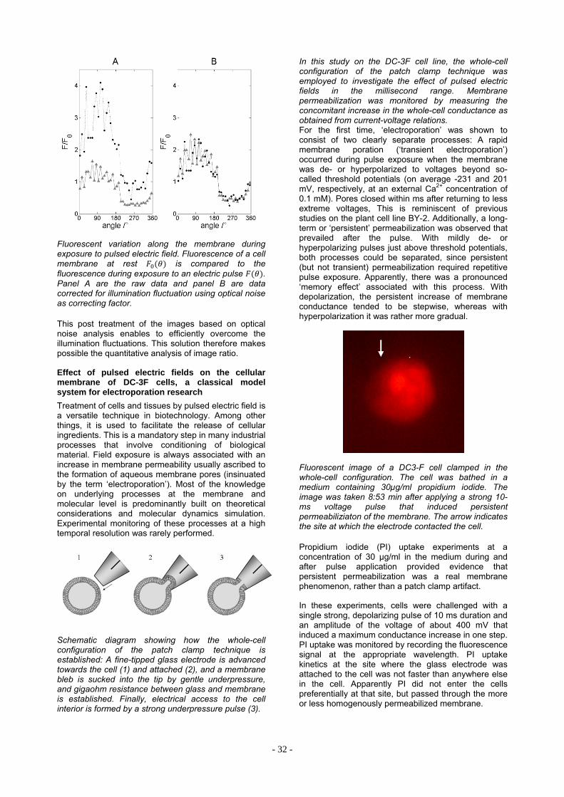
- 32 -
Fluorescent variation along the membrane during exposure to pulsed electric field. Fluorescence of a cell membrane at rest is compared to the fluorescence during exposure to an electric pulse . Panel A are the raw data and panel B are data corrected for illumination fluctuation using optical noise as correcting factor. This post treatment of the images based on optical noise analysis enables to efficiently overcome the illumination fluctuations. This solution therefore makes possible the quantitative analysis of image ratio.
Effect of pulsed electric fields on the cellular membrane of DC-3F cells, a classical model system for electroporation research
Treatment of cells and tissues by pulsed electric field is a versatile technique in biotechnology. Among other things, it is used to facilitate the release of cellular ingredients. This is a mandatory step in many industrial processes that involve conditioning of biological material. Field exposure is always associated with an increase in membrane permeability usually ascribed to the formation of aqueous membrane pores (insinuated by the term ‘electroporation’). Most of the knowledge on underlying processes at the membrane and molecular level is predominantly built on theoretical considerations and molecular dynamics simulation. Experimental monitoring of these processes at a high temporal resolution was rarely performed.
Schematic diagram showing how the whole-cell configuration of the patch clamp technique is established: A fine-tipped glass electrode is advanced towards the cell (1) and attached (2), and a membrane bleb is sucked into the tip by gentle underpressure, and gigaohm resistance between glass and membrane is established. Finally, electrical access to the cell interior is formed by a strong underpressure pulse (3).
In this study on the DC-3F cell line, the whole-cell configuration of the patch clamp technique was employed to investigate the effect of pulsed electric fields in the millisecond range. Membrane permeabilization was monitored by measuring the concomitant increase in the whole-cell conductance as obtained from current-voltage relations. For the first time, ‘electroporation’ was shown to consist of two clearly separate processes: A rapid membrane poration (‘transient electroporation’) occurred during pulse exposure when the membrane was de- or hyperpolarized to voltages beyond so-called threshold potentials (on average -231 and 201 mV, respectively, at an external Ca2+ concentration of 0.1 mM). Pores closed within ms after returning to less extreme voltages, This is reminiscent of previous studies on the plant cell line BY-2. Additionally, a long-term or ‘persistent’ permeabilization was observed that prevailed after the pulse. With mildly de- or hyperpolarizing pulses just above threshold potentials, both processes could be separated, since persistent (but not transient) permeabilization required repetitive pulse exposure. Apparently, there was a pronounced ‘memory effect’ associated with this process. With depolarization, the persistent increase of membrane conductance tended to be stepwise, whereas with hyperpolarization it was rather more gradual.
Fluorescent image of a DC3-F cell clamped in the whole-cell configuration. The cell was bathed in a medium containing 30µg/ml propidium iodide. The image was taken 8:53 min after applying a strong 10-ms voltage pulse that induced persistent permeabiliziaton of the membrane. The arrow indicates the site at which the electrode contacted the cell. Propidium iodide (PI) uptake experiments at a concentration of 30 µg/ml in the medium during and after pulse application provided evidence that persistent permeabilization was a real membrane phenomenon, rather than a patch clamp artifact.
In these experiments, cells were challenged with a single strong, depolarizing pulse of 10 ms duration and an amplitude of the voltage of about 400 mV that induced a maximum conductance increase in one step. PI uptake was monitored by recording the fluorescence signal at the appropriate wavelength. PI uptake kinetics at the site where the glass electrode was attached to the cell was not faster than anywhere else in the cell. Apparently PI did not enter the cells preferentially at that site, but passed through the more or less homogenously permeabilized membrane.

- 33 -
Current-voltage relations obtained in four successive runs on the same cell (different symbols, see legend in figure). The membrane was pulsed to trains of 10-ms pulses to various voltages. The current amplitude at the end of each pulse was plotted against the trans-membrane voltage drop (not identical with the clamped voltage; see previous publications) Inset: detail of the curve showing the shift in the slope of the current-voltage relation in the physiological voltage range with 3rd and 4th repeat of the same pulse sequence. The conductance increased at least 2 fold with respect to the first two sweeps. For more details, see text
The effect of a single, strong voltage pulse of both positive and negative polarity on post-pulse membrane conductance was also investigated in the absence of the dye, rendering very similar results. In this subset of experiments, current-voltage relations in the physiological range were recorded at different time intervals up to >40 min after imposing the conditioning pulse. In most cells, membrane conductance remained stable or decreased slightly during this time. Only in a few cases, the membrane conductance increased progressively, probably due to irreversible damage.
2 4 6 8 10 12 14 16 18 200,0
0,5
1,0
1,5
2,0
2,5
Spe
cific
mem
bra
ne c
ond
ucta
nce
(nS
/pF
)
Pulse number
Changes in membrane conductance induced by repetitive depolarization of DC-3F cellular membrane to 320 mV (clamped voltage) for 10 ms each. Membrane conductance after the pulse was monitored by stepping the voltage after each pulse first to 80 mV for 25 ms and subsequently to 0 mV for 5 s before the following pulse was applied; the conductance was calculated from the steady-state current level at 80 mV. Starting at a very low level membrane conductance increased stepwise, with pronounced changes at the 3rd, 4th and 10th pulse.
In conclusion, this study revealed that what is generally called ‘electroporation’ consists of (at least) two distinct processes, a transient poration in the presence of the electric field and long-term changes in membrane permeability. The latter effect, the ‘persistent electroporation’, is likely to be most relevant for applied aspects such as the forced release of cellular ingredients. Future work will focus on unraveling the molecular mechanisms that transduce short-term pulse exposure into longterm changes in membrane properties.
Bioelectrics 2013 – 10th International Symposium on Bioelectrics and COST TD1104 WG4 meeting at KIT, CN, Karlsruhe, September 16-19, 2013
This annual conference was established by the International Bioelectrics Consortium IBC (see also: http://ww2.odu.edu/engr/bioelectrics/consortium.html) as a platform for information exchange among the member institutions and guest institutions working in the area of interaction of pulsed electric fields and plasma with biological matter. A major objective of this year’s symposium was to establish cross-linking between the IBC and the European electroporation community associated with the COST TD1104 Action: “European network for development of electroporation-based technologies and treatments”.
The conference program was organized in 51 oral lectures subdivided into 11 oral sessions. 36 posters were presented within two poster sessions. The first day of the symposium was dedicated to lectures and reports from IBC-member institutions on basic and biological effects of pulsed electric field exposure, new diagnostic methods and advances in medical applications. The following two days focused on COST-working-group 4 topics “Environmental Applications and Biomass Processing”, aiming to provide recent research results and findings. These excellent scientific presentations gave an overview for discussing future activities of the WG 4 at the meeting scheduled for the last day of the conference.
Topics on environmental and biomass processing applications included: Microalgae processing for economic cell component extraction; bacterial disinfection; and recovery of valuable compounds from residual biomass from food industry and forestry. Also, technological aspects of high mass-flow biomass treatment applications were discussed. A special session focused on the impact of pulsed electric fields on the cell’s cytoskeleton.
After the two-days-lasting update on recent environmental and biomass processing applications, the first WG 4 meeting started with a summary on current member status and on working topics of WG 4. As also established in other WG meetings, incomplete treatment parameter description in publications was identified as one of the main hurdles in comparing and reproducing research results for different institutions. In particular, in the environmental and biomass processing area, review publications on the state of the art of PEF-processing and on research demand are missing. It was decided to start a review on microalgae processing and to identify main topics for subsequent review issues.
-300 -200 -100 0 100 200 300
-4
-2
0
2
4
Cur
rent
(nA
)
Trans-membrane voltage difference (mV)
-200 -100 0 100 200
-0.6
-0.3
0.0
0.3
0.6
1
2 3
4
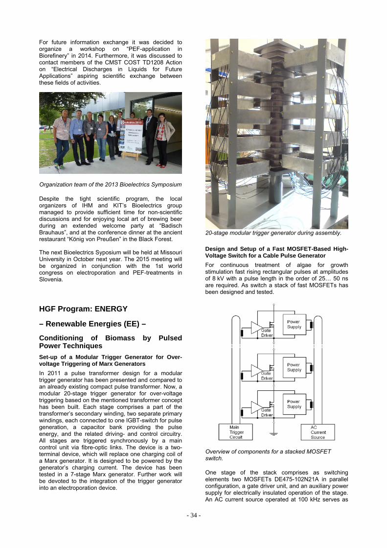
- 34 -
For future information exchange it was decided to organize a workshop on “PEF-application in Biorefinery” in 2014. Furthermore, it was discussed to contact members of the CMST COST TD1208 Action on “Electrical Discharges in Liquids for Future Applications” aspiring scientific exchange between these fields of activities.
Organization team of the 2013 Bioelectrics Symposium Despite the tight scientific program, the local organizers of IHM and KIT’s Bioelectrics group managed to provide sufficient time for non-scientific discussions and for enjoying local art of brewing beer during an extended welcome party at “Badisch Brauhaus”, and at the conference dinner at the ancient restaurant “König von Preußen” in the Black Forest.
The next Bioelectrics Syposium will be held at Missouri University in October next year. The 2015 meeting will be organized in conjunction with the 1st world congress on electroporation and PEF-treatments in Slovenia.
HGF Program: ENERGY
– Renewable Energies (EE) –
Conditioning of Biomass by Pulsed Power Techniques
Set-up of a Modular Trigger Generator for Over-voltage Triggering of Marx Generators
In 2011 a pulse transformer design for a modular trigger generator has been presented and compared to an already existing compact pulse transformer. Now, a modular 20-stage trigger generator for over-voltage triggering based on the mentioned transformer concept has been built. Each stage comprises a part of the transformer’s secondary winding, two separate primary windings, each connected to one IGBT-switch for pulse generation, a capacitor bank providing the pulse energy, and the related driving- and control circuitry. All stages are triggered synchronously by a main control unit via fibre-optic links. The device is a two-terminal device, which will replace one charging coil of a Marx generator. It is designed to be powered by the generator’s charging current. The device has been tested in a 7-stage Marx generator. Further work will be devoted to the integration of the trigger generator into an electroporation device.
20-stage modular trigger generator during assembly.
Design and Setup of a Fast MOSFET-Based High-Voltage Switch for a Cable Pulse Generator
For continuous treatment of algae for growth stimulation fast rising rectangular pulses at amplitudes of 8 kV with a pulse length in the order of 25… 50 ns are required. As switch a stack of fast MOSFETs has been designed and tested.
Overview of components for a stacked MOSFET switch. One stage of the stack comprises as switching elements two MOSFETs DE475-102N21A in parallel configuration, a gate driver unit, and an auxiliary power supply for electrically insulated operation of the stage. An AC current source operated at 100 kHz serves as

- 35 -
main power supply for the stack. The pulse generation of the stack is controlled by the main trigger circuit delivering a fast rising trigger signal to the stages.
14 stage elements have been manufactured and tested in different configurations. In a seven-stage configuration a total voltage of up to 5.6 kV has been switched into a 50 Ω load resulting in a current of up to 106 A at a measured rise time of 6.4 ns.
Voltage across and current through a 7-stage MOSFET switch during the moment of switching. A Blumlein-type cable pulse generator designed for 50 ns pulse length has been equipped with one 7-stage switch at the end of each transmission line in order to control the pulse length and pulse polarity across the matched load.
For evaluation purpose the switching delay has been varied between 5 ns and 50 ns at a voltage of 2 kV and 3.5 kV. At low switching delay the pulse amplitude is reduced due to the limited rise time.
Dual-switch configuration: Variation of voltage and switching delay.
For a 12-stage configuration a rise time of 8 ns at a voltage of 9.6 kV switched into a 50 Ω load has been achieved.
12-stage MOSFET switch. Involved Staff:
H. Brüsemeister, Dr. C. Eing, J. Fleig, Dr. W. Frey, Dr. C. Gusbeth, Frau DI M. Göttel, K. Leber, E. Menesklou, Dr. G. Müller, K. Paulus, D. Quattrocchi, Frau S. Rocke, Frau Dr. A. Silve, R. Stängle, DI R. Sträßner, Dr. M. Sack, Dr. L. Wegner (KIT-CS), R. Wüstner, H. Zimmermann
HGF Program: NUKLEAR
– Safety Research for Nuclear Reactors –
Corrosion and Wear Protection for New Reactor Technologies
To guarantee reliable future electricity supply new types of nuclear reactors are investigated in the frame of GEN IV. The development of technologies required for the safety of fast heavy metal cooled reactors like the Lead Fast Reactor (LFR) is the core area of the work performed at KIT. Especially the development of advanced materials e.g. ODS steels and the investigation and improvements of their compatibility with the proposed coolants are in the focus of this work.
Aim of the institute’s contribution is the development of corrosion barriers to improve the compatibility of new structural materials with liquid Pb or PbBi. Pulsed large area electron beams (GESA - process) are used to modify surfaces such that they satisfy the demands of their targeted environment. Corrosion test facilities for specimen exposure under relevant conditions and for combined loads like fretting or erosion together with corrosion are developed, built and used at the IHM. The conditioning and control of the required oxygen level in the liquid metal is an additional task of the work.
The entire activity is integrated in European and international projects and cooperation, e.g. LEADER and GETMAT. Both projects were finished this year and all contributions were delivered in time. In addition to the nuclear related projects a look ahead to the new involvement in non-nuclear fields was started with the CO2 free methane decomposition in liquid metals via a joint IASS-KIT project.
The most important results obtained in the reporting period are briefly presented:

- 36 -
Erosion tests of pump materials in CORELLA (LEADER)
The original design of the CORELLA facility did not allow testing the erosion stability at higher flow velocities than 2.5 m/s. A re-design using a different feed-through technology was successful and allowed rotation speeds of more than 1000rpm, which is sufficiently high for achieving Pb velocities larger than 10 m/s, which is comparable with the expected velocities at the pump impellers.
With this set-up two tests with different materials (Norihard, Noriloy, Si/SiC composite, T91/GESA surface alloyed, and Maxthal (type: Ti2SiC3)) were performed at 480°C. The first test was stopped after 100h, because the target oxygen content of 10-6 wt% oxygen could not be achieved. The real oxygen content measured with an oxygen sensor was below 10-9wt% oxygen. However, the samples were investigated and only at the sides facing the flowing Pb some damage was observed.
For Maxthal it was very difficult to detect erosion due to the non-perfect sample preparation. From the other tested material Noriloy with higher Cr shows the best behaviour. The worst behaviour was observed for T91 material at the non-modified side facing the flowing Pb, at which up to 50µm deep erosion was detected. The other side and the rest of the specimen were basically unaffected. The Si/SiC composite specimen got lost during the 100h. The free Si might have been dissolved at these conditions or the mounting might have been broken.
The second test ran for 780h in Pb with the expected oxygen content of 10-6 wt% or a slightly higher one. With exception of Maxthal the same materials were tested.
From a macroview basically no severe damage is visible. All specimens look more oxidized than the 100h equivalent ones. The Si/SiC composite specimen did not look too nicely after Pb removal (cleaning solution also attacked the Si/SiC specimen). As for the 100h specimens also the ones exposed for 780h were investigated using stereo microscopy at both sides, the front side that was directly exposed to the flowing Pb (here the largest damage is expected) and its opposite side.
As after the 100h test, the front side of the Norihard sample facing the flowing Pb shows slight attack at the outer edge in comparison to the opposite side. The rest of the sample exhibits no further visible damage due to the flowing Pb. Very similar to the Norihard was the behaviour of the Noriloy specimen. Only at the outer edge of the side facing the Pb slight damage is visible at the picture. The rest of the specimen does not show damage due to the flowing Pb.
LOM of Norihard after 780h in CORELLA. Left- front side facing flowing Pb – right: opposite side
The surface profile of the Norihard 780h specimen reveals a slight damage at the edges. At about 100µm from the edge, up to 30µm of material is removed by the impinging Pb, which is an attack quite similar to the 100h specimen. However, only at this specific location some damage was observed.
The Noriloy specimen shows only little damage, even after 780h. At the outer edge of the Pb facing front about 40 µm material loss in a depth of about 50µm is observed. The entire rest of the sample is not attacked by the flowing Pb.
LOM of T91/GESA after 780h in CORELLA. Top left – front side facing flowing Pb, top right – opposite side (both sides not surface alloyed); bottom – GESA surface alloyed sides of the specimens
The most severe and in comparison to the 100h duration enhanced attack happened at the non-modified part of the T91/ GESA surface alloyed sample. The original T91 shows a clearly visible attack, see the respective LOM images. The positive influence of the GESA surface alloying can be seen in side view. The non-modified T91 at the Pb facing front shows damage while the surface alloyed part is basically unchanged. At the back side (not Pb facing) both the T91 and the GESA surface alloyed parts are not attacked. Profilometry reveals a material loss of up to 150µm over a distance of more than 1.5mm from the edge on the Pb flow facing side. The non-modified T91 is clearly not able to withstand such conditions. However, the GESA surface alloyed T91 seems to be compatible with the experimental conditions.
Profilometry data of T91/GESA - specimen (780h) front side facing the Pb flow: height profile at two different positions More detailed and specific experimental work regarding the erosion stability of materials is required. It is clear also from these experiments that the localized flow patterns have to be considered. It is yet not possible to identify a specific velocity range above

- 37 -
which flowing Pb will induced erosion damage to materials. The selected “hard” steels (Noriloy and Norihard) behave much better than T91 in original state. Also the GESA surface alloyed T91 shows much better resistance than the original T91. The Maxthal seem to be resistant, however a final statement can not be drawn at time due to the missing sample in the second experiment. Si infiltrated Si/SiC composite can not be used in reducing conditions. The free Si seems to be dissolved easily by the liquid metal.
Compatibility of welds with Pb alloys.
Within the GETMAT project welded ferritic/martensitic (f/m) and ODS steels were tested in liquid lead to investigate the behavior of the welds. Due to the fact that some welds were delivered with a delay an additional run of exposure test were conducted. Four specimens were tested, two T91 specimens welded by friction stir (one with and one without heat treatment), a 14Cr ODS specimen welded by explosive welding and a T91 specimen welded by electro-magnetic pulse welding. They were exposed in lead containing 10-
6wt% oxygen up to 1342h, with exception of the electro-magnetic pulse welded specimen, which was exposed for 2131h.
In contrast to the previously tested T91 friction stir welded specimen without heat treatment, the new delivered sample showed in the welded region no change in the behavior. A multi-layer scale consisting of magnetite, Fe-Cr spinel and inner diffusion zone (IOZ) was formed at the entire surface. The difference to the previously tested sample was the microstructure of the weld region. In the actual specimen the interfaces between the T91, the heat affected zone (HAZ) and the welded region were hardly detectable due to their similar microstructure. Changes in the microstructure (grain size, etc.) can result in different diffusion rates, which is finally co-responsible for an increase or a decrease of the oxide layer thickness. Due to larger grains in the HAZ compared to the weld region, the diffusion of oxygen into the steel was most likely reduced, which results in a smaller IOZ in the HAZ. The spinel and magnetite layer were basically unaffected.
Photo of T91 friction stir welded and heat treated after exposure to lead with 10-6wt% oxygen at 550°C showing the oxide layer on the border of HAZ and weld region with an increased IOZ. A large influence on the oxide layer thickness was detected by the specimens manufactured by explosive welding. On the surface of the original no welded part an about 14µm thick oxide layer was formed consisting of magnetite and spinel. At the weld region a thinner oxide layer (<1µm) also consisting of magnetite and spinel developed. This remarkable difference can only be explained by microstructural features like the dislocation density and not by effects of a changed chemical composition.
A T91 tube was welded with an end cap by electro-magnetic pulse welding. The cross section on the right side shows the part before the weld region starts. A 70µm long gap between the end cap and the tube is observed at this region. This gap oxidized during the exposure without penetration of Pb. The oxide consists of magnetite, spinel and an IOZ. The welded area without the gap was not influenced due to the oxidation. To evaluate the behavior in time of the oxidized gap longer exposures are recommended.
T91 tube welded with an end cap by electromagnetic welding; left – tube with end cap inside after welding; right cross section of the beginning of the welded part. Heat transfer properties of oxidized T91 steel in contact with molten lead.
In order to be used in molten lead, structural materials, such as f/m T91 and austenitic steels, must be protected to avoid excessive corrosion by dissolution of component elements. Controlled oxygen content in molten lead is required, allowing the formation of thin, compact and stable oxide layers for operating temperatures lower than 500°C. Protective surface treatment is additionally required for operating at temperatures higher than 500°C. The surface protection, regardless of its type, could influence the heat transfer capability and therefore it is necessary to gain knowledge concerning the thermal diffusivity/conductivity of the steel, of the steel with protective layer and of the heat contact resistance between the steel with protective layer and liquid lead.
The measurements of thermal diffusivity were performed with a non-contact method called laser flash technique on T91 steel, nickel and T91 coated with 30 m Fe-Cr-Al-Y modified layers.
The samples’ thermal diffusivities were measured in the initial state and after oxidation either in oxygen containing molten lead or in air at 550 and 650°C.
The evolution of the thermal diffusivity of non-oxidized T91 steel measured from room temperature to 650°C was compared with the thermal diffusivity of P92 steel and of T91 covered with modified Fe-Cr-Al-Y layers using pulsed electron beams (GESA –process).
Measured thermal diffusivities of non-oxidized T91 and T91+Fe-Cr-Al-Y GESA-modified layer compared to P92 values.

- 38 -
Samples made of T91 and T91 covered with GESA-modified Fe-Cr-Al-Y layer were oxidized on one side, in oxygen-containing molten lead, at 550°C for 2500 hours. The oxide scale formed on these samples consisted of 30 m duplex scale (Fe3O4 + FeCr2O4) on T91 and 0.5 m alumina scale on T91 with GESA-modified Fe-Cr-Al-Y layer.
The apparent thermal diffusivity of the oxidized samples was measured between room temperature and 650°C. The apparent diffusivity of the oxidized T91 decreased, due to the oxide scale, by 10.3% from the initial value (non-oxidized sample) at room temperature and by 3.4% at 650°C, while the decrease of the apparent thermal diffusivity of T91 with GESA-modified Fe-Cr-Al-Y surface layer was by 3% at RT and by 2.75% at 650°C.
The heat contact resistance between the oxidized T91 steel and the molten lead was determined using measured diffusivities and heat capacities of T91, molten lead and Fe-based duplex oxide. In addition, the heat contact resistances with molten lead of three other samples were evaluated: non-oxidized T91, Ni covered with 0.4 m Au layer and T91 covered with 0.4 m Au layer. The deposition of the gold layer on Ni and T91 was performed in order to obtain a reactive wetting. During the reactive wetting phenomenon, interfacial reactions lead to the formation of continuous layers and in consequence to an improved thermal contact.
The apparent thermal diffusivity of the oxidized T91 and T91 with GESA-modified Fe-Cr-Al-Y coating compared with the thermal diffusivity of non-oxidized samples made of the same materials
The higher value of heat contact resistance, obtained for non-oxidized T91, can be explained by the low wettability of the molten lead on the polished surface of T91, most probably covered by a very thin oxide scale.
Heat contact resistances with molten lead of the non-oxidized T91, Ni covered with 0.4 m Au layer, T91 covered with 0.4 m Au layer and oxidized T91 (covered by an approx. 15 m Fe-based duplex oxide layer)
In conclusion:
the heat transport properties of T91 steel, non-oxidized and oxidized were determined from room temperature up to 650°C. In this interval the thermal diffusivity varies between 8.51 and 4.6 x 10⁻⁶ m2/s and the thermal conductivity between 31.8 and 32.32 W/mK.
the thermal diffusivity of the Fe-based duplex oxide was determined in the temperature range: RT to 650°C. It was found to vary between 0.27 x 10⁻⁶ and 0.168 x 10⁻⁶ m2/s.
the thermal diffusivity of the molten lead was measured to be between 10 and 12.17 x 10⁻⁶ m2/s in the temperature range 330 – 650°C.
the heat contact resistance between oxidized T91 steel and molten lead was determined for the temperature range 400-600°C to be around 2x 10⁻⁵ m2K/W.
Measurement and Simulations of Electron Beam Precession in Gesa 1 and Gesa 2 Facilities
For a better understanding and control of the surface alloying process all aspects of the electron beam material interaction has to be understood. One prominent feature of the long pulse electron accelerator GESA is the precession of the beam around its symmetrical axis with a frequency of about 1 MHz. The nature of such precession depends strongly on the configuration of the magnetic field, the target material and the dynamic of the cathode plasma. Variation of the mirror coefficient (Bc/Bt) und the strength of the magnetic field at the cathode, Bc, allows controlling amplitude and frequency of precession. The higher the density (Z) of the target, the earlier the precession starts and the lower its frequency will be.
Scheme of the GESA I and II facility showing the magnetic field system Comparing the precession with the well-known spatial pulsation of the beam profile depicts the similarity to the starting conditions for both phenomena. Comparison of the results of x-ray beam diagnostics and of a PIC code simulation (Esray) suggests that the pulsation of the beam, triggered by non-perfect beam - magnetic field coupling, is correlated with the precession.

- 39 -
Scintillator: Lu1.8Y.2SiO5 (St. Gobain Crystals) Density – 7.1g/cm³ Absorbtion for 100kV, 1.8mm ~97% Decay time - 41 ns Wavelength of Emission – 420nm Photoelectron yield – 75% of NaJ Framing Camera - DiCam Pro PCO, Exposure Time – 40ns Streak Camera – C7700 Hamamatsu, Streak Length – 100µs
X-Ray beam diagnostic to measure the precession of the electron beam
Mirror coefficient Bc/Bt=10.5; magnetic flied near cathode Bc~0.015T. With an optimized magnetic field configuration precession is only scarcely visible. The beam cross-section is homogenous and axial symmetric with a minimal radial pulsation of the beam profile.
Mirror coefficient Bc/Bt=17.5; magnetic field near cathode Bc~0.010T An arbitrary magnetic field configuration results in strongly pronounced precession with large amplitude. In addition the beam profile becomes inhomogeneous and asymmetric with an intensive radial pulsation. The rotation of the beam around its own axis starts after about 5-8 µs.
A clear correlation between precession and spatial pulsation of beam profile was observed. One possible explanation is the movement of the cathode plasma that results in a continuous increase of the perveance and also changes the character of the pulsation. The inhomogeneity of the plasma front makes the changes additionally dependent from the radius. After 5-8µs the collective dynamics of the outer electrons is in addition
influenced by the rotation of the beam; the outer electrons move along a helical path. The azimuthal position of helical profile at the target is continuously changed by the rotation of the beam. This phase change may be perceived as precession. The estimated rotation frequency of the beam is similar to the frequency of the precession in the MHz range.
– Transmutation - Liquid Metal Technology –
Materials and oxygen transport and control in heavy liquid metal cooled subcritical systems (MYRRHA)
Long-living high-level radioactive waste from existing nuclear power reactors should be transmuted in short-living radio nuclides using fast neutrons provided by a spallation target in an accelerator driven subcritical system or by a fast nuclear reactor. The objective is to reduce the final disposal time of high-level radioactive waste (plutonium, minor actinides) from some 106 years down to about 1000 years. Lead (Pb) and lead-bismuth (PbBi) are foreseen as spallation-target and coolant of such devices.
The aim of the institute’s contribution is the development of a suitable corrosion protection especially for parts under high thermal loads like fuel claddings or pump materials in contact with liquid Pb or PbBi. Pulsed large area electron beams (GESA) are used to modify the surface of steels such that they fulfil the requirements of their surrounding environment. Corrosion test stands for exposure of specimens under relevant conditions are developed and operated. Test facilities for combined loads like erosion and corrosions and fretting corrosion were developed, built and operated. Conditioning the lead with regard to its oxygen concentration and the transport of oxygen in PbBi are additional aspects of the work.
All tasks are embedded in European and international projects and cooperation e.g. MATTER, SEARCH. Two new EU projects continuing the previous work were started at the end of 2013, ESNIIplus and MaTISSE.
The most relevant results obtained in the reporting period are briefly presented:
Stability domain of thermally grown alumina on Fe-Cr-Al-base alloys and layers exposed to molten Pb
Heavy liquid metals (HLM), namely lead and lead-based alloys, are currently under consideration for energy-related applications (e.g. hydrogen production, concentrated solar power and nuclear reactors) due to their low reactivity versus oxygen and water and their beneficial thermal and neutronic properties.
However, HLM compatibility with structural steels, in terms of corrosion and mechanical resistance, causes considerable concern. While at temperatures below 500°C, the corrosion issue was solved for both austenitic and ferritic/martensitic steels, with the aid of a protective Fe-based oxide scale grown by adding small quantities of oxygen into HLMs, at higher temperatures an acceptable solution is still under debate.

- 40 -
For this latter case (T > 500°C), in a first attempt, steels alloyed with strong oxide-forming elements (e.g. Al, Si) were tested in lead and lead-based alloys containing small amounts of oxygen (10-8-10-6 wt%). The protection of such steels was provided by a thin, continuous oxide scale, grown during the exposure to oxygen-containing HLM. The key factor of this behaviour consists in the appropriate Al or Si concentration, leading to their selective oxidation.
Unfortunately, in the case of Al addition, the minimum content required might negatively affect the mechanical properties of the steel. This is the reason why, for the protection against corrosion attack above 500°C Al-containing layers (e.g. Fe-Cr-Al-Y), deposed by plasma spraying and subsequently modified using intense pulsed electron beams (GESA process), were proposed instead of alloying the steel with Al.
The current report presents a synthesis of the results concerning the corrosion behaviour of GESA-modified, Fe-Cr-Al-based layers and of bulk Fe-Cr-Al model alloys, during their exposure to oxygen-containing lead (10-6 wt. %), in the temperature range between 400 and 600°C.
The study was performed on:
rapidly solidified layers, with wavy surface topography, refined microstructure (grain size 0.5 - 2 µm) and local fluctuation of Al/Cr concentration, allowing the evaluation of the oxidation behaviour for a range of Al/Cr contents within only one nominal composition, using scanning electron microscopy combined with energy dispersive spectroscopy (SEM/EDX).
bulk alloys with very large grains (0.5 – 2 mm), so that a possible influence of grain boundary diffusion on the formation of oxide scales was very low. The specimens showing a smooth surface aspect were analysed using surface characterization techniques: X-ray photoelectron spectroscopy sputter depth profiling (XPS-SDP) and grazing incidence X-ray diffraction (GI-XRD).
This combinatorial approach was designed for efficient mapping of the alumina stability domain in Fe-Cr-Al ternary diagrams, for the definition of experimental criteria concerning Al/Cr ratio optimization and for the determination of alumina polymorph, formed at different temperatures on Fe-Cr-Al alloys and surface layers.
Samples of 9Cr ferritic/martensitic T91 steel were coated, using low pressure plasma spraying method (LPPS), with Fe-Cr-Al-base layers. Because of the high porosity and poor bonding to the substrates, the as-sprayed coatings, together with some micrometers thick layers of the substrates, were melted by intense pulsed electron beams in the GESA facility. Melting and rapid solidification of the approximately 30 µm thick surface layer leads to an Al-containing and dense surface region, with refined microstructure and good bonding to the underlying steel.
Twelve Fe-Cr-Al model alloys were also prepared as ingots by arc-melting in argon atmosphere starting from high purity elements.
All specimens, modified Fe-Cr-Al layers (A1-A4, B1-B4) and Fe-Cr-Al model alloys (P1 to P12), were exposed to stagnant liquid lead containing 10-6 wt.% oxygen.
XRD patterns of P4 (Fe-14Cr-4Al) - a) and P8 (Fe-12Cr-7Al) - b) taken after exposure in oxygen containing liquid lead at 450°C and 550°C respectively. A duplex layer (Fe3O4+Fe(Cr,Al)2O4) is grown on P4 sample, while on P8 the scale is k-Al2O3 alumina polymorph.
XPS compositional sputter depth profile of P9 (Fe16Cr6Al) at 450 (a) and 550 (b)

- 41 -
Three bulk alloys (Fe-16Cr-6Al, Fe-12Cr-8Al, Fe-16Cr-8Al) and four modified surface layers (Fe-14Cr-11Al, Fe-14.5Cr-10Al, Fe-13.5Cr-9Al, Fe-9.5Cr-10Al) were found to form alumina as protective oxide scale against corrosion in oxygen-containing lead. All the others samples developed a fast growing Fe-rich duplex scale during their exposure.
Based on these results, the stability domain of alumina has been estimated for the Fe-Cr-Al alloy system, exposed to molten lead containing 10-6 wt% oxygen, over 400-600°C temperature range.
Two types of alumina polymorph were found to grow as protective scale during exposure to molten lead: k-Al2O3 (400-550°C) and -Al2O3 (600°C).
The experimentally determined criteria for the minimum concentration of Al necessary to form alumina scale on Fe-Cr-Al alloys exposed at 400-600°C in molten lead is:
C Al =1.53 – 0.81 (CCr) + 0.02 (CCr)2 [wt%] when CCr =
12-25 wt.%.
Oxide “map” for the oxidation of Fe-Cr-Al-base model alloys exposed to oxygen containing molten lead, in the temperature range 400 – 600 °C
Fretting of fuel clad materials in liquid Pb
During the fretting tests some handling difficulties and measurement issues become obvious. In the frame of a bachelor thesis the device was optimized to increase the reliability and repeatability of the experimental results. One of the objectives was to achieve by design a horizontal alignment of the counter specimen. In addition a more precise Z-movement of the counter specimen was realized and the amplitude variation device was optimized.
Steels as structural material for use in Pb /PbBi alloys –contribution to the OECD handbook
A new version of the „Handbook on Lead-bismuth Eutectic Alloy and Lead Properties, Materials Compatibility, Thermal-hydraulics and Technologies“ will be published by the OECD. An update of chapter 9 “corrosion protection” and, due to our expertise on the corrosion field in heavy liquid metal, a new version of chapter 6 “compatibility of structural materials with LBE (lead-bismuth eutectic) and Pb” were done. Up to now compatibility tests with a large variety of materials at varying conditions have been carried out both in stagnant and flowing LBE/Pb. By considering all data that are relevant for the judgment of material suitability for application in LBE/Pb cooled systems the
operational windows for austenitic and ferritic/martensitic steels in dependence on oxygen content and temperature were determined.
The behaviour of ferritic/martensitic steels shows two clearly defined regions. At higher oxygen content protective oxide scales are formed and at lower oxygen content LBE/Pb attack on steel takes place. The border between both regions is the dashed line drawn from the first data point at 300°C/10-8wt% oxygen to 450°C/10-8wt% and then with increasing oxygen concentration up to 550°C/10-5wt%. The diagram shows that the conditions of compatibility between steel and LBE exist inside a large region of temperatures up to 550°C and oxygen concentrations down to 10-8wt%. Above 550°C there is a large risk of scale failure and dissolution attack onto the steel. When failure occurs, it happens mainly before 4000h exposure is reached. It should be noted that exposure times of only two protected steels reached 10000h and one 15000h in the temperature range 450-550°C.
Like for the f/m Fe-Cr steels, the diagram for austenitic steel is divided in two parts, separated by the line from 400°C/10-8wt% to 500°C/10-5wt% up to 540°C/10-
3wt%. It should, however, be noted that above 500°C the risk of dissolution attack by leaching out of Ni is high. At 550°C all the specimens fail even in LBE saturated in oxygen.
250 300 350 400 450 500 550 600 650 7001E-12
1E-11
1E-10
1E-9
1E-8
1E-7
1E-6
1E-5
1E-4
1E-3
0,01
loop oxide static corrosion static oxide loop corrosion static 12 Cr oxide loop 12Cr corrosion loop 12Cr oxide Static 12Cr corrosion
oxyg
en c
onte
nt [
wt%
]
temperature [°C]
9Cr and 12Cr F/M steels (2000h)
Fe-Cr steels after exposure to LBE/Pb at temperatures ranging from 300-650°C (top - for ≥ 2000h), Fe-Cr-Ni steels after exposure to LBE/Pb at temperatures ranging from 300-600°C (bottom for ≥ 2000h) Oxygen control for ALFRED and EFIT
To design an oxygen control system for ALFRED the expected amount of oxygen that is consumed by steel oxidation has to be evaluated. Based on available data the oxygen consumption was calculated for the EFIT reactor. This evaluation considers a realistic operation

- 42 -
scenario and start-up of a reactor. Oxygen consumption considering the actual configuration (materials, temperatures, surfaces in contact with liquid Pb) is calculated for different phases of operation: commissioning phase at 400°C for 4000h; fuel assembly input at 400°C for 1000h; physical commissioning, step wise power increase to 100% in 300h; full power operation 1year; one shut down at 400°C in between; 1/3 fuel assembly exchange at 400°C; steam generator (SG) tube exchange at 400°C. The materials used are T91 and 316L and in addition surface aluminized T91 is discussed too.
As shown in the figure below, 9.3·10-2kg/h of oxygen is needed in the beginning to satisfy the consumption of oxygen due to oxidation of the fresh metal surfaces in the reactor at 400°C. This demand drops down quickly to below 2·10-2kg/h because of the diffusion barrier built up by the growing oxide scale. Before exchange of dummy against fuel pin assemblies after 4000h the consumption arrives at the low rate of 2·10-3kg/h. Between 4000 and 5000h consumption increases slowly because of the fuel pin assembly oxidation. After the short zero power period the peak up to a rate of 5.5·10-2kg/h represents the increase from zero power to full power within 150h. The first power period ends at 13700h residence time for exchange of 1/3 of the fuel pin assemblies during the following 500h. The jump to full power after shut down causes again a peak with a maximal rate of 3.5·10-2kg/h. The next peak at 16700h marks the insertion of SG-tubes which happens at once and at 17200h finally appears the peak that occurs when full power is approached with a power increase to 100% in 150h. This peak reaches a level of 3.7·10-2kg/h. When full power was applied at once, this peak could reach 1.2·10-1kg/h, however, the average consumption would be the same.
Oxygen consumption rate at different operating regimes
Despite of the low temperature of 400°C in the commissioning phase the oxygen consumption rate of 9.3·10-2kg/h is still very high for the system during the first few hours. This poses the most severe problem, since during the first 100h 2.3kg of oxygen must be delivered to the system to keep the oxygen content above the target concentration of 10-6wt%. The way to satisfy this high demand may be to feed in the beginning controlled amounts of PbO or to start with a much higher oxygen concentration in the HLM coolant. In both cases, however, it is necessary not to exceed the saturation concentration of oxygen in the low temperature region of the loop. A system like the EFIT reactor containing 6450t of lead with temperatures of 400 – 480°C could start with an oxygen concentration of 10-4wt% at 400°C in the pre-oxidation phase and, thus, contain 6.45kg oxygen that can be consumed
before the target concentration 10-6wt% is reached, which would be the case after 500h. Another 3·10-
3kg/h oxygen have to be delivered steadily during the whole commissioning phase to replace the oxygen that is consumed after the demand of the first consumption peak is satisfied.
During the first 500h after start of reactor operation (t = 5150 – 5650h) 15kg of oxygen have to be fed to stabilize the protective oxide layers on the surfaces. This leads to average transfer rates of 3·10-2kg/h and to the necessity of a large exchange surface. It may be a solution if the whole surface of the reactor pool would be employed for this purpose. Another possibility would be to add oxygen by solution of PbO. A combination of gas phase transfer and PbO solution in periods of high consumption rates is another possibility. By this method one could keep the advantage of oxygen delivery by gas phase transfer during the major part of reactor operation.
An overview on the oxygen consumption of the reactor and its considered substructures is given in the table below. It contains the oxygen consumption in the phase of commissioning that has a constant temperature of 400°C up to 4000h residence and that during the life time at full power in the first year. In the third line the consumption is listed for the same full power conditions when the fuel pin parts in the high temperature region (400-480°C) and (480°C) as well as the SG tubes (400-480°C) have a surface protection that allows very low oxidation rates like that of alumina scales. Looking at the total oxygen consumption of 75.6 kg for unprotected structures an average transfer rate of 8.6·10-3kg/h would be necessary to satisfy the demand. For a transfer through the gas phase with a rate like in the CORRIDA experiments this would require an exchange surface of 86m2
which is about 14% more than the pool surface.
Structures / oxygen consumption
fuel pin ass.
SG tubes
others total
commissioning phase, 4000h, [kg]
5.9 4.2 8.3 18.4
1 year full power on untreated surfaces, [kg]
27.1 20.8 27.7 75.6
1 year on treated high T f.p. & SG tb’s., [kg] – ALFRED
5.1 <0.5 27.7 33.3
Oxygen consumption in an EFIT reactor for the time of commissioning at 400°C, for 1 year of full power operation with normal surfaces and with highly loaded surfaces treated by protective Al-alloying (high temperature parts of fuel pins, SG tubes).
Cumulative oxygen consumption for different arrangements.

- 43 -
It is obvious that oxygen delivery could be much easier satisfied when the oxygen consumption rate would be much lower than calculated for the unprotected metal surfaces. Therefore, it would be a great advantage if highly loaded surface parts, like pins and heat exchanger tubes, had an alloyed surface that allows formation of thin stable oxide scales like alumina.
The oxygen demand of the core with partly alloyed surfaces is cut down to 4kg of oxygen in the first 500h, i.e. an average consumption rate of about 8·10-3kg/h. The consumption with unalloyed steel surfaces is 6.5kg during that time. The difference becomes larger when operation is started. Up to 1000h the reactor containing the protected surfaces need 10kg oxygen, the normal ones 22kg. Breaks in the slope of the curves happen when fuel assembly loading is finished and when reactor operation starts after 5150h. It is obvious that more than half of the oxygen consumption can be avoided when the high temperature part of the fuel pins and the SG-tubes are surface alloyed with alumina. In addition, surface treatment on highly loaded fuel pin surfaces keeps oxide scales thin and, thus, avoids high thermal barriers for the heat flow that result in high thermal gradients in the oxide scale.
Optimisation of the GESA process:
The remelting of metallic specimens using intense pulsed electron beams (GESA) results in a more or less pronounced waviness of the surface, which may be disadvantageous for some applications.
GESA beam-target interaction
In order to optimize the GESA remelting process of metallic surfaces and to understand the origin of wave-like structures observed on the target surface after resolidification, a sound knowledge of the beam-target interaction is required. In previous years, various fast in-situ optical diagnostic tools, among them streak imaging of the specular target surface reflectivity, spectroscopic analysis, side view high resolution and schlieren imaging, were set up to investigate the physical processes involved in the treatment. Finally, multiple exposure imaging of the target surface was implemented and tested. Due to the limited time resolution at that time (20 µs between consecutive exposures at best), however, conclusions on the target surface dynamics were very restricted.
In the reporting period, an enhancement of the time resolution of the stroboscopic illumination by an order of magnitude (2 µs between consecutive exposures) could be achieved. In addition, the GESA configuration was optimized, and a pulse duration control unit was introduced. Typical accelerating voltage and target current waveforms of the optimized pulses are summarized in the figure, together with a typical pulse prior to the GESA modification. The electron beam pulses of the new configuration are well controlled and show very good reproducibility. In addition, the large increase of target current around beam termination is avoided.
Accelerating voltage and target current waveforms of electron beam pulses prior to GESA modification (top) and after GESA optimization.
To acquire multiple exposure images of the target surface during treatment, stroboscopic illumination (flash duration 0.1-0.4 µs, time between flashes 2-50 µs) in combination with streak imaging was used. Slit width and streak speed were chosen such that the final image was composed of consecutive, non-overlapping snapshots. Experiments were performed on stainless steel (SS), copper (Cu), and aluminium (Al) targets, and various stages of electron beam treatment were investigated. Concentrating on the melting process, a coarsening of small (~10 µm) surface features was detected, most noticeable on SS. Besides, the transition from solid to melt appears rather smooth. There are no bubbles or droplets observed. On Al targets, a ‘dark’ period is found with less contrast, cf. the first few snapshots in the figure. This effect might be explained by intensive outgassing.

- 44 -
Multiple exposure micrograph of aluminium target surface, synchronized with voltage and current waveforms and pyrometer measurement. Time between snapshots 2 µs. Focusing the multiple exposure imaging investigations on the solidification process, again a smooth transition is found. It should be noted that the target surfaces in the new experiments do not exhibit the pronounced wave-like structures as observed previously, i.e., prior to GESA modification. This could be simply due to the reduced energy density of only ~30 J/cm² delivered to the target, in contrast to ~100 J/cm² before. Another substantial difference in electron beam characteristic and possible cause of the development of surface waviness, however, is the large increase of target current at beam termination (short-circuiting), which is completely avoided by the pulse duration control unit in the new configuration.
For a comprehensive understanding of the physical processes involved in pulsed electron beam treatment, in addition to the experimental investigations, simulations of GESA treatment of metal targets were performed using the code MEMOS. After validating previously the heat transfer and phase transition predictions by comparison with experimental results, investigations in the reporting period were focused on the hydrodynamic behavior of the melted surface layer. In the simulations shown below, a Gaussian beam profile with various beam diameters was used. A rectangular pulse was chosen, with 50 µs pulse duration, 120 keV electron energy, and 1.5 MW/cm² power density in the beam centre. The response of stainless steel, copper, and aluminium targets to electron beam treatment is summarized in the figure.
Response of stainless steel (first row), copper (second row), and aluminium (third row) targets to pulsed electron beams with three different beam diameters (w denotes the full width at half maximum). Left column: Maximum lateral melt velocity (reached after ~70 µs). Right column: Surface profile after treatment, without considering melt motion (‘evaporation’) and including melt motion.
Melt motion is driven by pressure gradients and tangential stresses at the melt surface. In the reporting period, the effect of lateral temperature gradients was investigated, which leads to thermocapillary flow (Marangoni effect). In the shown example, the surface temperature at the beam centre reaches ~3000 °C for all three target materials. The less is the beam diameter, the higher are the lateral temperature gradients and melt velocities. For typical beam diameters used in GESA applications (w ~ 5 cm), only aluminium is expected to exhibit a measurable effect of the finite beam diameter on the final surface profile. Although stainless steel shows similar melt velocity, due to the much shorter life time of the melt the effect of thermocapillary flow on the target surface profile is negligible.
Oxygen transport measurements in liquid PbBi (SEARCH)
Within the SEARCH project a dedicated facility to measure adsorption, entrainment of oxides in heavy liquid metals and mass transport phenomena in liquid metals was designed and constructed. This facility will be used to measure the transport of oxygen and of metal (oxide) particles. This work was accompanied by CFD calculations performed by colleagues of the IKET already in the design face. The measurement results finally will be used to qualify and optimize the CFD codes with respect to particle (oxide) transport into and in the liquid PbBi.

- 45 -
Photo of mini reactor to measure oxygen transport in liquid PbBi The device consisting of three pots is fully assembled and all electrical connections (heaters, motors and sensors) are commissioned and fully functional. First tests with water were done and the PbBi is now filled in the conditioning chamber.
The home-made pump was also designed and constructed based on CFD simulations. To guarantee a stable flow field the simulations clearly showed that nozzles are required at the flow outlets.
Simulation of PbBi pump for mini reactor and manufactured pump.
Seven oxygen sensors each accompanied by a thermocouple are manufactured and two UDV (ultra sound Doppler velocimeter) sensors are purchased and assembled to the device. The location of the UDV and oxygen sensors was determined by CFD calculations.
Simulated flow velocity at the measurement position of one of the UDV sensors
Involved Staff:
DP. W. An, R. Beckers, Fr. Dr. Renate Fetzer, Fr. Dr. A. Heinzel, DI (FH) F. Lang, Dr. A.Jianu, Prof. Dr. G. Müller, Dr. G. Schumacher (Gastwissenschaftler), A. Sivkovich, Dr. A. Weisenburger, DI (FH) F. Zimmermann
HGF Program: Energy
– Rational Energy Conversion (REUN) –
Dielectric Measurements
To allow for substantial efforts in modelling and design of microwave systems and processes the knowledge about the dielectric response of the material involved is an essential prerequisite. Therefore various test sets for dielectric measurement are currently under development.
Waveguide Method
A transmission-reflection method based on a WR-340 waveguide (shown in next figure) has been further improved. This test set allows for temperature dependent dielectric characterization of dielectric materials with medium and high loss factors.
By application of a homemade MATLAB code the system has been used for temperature and time dependent dielectric monitoring of the curing process of various epoxy resins. Since in the noncured state resins are liquid, the resins in various compositions were filled in a rectangular PTFE crucible and placed in the center of a waveguide sample holder. The waveguide sample holder is equipped with PID controlled resistive heating elements. This allows controlling of the sample temperature along any preset temperature-time profile.

- 46 -
Dielectric measurement setup for monitoring curing process Finally the dielectric properties were calculated from the scattering parameters measured by using a vector network analyzer (VNA). First results for the time dependent dielectric properties of such a curing process at constant temperature are shown in the next figures for bisphenol A diglycidyl ether (DGEBA) mixed with a polyetheramine D230 hardener (PEA D230). Those measurements show the progress of the curing process with time. As soon as there is no further decrease in dielectric constant or loss factor the curing process is finished.
Dielectric constant of DGEBA with PEA D230 during curing
Dielectric loss factor of DGEBA with PEA D230 during curing
Cavity Perturbation Method
The test set for high temperature dielectric characterization of materials based on cavity perturbation method developed at IHM in 2012 has been used to support different running projects.
In support of the MACOS project for microwave assisted ablation of concrete (see further down) several grades of concrete including different densities and porosities were measured within a temperature range from 25°C up to 700°C. During heating, both, water and carbon dioxide escape from the different samples, resulting in individual permittivity changes (see figure below). Those changes in permittivity are irreversible and lead to a significant divergence of measured permittivity during heating (data shown in solid lines) and cooling (data shown in dashed lines) scenarios.
The observed differences in the measured dielectric data are based on different concrete microstructures. The microstructure and likewise the properties of the concrete can be influenced during the production by use of different water-to-cement (w/c) ratios. With a decrease of the w/c-ratio from 0.7 to 0.4 the total porosity is decreasing and the pore size distribution is shifted to slightly smaller pores. Since water is physically bound predominantly in nanopores the amount of bound water in concretes prepared with lower w/c ratio (BK28 and M1) is expected to be higher than in the concretes prepared with higher w/c ratio (M2, M3). This is confirmed by the observed dielectric properties, since higher water content is characterized by increased permittivity.
Dielectric properties of different grades of concrete, measured during heating (solid thick lines) and continuous cooling down to room temperature (RT) (thin dashed lines)
0 20 40 60 80 100 120 140 160 180 2003
3.5
4
4.5
5
diel
ectr
ic c
onst
ant
time (min)0 20 40 60 80 100 120 140 160 180 200
0
25
50
75
100
tem
per
atu
re (
°C)
0 20 40 60 80 100 120 140 160 180 2000
0.5
1
1.5
2
loss
fac
tor
time (min)0 20 40 60 80 100 120 140 160 180 200
0
25
50
75
100
tem
pera
ture
(°C
)
0 100 200 300 400 500 600 700 8003.5
4.0
4.5
5.0
5.5
M3
M2
M1
heating cooling
BK28
0 100 200 300 400 500 600 700 800
0.01
0.1
M2BK28
M1 M3
tan
T, C
Material under test in Teflon cruciblerucile
Waveguide sample holder

- 47 -
0 200 400 600 800 10009,0
9,5
10,0
10,5
'r
0 200 400 600 800 10001E-4
1E-3
0,01
T, C
HP79, Friatech AG GP79, Friatech AG CeSinit®-CS14, Ceramdis GmbH
tan
Dielectric properties of silicon nitride ceramics In support of a project in need of a pressure tight, low loss and temperature stable applicator material, three types of silicon nitride ceramics were investigated. The dielectric properties of the candidate materials were measured in a broad temperature range starting from room temperature up to almost 1000°C. Two samples of Si3N4 from company Friatech AG, Mannheim and one sample from Ceramdis GmbH, Elsau, Swiss were analyzed. The results are presented in the figure above. Since the main criterion was a minimal dielectric loss, silicon nitride GP79 from Friatech was chosen.
CO2RRECT
The BMBF project CO2RRECT (CO2-Reaction using Regenerative Energies and Catalytic Technologies) is about the reduction of CO2 to CO as a precursor for chemical industry using mostly regenerative energy. The corresponding chemical reactions, either RWGS (reverse water gas shift) or CO2 dry reforming are endothermic. Hence, energy in the form of heat has to be supplied continuously at a temperature of about 900°C.
Using microwaves for the heating makes this process significantly more efficient. Microwaves penetrate into the catalyst support, getting the heat directly to the location where the reaction takes place, while with conventional heating the heat has to be supplied from the outside, reaching the location of the reaction only by heat conduction and thereby limiting the flow capacity.
A new bench scale applicator was designed to provide a homogeneous field distribution along the catalyst bed inside a quartz tube. This reactor consists of a set of four separate cavities put in a row fed by a special designed power divider.
View of the applicator interior. On the left side there is the one of the cavities. On the right side there is one branch of the power divider. The power divider provides equal power and phase distribution among the four cavities. Due to the equal phase the field interferes constructively in the small gaps between the cavities, hence it provides a homogeneous field and heating along the whole active part of the catalyst bed.
With this applicator successful heating experiments were done. The following figure shows the measured temperature distribution inside the catalyst bed.
Heating experiment and achieved temperature distribution. Together with the project partner ICVT from the University of Stuttgart the applicator was used in several experiments. Those showed successful and efficient conversion for both reactions RWGS as well as dry reforming close to the theoretical limits.
MACOS
The BMBF funded project MACOS (Microwave Ablation of Concrete Surface) aims to develop a high power microwave applicator to speed up the decontamination of concrete surface from nuclear power plants. To perform explosive spalling of concrete with microwave radiation, a high power density needs to be achieved inside the concrete material. This can be achieved with an optimized antenna and a magnetron with 10 kW output power at 2.45 GHz. The antenna has been developed using COMSOL simulation tool (see following figures). It was built and successfully tested with ablation depth from 1 to 3 cm.

- 48 -
In collaboration with the Institute of Concrete Structures and Building Materials (IMB KIT campus south) a continuous ablation with a rate of about 7 g/s was performed in rectangular concrete blocks with high moisture content as shown in the figure below.
Ablation depth 2 to 3 cm with P = 10 kW
Thermo picture of the surface Dielectric measurements of concrete samples have been performed in the temperature range from 20°C to 700°C (see chapter “cavity perturbation method”). That data was the base for electromagnetic and heat transfer simulations. By optimization of the antenna the power density inside the concrete has been increased. Tests have shown that the finally designed antenna performs very efficiently for wet concrete.
In addition thermo mechanic simulations were performed with an appropriate multiphysics model using COMSOL finite element software. Temperature distribution and thermal stress are computed using the heat equation and the equilibrium equation for solid bodies together with a linear elastic model of concrete. The simulation results show that it is possible to locally exceed the tensile strength of concrete.
Power density in front of the antenna
Von mises stress field, conical antenna FLAME
The project FLAME is about to investigate the utilization of microwave heating for the production of fiber lightweight construction. The purpose of the microwave is to heat and cure the resin for fiber reinforced materials. Due to the direct and volumetric heating there is potential to save energy and speed up the process.
For this, a new prototype of the HEPHAISTOS modular microwave oven family was designed in collaboration with the industry partner Vötsch Wärmetechnik, cf. figure below.
Microwave chamber of the new hybrid HEPHAISTOS prototype

- 49 -
It supplements microwave heating with convection heating. That allows to combine the advantages of microwave volumetric heating with the high demands of temperature homogeneity which requires thermal equilibrium of the surface with the environment.
The construction of this oven was nearly finished by the end of 2013. First experiments with curing carbon fiber winding forms will start in the first quarter of next year.
At the same time the model predictive control system (MPC) to be used in HEPHAISTOS systems has been further improved.
Comparison between MPC and PID
As can be seen from the comparison of the system behavior for MPC and standard PIC control method the level of temperature gradients for MPC is significantly smaller.
Different system identification methods including the least mean squares (LMS) method, recursive least mean squares (RLS) method and recursive Kalman filter method were applied and tested. Different control parameters such as the control period, control length and prediction length were optimized, leading to a new and more accurate model predictive control.
The adoption of an IR imaging system and its implementation into the control software allows a significantly more flexible process control.
Thermo image for a sample of about 2 m2 in size controlled by PID (top) and MPC (bottom)
For this purpose a system specific calibration of the thermo camera was developed, based on the ‘thermal windows’ theory. It has been used for development and testing of different modes of measurement to obtain different temperature information of the whole work piece.
Within another part of the FLAME project the microwave assisted pultrusion of carbon fiber reinforced profiles has been investigated. In this process the fibers are mixed with resin und pulled through a shaping die while the resin cures. The idea is to use microwave heating for curing because this does not rely on slow heat conduction. Instead, the material is heated directly from inside which might allow higher pulling speed while at the same time it may reduce energy consumption as only the fiber material itself, and not the whole applicator, is heated.
A first prototype of such an applicator for the pultrusion of a circular shaped rod from carbon fibers and phenolic resin was built up. For the shaping die a ceramic tube was used. To reduce friction and to avoid fiber jam, the inner surface of this tube must be as smooth as possible. Metal cannot be used for this purpose as the material should be transparent to the microwave.
The fabricated applicator is shown in the figure below. The applicator was milled by the project partner Maus GmbH Modell- und Formenbau from a solid aluminum block which also holds the choke structures necessary to block microwave leakage.

- 50 -
CAD drawing and fabricated microwave applicator for pultrusion of carbon fiber composites
For convenience this applicator is also equipped with a resin injection unit (shown at the right side of the figure) and a force gauge to measure pultrusion forces and to detect glitches in fiber running.
Together with the project partner ITV Denkendorf a successful pultrusion of several ten meters was performed. A microwave assisted tool for the pultrusion of a more complex U-shaped profile was also designed and is currently under construction.
HGF Program NANOMIKRO
– Replication –
High Temperature Microwave Processing
Metal Powder Sintering
The project “Microwave Processing, Characterization and Modeling of Metal Powder Compacts” (MiP MeP) funded by the German Research Foundation (DFG) has been successfully finished in collaboration with the IHE, CS and Indian Institute of Technology, Depart-ment of Electrical Engineering, Kanpur, India.
The investigations on the sintering behavior of metals powder compacts were pursued by systematic variation of process and materials parameters. Metal powder compacts of three different types of common metals with different particle sizes and different green densities were investigated in the KIT 30 GHz gyrotron microwave (MW) system. The selected metals powders were Copper (Cu), Stainless Steel 316L (SS) and Iron (Fe). The metal powders have been characterized, using XRD, XPS and SEM before been sintered.
The progress of the MW sintering of these die-pressed metals powder compacts was investigated under different types of processing atmosphere, i.e. forming gas including 8% of hydrogen, argon and nitrogen. The MW sintering experiments were done in combination with in-situ electrical resistivity measurements using the four-wire method and the in-situ dilatometry measurements using a modified dilatometer set-up for monitoring the MW sintering kinetics as a function of temperature. An example of such results obtained for a
grade of cupper powder with particles less than 149 mm in size is shown in the figures below.
0 200 400 600 800 10001E-7
1E-6
1E-5
1E-4
1E-3
0,01
0,1
1
10
100
1000
10000
Res
istiv
ity
in
m
Temperature in °C
Cu -149 m N
2
Ar N
2 / 8% H
2
0 200 400 600 800 1000-0,12
-0,10
-0,08
-0,06
-0,04
-0,02
0,00
0,02
0,04
0,06
l/l
0
Temperature in °C
Cu -149 m N
2
Ar N
2 / 8% H
2
MW in-situ resistance and dilatometry measurements of Cu metal powder compacts sintered at 1000oC (10oC/min) Cu (-149µ) in different process gasses
As can be seen from the graphs above, there is a tremendous change in resistivity of several orders of magnitude. This indicates a bad electric contact between individual particles due to low density and isolating barriers in between, based on oxides layers on the particle surfaces. This gives rise to significant microwave penetration into the compact and, accordingly, to the volumetric heating. During the progress of sintering those contacts improve because of deoxidization and densification. Depending on the process gas used this deoxidization process happens at different temperatures as revealed by a steep slope in the resistivity curves. This is obvious at temperatures of about 210 °C in case of forming gas and about 400 °C in case of nitrogen (see graph above). At similar temperatures the onset of sintering takes place indicated by a decline in the dilatometer curves. Another indirect indication of the oxygen presence is the anomalous sintering behaviour in combination with forming gas. Here, the shrinkage due to sintering is superimposed by a considerable expansion. That can be explained by the chemical reaction of hydrogen with the oxide layers on the copper particle surfaces. As a result of this water vapour is produced, developing and increasing vapour pressure with increasing temperature. The conclusion is confirmed by XPS and TGA analysis and by SEM pictures of particles processed in the temperature range of interest. Different to all other processes, particles processed in forming gas show crack formation, going along with expansion and a reduced final sintering result, c.f. figures below.

- 51 -
Cu powder (-149 µ) MW annealed@550 oC for 5 min. in argon (top) and forming gas (bottom) This unique expansion behavior was not observed in either stainless steel (SS) or iron (Fe) samples when using forming gas. This could be due to the irregular
particles shape in both metals that allow the gases to escape easily and/or due to the relatively low Young modulus of the Cu when compared with Fe and SS so that Cu particles could deform and crack more easily than SS or Fe particles under the influence of the formed H2O vapor pressure. On the other hand, the XPS on the as-received Fe and SS powders showed also the existence of a thin oxide layer on both powders which was proved experimentally to have a significant effect on the sintering behavior and on the MW absorption.
Reduction of Iron Ores
In collaboration with the National Institute for Fusion Science (NIFS), Japan a series of microwave experiments have been conducted to prove the effectiveness of rapid and high purity refinement of iron ores under oxygen-containing environment. Experiments performed at 2.45 GHz in nitrogen atmosphere with natural iron ores demonstrate that high purity pig-iron can be produced with less than 1/10 of impurities as compared to pig-iron that modern blast furnaces can produce. Moreover, such a microwave process can reduce the carbon consumption by 1/3. Of course, essential prerequisites for reaching the target of reduced CO2 emission and for satisfying the needs of steel industry with respect to production capacity are the availability of powerful microwave sources and sufficient supply of electric power which is not based on fossil energy. This motivated further microwave assisted experiments with a powerful microwave sources like the 30 GHz, 15 kW gyrotron system installed at IHM.
For experimental investigation a mixed powder sample of about 90 g was filled into an alumina crucible surrounded by thermal insulation made of mullite ceramic fiber boards. The temperature was measured by two thermocouples, one sticking in the center of the powder sample, protected by an alumina sheath, another one in contact with the crucible bottom wall used for process control.
The samples used were mixed powders of two types of natural iron ores and carbon. One was Kobe Steel Ltd., Fe3O4 with a purity of 88.5 wt. %. The second one was Indian natural iron ores, mainly Fe2O3 with a purity of 75.8 wt. %. The weight ratio of Kobe and Indian natural iron ores and carbon was 90.53 to 9.47 and 87.81 to 12.19 wt. %, respectively. The following figures show the process temperatures of the Kobe and the Indian sample.
0
200
400
600
800
1000
1200
1400
1600
0
1000
2000
3000
4000
5000
0 20 40 60 80 100 120
CrusibleCenter of sample
MW Power
Te
mpe
ratu
re (
o C) P
ow
er (Watt)
Time (sec)

- 52 -
0
200
400
600
800
1000
1200
1400
1600
0
1000
2000
3000
4000
5000
0 20 40 60 80 100 120
CrusibleCenter of sample
MW Power
Po
wer W
att)
Time (sec)
Te
mpe
ratu
re (
o C)
Process temperatures for Fe3O4 of Kobe sample (top) and for Fe2O3 of Indian sample (bottom) in nitrogen gas during microwave heating The chemical composition of the processed Kobe sample and the Indian sample were analyzed by use of a glow discharge mass spectrometer. The results show a few ppms of SiO2 and Al2O3. Thus he results demonstrate that by microwave assisted production residual impurities in the final pig-iron can be influenced significantly and the production of high quality pig-iron can be achieved.
For further investigation of the reduction process an electronic balance with a sensitivity of 0.2 mg has been adapted to the mm-wave applicator in a simple approach. Therefore the balance was placed in a closed metallic box to provide sufficient microwave shielding. The sample was placed on the weighting scale within a box of ceramic fiber boards for thermal insulation (see figure below). The weight was transmitted to the electronic balance by use of 4 ceramic rods.
The picture of thermal balance in microwave applicator Since the iron making process is based on the deoxidization of iron oxide by carbon, the progress of deoxidization can be monitored by weight changes. For the deoxidization process, first of, all the carbon added has to be transformed in to CO acting as reducing agent. This is realized by microwave heating of the iron ore sample mixed with carbon. According to the boudouard reaction
CO2 + C 2CO
the equilibrium is continuously shifting towards the products with increasing temperature, starting at about 700 °C. At 1200 °C the equilibrium is on the product side completed.
For the mm-wave experiments, the sample was controlled along a preset temperature-time program with constant heating rate up to 1550 °C. The following figure shows the in-situ weight change as a function of temperature for an mm-wave processed 4.98 g sample from Kobe Steel Ltd. that contains Fe3O4 with 88.5 % purity mixed with carbon. The weight ratio of the mixed powder of iron ore and carbon was 86.91 to 13.09 wt. %. As can be seen, after some increase in weight in the temperature range up to 800 °C, the sample weight predominantly reduces in the temperature range from 900 °C to 1200 °C. This is a temperature range where the Boudouard reaction provides sufficient CO as reducing agent.
-1.5
-1
-0.5
0
0.5
1
0 200 400 600 800 1000 1200 1400 1600
Temperature ( OC)
Wei
ght
(g)
Results on mm-wave assisted thermo gravimetric measurement for Koobe Steel iron ores. Sintering of ZnO Varistor Ceramics
In collaboration with the Federal University Sao Carlos, Brazil systematic studies were performed on microwave sintering of electronic ceramics with submicron and nanoscale microstructures. The material under investigation was ZnO ceramic doped with nanostructured oxides like Bi2O3, Mn3O4, CoO, Cr2O3 and CuO which is a composition typically used for varistors. The numerous samples produced during these investigations have now been characterized with respect to density and microstructure. The corresponding results are summarized in the following graphs.
800 850 900 950 1000 1050 1100 1150 120050
55
60
65
70
75
80
85
90
95
100
Re
lati
ve
de
ns
ity
(%
)
Temperature (°C)
30 GHz
Densification curves as function of sintering temperature for 10 minutes soak
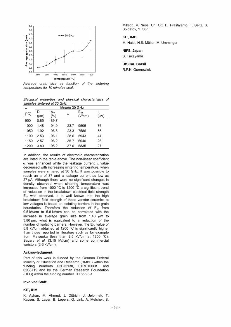
- 53 -
900 950 1000 1050 1100 1150 12000.0
0.5
1.0
1.5
2.0
2.5
3.0
3.5
4.0
4.5
5.0
5.5
Av
era
ge
gra
in s
ize
(m
)
Temperature (°C)
30 GHz
Average grain size as function of the sintering temperature for 10 minutes soak
Electrical properties and physical characteristics of samples sintered at 30 GHz.
T (°C)
Mnano 30 GHz D (μm)
ρrel (%)
EBr (V/cm)
IL (μA)
950 0.85 89.7 - - -
1000 1.48 94.9 23.7 9506 76
1050 1.92 96.6 23.3 7586 55
1100 2.53 96.1 28.6 5943 44
1150 2.57 96.2 35.7 6040 26
1200 3.80 95.2 37.0 5835 27
In addition, the results of electronic characterization are listed in the table above. The non-linear coefficient was enhanced while the leakage current IL value decreased with increasing sintering temperature, when samples were sintered at 30 GHz. It was possible to reach an of 37 and a leakage current as low as 27 μA. Although there were no significant changes in density observed when sintering temperature was increased from 1000 °C to 1200 °C a significant trend of reduction in the breakdown electrical field strength Ebr was observed. It is well known that the high breakdown field strength of those varistor ceramics at low voltages is based on isolating barriers in the grain boundaries. Therefore the reduction of Ebr from 9.5 kV/cm to 5.8 kV/cm can be correlated with the increase in average grain size from 1.48 m to 3.80 m, what is equivalent to a reduction of the number of isolating barriers. However, the EBr value of 5.8 kV/cm obtained at 1200 °C is significantly higher than those reported in literature such as for example from Matsuoka (less than 2.5 kV/cm at 1200 °C), Savary et al. (3.15 kV/cm) and some commercial varistors (2-3 kV/cm).
Acknowledgment:
Part of this work is funded by the German Federal Ministry of Education and Research (BMBF) within the funding numbers 02PJ2130, 01RC1006K, and 02S8719 and by the German Research Foundation (DFG) within the funding number TH 656/3-1.
Involved Staff:
KIT, IHM
K. Ayhan, M. Ahmed, J. Dittrich, J. Jelonnek, T. Kayser, S. Layer, B. Lepers, G. Link, A. Melcher, S.
Miksch, V. Nuss, Ch. Ott, D. Prastiyanto, T. Seitz, S. Soldatov, Y. Sun,
KIT, IMB
M. Haist, H.S. Müller, M. Umminger
NIFS, Japan
S. Takayama
UfSCar, Brasil
R.F.K. Gunnewiek

- 54 -
List of Publications
HGF Program: Fusion
Publications at cross-referenced journals:
I. Landman, S. Pestchanyi, Y. Igitkhanov, et al. (2013), Modelling of massive gas injection for ITER disruption mitigation, Journal of Nuclear Materials, Vol. 438, pp. 871-874.
I. Landman, B. Bazylev, S. Pestchanyi, et al. (2013), Radiation loads on the ITER first wall during massive gas injection, Fusion Engineering Design, Vol. 88, pp. 1682-1685.
S. Pestchanyi, I. Landman, et al. (2013), Simulation of tungsten plasma transport along magnetic field under ELM-like heat loads, Journal of Nuclear Materials, Vol. 438, pp. 459-462.
S. Pestchanyi, Y. Igitkhanov, I. Landman, et al. (2013), Analysis of energy cross-transport during MGI: JET experiments and TOKES simulations, Fusion Engineering Design, Vol. 88, pp. 1127-1131.
Y. Igitkhanov, B. Bazylev, I. Landman, et al. (2013), Applicability of Tungsten/EUROFER Blanket Module for the DEMO First Wall, Journal of Nuclear Materials, Vol. 438, pp. 440-444.
Y. Igitkhanov, B. Bazylev, I. Landman, et al. (2013), Plasma Facing Materials Lifetime in Steady-State DEMO Operation, Fusion Science & Technology, Vol. 64, pp. 245-249.
R. Schneider, et al. (2013), Efficient Parallelization of a Three Dimensional High-Order Particle-in-Cell Method for the Simulation of a 170 GHz Gyrotron Resonator, IEEE Transactions on Plasma Science, Vol. 41, pp. 87-98.
B. Bazylev, Y. Igitkhanov, et al. (2013), Modeling of the impact of runaway electrons on the ILW in JET, Journal of Nuclear Materials, pp. 237-240.
B. Bazylev, I. Landman, M. Thumm, et al. (2013), GDMT-T: Superconducting linear device for PMI studies, Fusion Science and Technology, Vol. 63, pp. 184-187.
I. Landman, S. Pestchanyi, et al. (2013), Dust generation mechanisms under powerful plasma impacts to the tungsten surfaces in ITER ELM simulation experiments, Journal of Nuclear Materials, Vol. 438, pp. 233-236.
B. Bazylev, et al. (2013), Stainless steel performance under ITER-relevant mitigated disruption photonic head loads, Journal of Nuclear Materials, Vol. 438, pp. 241-245.
R.A. Pitts, S. Carpentier, F. Escourbiac, T. Hirai, V. Komarov, S. Lisgo, A.S. Kukushkin, A. Loarte, M. Merola, Naik Sashala, R. Mitteau, M. Sugihara, B. Bazylev, P.C. Stangeby, et al. (2013), A full tungsten divertor for ITER: Physics issues and design status, Journal of Nuclear Materials, Vol. 438, pp. 48-56.
J. Jelonnek, K. Avramidis, G. Gantenbein, S. Illy, J. Jin, I. Pagonakis, T. Rzesnicki, A. Samartsev, M. Thumm, et al. (2013), Development of advanced gyrotrons at Europe, Fusion Science & Technology, Vol. 64, pp. 505-512.
G. Gantenbein, M. Thumm, et al. (2013), Aspects of steady-state operation of the Wendelstein 7-X stellarator, Plasma Physics and Controlled Fusion, Vol. 55, pp. 014006/1-6.
G. Gantenbein, W. Leonhardt, A. Samartsev, M. Schmid, et al. (2013), Absorbing coatings for high power millimeter-wave devices and matched loads, Fusion Engineering Design, Vol. 88, pp. 2510-2514.
M. Schmid, Choudhury Roy, G. Gantenbein, S. Illy, J. Jelonnek, T Rzesnicki, Samartsev, A. Schlaich, M. Thumm, et al. (2013), Recent achievements on tests of series gyrotrons for W7-X and planned extension at the KIT gyrotron test facility, Fusion Engineering Design, Vol. 88, pp. 945-949.
A. Schlaich, G. Gantenbein, J. Jelonnek, M. Thumm, et al. (2013), Transient millimeter-wave signal analysis with unambiguous RF spectrum reconstruction, IEEE Transactions on Microwave Theory and Techniques, Vol. 61, pp. 4660-4666.
G. Gantenbein, J. Jelonnek, M. Thumm, H. Hunger, A. Samartsev, M. Schmid, et al. (2013), Technical challenges in the construction of the steady-state stellarator Wendelstein 7-X, Nuclear Fusion, Vol. 53, pp. 126001/1-16.
M. Thumm, et al. (2013), Mode selection and coaxial cavity design for a 4-MW 170-GHz gyrotron, including thermal aspects, IEEE Transactions on Plasma Science, Vol. 41, pp. 853-861.
M. Thumm, et al. (2013), Microwave generation during 100 keV electron beam relaxation in GOL-3, Transaction of Fusion Science and Technology, Vol. 63, pp. 286-288.
M. Thumm, et al. (2013), Experimental and theoretical investigations of high power sub-millimeter wave emission at two-stream instability of high-current REB, Fusion Science & Technology, Vol. 63, pp. 82-87.
M. Thumm, et al. (2013), Measurement of complex permittivity of cylindrical objects in the e-plane of a rectangular waveguide, IEEE Transactions on Geoscience and Remote Sensing, Vol. 51, pp. 122-131.

- 55 -
M. Thumm, et al. (2013), Functional nanoceramics for intermediate temperature solid oxide fuel cells and oxygen separation membranes, Journal of the European Ceramic Society, Vol. 33, pp. 2241-2250.
J. Jin, M. Thumm, J. Jelonnek, et al. (2013), Vector method for synthesis of adapted phase-correcting mirrors for gyrotron output couplers, IEEE Transactions on Plasma Science, Vol. 41, pp. 2489-95.
M. Thumm, et al. (2013), Simulation of the thermophysical processes in the subterahertz imager based on a thin-film metamaterial converter, Radiophysics and Quantum Electronics, Vol. 56, pp. 20-35.
S. Illy, I. Pagonakis, et al. (2013), Collector loading of the 2-MW, 170-GHz Gyrotron for ITER in case of beam power modulation, IEEE Transcations on Plasma Science, Vol. 41, pp. 2742-7.
J. Jin, J. Jelonnek, I. Pagonakis, T. Rzesnicki, M. Thumm, et al. (2013), High-efficiency quasi-optical mode converter for a 1-MW TE32, 9-mode gyrotron, IEEE Transactions on Plasma Science, Vol. 41, pp. 2748-53.
M. Thumm, et al. (2013), First results fo the CERN resonant weakly interactiong sub-eV particle search (CROWS), Physical Review D, Vol. 88, pp. 075014/1-11.
A.V. Arzhannokov, N.S. Ginzburg, V.Yu. Zaslavsky, P.V. Kalinin, N.Yu. Peskov, A.S. Sergeev, S.L. Sinitsky, V.D. Stepanov, M. Thumm, (2013), Generation of powerful narrow-band 75-GHz radiation in a free-electron maser with two-dimensional distributed feedback, Technical Physics Letters, Vol. 39, pp. 801-804.
D. Strauss, G. Aiello, R. Chavan, S. Cirant, M. DeBaar, D. Farian, G. Gantenbein, T. Goodman, M.A. Henderson, W. Kasparek, K. Kleefeld, (2013), Preliminary design of the ITER ECH upper launcher, Fusion Engineering Design, Vol. 88, pp. 2761-2766.
A. Samartsev, G. Dammertz, G. Gantenbein, J. Jelonnek, M. Thumm, S. Illy, et al. (2013), Influence of annular beam displacement on the performance of a high power gyrotron, IEEE Transactions on Plasma Science, Vol. 41, pp. 872-878.
M. Thumm, et al. (2013), Generation of high-power sub-THz waves in magnetized turbulent electron beam plasmas, Journal of Infrared, Millimeter, and Terahertz Waves.
G. Gantenbein, S. Kern, T. Rzesnicki, A. Samartsev, et al. (2013), Reconstruction of energy distributions in electron beams on the basis of bremsstrahlung X-ray spectra, IEEE Transactions on Plasma Science, Vol. 41, pp. 2786-9.
M. Thumm, et al. (2013), Reflection of TE-on modes at open-ended oversized circular waveguide, IEEE Transactions on Antennas and Propagation, Vol. 61, pp. 2449-2456.
A. Malygin, S. Illy, I. Pagonakis, S. Kern, J. Weggen, M. Thumm, J. Jelonnek, K. Avramides, et al. (2013), Design and 3D-simulations of a 10 kw / 28 GHz gyrotron with a segmented emitter based on controlled-porosity reservoir cathodes, IEEE Transactions on Plasma Science, Vol. 41, pp. 2717-23.
M. Losert, J. Jin, T. Rzesnicki, et al. (2013), RF beam parameter measurements of quasi-optical mode converters in the mW range, IEEE Transactions on Plasma Science, Vol. 41, pp. 628-632.
P.A. Bagryansky, S.P. Demin, E.D. Gospodchikov, Y.V. Kovalenko, V.I. Malygin, M. Thumm, et al. (2013), ECR heating system for the gas dynamic trap, Transcations of Fusion Science and Technology, Vol. 63, pp. 40-45.
B.R. Chimitov, K.V. Zherikova, A.N. Mikheev, G.I. Zharkova, N.B. Morozova, I.K. Igumenov, A.V. Arzhannikov, M. Thumm, et al. (2013), Synthesis of ruthenium(III) and rohodium(III) tris-acetylacetonates and palladium(II) bis-ketoiminate using microwave heating, Russian Chemical Bulletin, Vol. 61, pp. 2236-2242.
Other publications:
Y. Igitkhanov, B. Bazylev, I. Landman, R. Fetzer, et al. ,"Design Strategy for the PFC in DEMO Reactor," in KIT Scientific Report, No.7637, 2013.
J. Jelonnek, "Annual Report 2012, IHM," in KIT Scientific Report, No.7643, 2013.
M. Thumm, "State-of-the Art of high power gyro-devices and free electron masers," in KIT Scientific Report, No.7641, 2013.
Choudhury Roy, M. Thumm, "On the influence of B-field shape variations on gyrotron spurious oscillations," in KIT Scientific Report, No.7640, 2013, pp. 175-180.
A. Schlaich, G. Gantenbein, J. Jelonnek, M. Thumm, "Neuartige Millimeterwellen-Spektraldiagnostik am IHM," in KIT Scientific Report 7640, 2013, pp. 169-174.
S. Pestchanyi, I. Landman, et al., (2013), Simulation of dust production from tungsten armour using PEGASUS-3D code, International Conference on Fusion Reactor Materials.
S. Pestchanyi, I. Landman, et al., (2013), Optimization of MGI in JET using TOKES code, International Symposium on Fusion Nuclear Technology.

- 56 -
G. Gantenbein, J. Jelonnek, M. Thumm, et al., (2013), ECRH and W7-X, an intriguing pair, 20th Topical Conf. on Radio Frequency Power in Plasmas.
M. Thumm, D. Wagner, E. DeRijk, W. Bongers, W. Kasparek, F. Leuterer, A. Macor, J.-Ph. Ansermet, F. Monaco, M. Münich, H. Schütz, J. Stober, Brand v.d., A. v.Bieren, (2013), Multi-frequency notch filters and corrugated 200 to 400 GHz waveguide components manufactured by stacked ring technology, Terahertz Science and Technology, Vol. 6, pp. 212-222.
M. Thumm, et al., "Components for remote sensing of asteroids and dense plasmas," in 25th Joint Russian-German Workshop, Karlsruhe, Germany, 2013.
Y. Igitkhanov, B. Bazylev, R. Fetzer, I. Landman, et al., "Design Strategy for the PFC in DEMO Reactor," in 11th Internat. Symp. on Fusion Nuclear Technology, Barcelona, Spain, 2013.
Y. Igitkhanov, B. Bazylev, et al., "Energy and particle inpact on W surface for the case of repetitive ELMS and RE electrons in DEMO plasmas," in SOFE, San Francisco, USA, 2013.
B. Bazylev, I. Landman, et al., "Tungsten damage and melt losses under the plasma accelerator exposures in ITER ELM conditions," in ICPFM, 2013, p. A043.
B. Bazylev, Y. Igitkhanov, et al., "Erosion of DEMO first wall W armour under runaway elctron impact," in ICPFM, 2013, p. A122.
J. Jelonnek, G. Gantenbein, J. Jin, I. Pagonakis, T. Rzesnicki, M. Thumm, K. Avramidis, et al., "From series production of gyrotrons for W7-X towards EU-1MW gyrotrons for ITER," in PPPS (ICOPS ), San Francisco, USA, 2013.
A. Schlaich, G. Gantenbein, J. Jelonnek, M. Thumm, et al., "Time-dependent analysis of gyrotron RF output spectrum," in 25th Joint Russian-German Workshop, Karlsruhe, Germany, 2013.
A. Schlaich, J. Jelonnek, M. Thumm, et al., "Millimeter-wave time-domain spectrum analysis system with unambiguous RF spectrum reconstruction," in IEEE International Microwave Symposium (IMS), Seattle, USA, 2013.
M. Cordova, K. Avramidis, S. Illy, J. Jelonnek, C. Wu, et al., (2013), Thermo-mechanical study of the cavity deformation in the case of the 1 MW, 140 GHz gyrotron for W7-X, Workshop on RF Heating Technology of Fusion Plasmas.
J. Jelonnek, K. Avramidis, J. Franck, G. Gantenbein, S. Illy, I.Gr. Pagonakis, T. Rzesnicki, A. Samartsev, A. Schlaich, M. Schmid, M. Thumm, J. Zhang, et al., (2013), Status, progress and future plans of EC RF source development at KIT, Workshop on RF Heating Technology of Fusion Plasmas.
M. Thumm, K. Avramidis, G. Gantenbein, J. Jelonnek, J. Jin, I. Pagonakis, T. Rzesnicki, M. Schmid, et al., (2013), Series production of 1 MW, 140 GHz, CW gyrotrons for W7-X leading to EU-1 MW, 170 GHz, CW gyrotrons for ITER, Workshop on Vacuum Electronics Devices and Applications (VEDA Kolleg).
KIT-IHM W7-Team, "Integrated commissioning of ECRH for W7-X," in IRMMW, Mainz, Germany, 2013.
ECRH W7-X, "W7-X commissioning - required enhancement of the ECRH control system," in 25th Joint Russian-German Workshop, Karlsruhe, Germany, 2013.
I. Pagonakis, G. Gantenbein, J. Jelonnek, J. Jin, S. Illy, S. Kern, T. Rzesnicki, M. Thumm, K. Avramides, et al., "Design of the EU-1MW Gyrotron for ITER," in IVEC, Paris, France, 2013.
G. Gantenbein, G. Dammertz, J. Jelonnek, M. Losert, A. Samartsev, A. Schlaich, M. Thumm, et al., "Operation of a step-frequency tunable gyrotron with a diamond brewster anlge output window," in IVEC, Paris, France, 2013.
A. Schlaich, G. Gantenbein, J. Jelonnek, A. Samartsev, M. Thumm, et al., "Study of RF output window arc event in a megawatt class 140 GHz gyrotron," in PPPS (ICOPS), San Francisco, USA, 2013.
M. Thumm, "Development of investigation of mm and sub-mm waves at LPIMTR of NSU," in All-russian Seminar, Nizhny Novgorod, 2013.
M. Thumm, "Synchronous generation of 4-mm radiation pulses in two-channel FEM," in All-russian Seminar, Nizhny Novgorod, 2013.
T. Rzesnicki, G. Gantenbein, S. Illy, J. Jelonnek, J. Jin, I. Pagonakis, A. Samartsev, A. Schlaich, M. Thumm, et al., "2 MW, 170 GHz coaxial-cavity short-pulse gyrotron - recent experimental results with the modified gyrotron setup," in 25th Joint Russian-German Workshop, Karlsruhe, Germany, 2013.
S. Illy, I. Pagonakis, et al., "Thermomechanical impact of gyrotron power modulation on the collector of a 2 MW, 170 GHz gyrotron," in 25th Joint Russian-German Workshop, Karlsruhe, Germany, 2013.

- 57 -
J. Zhang, S. Illy, I. Pagonakis, J. Jelonnek, et al., "Effect of emitter surface roughness in gyrotron," in 25th Joint Russian-German Workshop, Karlsruhe, Germany, 2013.
K. Avramidis, I. Pagonakis, et al., "The code-package EURIDICE for gyrotron interaction simulations and cavity design," in 25th Joint Russian-German Workshop, Karlsruhe, Germany, 2013.
G. Gantenbein, K. Avramidis, J. Franck, S. Illy, J. Jelonnek, J. Jin, A. Malygin, I. Pagonakis, T. Rzesnicki, A. Samartsev, A. Schlaich, M. Thumm, J. Zhang, et al., "Gyrotron investigations and developments for W7-X, ITER and towards DEMO," in 25th Joint Russian-German Workshop, Karlsruhe, Germany, 2013.
J. Frank, K. Avramidis, S. Illy, et al., "Mode selection for 240-300 GHz gyrotrons," in 25th Joint Russian-German Workshop, Karlsruhe, Germany, 2013.
J. Zhang, S. Illy, I. Pagonakis, J. Jelonnek, et al., "Preliminary study on the effects of emitter surface roughness on gyrotron electron beam quality," in IRMMW, Mainz, Germanz, 2013.
J. Jelonnek, K. Avramidis, J. Franck, G. Gantenbein, S. Illy, J. Jin, A. Malygin, I. Pagonakis, T. Rzesnicki, A. Samartsev, A. Schlaich, M. Schmid, M. Thumm, J. Zhang, J. Zhang, et al., "KIT gyrotron development for future fusion applications," in IRMMW, Mainz, Germany, 2013.
M. Thumm, et al., "Sub-THz waves generation by magnetized plasma with strong turbulence driven by high-current REB," in IRMMW, Mainz, Germany, 2013.
I. Pagonakis, K. Avramidis, G. Gantenbein, S. Illy, J. Jelonnek, J. Jin, T. Rzesnicki, M. Thumm, et al., "The 1 MW 170 GHz conventional cavity gyrotron for ITER," in 25th Joint Russian-German Workshop, Karlsruhe, Germany, 2013.
M. Thumm, et al., "High-power sub-THz wave generation at two-stream instability of high-current electron beam in magnetized plasma (experimentel and theoretical investigations) beam-plasma system for sub-THz generation," in 25th Joint Russian-German Workshop, Karlsruhe, Germany, 2013.
M. Thumm, et al., "High-power sub-THz wave generation during electron beam transportation through magnetized plasmas," in PPPS (ICOPS), San Francisco, USA, 2013.
K.A. Avramidis, I. Pagonakis, et al., "Numerical investigation on the effects of electron beam misalignment on beam-wave interaction in a high-power coaxial gyrotron," in IRMMW, Mainz, Germany, 2013.
J. Jelonnek, (2013), Overview on IHM research topics and plans (plenary introduction), NUDT.
J. Jelonnek, (2013), Introduction to gyrotrons and related research at IHM (Part 1), NUDT.
J. Jelonnek, (2013), Introduction to gyrotrons and related research at IHM (Part 2), NUDT.
J. Jelonnek, (2013), Zukunft Fusion: Hochleistungsmikrowellentechnik im Brennpunkt der Plasmaphysik, VDE Hochschulgruppe.
T. Rzesnicki, G. Gantenbein, S. Illy, J. Jelonnek, J. Jin, I. Pagonakis, A. Schlaich, M. Thumm, et al., "2 MW, 170 GHz coaxial-cavity short-pulse gyrotron - investigations on electron beam instabilities and parasitic oscillations," in IRMMW, Mainz, Germany, 2013.
T. Rzesnicki, G. Gantenbein, S. Illy, J. Jelonnek, J. Jin, I.Gr. Pagonakis, et al., (2013), 2 MW, 170 GHz coaxial-cavity short-pulse gyrotron - investigations on electron beam instabilities and parasitic oscillations -, Workshop on RF Heating Technology of Fusion Plasmas.
I.Gr. Avramidis, G. Gantenbein, J. Jelonnek, J. Jin, S. Illy, T. Rzesnicki, M. Thumm, et al., (2013), The status of EU-1 MW gyrotron for ITER, Workshop on RF Heating Technology of Fusion Plasmas.
S. Illy, J. Jelonnek, et al., (2013), Estimation of collector lifetime for the EU 1 MW, 170 GHz CW gyrotron for ITER using transient FE-analysis, Workshop on RF Heating Technology of Fusion Plasmas.
T. Rzesnicki, G. Gantenbein, et al., (2013), Overview of a multi-code analysis of high power 170 GHz beams in terms of the HEm,n modes, Workshop on RF Heating Technology of Fusion Plasmas.
K. Avramidis, G. Gantenbein, J. Jelonnek, I.Gr. Pagonakis, et al., (2013), Status of the ITER EC H&CD system, Workshop on RF Heating Technology of Fusion Plasmas.
Samartsev, G. Gantenbein, J. Jelonnek, S. Illy, M. Thumm, et al., (2013), Experimental, numerical studies on eccentricity of annular electron beam in 1 MW gyrotron cavity, Workshop on RF Heating Technology of Fusion Plasmas.
Choudhury Roy, M. Thumm, (2013), Investigations of dynamic after cavity interaction using uniform magnetic field, adiabatic approximation, Workshop on Vacuum Electronics Devices and Applications (VEDA Kolleg).
M. Thumm, (2013), Introduction to energy generation and heating in nuclear fusion plasmas, Humboldt Colloquium, Indian Institute of Technology.

- 58 -
M. Thumm, et al., (2013), Worldwide state-fo-the-art of high power gyrotrons for ECH & CD in thermonuclear fusion experiments, Inaugural Conf. of the Cooperative Innovation Centre of THz Science.
M. Thumm, D. Wagner, E. DeRijk, W. Bongers, W. Kasparek, F. Leuterer, A. Macor, F. Monaco, M. Münich, M. Schütz, J. Stober, den van and von Bieren, (2013), Multi-frequency notch filters and corrugated 500 to 750 GHz waveguide components manufactured by stacked ring technology, 4th SICAST.
M. Thumm, "Ka-band groundstation antenna aspects for deep space telecommunication and radar," in 7th European Conference on Antennas and Propagation, Göteburg, Sweden, 2013.
M. Thumm, et al., "Mode purity estimation of the gyrotron RF beam," in IRMMW, Mainz, Germany, 2013.
M. Thumm, (2013), Lecture series on gyrotrons, No. 1, principle of gyrotron, Seminar, Institute of Electronics of the Chinese Academy of Sciences.
M. Thumm, (2013), Lecture series on gyrotrons, No. 2, electron gun, beam tunnel, magnets, Seminar, Institute of Electronics of the Chinese Academy of Sciences.
M. Thumm, (2013), Lecture series on gyrotrons, No. 3, cavity, uptaper, q.o.-mode converter, collector, Seminar, Institute of Electronics of the Chinese Academy of Sciences.
M. Thumm, (2013), Lecture series on gyrotrons, No. 4, RF window, state of the art of high power gyrotrons, Seminar, Institute of Electronics of the Chinese Academy of Sciences.
M. Thumm, (2013), Lecture series on gyrotrons, No. 5, W7-X gyrotron, HV power supply, Seminar, Institute of Electronics of the Chinese Academy of Sciences.
M. Thumm, (2013), Lecture series on gyrotrons, No. 6, coaxial cavity gyrotrons, Seminar, Institute of Electronics of the Chinese Academy of Sciences.
M. Thumm, (2013), Lecture series on gyrotrons, No. 7, frequency tunable gyrotrons, technology gyrotrons, Seminar, Institute of Electronics of the Chinese Academy of Sciences.
M. Thumm, (2013), Lecture series on gyrotrons, No. 8, gyrotrons for spectroscopy, gyro-amplifiers, Seminar, Institute of Electronics of the Chinese Academy of Sciences.
M. Thumm, (2013), Lecture series on high-power mm-wave transmission, No. 1, mode conversion in overmoded waveguides , Seminar, Institute of Electronics of the Chinese Academy of Sciences.
M. Thumm, (2013), Lecture series on high-power mm-wave transmission, No. 2, HE11 mode, beam waveguides , Seminar, Institute of Electronics of the Chinese Academy of Sciences.
M. Thumm, (2013), Lecture series on high-power mm-wave transmission, No. 3, quasi-optical mode converters, Seminar, Institute of Electronics of the Chinese Academy of Sciences.
M. Thumm, (2013), Lecture series on high-power mm-wave transmission, No. 4, W7-X ECRH system, Seminar, Institute of Electronics of the Chinese Academy of Sciences.
M. Thumm, J. Jelonnek, G. Gantenbein, S. Illy, J. Jin, W. Leonhardt, I. Pagonakis, A. Roy-Choudhury, T. Rzesnicki, A. Samartsev, A. Schlaich, M. Schmid, et al., "Status of high-power fusion gyrotron development at KIT," in Symp. on Terahertz Gyrotrons, Fukui, Japan, 2013.
A. Malygin, S. Illy, I. Pagonakis, K. Avramides, M. Thumm, J. Jelonnek, D. D'Andrea, et al., "Analysis of mode competition in 10 kW / 28 GHz gyrotron," in IVEC, Paris, France, 2013.
M. Thumm, "Generation of terahertz radiation in beam-plasma interaction experiments at the GOL-3 facility," in All-russian Seminar, Nizhny Novgorod, Russia, 2013.
A. Malygin, S. Illy, I. Pagonakis, K. Avramides, M. Thumm, J. Jelonnek, et al., "Analysis of mode competition in 10 kW / 28 GHz gyrotron," in 25th Joint Russian-German Workshop, Karlsruhe, Germany, 2013.
G. Gantenbein, A. Samartsev, J. Jelonnek, A. Schlaich, M. Thumm, et al., "Operation of a step-frequency tunable gyrotron with a diamond brewster angle output window," in 25th Joint Russian-German Workshop, Karlsruhe, Germany, 2013.
A. Samartsev, G. Gantenbein, J. Jelonnek, M. Losert, A. Schlaich, M. Thumm, et al., "Numerical and experimental study of electron beam axial misalignment on the performance of gyrotron," in 25th Joint Russian-German Workshop, Karlsruhe, Germany, 2013.
A. Samartsev, G. Gantenbein, J. Jelonnek, A. Schlaich, M. Thumm, et al., "First operation of a D-band megawatt gyrotron with elliptically brazed diamond window," in IRMMW, Mainz, Germany, 2013.
M. Thumm, et al., "Progress in the development of multifrequency notch filters," in 25th Joint Russian-German Workshop, Karlsruhe, Germany, 2013.

- 59 -
G. Gantenbein, M. Thumm, et al., "The ECRH system for ADEX upgrade - status and plans," in 25th Joint Russian-German Workshop, Karlsruhe, Germany, 2013.
A. Schlaich, G. Gantenbein, J. Jelonnek, M. Thumm, et al., "Simulations of high power gyrotron operation during Window Arc," in IRMMW, Mainz, Germany, 2013.
M. Thumm, et al., "Recent advances in the gyrotron development activities worldwide," in SOFE, San Francisco, USA, 2013.
A. Malygin, et al., "Advanced CPR cathode research," in IVEC, Paris, France, 2013.
M. Thumm, (2013), Attenuation and mode conversion in overmoded waveguides, NUDT.
M. Thumm, (2013), Diagnostics and adiabatic mode converters in overmoded waveguides, NUDT.
M. Thumm, (2013), Mode converters and components in overmoded waveguides I, NUDT.
M. Thumm, (2013), Mode converters and components in overmoded waveguides II, NUDT.
M. Thumm, (2013), High-power millimeter wave quasi-optical components and mode converters, NUDT.
M. Thumm, (2013), Lecture Series on Gyrotrons, No. 1, Principle of gyrotron, Seminar, Korean Electrotechnology Res. Institute.
M. Thumm, (2013), Lecture series on gyrotrons, No. 2, electron gun, beam tunnel, magnets, Seminar, Korean Electrotechnology Res. Institute.
M. Thumm, (2013), Lecture series on gyrotrons, No. 3, cavity, uptaper, Q.O.-mode converter, collector, Seminar, Korean Electrotechnology Res. Institute.
M. Thumm, (2013), Lecture series on gyrotrons, No. 4, RF window, state of the art of high power gyrotrons, Seminar, Korean Electrotechnology Res. Institute.
M. Thumm, (2013), Lecture series on gyrotrons, No. 5, W7-X gyrotron, HV power supply, Seminar, Korean Electrotechnology Res. Institute.
M. Thumm, (2013), Lecture series on gyrotrons, No. 6, coaxial cavity gyrotrons, Seminar, Korean Electrotechnology Res. Institute.
M. Thumm, (2013), Lecture series on gyrotrons, No. 7, Frequency tunable gyrotrons, technology gyrotrons, Seminar, Korean Electrotechnology Res. Institute.
M. Thumm, (2013), Lecture series on gyrotrons, No. 8, gyrotrons for spectroscopy, gyro-amplifiers, Seminar, Korean Electrotechnology Res. Institute.
J. Jelonnek, (2013), Research in pulsed power and microwave technology at IHM, Beijing Vacuum Electronics Research Inst. (BVERI).
J. Jelonnek, (2013), Research in pulsed power and microwave technology at IHM, Institute of Electronics, Chinese Academy of Sciences (IECAS).
J. Jelonnek, M. Thumm, G. Gantenbein, et al., (2013), The ASDEX upgrade multi-frequency ECRH system status and plans, Workshop on RF Heating Technology of Fusion Plasmas.
M. Thumm, et al., (2013), Millimeter-wave gyro-amplifier RADAR systems, Seminar at IEEE-MTT Student Chapter of Indian Institute of Technology.
M. Thumm, et al., (2013), Recent advances in the worldwide development of gyrotrons for fusion plasma research, CSIR - Central Electronics Engineering Research Institute.
J. Jelonnek, M. Thumm, et al., "A 1.0-1.3 MW CW, 238 GHz conventional cavity gyrotron," in IRMMW, Mainz, Germany, 2013.
M. Thumm, et al., "Multifrequency notch filter for sub-THz applications based on photonic bandgaps in corrugated circular waveguides," in IRMMW, Mainz, Germany, 2013.
HGF Program: NUKLEAR
Publications at cross-referenced journals:
R. Dagan, A. Jianu, G. Rimpault, A. Weisenburger, M. Schikorr, (2013), The consequences of a sharp temperature change in the fuel pins of an accelerator-driven subcritical system, Nuclear Technology, Vol. 184, pp. 210-216.
A. Weisenburger, A. Jianu, M. DelGiacco, R. Fetzer, A. Heinzel, G. Müller, et al. (2013), Material selection for lead cooled fast reactors, Revue generale du nucléaire.
R. Fetzer, A. Weisenburger, G. Müller, et al. (2013), Surface layer dynamics during E-beam treatment, IEEE Transactions on Plasma Science, Vol. 41, pp. 2858-2862.
A. Heinzel, G. Müller, A. Weisenburger, et al. (2013), Behavior of welds in liquid lead containing 10-6 wt% and 10-8 wt% oxygen, Journal of Nuclear Materials, Vol. 437, pp. 116-121.
A. Weisenburger, A. Jianu, R. Fetzer, A. Heinzel, M. DelGiacco, W. An, G. Müller, et al. (2013), Oxide scales formed on Fe-Cr-Al-based model alloys exposed to oxygen containing molten lead, Journal of Nuclear Materials, Vol. 437, pp. 282-292.

- 60 -
G. Müller, V. Engelko, et al. (2013), Microsecond intense electron beams for industrial applications, IEEE Transactions on Plasma Science, Vol. 41, pp. 2769-2773.
W. An, G. Müller, et al. (2013), Numerical simulation of the plasma generated by the interaction high-current electron beam with Al target, Journal of Applied Physics, Vol. 113, pp. 123302/1-6.
M. DelGiacco, A. Weisenburger, G. Müller, et al. (2013), Fretting corrosion for lead alloy cooled ADS, Journal of Nucl. Mat..
Other publications:
A. Weisenburger, et al. (2013), Advanced corrosion barriers and fretting issues in liquid PB alloys, Abschlusssymposium des EU Projetes GETMAT.
R. Fetzer, W. An, A. Weisenburger, G. Müller, et al. "GESA facility with fast in-situ diagnostics for investigation of electron beam interaction with metal targets," in PFMC-Konferenz, Aachen, Germany, 2013.
M. DelGiacco, A. Weisenburger, G. Müller, et al. "Freeting of fuel cladding materials for Pb cooled fast reactors - long term prediction using freeting maps," in Internat. Conf. on Nuclear Engineering (ICONE 21), Chengdu, China, 2013.
A. Weisenburger, G. Müller, M. DelGiacco, R. Fetzer, A. Heinzel, A. Jianu, et al. "Materials, corrosion and corrosion protection for lead alloy cooled nuclear reactors," in Conf. "Heavy Liquid Metal Coolants in Nuclear Technologies" (HLMC), Obninsk, Russia, 2013.
A. Heinzel, A. Jianu, A. Weisenburger, G. Müller, R. Fetzer, et al. "Corrosion behaviour of Fe-Cr-Al model alloys exposed at 400-600 C in oxygen containing molten lead," in Jahrestagung, Kerntechnik, Berlin, Germany, 2013.
A. Weisenburger, et al. (2013), Material technology for LFR - corrosion, corrosion protection and Pb-chemistry, LEADER/ELECTRA Safety Workshop at JRC.
G. Müller, A. Jianu, M. DelGiacco, R. Fetzer, A. Heinzel, A. Weisenburger, et al. "Selection and challenges for LFR reactor materials," in Jahrestagung, Kerntechnik, Berlin, Germany, 2013.
G. Müller, A. Jianu, A. Heinzel, A. Weisenburger, et al. "Fabrication process and basic investigation of 9 and 12 Cr ODS steel," in EUROMAT, Sevilla, Spain, 2013.
A. Jianu, A. Weisenburger, R. Fetzer, A. Heinzel, G. Müller, et al. "FeCrAI-based coatings for improving corrosion resistance of steels exposed to molten Pb," in EUROCORR, Estoril, Portugal, 2013.
A. Jianu, G. Mueller, R. Fetzer, A. Heinzel, A. Weisenburger, et al. "Critical Al content required to form a protective alumina layer on Fe-Cr-Al alloys exposed to oxygen-containting molten lead," in EUROMAT, Sevilla, Spain, 2013.
W. An, G. Mueller, S. Illy, et al. "Measurement and simulations of electron beam precession in Gesa 1 and Gesa 2 facilities," in PPPS (ICOPS), San Francisco, USA, 2013.
R. Fetzer, W. An, A. Weisenburger, G. Müller, et al. "Target surface layer dynamics during application of intense electron beams," in PPPS (ICOPS), San Francisco, USA, 2013.
A. Weisenburger, A. Jianu, M. DelGiacco, R. Fetzer, A. Heinzel, G. Müller, et al. "Materials for ALFRED and ELER - selection and challenges," in Internat. Conference on Fast Reactors, Paris, France, 2013.
A. Weisenburger, W. An, R. Fetzer, G. Müller, et al. "Beam homogeneity measurement of a radial converging E-beam facility," in PPPS (ICOPS), San Francisco, USA, 2013.
C. Schultheiss, et al. (2013), Momentum and energy of a mass consisting of confined photons and resulting quantum mechanical implications, Advanced Studies in Theoretical Physics, Vol. 7, pp. 555-583.
G. Müller, et al. (2013), Gepulste Elektronenstrahlen und ihre Anwendung in der Materialsprozesstechnik, Fakultätskolloquium, KIT-CS (HSI).
A. Jianu, et al. "Challenges related to the use of liquid metal and molten salt coolants in advanced reactors," in IAEA-TECDOC-1696, 2013.
HGF Program: REUN
Publications at cross-referenced journals:
M. Thumm, (2013), Crystalline products of tolbutamide decomposition in water after microwave treatment, CrystEngComm, Vol. 15, pp. 3582-3586.
M. Thumm, (2013), Measurment of complex permittivity of cylindrical objects in the E-plane of a rectangualr waveguide, IEEE Transactions on Geoscience and Remote Sensing, Vol. 51, pp. 122-131.

- 61 -
Other publications:
D. Prastiyanto, G. Link, et al., "Temperature dependent dielectric measurements at 2.45 GHz," in Internat. Conf. Unnees Conservation, Semarang, Indonesia, 2013.
G. Link, T. Kayser, A. Melcher, D. Prastiyanto, S. Soldatov, J. Jelonnek, et al., "Microwave materials processing at the Karlsruhe Institute of Technology," in Internat. Conf. Unnees Conservation,, Semarang, Indonesia, 2013.
T. Kayser, A. Melcher, et al., "Experimentelle Untersuchungen der Beheizung eines Festbettreaktors durch Mikrowellen," in Jahrestreffen Hochtemperatur-technik, Oberhausen, Germany, 2013.
A. Melcher, T. Kayser, S. Soldatov, G. Link, J. Jelonnek, et al., "Thermoelastic model for microwave ablation of concrete," in Seminar on Computer Modeling (CIMS), Padova, Italy, 2013.
M. Thumm, J. Jelonnek, G. Link, M. Mahmoud, S Takayama, et al., "Status of high-temperature microwave materials processing at KIT," in Symp. on Terahertz Gyrotrons, Fukui, Japan, 2013.
Mahmoud Morsi, G. Link, J. Jelonnek, M. Thumm, et al., "Sintering of copper metal powders using 30 GHz microwave processing," in 25th Joint Russian-German Workshop, Karlsruhe, Germany, 2013.
M. Thumm, et al., "Microstructured frequency selective quasi-optical components for subterahertz and terahertz applications," in IRMMW, Mainz, Germany, 2013.
T. Kayser, S. Soldatov, A. Melcher, G. Link, J. Jelonnek, et al., "A microwave applicator for high homogeneous high temperature heating of catalysts," in Internat. Microwave Symposium (IMS), Seattle, USA, 2013.
S. Soldatov, T. Kayser, G. Link, T. Seitz, S. Layer, J. Jelonnek, et al., "Microwave cavity perturbation technique for high-temperature dielectric measurements," in Internat. Microwave Symposium (IMS), Seattle, USA, 2013.
Mahmoud Morsi, et al., (2013), High frequency microwave crystallization of glass, 25th Joint Russian-German Workshop.
D. Prastiyanto, G. Link, M. Thumm, J. Jelonnek, et al., "Temperature dependent measurements of dielectric materials at 2.45 GHz," in KIT Scientific Report 7640, 2013, pp. 163-168.
S. Soldatov, T. Kayser, G. Link, T. Seitz, S. Layer, J. Jelonnek, et al., "Temperature dependent dielectric measurements based on the microwave cavity perturbation technique," in 14th Internat. Conference on Microwave and High Frequency Heating, Nottingham, UK, 2013, pp. 297-300.
B. Lepers, S. Soldatov, G. Link, J. Jelonnek, et al., "A thermo elastic model for microwave ablation of concrete," in 14th Internat. Conference on Microwave and High Frequency Heating, Nottingham, UK, 2013, pp. 217-220.
G. Link, T. Kayser, J. Jelonnek, et al., "Microwave assisted pultrusion of carbon fibre reinforced polymers," in 14th Internat. Conference on Microwave and High Frequency Heating, Nottingham, UK, 2013, pp. 146-150.
HGF Program: EE
Publications at cross-referenced journals:
M. Sack, et al., (2013), Cell membrane electroporation - Part 3. The equipment, IEEE Electrical Insulation Magazine.
M. Sack, G. Müller, et al., (2013), Design considerations for a fast stacked-MOSFET Switch, IEEE Transactions on Plasma Science, Vol. 41, pp. 2630-2636.
L. Wegner, (2013), Cation selectivity of the plasma membrane of tobacco protoplasts in the electroporated state, Biochimica et Biophysica Acta – Biomembraned, 1828, pp. 1973-1981.
L. Wegner, W. Frey, et al., (2013), A critical evaluation of whole cell patch clamp studies on electroporation using the voltage sensitive dye ANNINE-6, Bioelectrochemistry, Vol. 92, pp. 42-46.
M. Sack, et al., (2013), Hochspannung im Weinkeller, AGRO Journal, Vol. 5.
C. Eing, W. Frey, et al., (2013), Nanosecond electric pulses affect a plant kinesin at the plasma membrane, Journal of Membrane Biology, Vol. 246, pp. 927-938.
R. Sträßner, C. Eing, M. Göttel, C. Gusbeth, W. Frey, et al., (2013), Monitoring of pulsed electric field-induced abiotic stress on microalgae by chlorophyll fluorescence diagnostic, IEEE Transactions on Plasma Science, Vol. 41, pp. 2951-2958.
C. Eing, M. Göttel, R. Strässner, C. Gusbeth, W. Frey, et al., (2013), Pulsed electric field treatment of microalgae - benefits for microalgae biomass processing, IEEE Transactions on Plasma Science, Vol. 41, pp. 2901-2907.

- 62 -
C. Eing, M. Göttel, R. Strässner, C. Gusbeth, W. Frey, et al., (2013), Pulsed electric field treatment of microalgae - benefits for microalgae biomass processing, IEEE Transactions on Plasma Science, Vol. 41, pp. 2901-2907.
W. Frey, W. Jiang, M. Sack, et al., (2013), Special issue for selected papers from EAPPC/BEAMS 2012 (Editorial), IEEE Transactions on Plasma Science, Vol. 41, p. 2579.
W. Frey, C. Gusbeth, T. Schwartz, (2013), Invitation of pseudomonas putida by pulsed electric field treatment parameters and inactivation efficiency in the short-puls range, Journal of Membrane Biology.
Other publications:
C. Gusbeth, W. Frey, et al., "Bacterial decontamination of wastewater by pulsed electric field treatment," in Symp. Bioelectrochemistry, Bochum, Germany, 2013.
W. Frey, C. Eing, M. Göttel, C. Gusbeth, R. Strässner, et al., "PEF-processing of microalgae for cell component extraction," in PPPS (ICOPS), San Francisco, USA, 2013.
M. Sack, G. Müller, et al., "Set-up and testing of a fast stacked-MOSFER switch," in PPPS (ICOPS), San Francisco, USA, 2013.
C. Gusbeth, W. Frey, M. Göttel, C. Eing, et al., "Boost of algae growth by ultra short pulsed electric field treatment," in PPPS (ICOPS), San Francisco, USA, 2013.
C. Eing, M. Göttel, C. Gusbeth, R. Strässner, W. Frey, et al., "Improved lipid extraction from microalgae after pulsed electric field treatment," in Bioelectromagnetic Conf., Thessaloniki, Greece, 2013.
M. Göttel, C. Eing, C. Gusbeth, R. Strässner, W. Frey, (2013), Pulsed electric field assisted extraction of intracellular valuables from microalgae, Algal Research.
M. Sack, G. Müller, et al., "Fast stacked MOSFET switch for a blumlein generator," in Bioelectrics Symposium, Karlsruhe, Germany, 2013.
M. Göttel, C. Eing, C. Gusbeth, W. Frey, et al., "Electroporation of the green microalgae auxenochllorella protothecoides," in Internat. Scientific Workshop and Postgraduate Course, Ljubljana, Slowenien, 2013.
L. Wegner, A. Silve, W. Frey, et al., (2013), Electroporation of DC3-F cells is a two-step process, Bioelectrics Symposium.
A. Silve, S. Rocke, W. Frey, et al., (2013), Spectral analysis of the voltage sensitive dye ANNINE-6 and consequences on the calibration, Bioelectrics Symposium.
A. Silve, S. Rocke, R. Strässner, M. Sack, W. Frey, et al., (2013), Correlation between transmembrane voltage measurement and permeabilisation experiments on DC3F cells submitted to 100 electric pulses, Bioelectrics Symposium.
A. Silve, et al., (2013), Numerical studies of electroporation: influence of the pulse duration and cell shape on the degrr of permeabilization and PI uptake, Bioelectrics Symposium.
M. Göttel, C. Eing, R. Wüstner, W. Frey, et al., (2013), Pulsed electric field (PEF) treatment of fresh-water microalgae, Bioelectrics Symposium.
C. Eing, M. Göttel, R. Strässner, C. Gusbeth, W. Frey, et al., (2013), Improved lipid extraction from microalgae after pulsed electric field treatment, Bioelectrics Symposium.
C. Gusbeth, W. Frey, et al., (2013), Bacterial decontamination of hospital wastewater by pulsed electric field treatment, Bioelectrics Symposium.
R. Strässner, C. Eing, M. Göttel, C. Gusbeth, A. Silve, W. Frey, et al., (2013), Application of a photosynthetic activity diagnostic to monitor nanosecond pulsed electric field stress imposed on microalgae organelles, Bioelectrics Symposium.
M. Sack, et al., (2013), Pulsed-power system desin, iFOOD-Konferenz.
W. Frey, M. Göttel, C. Eing, C. Gusbeth, Pulsed electric field treatment of microalegae: benefits fort he extraction of cell ingredients, Innovation Food Conference (iFOOD 2013).
HGF Program: TIG EE
Publications at cross-referenced journals:
R. Strässner, C. Eing, M. Göttel, C. Gusbeth, W. Frey, et al., (2013), Monitoring of pulsed electric field induced abiotic stress on microalge by chlorophyll fluorescence diagnostic, IEEE Transactions on Plasma Science, Vol. 41, pp. 2951-2958.

- 63 -
HGF Program: NANOMIKRO
Other publications:
M. Morsi, Link, M. Thumm, et al., (2013), In situ dilatometry and electrical resistivity measurements of copper metal powder compacts during high frequency mircowave sintering, Materials Science & Technology (MS&T'13).
G. Link, J. Jelonnek, et al., "The influence of microwaves on residual impurities during pig iron production," in 14th Internat. Conference on Microwave and High Frequecy Heating, Nottingham, Nottingham, UK, 2013, pp. 65-68.