institute for steel construction – leibniz university of hannover 2. phd seminar on wind energy in...
TRANSCRIPT
Institute for Steel Construction – Leibniz University of Hannover2. PhD Seminar on Wind Energy in Europe
October 4th and 5th 2006 at Risø National Laboratory, Roskilde, Denmark
Influences on the fatigue of offshore structures at the example of the FINO 1
research platform
Cord Böker

Institute for Steel Construction – Leibniz University of Hannover2. PhD Seminar on Wind Energy in Europe
October 4th and 5th 2006 at Risø National Laboratory, Roskilde, Denmark
Agenda
• Introduction
• Influence of wave directions • Structural modeling

Institute for Steel Construction – Leibniz University of Hannover2. PhD Seminar on Wind Energy in Europe
October 4th and 5th 2006 at Risø National Laboratory, Roskilde, Denmark
Introduction
• Joint research project GIGAWINDplus:Validation and improvement of design methods and tools for support structures of Offshore Wind turbines
• Focusing on fatigue• Measurement data from the research platform FINO 1
strain gages at 11 locations
• Enhanced structural model

Institute for Steel Construction – Leibniz University of Hannover2. PhD Seminar on Wind Energy in Europe
October 4th and 5th 2006 at Risø National Laboratory, Roskilde, Denmark
(Quelle: Google Earth)
FINO Scatter diagram
2.25 2.75 3.25 3.75 4.25 4.75 5.25 5.75 6.25 6.75 7.25 7.75 8.25 8.75 Sum0.25 1 18 28 19 10 5 1 1 830.75 8 58 90 59 29 18 4 2 2661.25 3 55 85 51 25 13 5 1 1 1 1 2401.75 1 35 73 46 20 7 1 1832.25 1 17 43 28 6 1 972.75 1 12 26 12 3 543.25 2 12 15 8 1 383.75 1 5 7 2 154.25 1 4 4 94.75 1 2 2 65.25 1 2 1 55.75 1 1 26.25 1 1 26.75 1 1
Sum 1 26 89 165 190 176 146 104 54 26 12 6 4 3 1000
Tz [s]
Hs [
m]
Based on 12896 30-minute-intervalls
Long-term directional spread
N
NE
E
SE
S
SW
W
NW
h=7m h=6m h=5m h=4m h=3m h=2m h=1m
Relative number of occurrences

Institute for Steel Construction – Leibniz University of Hannover2. PhD Seminar on Wind Energy in Europe
October 4th and 5th 2006 at Risø National Laboratory, Roskilde, Denmark
0,0
10,0
20,0
30,0
40,0
50,0
60,0
Simulation Messung Simulation Messung
NB
DS
W,D
EL [k
N]
Seegangzustand 1:Hs =1m, Tz =4s
Seegangzustand 2:Hs =3m, Tz =6s
BDSWBDSW225°
BDSW
315°
BDSWBDSW225°
BDSW
315°
0,0
10,0
20,0
30,0
40,0
50,0
60,0
Simulation Measurement Simulation Measurement
NB
DS
W,D
EL [k
N]
Seastate 1:Hs =1m, Tz =4s
Seastate 2:Hs =3m, Tz =6s
BDSWBDSW225°
BDSW
315°
BDSWBDSW225°
BDSW
315°
Influence of wave / sea state direction
• Damage Equivalent Load (axial force) in the diagonal bracing
Database:Simulation: 5 realizations per sea stateMeasurements: mean values of 8 to 38 10-minute-intervalls,neqv = 2·108
What is the reason for this discrepancy?
Wave Spreading?

Institute for Steel Construction – Leibniz University of Hannover2. PhD Seminar on Wind Energy in Europe
October 4th and 5th 2006 at Risø National Laboratory, Roskilde, Denmark
Wave Spreading
• Linear, regular waves:

Institute for Steel Construction – Leibniz University of Hannover2. PhD Seminar on Wind Energy in Europe
October 4th and 5th 2006 at Risø National Laboratory, Roskilde, Denmark
Wave Spreading
• Irregular sea state without wave spreading:

Institute for Steel Construction – Leibniz University of Hannover2. PhD Seminar on Wind Energy in Europe
October 4th and 5th 2006 at Risø National Laboratory, Roskilde, Denmark
Wave Spreading
• Irregular sea state with wave spreading:
Institute for Steel Construction – Leibniz University of Hannover2. PhD Seminar on Wind Energy in Europe
October 4th and 5th 2006 at Risø National Laboratory, Roskilde, Denmark
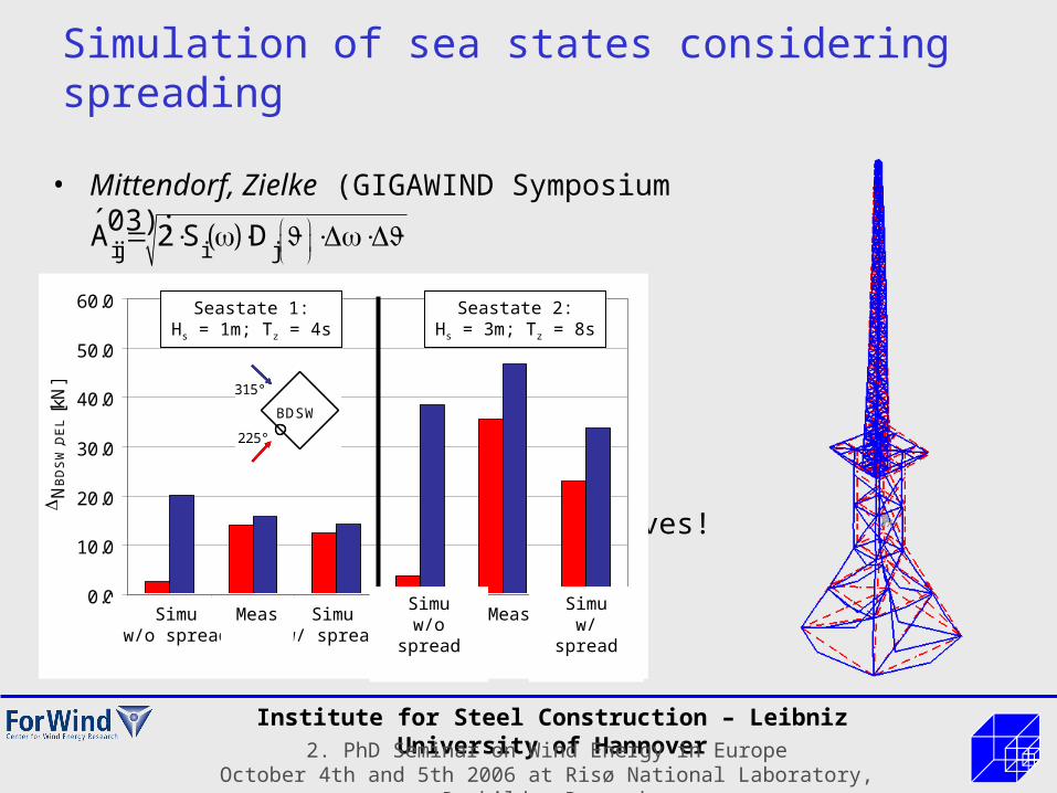
• Mittendorf, Zielke (GIGAWIND Symposium ´03):
expensive calculationnJonswap x nspreading partial waves!
ij i jA 2 S D
22D cos ;
2 2with, e.g.:
Simulation of sea states considering spreading
0.0
10.0
20.0
30.0
40.0
50.0
60.0
Simulationw/o spread
Messung Simulationw/ spread
Simulationw/o spread
Messung Simulationw/ spread
N
BD
SW
,DE
L [k
N]
Seastate 1:Hs = 1m; Tz = 4s
Seastate 2:Hs = 3m; Tz = 8s
0,0
10,0
20,0
30,0
40,0
50,0
60,0
Simulation Messung Simulation Messung
Seegangzustand 1:Hs=1m, Tz=4s
Seegangzustand 2:Hs=3m, Tz=6s
BDSWBDSW225°
BDSW
315°
BDSWBDSW225°
BDSW
315°
0,0
10,0
20,0
30,0
40,0
50,0
60,0
Simulation Messung Simulation Messung
Seegangzustand 1:Hs=1m, Tz=4s
Seegangzustand 2:Hs=3m, Tz=6s
BDSWBDSW225°
BDSW
315°
BDSWBDSW225°
BDSW
315°
Simuw/o spread
Simuw/ spread
Meas Simuw/o spread
Simuw/ spread
Meas

Institute for Steel Construction – Leibniz University of Hannover2. PhD Seminar on Wind Energy in Europe
October 4th and 5th 2006 at Risø National Laboratory, Roskilde, Denmark
Application to a Monopile
0
0,05
0,1
0,15
0,2
0,25
0,3N
NE
E
SE
S
SW
W
NW
4 possible cases:(with increasing calculation cost)
Long-term distribution
Short-term distribution
Case #1 Case #2 Case #3 Case #4

Institute for Steel Construction – Leibniz University of Hannover2. PhD Seminar on Wind Energy in Europe
October 4th and 5th 2006 at Risø National Laboratory, Roskilde, Denmark
Application to a Monopile (2)
0
0,05
0,1
0,15
0,2
0,25
0,3N
NE
E
SE
S
SW
W
NW
N
NE
E
SE
S
SW
W
NW
Relative Damage:
Dmax = 100 %
0
0,05
0,1
0,15
0,2
0,25
0,3N
NE
E
SE
S
SW
W
NW
N
NE
E
SE
S
SW
W
NW
Dmax = 37 %
0
0,05
0,1
0,15
0,2
0,25
0,3N
NE
E
SE
S
SW
W
NW
N
NE
E
SE
S
SW
W
NW
Dmax = 35 %
0
0,05
0,1
0,15
0,2
0,25
0,3N
NE
E
SE
S
SW
W
NW
N
NE
E
SE
S
SW
W
NW
Dmax = 46 %
Spreading should be considered, at least for monopiles Long-term distribution strongly site-dependant For jacket or tripod structures more investigations necessary

Institute for Steel Construction – Leibniz University of Hannover2. PhD Seminar on Wind Energy in Europe
October 4th and 5th 2006 at Risø National Laboratory, Roskilde, Denmark
Structural modeling
EF 1:0.616 Hz
EF 2:0.635 Hz
EF 3:1.452 Hz
EF 4:1.746 Hz
EF 5:1.825 Hz

Institute for Steel Construction – Leibniz University of Hannover2. PhD Seminar on Wind Energy in Europe
October 4th and 5th 2006 at Risø National Laboratory, Roskilde, Denmark
Local Joint Flexibilities
• In the FE model it is assumed that chords and braces are connected by rigid joints over-estimation of system stiffness!
• This has an influence on:– Structural dynamics– Fatigue (due to the distribution of
member forces)

Institute for Steel Construction – Leibniz University of Hannover2. PhD Seminar on Wind Energy in Europe
October 4th and 5th 2006 at Risø National Laboratory, Roskilde, Denmark
Local Joint Flexibilities
• Parameterized formulae acc. Buitrago et al. (e.g. in DNV OS-J101)
• Modeling of LJF using flex-elements:
Beam Elements
“Rigid link”
“Flex Element”Stiffness propertiesdetermined by para-meterized formulae
Institute for Steel Construction – Leibniz University of Hannover2. PhD Seminar on Wind Energy in Europe
October 4th and 5th 2006 at Risø National Laboratory, Roskilde, Denmark
1
10
100
1000
10000
100000
0 0.5 1 1.5 2
Frequency [Hz]
Glo
ba
l Mo
me
nt a
t mu
dlin
e [k
N²m
²]
)
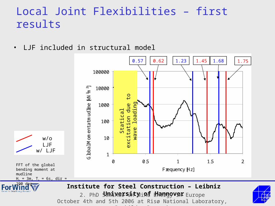
Local Joint Flexibilities – first results
• LJF included in structural model
FFT of the global bending moment at mudlineHs = 3m, Tz = 6s, dir = 290 deg
0.57 0.62 1.23 1.45 1.68 1.75
w/o LJF
w/ LJF Sta
tical
exc
itatio
n du
e to
w
ave
load
ing

Institute for Steel Construction – Leibniz University of Hannover2. PhD Seminar on Wind Energy in Europe
October 4th and 5th 2006 at Risø National Laboratory, Roskilde, Denmark
Local Joint Flexibilities - Outlook
Sub-structuring approach:• Use detailed models needed for
fatigue analysis
Beam Elements
Superelement: K, M, C18 DOF in the example
(6 per masternode)
• Advantage: use of existing detail models allows integrated workflow in the design
• More accurate than simplified approach
• Arbitrary joint geometries possible (e.g. Tripod)

Institute for Steel Construction – Leibniz University of Hannover2. PhD Seminar on Wind Energy in Europe
October 4th and 5th 2006 at Risø National Laboratory, Roskilde, Denmark
Thanks for your attention!