instruction and parts manual model m18team-twg.com/...operating-manuals/...manual.pdf · read this...
TRANSCRIPT

120612PMC 240
READ THIS MANUAL BEFORE INSTALLING, OPERATING ORSERVICING THIS PRODUCT. THIS MANUAL CONTAINS IMPORTANTINFORMATION. MAKE THIS MANUAL AVAILABLE TO ALL PERSONSRESPONSIBLE FOR THE OPERATION, INSTALLATION, SERVICINGAND MAINTENANCE OF THIS PRODUCT.
INSTRUCTION AND PARTS MANUAL
THE LOGICAL CHOICE
TWG CanadaLANTEC and Pullmaster Brands19350 – 22nd Ave • Surrey, BC V3S 3S6Voice: + 1 604-547-2100 • Fax: + 1 604-547-2147 • www.team-twg.com
MODEL M18PLANETARY HYDRAULIC WINCH

Effective 2011/10/01 SUPERSEDES ALL PRIOR WARRANTIES
LIMITED WARRANTY 50130-0
Seller warrants that each article (whether Gear Drive Products, Brake Products and/or Winch Products, all of which are covered hereunder) sold under this order shall at the time of shipment (i) conform to applicable specifications, and (ii) be free from defects in material and workmanship during normal and ordinary use and service (the "Warranty").
Buyer's exclusive remedy and Seller's sole obligation under this Warranty shall be, at Seller's option, to repair or replace any article or part thereof which has proven to be defective, or to refund the purchase price of such article or part thereof. Buyer acknowledges that Buyer is knowledgeable concerning the articles covered by this Warranty and sold in connection therewith which are being purchased, that Buyer has reviewed this Warranty and that the remedies provided hereunder are adequate and acceptable to Buyer.
This Warranty shall expire one (1) year from the date the article is first shipped by Seller. Notice of claimed breach of this Warranty must be given by Buyer to Seller within the applicable period. Such notice shall include an explanation of the claimed warranty defect and proof of date of purchase of the article or part thereof for which warranty coverage is sought. No allowances shall be made by Seller for any transportation, labor charges, parts, "in and out" costs, adjustments or repairs, or any other work, unless such items are authorized in writing and in advance by Seller. Nor shall Seller have any obligation to repair or replace items which by their nature are expendable.
If an article is claimed to be defective in material or workmanship, or not to conform to the applicable specifications, Seller will either examine the article at Buyer's site or issue shipping instructions for return to Seller. This Warranty shall not extend to any articles or parts thereof which have been installed, used, or serviced otherwise than in conformity with Seller's applicable specifications, manuals, bulletins, or instructions, or which shall have been subjected to improper installation, operation, or usage, misapplication, neglect, incorrect installation, overloading, or employment for other than normal and ordinary use and service. This Warranty shall not apply to any article which has been repaired, altered or disassembled, or assembled by personnel other than those of Seller. This Warranty shall not apply to any article upon which repairs or alterations have been made (unless authorized in writing and in advance by Seller). This Warranty shall not apply to any articles or parts thereof furnished by Seller to Buyer's specifications and/or furnished by Buyer or acquired from others at Buyer's request.
SELLER MAKES NO EXPRESS WARRANTIES AND NO IMPLIED WARRANTIES OF ANY KIND, OTHER THAN THE WARRANTY EXPRESSLY SET FORTH ABOVE. SUCH WARRANTY IS EXCLUSIVE AND IS MADE AND ACCEPTED IN LIEU OF ANY AND ALL OTHER WARRANTIES, EXPRESS OR IMPLIED, INCLUDING WITHOUT LIMITATION THE IMPLIED WARRANTIES OF MERCHANTABILITY AND FITNESS FOR A PARTICULAR PURPOSE.
Buyer expressly agrees that Seller is not responsible to perform any work or investigation related in any way to torsional vibration issues and is not responsible for the detection or remedy of Natural Frequency Vibration of the mechanical system in which the unit is installed. Buyer acknowledges, understands and agrees that this Warranty does not cover failures of the unit which result in any manner from the operation of the machine or unit at vibration frequencies at or near the natural frequency vibration of the machine in such a way that damage may result. Buyer expressly agrees that Seller is not responsible for failure damage or accelerated wear caused by machine or ambient vibration. Further, Buyer acknowledges and agrees that Buyer is always solely responsible for determination and final approval of the “application factor” which may be used in Seller’s calculations and this application factor is 1.0 unless otherwise stated in Seller’s quotation specifications.
The remedies for this Warranty shall be only those expressly set forth above, to the exclusion of any and all other remedies of whatsoever kind. The limited remedies set forth above shall be deemed exclusive, even though they may fail their essential purpose. No agreement varying or extending the foregoing Warranty, remedies, exclusions, or limitations shall be effective unless in writing signed by an executive officer of Seller and Buyer. This Warranty is non-transferable. If a party who had purchased articles from Buyer, or from persons in privity with Buyer, brings any action or proceeding against Seller for remedies other than those set forth in this Warranty, Buyer agrees to defend Seller against the claims asserted in such action or proceeding at Buyer’s expense, including the payment of attorneys’ fees and costs, and indemnify Seller and hold Seller harmless of, from and against all such claims, actions, proceedings or judgments therein. Buyer also agrees to defend and indemnify Seller of, from and against any loss, cost, damage, claim, debt or expenses, including attorneys’ fees, resulting from any claims by Buyer or third parties to property or injury to persons resulting from faulty installation, repair or modification of the article and misuse or negligent operation or use of the article, whether or not such damage to property or injury to persons may be caused by defective material, workmanship, or construction.
ADVISORY: Winches and hoists are not approved for lifting or handling personnel or persons unless specifically approved in writing from Seller for the specific intended application.
Under no circumstances shall Seller be liable (i) for any damage or loss to any property other than the warranted article or part thereof, or (ii) for any special, indirect, incidental, or consequential damage or loss, even though such expenses, damages, or losses may be foreseeable.
The foregoing limitations on Seller's liability in the event of breach of warranty shall also be the absolute limit of Seller's liability in the event of Seller's negligence in manufacture, installation, or otherwise, with regard to the articles covered by this Warranty, and at the expiration of the Warranty period as above stated, all such liabilities shall terminate. Buyer’s purchase of any article(s) covered by this Warranty shall constitute acceptance of the terms and conditions hereof and shall be binding upon Buyer and Buyer’s representatives, heirs and assigns. The laws of the Province of British Columbia shall govern Buyer’s rights and responsibilities in regard to this Warranty and the transaction(s) subject thereto, and the Province of British Columbia shall be the exclusive forum and jurisdiction for any action or proceedings brought by Buyer in connection herewith or any dispute hereunder. If any of the terms and conditions contained within this Warranty are void, the remaining provisions thereof are and shall remain valid and enforceable.

PAGE 1240 REV.051117
1. Do not install, operate or service winchbefore reading and understanding manufacturer'sinstructions.
2. The winch described herein is not designedfor operations involving lifting or moving personnel.
3. Do not lift or carry loads over people.
4. Do not exceed recommended operatingpressure (psi) and operating volume (gpm).
5. Do not jerk the winch. Always smoothlyaccelerate and decelerate load.
6. Do not operate a damaged, noisy ormalfunctioning winch.
7. Do not leave a load suspended for anyextended period of time.
8. Never leave a suspended load unattended.
9. Winch should be maintained and operatedby qualified personnel.
10. Inspect winch, rigging, mounting bolts andhoses before each shift.
11. Warm-up equipment before operating winch,particularly at low ambient temperatures.
12. Verify winch function by raising and loweringa full test load to a safe height before each shift.
13. Do not weld any part of the winch.
14. Verify gear lubrication and brake circulationsupply and return before operating winch.
15. Be sure of equipment stability beforeoperating winch.
16. Wear proper clothing to avoid entanglementin rotating machinery.
17. Always stand clear of the load.
The planetary hydraulic winches are made for hoisting and lowering loads and to be operated by trained and professionalpersonnel. They are not designed for operations involving lifting or moving personnel. The winches are powered by hydraulicpower. The ropes / cables for hoisting operations are not supplied by PULLMASTER. The winches are always assembledin an application, they do not function as an independent machine and it is not allowed to use them as such.
The winches are to be used within the specifications as listed in the manual under “SPECIFICATIONS”. Other use as foreseenin the functional description of the hydraulic winch is not allowed without written permission from PULLMASTER.
FAILURE TO COMPLY WITH THE FOLLOWING SAFETYRECOMMENDATIONS AND LOCAL RULES AND
REGULATIONS WILL RESULT IN PROPERTYDAMAGE, SEVERE INJURY OR DEATH.
Definition: Caution indicates a potentiallyhazardous situation which, if not avoided mayresult in minor or moderate injury.
Definition: Warning indicates a potentiallyhazardous situation which, if not avoided couldresult in death or serious injury.
Definition: Danger indicates a potentiallyhazardous situation which, if not avoided willresult in death or serious injury.
DANGER
SAFETY RECOMMENDATIONS
18. Use only recommended hydraulic oil and gearlubricant.
19. Keep hydraulic system clean and free fromcontamination at all times.
20. Maintain winch and equipment in good operatingcondition. Perform scheduled maintenance regularly.
21. Keep hands clear when winding wire rope ontothe winch drum.
22. Do not use the wire rope as a ground for welding.
23. Rig the winch carefully. Ensure that the wirerope is properly anchored to the correct cable anchorslot at the cable drum.
24. Do not lift a load with a twisted, kinked ordamaged wire rope.
25. Consult wire rope manufacturer for size, typeand maintenance of wire rope.elen
26. Maintain five wraps of wire rope on the cabledrum at all times.
27. In case of a power failure or breakdown leadingto an unexpected stop of the hydraulic power circuit,stand clear of the area and the load being hoisted, takethe necessary precautions to prevent access to areawhere the load is halted.
28. The noise level of the winch is 86 dBA measuredon a distance of 1.00 meter, 1.60 meters high. Themeasuring equipment used was: Realistic #42-3019.
29. Clean up any oil spillage immediately.
30. Wear proper clothing and personal protectionequipment such as, footwear, safety goggles and ahard hat. Read manual first.

PAGE 2 240 REV.980615
DESCRIPTION OF THE MODEL M18
GENERAL DESCRIPTION:The PULLMASTER Model M18 is a planetary, hydraulic winch having equal speed in both directions. The maincomponents of this unit are:
✛✛✛✛✛ hydraulic gear motor✛✛✛✛✛ multi-disc brake with static and dynamic function✛✛✛✛✛ primary planet reduction✛✛✛✛✛ final planet reduction✛✛✛✛✛ brake housing✛✛✛✛✛ final drive housing✛✛✛✛✛ cable drum
FUNCTION IN FORWARD ROTATION (HOISTING):In forward rotation, the output torque and rpm of the hydraulic motor are transmitted to the sungear of the primaryplanet reduction. The output torque and rpm of the primary reduction stage are transmitted to the final reductionstage by the final sungear shaft, which is splined to the primary planet hub. In forward rotation, or when a load israised, an over-running clutch, which connects the motor drive shaft to the automatic brake assembly, permits freerotation of the sungear without effecting the brake. When the winch rotation is stopped, the load on the cable drumcauses the over-running clutch to lock and the maximum load is held safely by the disc brake.
FUNCTION IN REVERSE ROTATION (LOWERING):In reverse rotation, hydraulic pressure from the reversing side of the hydraulic motor is channelled to the brakepiston, causing the brake piston to release the multi disc brake against a number of brake springs. The over-runningclutch, connecting the motor drive shaft to the brake assembly, locks, causing the brake discs to rotate betweendivider plates. Thus, a completely smooth lowering speed can be achieved in a stepless operation by modulationof the winch control valve handle. When the control handle is returned to neutral position, rotation stops and thedisc brake applies automatically.
During the lowering operation of the winch, the friction created by the brake discs results in temperature. Thistemperature is dissipated by an internal circulation flow, supplied out of the hydraulic motor, or from an externalsource, for models with external circulation (approximately 5 (US) gpm - 19 l/min). This circulation flow must bereturned directly to the reservoir with a permissible back pressure of 30 psi (2 bar).
IMPORTANT: Under no circumstances must the back pressure in the brake housing be permitted to exceed 30psi (2 bar). Excessive pressure in the brake housing will damage the oil seal separating the brakehousing from the drum interior. Damage to this seal will cause the drum to fill up with hydraulicfluid. In order to prevent potential damage to the drum seals and the end cover of the winch, whenthe cable drum fills up with hydraulic fluid, a breather relief (see PARTS REFERENCE, item 130)is installed on the end cover. The breather relief bleeds to atmosphere and serves as a warningsignal that the oil seal between the brake housing and drum has been damaged.

PAGE 3240 REV.980615
EXPLANATION OF MODEL CODING
X - XX - XX - XX X - X XXXX18BASIC UNIT SERIES M = Equal speed in both directions
SIZE OF UNIT
REDUCTION RATIOOnly used for non standard reduction ratios
TYPE OF BRAKE
-3 Automatic brake, clockwise drum rotation, internal circulation flow
-4 Automatic brake, external brake release, clockwise drum rotation,internal circulation flow
-5 Automatic brake, external brake release, counterclockwise drumrotation, internal circulation flow
-6 Automatic brake, counterclockwise drum rotation, internalcirculation flow
-7 Automatic brake, clockwise drum rotation, external circulation flow
-8 Automatic brake, external brake release, clockwise drum rotation,external circulation flow
-9 Automatic brake, external brake release, counterclockwise drumrotation, external circulation flow
-10 Automatic brake, counterclockwise drum rotation, externalcirculation flow
HYDRAULIC MOTOR -101 COMMERCIAL M365 hydraulic motor, 2.25 inch gear section
(Other gear sections for this motor are optional)
DRUM SIZE -1 8 1/2 inch drum diameter X 15 1/2 inch flange diameter X 10 inch length - STANDARD
(For other drum sizes refer to APPENDIX A)
OPTIONS
DESIGN REVISION
SPECIFICATION NUMBERDescribes features not identified by preceding codes
NOTE: Clockwise and counterclockwise drum rotation is the direction of rotation for pulling or hoisting,established by looking at the hydraulic motor.
M

PAGE 4 240 REV.980615
OPTIONS
CABLE DRUM SIZES:Aside from the standard drum sizes listed in APPENDIX A, the PULLMASTER Model M18 planetary winch canbe supplied with optional drums to accommodate large wire rope storage capacity.
DRUM GROOVING:Cable drums for the PULLMASTER Model M18 planetary winch can be grooved. Where this option is a requirement,it is necessary to state the size of wire rope which is to be used with the winch.
OPTIONAL GEAR SECTION FOR THE HYDRAULIC MOTOR:The performance of the standard PULLMASTER Model M18 planetary winch may be changed by using a differentdisplacement motor. (Contact the factory for performance information.)
HYDRAULIC MOTORS FOR HIGH PRESSURE HYDRAULIC SYSTEMS:The operating pressure of the PULLMASTER Model M18 planetary winch is limited to 2300 psi (159 bar). Forhydraulic systems operating with a higher range of hydraulic pressure, the winch can be supplied with a hydraulicpiston motor, which will provide for the same basic performance in terms of line pull and line speed capacity. (Contactthe factory for this requirement.)
FREESPOOLING:This option permits wire rope being pulled off the cable drum by an operator. Freespooling should not be confusedwith free fall. The freespool clutch cannot be disengaged or re-engaged with a load on the wire rope or while thecable drum is turning.
The PULLMASTER WINCH CORPORATION will consider other options for quantity requirements.
COUNTERCLOCKWISE ROTATION:The drum rotation of the standard PULLMASTER Model M18 planetary winch is clockwise for hoisting when lookingat the hydraulic motor of the winch. Drum rotation for counterclockwise hoisting direction is available as an option.
EXTERNAL BRAKE RELEASE:PULLMASTER planetary winches can be supplied with an external brake release which permits release of theautomatic disc brake from an external pressure source.
FAILURE TO PROPERLY VENT EXTERNAL BRAKE RELEASEPORT WILL TRAP BRAKE PRESSURE AND ALLOW THE
LOAD TO DROP, CAUSING PROPERTY DAMAGE, SEVEREINJURY OR DEATH. WINCHES SUPPLIED WITH EXTERNAL
RELEASE OPTION MUST BE CONNECTED ACCORDINGTO TYPICAL HYDRAULIC CIRCUIT.
DANGER

PAGE 5240 REV.001122
SPECIFICATIONSPerformance specifications are based on standard hydraulic motor, gear ratio and cable drum with 3/4 inch diameterwire rope. For other cable drums refer to APPENDIX A. For other reductions or motors, refer to supplement insideback cover. Performance specifications for winches supplied with optional motors are provided in attachedsupplement.
CABLE DRUM DIMENSIONS (STANDARD DRUM):Barrel diameter 8.50 in 216 mmFlange diameter 15.50 in 394 mmBarrel length 10.00 in 254 mm
CABLE STORAGE CAPACITY:(Size of wire rope) 3/8 in 615 ft 187 m
7/16 in 494 ft 151 m1/2 in 332 ft 101 m
9/16 in 310 ft 94 m5/8 in 239 ft 73 m3/4 in 170 ft 52 m7/8 in 113 ft 34 m
MAXIMUM OPERATING PRESSURE: 2300 psi 159 bar
MAXIMUM OPERATING VOLUME: 76 (US) gpm 288 l/min
MINIMUM OPERATING VOLUME: 20 (US) gpm 76 l/min
DRUM TORQUE AT MAXIMUM PRESSURE: 83,250 lb-in 9,406 Nm
DRUM RPM AT MAXIMUM PRESSURE: 50.5 rpm
LINE PULL AT MAXIMUM PRESSURE: Bare drum 18,000 lb 80.1 kN
Full drum 11,288 lb 50.2 kN
LINE SPEED AT MAXIMUM VOLUME: Bare drum 122 fpm 37 m/min Full drum 195 fpm 59 m/min
PERMISSIBLE SYSTEM BACK PRESSURE ATMOTOR RETURN PORT: 65 psi 4.5 bar
PERMISSIBLE PRESSURE AT CIRCULATIONSUPPLY PORT: 30 psi 2 bar
LUBRICATING OIL: Refer to RECOMMENDATIONS for viscosity and instructions.Refer to APPENDIX A for oil volume required.

PAGE 6
180
55
160
49
140
43
120
37
100
30
80
24
60
18
40
12
20
6
70 265
60 227
50 189
40 152
30 114
20 76
10 38
58
LINE PULL - kN
LINE SPEED - m/min
FULL DRUM BARE DRUM
2000
2500
1500
1000
500
0
80
0
1800015000120009000600030000
0 13.3 26.7 40.0 53.4 66.7 80.1172
138
103
69
34
0
LINE PULL - lb
OIL
PR
ES
SU
RE
- p
si
OIL
PR
ES
SU
RE
- b
ar
0 191
0
0
LINE SPEED - fpm
303
OIL
VO
LUM
E -
(U
S)g
pm
OIL
VO
LUM
E -
l/m
in
BARE DRUM
FULL DRUM
PERFORMANCE GRAPHSPG-M18-B
LINE PULL VS. OIL PRESSURE
LINE SPEED VS. OIL VOLUME
Performance graphs are based on standard hydraulic motor, gear ratio and cable drum with3/4 inch diameter wire rope.
240 REV.980615
PAGE 7
HC-M18-E
240 REV.030505
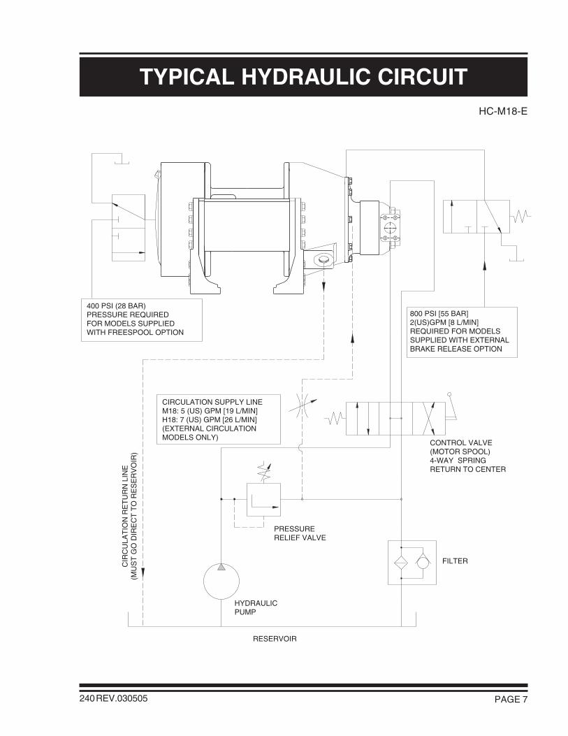
TYPICAL HYDRAULIC CIRCUIT
800 PSI [55 BAR]2(US)GPM [8 L/MIN]REQUIRED FOR MODELSSUPPLIED WITH EXTERNALBRAKE RELEASE OPTION
CIR
CU
LAT
ION
RE
TU
RN
LIN
E(M
US
T G
O D
IRE
CT
TO
RE
SE
RV
OIR
)
FILTER
HYDRAULICPUMP
RESERVOIR
CONTROL VALVE(MOTOR SPOOL)4-WAY SPRINGRETURN TO CENTER
PRESSURERELIEF VALVE
CIRCULATION SUPPLY LINEM18: 5 (US) GPM [19 L/MIN]H18: 7 (US) GPM [26 L/MIN](EXTERNAL CIRCULATIONMODELS ONLY)
400 PSI (28 BAR)PRESSURE REQUIREDFOR MODELS SUPPLIEDWITH FREESPOOL OPTION

PAGE 8
RECOMMENDATIONS
240 REV.030505
HYDRAULIC FLUID:The hydraulic fluid selected for use with PULLMASTERplanetary winches should be a high grade, petroleumbased fluid, with rust, oxidation and wear resistance.Fluid cleanliness and operating viscosity are critical towinch reliability, efficiency and service life.
For optimum performance, the recommended viscosityrange at operating temperature is 81 - 167 SUS (16 - 36CS). For extreme operating conditions of short duration,the maximum viscosity range of 58 - 4635 SUS (10 -1000 CS) should not be exceeded.
For optimum performance, the winch recommendedhydraulic fluid temperature operating range is 80 - 150F(27 - 66 C). For extreme operating conditions of shortduration, the maximum temperature range of -5 - 180F(-21 - 82 C) should not be exceeded.
LUBRICATION:The winch gear train requires oil bath lubrication. Thewinch is shipped from the factory without lubricating oil.
IMPORTANT: ADD LUBRICATING OIL BEFORE RUNNING WINCH.
Refer to INSTALLATION DIMENSIONS for location oflubricating oil fill port. Refer to APPENDIX A for quantityof oil required. For normal operating temperature useSAE 90 lubricating oil. For temperatures beyond normaloperating range, consult lubricating oil supplier or factory.
HYDRAULIC PUMP:For maximum performance of the PULLMASTERplanetary winch, the hydraulic pump must supply themaximum flow of hydraulic fluid at the hydraulic pressurestated in SPECIFICATIONS.
HYDRAULIC CONTROL VALVE:The standard control valve used for operation of thePULLMASTER planetary winch must have a four-way,spring return to neutral feature, which provides for openflow from the pressure ports of the winch to the reservoirin neutral position of the control (motor spool). It isimportant to point out that good speed control, especiallywhen lowering a load, depends on the "metering"characteristics of the control valve. The better the oilflow is "metered" the better will be the speed control.
HYDRAULIC PRESSURE RELIEF:The hydraulic circuit for the PULLMASTER planetarywinch requires a pressure relief set at the operatingpressure (see SPECIFICATIONS). Usually, a pressurerelief is part of the hydraulic control valve. Where this isnot the case, a separate pressure relief valve must beinstalled and set at the recommended maximum pressure.
HYDRAULIC RESERVOIR:It is recommended that the hydraulic reservoir hassufficient capacity to provide good heat dissipation inorder to prevent over-heating of the hydraulic fluid. Thehydraulic reservoir should be made from clean andscale-free material to prevent contamination of thehydraulic fluid. In order to prevent air from being mixedwith the hydraulic fluid, the reservoir should have anover-flow baffle separating the return lines from thesuction line and all return lines should enter the reservoirbelow the fluid level. The reservoir should be mountedclose to and above the hydraulic pump in a locationwhich provides for free air circulation around the reservoir.
HYDRAULIC HOSES:The following hydraulic hoses are recommended formaximum efficiency of the PULLMASTER Model M18planetary winch:
Pressure lines: Equivalent to SAE 100R10-24Circulation return line: Equivalent to SAE 100R4-12Circulation supply line*: Equivalent to SAE 100R6-6
*Only for models with external circulation
It is recommended that a larger size of hydraulic hose isinstalled where the pressure lines or the circulation linesare excessively long.
HYDRAULIC FILTER:Hydraulic filter recommendations for the hydraulic circuitof the PULLMASTER planetary winch, based on a returnline filter, are given as follows:
Average Atmosphere: 10 micronsDusty Atmosphere: 5 microns
In order to prevent accidental stoppage of the return lineflow, the oil filter should have a by-pass feature.
USE OF AN E STOP:(FOR EUROPEAN MACHINERY DIRECTIVE APPLICATIONS)
The use of an E stop (emergency) is mandatory in thecontrols circuit. The E stop is to be placed in theoperator's control panel. The E stop must be designedand placed in line with EN 60204 and EN 418.

PAGE 9
INSTALLATION INSTRUCTIONS
240 REV.980615
The initial installation or mounting of a PULLMASTER planetary winch is critically important for proper operationand performance. If the winch is mounted to an uneven surface, the centre line of the unit can be distorted to a pointwhere the winch will not operate in either direction. It is therefore very important that the following instructions areobserved when a PULLMASTER planetary winch is installed:
1) Make certain that the mounting platform is sufficiently strong in order to avoid deflection when a load is lifted.
2) Set the winch on the mounting platform and check for surface contact on all mounting pads of the winch.
3) If there is a space between the mounting surface and one of the mounting pads, the mounting surface is noteven and the space below the mounting pad must be shimmed. If this condition exists, proceed as follows:
a) Install mounting bolts snug tight on the three mounting pads which are in contact with the mounting surface.(For mounting bolt size and grade see INSTALLATION DIMENSIONS.)
b) Measure the space underneath the fourth mounting pad with a feeler gauge and use shim stock of equivalentthickness in the space between the mounting pad and the mounting surface.
c) Only after this procedure should the fourth mounting bolt be installed. Tighten all four bolts per BOLTTORQUE CHART.
4) Fill the winch with lubricating oil. (See APPENDIX A for oil volume required.)
5) Use recommended circuit components and hydraulic hoses.
6) The circulation return line of the winch should be plumbed in such a manner that the brake housing remainsfull of oil at all times. Connect the return line directly to reservoir. Do not connect to a common return line.
7) Before operating the winch with a load, verify adequate circulation flow through the circulation return line asstated in TYPICAL HYDRAULIC CIRCUIT. Verify that pressure measured at the circulation supply port doesnot exceed the permissible pressure stated in SPECIFICATIONS. Winches equipped with the internalcirculation option will supply circulation flow only when the winch is run in the lowering direction.
8) Verify that breather relief, item 130, is above oil level on end cover, item 120. Rotate end cover if breather reliefis below oil level.
IMPORTANT:
FAILURE TO FOLLOW INSTALLATION INSTRUCTIONS WILLRESULT IN PROPERTY DAMAGE, SEVERE INJURY OR DEATH.
Do not replace breather relief with a pipe plug. The breather relief does not prevent oilseal failure but serves as an indicator or warning that the oil seals between brakehousing and the cable drum interior have failed and must be replaced immediately. Ifthese oil seals are changed, additional failure of the drum seal and potential damageto the end cover is prevented.
DANGER

PAGE 10
OPERATING INSTRUCTIONS
240REV.051117
SI1013 - 18
FAILURE TO FOLLOW OPERATING INSTRUCTIONS WILLRESULT IN PROPERTY DAMAGE, SEVERE INJURY OR DEATH.
WIRE ROPE INSTALLATIONClockwise hoisting winch shown.(Use cable anchor slot on oppositeside of drum for counterclockwisehoisting winch.)
Feed the wire rope through the cableanchor slot. Loop rope back into slotas shown. Insert cable anchor intoslot and pull rope tight to wedge ropein slot.
2) On wire rope installation, care must be taken that the wire rope is wrapped completely around the cable anchorand properly pulled into the cable anchor slot in the cable drum. The cable drum requires 5 wraps of wire ropefor safety.
3) The winch operation is controlled by a single control valve lever which has a forward, a reverse and a neutralposition. Speed control in either direction is obtained by modulation of the control valve lever. Maximum linespeed in either direction is obtained when the control valve lever is moved as far as it can go. The disc brakeof the winch will come on automatically when the winch control lever is returned to neutral.
4) Always warm up equipment prior to operating winch, particularly in low ambient temperature. Circulate hydraulicoil through the winch control valve for several minutes to warm the hydraulic system. To prime the winch withwarm oil, operate the winch at slow speed, forward and reverse, several times.
5) Prevent corrosion damage to winch interior. If not used regularly, run winch up and down at least once everytwo weeks.
6) To ensure proper winch installation and function, raise and lower a full test load to a safe height before usingwinch for regular operation at the start of each shift.
If, after a new installation, the winch does not function properly, refer to the TROUBLESHOOTING section ofthis manual.
IMPORTANT: The wire rope is not part of the winch and is not covered by this manual. Refer to the wire ropemanufacturer's handling, inspection and maintenance recommendations to avoid potentialaccidents.
After the PULLMASTER planetary winch has been installed in accordance with the INSTALLATION INSTRUCTIONS,the wire rope can be fastened to the cable drum.
1) The cable drum of the PULLMASTER planetary winch has two cable anchor slots, one for clockwise and onefor counterclockwise hoisting. Standard rotation for hoisting is clockwise when looking at the hydraulic motorof the unit. It is critical to select the cable anchor slot which will permit winding of the wire rope on the drumin the correct direction of rotation. If the wire rope is wound on the cable drum in the wrong direction of rotation,the winch will have no braking capacity. Each winch is shipped from the factory with a label on the drumindicating the correct cable anchor slot.
DANGER
CABLE ANCHOR SLOT
CABLE ANCHOR
PAGE 11
TROUBLE SHOOTING
240 REV.951201
FAILURE PROBABLE CAUSE
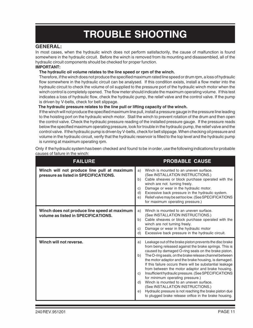
Winch will not produce line pull at maximumpressure as listed in SPECIFICATIONS.
Winch does not produce line speed at maximumvolume as listed in SPECIFICATIONS.
Winch will not reverse.
a) Winch is mounted to an uneven surface.(See INSTALLATION INSTRUCTIONS.)
b) Cable sheaves or block purchase operated with thewinch are not turning freely.
c) Damage or wear in the hydraulic motor.d) Excessive back pressure in the hydraulic system.e) Relief valve may be set too low. (See SPECIFICATIONS
for maximum operating pressure.)
a) Winch is mounted to an uneven surface.(See INSTALLATION INSTRUCTIONS.)
b) Cable sheaves or block purchase operated with thewinch are not turning freely.
c) Damage or wear in the hydraulic motord) Excessive back pressure in the hydraulic circuit.
a) Leakage out of the brake piston prevents the disc brakefrom being released against the brake springs. This iscaused by damaged O-ring seals on the brake piston.
b) The O-ring seals, on the brake release channel betweenthe motor adaptor and the brake housing, is damaged.If this failure occurs there will be substantial leakagefrom between the motor adaptor and brake housing.
c) Insufficient hydraulic pressure. (See SPECIFICATIONSfor minimum operating pressure.)
d) Winch is mounted to an uneven surface.(See INSTALLATION INSTRUCTIONS.)
e) Hydraulic pressure is not reaching the brake piston dueto plugged brake release orifice in the brake housing.
GENERAL:In most cases, when the hydraulic winch does not perform satisfactorily, the cause of malfunction is foundsomewhere in the hydraulic circuit. Before the winch is removed from its mounting and disassembled, all of thehydraulic circuit components should be checked for proper function.IMPORTANT:
The hydraulic oil volume relates to the line speed or rpm of the winch.Therefore, if the winch does not produce the specified maximum rated line speed or drum rpm, a loss of hydraulicflow somewhere in the hydraulic circuit can be analysed. If this condition exists, install a flow meter into thehydraulic circuit to check the volume of oil supplied to the pressure port of the hydraulic winch motor when thewinch control is completely opened. The flow meter should indicate the maximum operating volume. If this testindicates a loss of hydraulic flow, check the hydraulic pump, the relief valve and the control valve. If the pumpis driven by V-belts, check for belt slippage.
The hydraulic pressure relates to the line pull or lifting capacity of the winch.If the winch will not produce the specified maximum line pull, install a pressure gauge in the pressure line leadingto the hoisting port on the hydraulic winch motor. Stall the winch to prevent rotation of the drum and then openthe control valve. Check the hydraulic pressure reading of the installed pressure gauge. If the pressure readsbelow the specified maximum operating pressure, look for trouble in the hydraulic pump, the relief valve and thecontrol valve. If the hydraulic pump is driven by V-belts, check for belt slippage. When checking oil pressure andvolume in the hydraulic circuit, verify that the hydraulic reservoir is filled to the top level and the hydraulic pumpis running at maximum operating rpm.
Only if the hydraulic system has been checked and found to be in order, use the following indications for probablecauses of failure in the winch:

PAGE 12 240 REV.951201
TROUBLE SHOOTING CONTINUED
FAILURE PROBABLE CAUSE
a) Brake plates or divider plates have been damaged bycontamination in the hydraulic fluid, or lack of circulationflow in the brake housing.
b) Brake piston is seized in the brake housing becauseof contamination in the hydraulic fluid.
c) Excessive back pressure in the return line causes thebrake to be released.
d) Control valve has incorrect spool, which trapshydraulic pressure in the brake piston when the controlvalve handle is returned to neutral position. For properfunction of the automatic brake, both pressure ports ofthe winch must be open to the reservoir in neutralposition of the control valve.
e) Wire rope is fastened to the incorrect cable anchor slot.f) Sprag clutch is damaged or surfaces where sprag
clutch engages on motor drive shaft or brake hub areworn or indented.
g) Winch supplied with external brake release option isnot plumbed per HYDRAULIC CIRCUIT. Failure tovent external brake release port to reservoir may trappressure and cause winch brake to slip.
a) Pump is too slow. Pump rpm must be maintained atnormal operating speed when a load is lowered.
b) Brake is running too hot. This is caused by a completelack of, or insufficient, circulation flow. To check thecirculation, observe the flow of oil from the circulationreturn line of the winch (see TYPICAL HYDRAULICCIRCUIT) when the winch is reversed.
c) Control valve has poor metering characteristics.d) Damaged brake plates or divider plates.e) The over-running clutch, which connects the motor
shaft with the brake assembly, is damaged.f) Air mixed with hydraulic oil (foamy oil).
a) Oil leaks from the hydraulic motor flange and the motoradaptor are caused by damaged O-ring seals.
b) Oil leaks occurring between the cable drum flangesand housings are caused by excessive pressure in thebrake housing. Excessive pressure will damage the oilseal which separates the brake housing from the cabledrum interior.
c) If the breather relief on the end cover leaks, the sealbetween the drum interior and the brake housing isdamaged and must be replaced. This condition iscaused by excessive pressure in the brake housing ofthe winch, operation with the incorrect hydraulic fluidduring cold weather, or a restriction in the circulationreturn line leading back to tank.
Brake will not hold.
Brake vibrates when lowering a load.
Oil leaks.
Refer to the SERVICE INSTRUCTIONS if it becomes necessary to disassemble the Model M18 winch.

PAGE 13240 REV.980615
SERVICE INSTRUCTIONSGENERAL:Before attempting disassembly of the PULLMASTER Model M18 planetary winch, the following instructions fordisassembly and reassembly should be read and understood:
It is suggested that all expendable parts, such as O-rings and oil seals, are not reused on reassembly. It is thereforeimportant to have a seal kit (Part No. 23135) and, providing the hydraulic motor has to be serviced, a seal kit (PartNo. 23139) on hand before the unit is taken apart.
NOTE: Backup washers may be included with seal kit. Install with oil seals as per instructions. If not present in seal kit, the oil seals supplied do not require backup washers.
A clean working area is of prime importance, similar to conditions used for service work on any other hydraulic component.
All parts, as they are removed from the winch assembly, should be inspected for wear and damage. Worn ordamaged parts must be replaced. Thoroughly clean parts before reassembly. Do not use solvent to clean the brakefriction plates.
During reassembly, lubricate all O-rings and oil seals with grease before installation.
In the following service instructions, reference to parts is made by numbers and shown on the applicable group drawings.
DISASSEMBLYFor the majority of required service or repair work, disassembly is required only on the brake housing of thePULLMASTER Model M18 planetary winch. There are no special tools needed for the service or repair workand no adjustments or calibrations are necessary. Proceed with the disassembly as follows:
DISASSEMBLY OF HYDRAULIC MOTOR ASSEMBLY:If the analysed service or repair work requires access to the interior of the brake housing, the hydraulic motor shouldnot be disassembled. In this case, the hydraulic motor should be removed together with the motor adaptor as acomplete assembly. If a problem has been analysed to be in the hydraulic motor, proceed with the disassemblyas follows:
1) Remove the four hex capscrews, item 951, together with the lockwashers, item 953, from the motor assembly.
IMPORTANT: Failure to exercise care when removing the motor port end cover or gear housing couldpermanently damage the machined surfaces of these motor components. Take care notto damage machined surfaces of motor components at disassembly.
2) Remove (pry loose if necessary) port end cover, item 870, together with two bushings, item 875. Two dowelpins, item 865, which are hollow for the capscrews to go through, will stay in either the port end cover or in thegear housing, item 861.
3) Remove gear set, item 881, which consists of two gears which are a matched set.
4) As the gears are removed, so is a thrust plate, item 885, two end seals, item 887, two side seals, item 891,and a backup seal, item 897. Discard end, side and backup seals.
5) Remove gear housing, item 861, together with gasket seals, item 869, and the remaining thrust plate with itsend, side and backup seals. Discard the gasket, end, side and backup seals.
End, side, backup and gasket seals in the hydraulic motor assembly are not part of the winch seal kit. The sealkit for the hydraulic motor can be ordered from the factory under Part No. 23139. All parts of the hydraulic motor,with the exception of the motor adaptor, item 800, and the port end cover, item 870, are standard parts of theCOMMERCIAL M365 hydraulic motor, having a 2.25 inch gear section. All of these parts can be ordered fromCOMMERCIAL INTERTECH dealers in Canada, the United States and in most overseas areas. If there is noCOMMERCIAL INTERTECH representation, all parts for the hydraulic motor can be ordered from the factory.

PAGE 14 240 REV.980615
SERVICE INSTRUCTIONS CONTINUED
REMOVAL OF HYDRAULIC MOTOR ASSEMBLY:If disassembly of the hydraulic motor is not necessary, proceed as follows:
1) Remove the eight hex head capscrews, item 821, with lockwashers, item 823, from the motor adaptor, item800. Since the brake springs, item 752, apply pressure against the inside of the motor adaptor, it isrecommended that the hex capscrews are unscrewed, one turn at a time, until the spring pressure has beenreleased. The complete motor assembly, including the motor adaptor, can now be removed from the brakehousing assembly.
2) Remove and discard three O-rings, item 801, and O-ring, item 707. (O-rings, item 801, seal the pressure transferhole for the automatic brake release and are situated on the flange of the brake housing.)
DISASSEMBLY OF BRAKE HOUSING ASSEMBLY:1) After the motor assembly has been removed, all parts of the brake assembly are accessible. Remove 10 brake
springs, item 752. Thoroughly examine springs for damage and measure overall length. Overall spring lengthshould be 2.27 inch. If any spring measures less than 2.21 inch, replace all springs as a set.
2) Pull the motor drive shaft, item 730, and complete brake hub assembly from the brake housing.
3) Disassemble brake hub assembly by removing circlip, item 719, from motor drive shaft. Remove motor driveshaft from brake hub, item 720. Remove sprag clutch aligners, items 722 and 724, and sprag clutch, item 723,from brake hub.
MINOR SURFACE DEFECTS WHERE THE SPRAG CLUTCH ENGAGES THEMOTOR DRIVE SHAFT AND BRAKE HUB, WILL RESULT IN BRAKEFAILURE AND ALLOW THE LOAD TO DROP, CAUSING PROPERTYDAMAGE, SEVERE INJURY OR DEATH. THOROUGHLY INSPECT
THESE AREAS AND, IF NECESSARY, REPLACE MOTORDRIVESHAFT, SPRAG CLUTCH AND BRAKE HUB AS A SET.
4) Thoroughly inspect motor drive shaft, item 730, and brake hub, item 720, particularly the surfaces where thesprag clutch, item 723, engages. If any indentation or surface damage is detected, replace brake hub, spragclutch and motor drive shaft as a set.
5) Pull the brake piston, item 750, out of the brake housing using two 5/8-11NC bolts screwed into the two pullerholes in the piston and discard O-rings, item 751 and item 753.
6) Thoroughly examine the inner bores of the brake housing and the outer diameters of the brake piston for scoringcaused by hydraulic fluid contamination. Minor surface damage may be repaired by polishing with a fine emerycloth.
DAMAGED FRICTION OR DIVIDER PLATES WILL REDUCE BRAKINGCAPACITY AND ALLOW THE LOAD TO DROP, CAUSING PROPERTY
DAMAGE, SEVERE INJURY OR DEATH. SOLVENT MAY DAMAGE THEFRICTION PLATES. DO NOT USE SOLVENT TO CLEAN THE FRICTIONPLATES. PERFORM THOROUGH INSPECTION AND, IF NECESSARY,
REPLACE FRICTION AND DIVIDER PLATES AS A SET.
7) Remove six friction plates, item 715, and seven divider plates, item 713, and inspect for damage or wear. Platesshould be flat and smooth. Plates should not show heat discoloration. Paper material on friction plates shouldbe intact and grooved. If any damage is detected, replace friction and divider plates as a set.
DANGER
DANGER
PAGE 15240 REV.951201
SERVICE INSTRUCTIONS CONTINUED
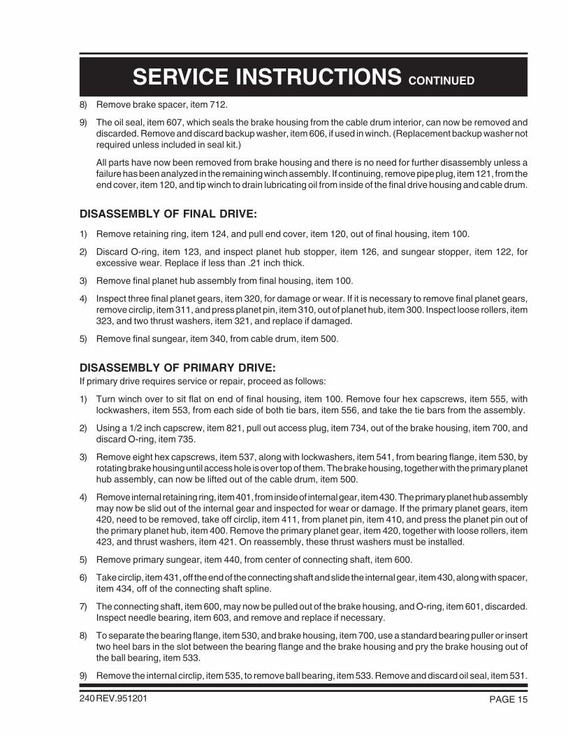
8) Remove brake spacer, item 712.
9) The oil seal, item 607, which seals the brake housing from the cable drum interior, can now be removed anddiscarded. Remove and discard backup washer, item 606, if used in winch. (Replacement backup washer notrequired unless included in seal kit.)
All parts have now been removed from brake housing and there is no need for further disassembly unless afailure has been analyzed in the remaining winch assembly. If continuing, remove pipe plug, item 121, from theend cover, item 120, and tip winch to drain lubricating oil from inside of the final drive housing and cable drum.
DISASSEMBLY OF FINAL DRIVE:
1) Remove retaining ring, item 124, and pull end cover, item 120, out of final housing, item 100.
2) Discard O-ring, item 123, and inspect planet hub stopper, item 126, and sungear stopper, item 122, forexcessive wear. Replace if less than .21 inch thick.
3) Remove final planet hub assembly from final housing, item 100.
4) Inspect three final planet gears, item 320, for damage or wear. If it is necessary to remove final planet gears,remove circlip, item 311, and press planet pin, item 310, out of planet hub, item 300. Inspect loose rollers, item323, and two thrust washers, item 321, and replace if damaged.
5) Remove final sungear, item 340, from cable drum, item 500.
DISASSEMBLY OF PRIMARY DRIVE:If primary drive requires service or repair, proceed as follows:
1) Turn winch over to sit flat on end of final housing, item 100. Remove four hex capscrews, item 555, withlockwashers, item 553, from each side of both tie bars, item 556, and take the tie bars from the assembly.
2) Using a 1/2 inch capscrew, item 821, pull out access plug, item 734, out of the brake housing, item 700, anddiscard O-ring, item 735.
3) Remove eight hex capscrews, item 537, along with lockwashers, item 541, from bearing flange, item 530, byrotating brake housing until access hole is over top of them. The brake housing, together with the primary planethub assembly, can now be lifted out of the cable drum, item 500.
4) Remove internal retaining ring, item 401, from inside of internal gear, item 430. The primary planet hub assemblymay now be slid out of the internal gear and inspected for wear or damage. If the primary planet gears, item420, need to be removed, take off circlip, item 411, from planet pin, item 410, and press the planet pin out ofthe primary planet hub, item 400. Remove the primary planet gear, item 420, together with loose rollers, item423, and thrust washers, item 421. On reassembly, these thrust washers must be installed.
5) Remove primary sungear, item 440, from center of connecting shaft, item 600.
6) Take circlip, item 431, off the end of the connecting shaft and slide the internal gear, item 430, along with spacer,item 434, off of the connecting shaft spline.
7) The connecting shaft, item 600, may now be pulled out of the brake housing, and O-ring, item 601, discarded.Inspect needle bearing, item 603, and remove and replace if necessary.
8) To separate the bearing flange, item 530, and brake housing, item 700, use a standard bearing puller or inserttwo heel bars in the slot between the bearing flange and the brake housing and pry the brake housing out ofthe ball bearing, item 533.
9) Remove the internal circlip, item 535, to remove ball bearing, item 533. Remove and discard oil seal, item 531.

PAGE 16
SERVICE INSTRUCTIONS CONTINUED
240 REV.951201
10) To separate the final drive housing, item 100, and cable drum, item 500, first remove the external circlip, item513, off the end of the cable drum then insert two heel bars in the slot between the final drive housing and thecable drum and pry the cable drum out of the ball bearing, item 103.
11) Remove the internal circlip, item 109, to remove ball bearing, item 103. Remove and discard oil seal, item 105.
The PULLMASTER Model M18 has now been completely disassembled.
REASSEMBLYfffffffff
Thoroughly clean all parts. Use only new, well-greased O-rings and oil seals. Unless otherwise specified, torquefasteners per BOLT TORQUE CHART at back of manual.
REASSEMBLY OF FINAL DRIVE:Reassemble final drive end of winch as follows:
1) Press new, well-greased oil seal, item 105, into final housing, item 100.
2) Press ball bearing, item 103, into final housing and secure with circlip, item 109.
3) Press cable drum, item 500, into ball bearing, item 103, and secure with circlip, item 513.f
4) Reassemble final planet hub assembly. Use grease to temporarily hold 22 loose rollers, item 323, in the boreof the planet gear, item 320. Position thrust washers, item 321, on either side of planet gear and press planetpin, item 310, into the final planet hub, item 300. Retain with circlip, item 311.
f
5) Insert final planet hub assembly into final housing, item 100. Ensure that planet hub spline is fully engaged withcable drum, item 500.
6) Install new, well-greased O-ring, item 123, into end cover, item 120. Verify that planet hub stopper, item 126,and sungear stopper, item 122, are installed into end cover.
ff
7) Gently insert end cover into final housing, item 100, and fasten with retaining ring, item 124.
8) Temporarily remove breather relief valve, item 130, from end cover. Turn winch up on end with cable drumopening upwards.
REASSEMBLY OF PRIMARY DRIVE:Reassemble primary drive as follows:
1) Reassemble primary planet hub assembly. Use grease to temporarily hold 20 loose rollers, item 423, in the boreof planet gear, item 420. Verify placement of sungear stopper, item 444. Position thrust washers, item 421, oneither side of planet gear and press planet pin, item 410, into final planet hub, item 400. Retain with circlip, item411.
2) Press new, well-greased oil seal, item 531, into bearing flange, item 530. Press ball bearing, item 533, intobearing flange and secure with retaining ring, item 534.
3) Press bearing flange assembly onto brake housing, item 700, and install new, well-greased O-ring, item 539.
4) Press new, well-greased oil seal, item 607, into bore in connecting shaft, item 600. If a backup washer, item606, is included in seal kit, install it behind oil seal.
5) Install new, well-greased O-ring, item 601, onto connecting shaft and insert through bore of brake housing, item700. Place spacer, item 434, onto shoulder of internal gear, item 430, and slide internal gear onto spline ofconnecting shaft. Fasten with circlip, item 431.

PAGE 17
SERVICE INSTRUCTIONS CONTINUED
240 REV.980615
6) Insert primary sungear, item 440, between three primary planet gears, item 420, and insert sungear shaft intoconnecting shaft, engaging planet gears with internal gear. Fasten with retaining ring, item 401.
7) Insert final sungear, item 340, into cable drum and engage three planet gears, item 320.
8) Lower brake housing assembly onto cable drum while engaging spline of final sungear with primary planet hub,item 400. Line up mounting holes of bearing flange, item 530, with those in the cable drum.
9) Rotate brake housing to line up access hole to fasten bearing flange to cable drum using six capscrews, item537, and lockwashers, item 541.
10) Install new, well-greased O-ring, item 735, into access plug, item 734. Install access plug into access holeinside brake housing.
11) Fasten two tie bars, item 556, using 16 capscrews, item 555, and lockwashers, item 553.
REASSEMBLY OF BRAKE HOUSING ASSEMBLY:Reassemble brake housing assembly as follows:
1) Install sprag clutch, item 723, into bore of brake hub, item 720. Position sprag clutch aligners, item 722 anditem 724, on either side of brake hub. Carefully slide motor drive shaft, item 730, into brake hub assembly andsecure with circlip, item 727. Verify that circlips, item 719 and item 731, are installed on motor drive shaft.
2) Carefully slide motor drive shaft, item 730, with brake hub assembly, into connecting shaft until it engages splineof primary sungear, item 440.
IMPORTANT: For proper brake function, verify that sprag clutch is installed correctly. When viewed fromthe motor end, the motor drive shaft of a clockwise hoisting winch must turn freely clockwiseand lock in the counterclockwise direction.
3) Install brake spacer, item 712, into brake housing.
4) Starting and finishing with a divider plate, alternately install seven divider plates, item 713, and six frictionplates, item 715.
5) Liberally grease O-ring, item 751, and O-ring, item 753, and install on brake piston, item 750.
6) Slide brake piston into the brake housing with holes for brake springs facing out of brake housing assembly.
7) Install 14 brake springs, item 752, in brake piston using hole pattern shown:
INCORRECT ASSEMBLY OF THE FRICTION PLATE AND DIVIDER PLATESTACK WILL REDUCE BRAKING CAPACITY AND ALLOW THE LOAD
TO DROP, CAUSING PROPERTY DAMAGE, SEVERE INJURY ORDEATH. REASSEMBLE PER INSTRUCTIONS
SI1007-M18
DANGER
LOCATION OF M18BRAKE SPRINGS(TEN SPRINGS,SIXTEEN HOLES)

PAGE 18
SERVICE INSTRUCTIONS CONTINUED
240 REV.980615
8) Liberally grease three new O-rings, item 801, and install into the recesses on motor adaptor, item 800. Installnew, well-greased O-ring, item 707, on flange of motor adaptor.
9) Slide hydraulic motor assembly onto splined end of motor drive shaft, item 730, and line up pressure transferholes of brake housing and motor adaptor. Install eight capscrews, item 821, and lockwashers, item 823.Tighten one turn at a time to evenly compress springs.
REASSEMBLY OF HYDRAULIC MOTOR:If the hydraulic motor was disassembled, the following procedure should be followed for reassembly:
1) Clean all parts thoroughly before reassembly and apply grease liberally to all seals. Use only new seals (sealkit Part No. 23139) for hydraulic motor.
2) Install two new end seals, item 887, and two new side seals, item 891, into openings in thrust plate, item 885.Install new backup seal, item 897, over top of side and end seals with tabs facing towards thrust plate. Placethrust plate assembly onto motor adaptor, item 800, with backup seal against motor adaptor.
3) Install gear set, item 881, into bushings, item 875. Gear with internal splines engages with motor drive shaft,item 730.
4) Install well-greased gasket seal, item 869, on each side of gear housing, item 861. Slide gear housing, togetherwith gasket seals, onto motor adaptor, item 800, lined up on two dowel pins, item 865. Tap on tight using a softheaded hammer.
5) Install other thrust plate, complete with seals, on top of gear set with backup seal facing upwards.
6) Install port end cover, item 870, together with two bushings, item 875, onto the gear housing, lined up on twodowel pins, item 865. Tap on tight using a soft headed hammer. Install and lightly torque four hex capscrews,item 951, and lockwashers, item 953, to approximately 50 ft-lb (70 Nm).
7) Plumb winch assembly to a hydraulic supply and torque motor capscrews according to the following procedure:- Ensure that circulation supply flow is being supplied to the brake housing.- Run the winch , with no load, in the hoisting direction at reduced speed (approximately 30% of maximum hydraulic volume).- With winch running, evenly tighten four capscrews, item 951, to 450 ft-lb (610 Nm).- Test motor operation by running winch at full speed in both directions.
IMPORTANT: Before operating the winch, add lubricating oil up to the level of the end cover oil fill port.(Refer to INSTALLATION INSTRUCTIONS for location of fill port. Refer to APPENDIX Afor oil volume required.)
LIFTING A LOAD WITH A NEWLY SERVICED WINCH WILL ENABLE ANINSTALLATION OR SERVICE PROBLEM TO GO UNDETECTED AND
ALLOW THE LOAD TO DROP CAUSING PROPERTY DAMAGE, SEVERE INJURY OR DEATH. TO ENSURE PROPER REINSTALLATION,
REFER TO PROCEDURES AND TESTS DESCRIBED IN"INSTALLATION" AND "OPERATING INSTRUCTIONS".
DANGER

PAGE 19
RECOMMENDED MAINTENANCE
240 REV.980615
Winch gear train lubricating oil should be changed after the initial six months or 50 hours of operation, whichevercomes first. Lubricating oil should then be changed every 12 months or 500 operating hours, whichevercomes first.
Hydraulic system fluid should be changed at least once every 12 months.
For optimum performance over an extended period of time, the following preventive maintenance service shouldbe done every 12 months or 500 operating hours (whichever comes first):
1) Disconnect all hydraulic hoses and remove the winch from its mounting.
2) Disassemble the winch as per instructions.
3) Discard and replace all O-rings and oil seals.
4) Clean all parts and inspect for wear and damage as per instructions. Replace worn or damagedparts as required.
5) Reassemble the winch as per instructions.
6) Follow INSTALLATION and OPERATING INSTRUCTIONS when returning winch to its mounting.
When ordering parts for the PULLMASTER Model M18 planetary winch, always quote the complete model and serialnumber of the unit.
MODEL NO. _______________
SERIAL NO. _______________
PULLMASTER WINCH CORPORATION reserves the right to change specifications and the design of PULLMASTERplanetary winches at any time without prior notice and without incurring any obligations.

PAGE 20 240 REV.110817
PARTS REFERENCE - FINAL DRIVE
ITEM NO. QTY. PART NO. DESCRIPTION
100 1 * FINAL HOUSING103 1 25150 BALL BEARING #6022105 1 26359 OIL SEAL109 1 25153 CIRCLIP ROTOR CLIP HO-662120 1 21968 END COVER121 3 25032 PIPE PLUG 1/2 - 14 NPT122 1 19036 SUNGEAR STOPPER123 1 25488 O-RING -280 14" ID 1/8" CS124 1 21923 RETAINING RING INT 5/32 X 1/4 X 15.5 OD126 1 21180 PLANET HUB STOPPER130 1 20458 BREATHER RELIEF ASSEMBLY 1/2 NPT 7.5 PSI300 1 21925 FINAL PLANET HUB310 3 21940 FINAL PLANET PIN311 3 25960 CIRCLIP ROTOR CLIP SH-131313 3 25960 CIRCLIP ROTOR CLIP SH-131320 3 21937 PLANET GEAR321 6 25965 THRUST WASHER TORRINGTON #TRD 2233323 66 25308 LOOSE ROLLER 7/32 DIA X 1.50340 1 * FINAL SUNGEAR343 1 25963 CIRCLIP ROTOR CLIP SH-181500 1 * CABLE DRUM502 1 21960 CABLE ANCHOR513 1 25489 CIRCLIP ROTOR CLIP SH-425551 * 25139 CAPSCREW - HEX HEAD 5/8 - 11NC X 1.50 GRADE 5553 * 25359 LOCKWASHER 5/8"554 2 * BASE PLATE555 16 * CAPSCREW - HEX HEAD 5/8 - 11NC GRADE 5556 2 * TIE BAR
* These parts and quantities vary according to drum code.Refer to APPENDIX B.
Refer to PAGE 22 for winch seal kit and PAGE 28 for ASSEMBLY DRAWING.

PAGE 21
G1043-A
240 REV.980615
FINAL DRIVE GROUP
Groups drawings may reference more parts than are actually present in a specific assembly. Parts that arereferenced on the drawing but are not on the PARTS REFERENCE list should be ignored.
320 124
130
100 321
311
310
323
126
122
313 109 103 502 121 500 343 340
120
556
555
121
123
300
551 553 554
513 105

PAGE 22 240 REV.110817
PARTS REFERENCE - BRAKE GROUP
400 1 21944 PLANET HUB401 1 22093 RETAINING RING410 3 21966 PRIMARY PLANET PIN411 3 25961 CIRCLIP ROTOR CLIP C-81413 3 25962 CIRCLIP ROTOR CLIP SH-81420 3 21957 PLANET GEAR421 6 25964 THRUST WASHER TORRINGTON #TRB 1423423 60 25270 LOOSE ROLLER 5/32 X 1.25 TOR. #E151-Q430 1 21943 INTERNAL GEAR431 1 25971 CIRCLIP ROTOR CLIP SH-255434 1 21988 SPACER440 1 21963 PRIMARY SUNGEAR444 1 21962 PRIMARY SUNGEAR STOPPER530 1 21947 BEARING FLANGE531 1 26359 OIL SEAL533 1 25150 BALL BEARING #6022535 1 25153 CIRCLIP ROTOR CLIP HO-662537 8 25118 CAPSCREW - HEX HEAD 3/8 - 16NC X 1.25 GRADE 5539 1 25966 O-RING -168 7-1/4" ID 3/32" CS541 8 25037 LOCKWASHER 3/8"600 1 21987 CONNECTING SHAFT601 1 25341 O-RING -239 3-5/8" ID 1/8" CS603 1 25334 NEEDLE BEARING TORRINGTON #B2812607 1 25345 OIL SEAL700 1 * BRAKE HOUSING703 1 25347 PLASTIC CAPLUG 1 - 11.5 NPT THR'D707 1 25033 O-RING -271 9-1/4"ID 1/8" CS712 1 21985 BRAKE SPACER713 7 25953 DIVIDER PLATE715 6 25952 BRAKE PLATE719 1 25336 CIRCLIP ROTOR CLIP SH-187720 1 21986 BRAKE HUB722 1 20455 SPRAG CLUTCH ALIGNER723 1 25303 SPRAG CLUTCH BORG WARNER #140373 "B"724 1 20421 SPRAG CLUTCH ALIGNER727 1 25335 CIRCLIP ROTOR CLIP SH-196734 1 21984 ACCESS PLUG735 1 25967 O-RING -117 13/16" ID 3/32" CS750 1 21936 PISTON751 1 25968 O-RING -90 DURO -372 8-3/4"ID 3/16" CS752 10 20413 BRAKE SPRING753 1 25969 O-RING -90 DURO -373 9" ID 3/16" CS
23135 WINCH SEAL KIT, CONTAINS ITEMS:105, 123, 531, 539, 601, 607, 707, 735, 751, 753 AND 801
* These parts vary according to drum code. Refer to APPENDIX B.
PART NO.QTY.ITEM NO. DESCRIPTION
Refer to PAGE 28 for ASSEMBLY DRAWING.

PAGE 23
G1045
240 REV.951201
BRAKE GROUP
Group drawings may reference more parts than are actually present in a specific assembly. Parts that are referencedon the drawing but are not on the PARTS REFERENCE list should be ignored.
411
421
423
410
420
444
413 600 601535 539 541
440
400
431
434
430
533 530
712
531
603
537
607
735 734
722722
720
703
719
606
751
753
707
752
713
727
724
723
700
715
750
401

PAGE 24 240 REV.980615
PARTS REFERENCE - MOTOR GROUP
ITEM NO. QTY. PART NO. DESCRIPTION
730 1 21322 MOTOR DRIVE SHAFT731 1 25288 CIRCLIP ROTOR CLIP C-112800 1 21952 MOTOR ADAPTOR801 3 25127 O-RING -013 7/16"ID 1/16" CS802 1 * *805 3 25040 PIPE PLUG 1/8 - 27 NPT806 1 * *807 1 * *809 1 * *813 1 25031 PIPE PLUG 1/4 -18 NPT821 8 25081 CAPSCREW - HEX HEAD 1/2 - 13NC X 1.50 GRADE 5823 8 25014 LOCKWASHER 1/2"861 1 25795 GEAR HOUSING -101 COMM. #322 8222 100865 4 25779 DOWEL PIN - HOLLOW COMMERCIAL #391 2082 069869 2 25780 SEAL - GASKET COMMERCIAL #391 2884 023870 1 21993 PORT END COVER M365 (INCLUDES 2 EACH OF ITEMS: 875, 955 & 959)875 4 25782 BUSHING COMM. #391 0482 307881 1 25794 GEAR SET -101 COMM. #322 2822 000885 2 25774 THRUST PLATE COMM. #391 2185 060887 4 25775 SEAL - END CHANNEL COMM. #391 2885 070891 4 25776 SEAL - SIDE CHANNEL COMM. #391 2885 069897 2 25787 SEAL - BACKUP COMM. #391 2885 071929 1 * *950 1 * SUB-ASSY MOTOR -101 COMM. M365-2.25951 4 25793 CAPSCREW - HEX HEAD 3/4 -10NC X 6.0" GRADE 5953 4 25784 WASHER COMM. #391 3782 114955 2 25585 PLASTIC CAPLUG 1.625" -12959 2 25031 PIPE PLUG 1/4 - 18 NPT
23139 MOTOR SEAL KIT, CONSISTS OF ITEMS:869, 887, 891 AND 897.
NOTE: ITEM 950, MOTOR SUB-ASSY, CONSISTS OF ITEMS:800, 802, 805, 806, 807, 809, 813, 861, 865, 869, 870,875, 881, 885, 887, 891, 897, 929, 951, 953, 955 AND 959
* These part numbers and descriptions vary according to brake code. Refer to APPENDIX C.
Refer to PAGE 22 for winch seal kit and PAGE 28 for ASSEMBLY DRAWING.

PAGE 25
G1017
240 REV.951201
MOTOR GROUP
Group drawings may reference more parts than are actually present in a specific assembly. Parts that are referencedon the drawing but are not on the PARTS REFERENCE list should be ignored.
806
805
813
823
821
875
730
731
802
801
809
807
869
953
951
929
891
861
885
881
870
897
865
887
917
915
950
959
955
800
PAGE 26
I1023-J
240 REV.051117
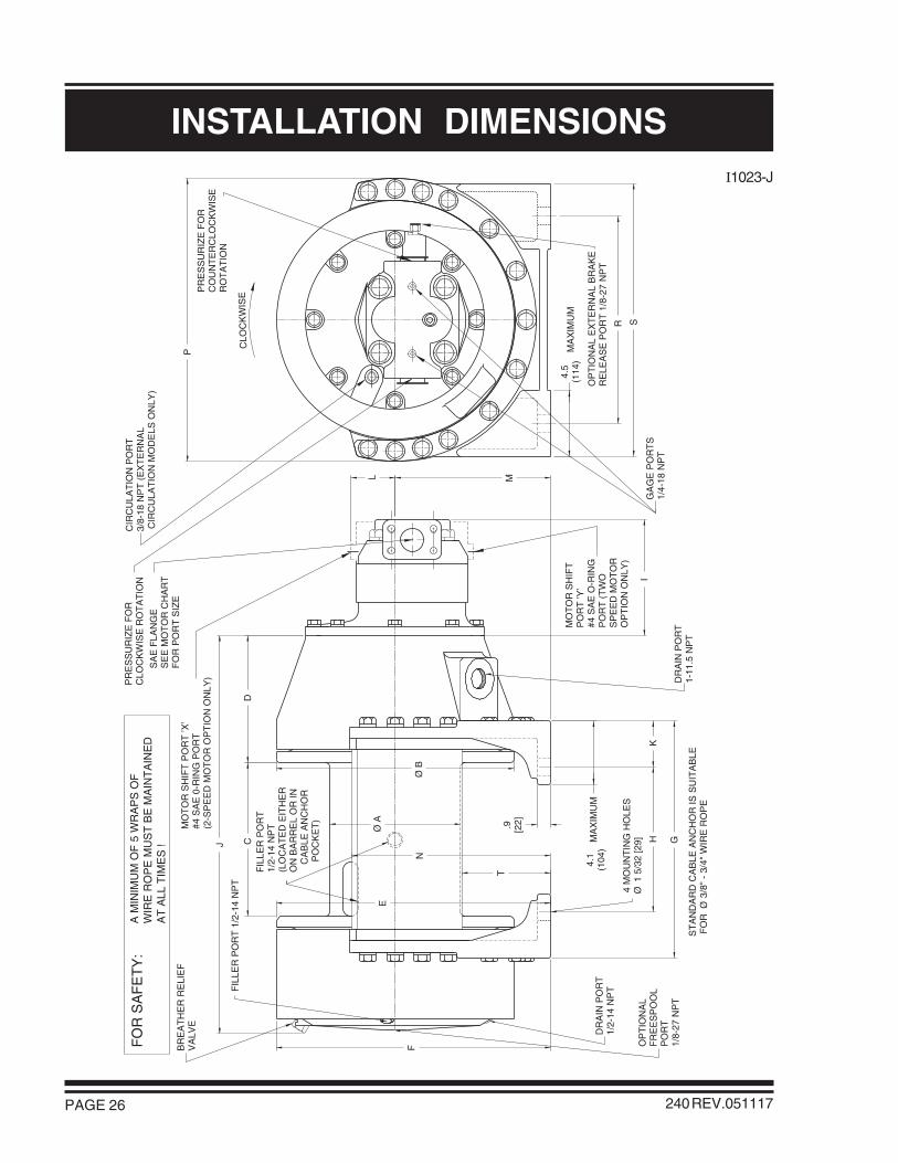
INSTALLATION DIMENSIONS
FIL
LER
PO
RT
1/2-
14 N
PT
(LO
CA
TE
D E
ITH
ER
ON
BA
RR
EL
OR
IN
CA
BLE
AN
CH
OR
P
OC
KE
T)
MA
XIM
UM
4.5
(114
)
MA
XIM
UM
4.1
(104
)
MO
TO
R S
HIF
TP
OR
T ’Y
’#4
SA
E O
-RIN
GP
OR
T (
TW
OS
PE
ED
MO
TO
RO
PT
ION
ON
LY)
MO
TO
R S
HIF
T P
OR
T ’X
’#4
SA
E 0
-RIN
G P
OR
T(2
-SP
EE
D M
OT
OR
OP
TIO
N O
NLY
)
L
GA
GE
PO
RT
S1/
4-18
NP
T
T
FO
R S
AF
ET
Y:
J
I
C
A M
INIM
UM
OF
5 W
RA
PS
OF
WIR
E R
OP
E M
US
T B
E M
AIN
TA
INE
DA
T A
LL T
IME
S !
ST
AN
DA
RD
CA
BLE
AN
CH
OR
IS S
UIT
AB
LE F
OR
3/8"
- 3
/4"
WIR
E R
OP
E
D
F
E
M
HK
OP
TIO
NA
LF
RE
ES
PO
OL
PO
RT
1/8-
27 N
PT
.9 [22]
DR
AIN
PO
RT
1-11
.5 N
PT
CLO
CK
WIS
E
DR
AIN
PO
RT
1/2-
14 N
PTF
ILLE
R P
OR
T 1
/2-1
4 N
PT
BR
EA
TH
ER
RE
LIE
FV
ALV
E
4 M
OU
NT
ING
HO
LES
1
5/3
2 [2
9]
SA
E F
LAN
GE
SE
E M
OT
OR
CH
AR
TF
OR
PO
RT
SIZ
EP
R S
OP
TIO
NA
L E
XT
ER
NA
L B
RA
KE
RE
LEA
SE
PO
RT
1/8
-27
NP
T
PR
ES
SU
RIZ
E F
OR
CLO
CK
WIS
E R
OT
AT
ION
PR
ES
SU
RIZ
E F
OR
CO
UN
TE
RC
LOC
KW
ISE
RO
TA
TIO
N
CIR
CU
LAT
ION
PO
RT
3/8-
18 N
PT
(E
XT
ER
NA
L C
IRC
ULA
TIO
N M
OD
ELS
ON
LY)
G
N

PAGE 27240 REV.030505
INSTALLATION DIMENSIONS
MOTOR GEAR MOTOR PORT SIZE I L
CODE WIDTH SAE 4 BOLT FLANGE
- 042 2.50 8.1 2.5(63.5) (205) (64)
- 101 2.25 7.8 2.5(57.2) (198) (64)
-102 2.00 7.6 2.5(50.8) (192) (64)
1.50 inch- 128 1.75 Code 61 7.3 2.5
(44.5) (186) (64)
- 161 1.00 6.6 2.5(25.4) (167) (64)
- 163 1.25 6.9 2.5(31.2) (173) (64)
- 162 1.50 7.1 2.5(38.1) (180) (64)
Dimensions in inches(Dimensions in millimeters)
COMMERCIAL M365 GEAR MOTORS
-1 8.5 15.5 10.0 8.3 17.9 17.9 15.4 9.430 25.9 3.0 10.13 12.9 18.4 13.500 17.8 5.8
(216) (394) (254) (210) (454) (454) (392) (239.52) (659) (76) (257.2) (329) (468) (342.90) (451) (147)
- 2 13.0 20.0 16.0 8.4 20.8 18.5 22.0 18.500 32.2 1.8 10.75 13.5 23.3 17.250 21.6 6.3
(330) (508) (406) (214) (527) (470) (559) (469.90) (817) (44) (273.1) (342) (591) (438.15) (546) (159)
- 3 8.5 20.0 16.0 8.4 20.8 18.5 22.0 18.500 32.2 1.8 10.75 13.5 23.3 17.250 21.6 6.3
(216) (508) (406) (214) (527) (470) (559) (469.90) (817) (44) (273.1) (342) (591) (438.15) (546) (159)
- 4 8.5 28.0 21.3 8.8 28.8 22.5 28.1 24.187 38.3 1.9 14.75 16.0 31.3 20.500 25.0 8.8
(216) (711) (540) (225) (730) (572) (714) (614.35) (977) (49) (375) (405) (795) (520.70) (635) (223)
DRUMCODE E F GDCA H J K M N P RB S T
Dimensions in inches(Dimensions in millimeters)
COMMERCIAL “WM” TWO-SPEED GEAR MOTORS
HYDRAULIC MOTORS
MOTOR GEAR MOTOR PORT SIZE I L PORT PORT
CODE WIDTH SAE 4 BOLT FLANGE 'X' 'Y'
- 143 2.50 + 2.50 14.7 2.9 DRAIN LOW63.5 + 63.5 (373) (74) SPEED
1.25 inch- 148 2.50 + 2.50 Code 61 14.7 2.9 HIGH DRAIN
63.5 + 63.5 (373) (74) SPEED

PAGE 28
G1017 & G1043-A & G1045
240 REV.001122
ASSEMBLY DRAWING

PAGE 29
APPENDIX A
240 REV.001122
POUNDS(KILONEWTONS)
DRUMCODE
CABLE DRUM SIZESINCHES
(MILLIMETERS)
WIRE ROPE STORAGEFEET
(METERS)FEET/MINUTE
(METERS/MINUTE)
LINE PULLAT MAXIMUMPRESSURE*
BARREL FLANGE LENGTH 7/8 in 3/4 in 5/8 in
-1 8.5 15.5 10.0 113 170 239 18000 11288 122 195 1.3 (216) (394) (254) (34) (52) (73) (80.1) (50.2) (37) (59) (4.9)
-2 13.0 20.0 16.0 251 375 528 12109 8649 182 255 3.7 (330) (508) (406) (77) (114) (161) (53.9) (38.5) (55) (78) (14)
-3 8.5 20.0 16.0 372 500 747 18000 8649 122 255 2.1 (216) (508) (406) (113) (152) (228) (80.1) (38.5) (37) (78) (7.9)
-4 8.5 28.0 21.3 1068 1479 2130 18000 6110 122 360 2.9 (216) (711) (541) (326) (451) (649) (80.1) (27.2) (37) (110) (11.0)
DRUM DRUM DRUM DRUM
LINE SPEEDAT MAXIMUM
VOLUME*
* Performance specifications are based on standard hydraulic motor with 3/4 inch diameter rope.
BARE FULL BARE FULL
LUBRICATINGOIL
VOLUMEREQUIRED
U.S. GALLONS(LITERS)

PAGE 30
APPENDIX B
240 REV.980615
DRUM CODE
ITEMNO.
PARTDESCRIPTION
FINAL HOUSING 21916
21964
21953
25139
25359
21926
25797
21954
21989
- 1 - 2 - 3 - 4
1
1
1
10
26
2
16
2
1
22047
22050
22036
25139
25359
22046
25419
22045
22053
1
1
1
26
42
2
16
2
1
22047
22050
22398
25139
25359
22046
25419
22045
22053
1
1
1
26
42
2
16
2
1
22047
22212
22194
25139
25359
22195
25419
22196
22053
1
1
1
26
42
2
16
2
1
100
340
500
551
553
554
555
556
700
FINAL SUNGEAR
CABLE DRUM
CAPSCREW
5/8 LOCKWASHER
BASE PLATE
CAPSCREW
TIE BAR
BRAKE HOUSING
QTY QTY QTY QTYPART
NUMBERPART
NUMBERPART
NUMBERPART
NUMBER

PAGE 31240 REV.980615
APPENDIX C
PART NUMBERS
BRAKE CODE
ITEMNO.
PARTDESCRIPTION
SHUTTLE
CIRCULATIONVALVE
1/4-18 NPTPIPE PLUG
N/A
20456
N/A
25040
N/A
N/A
N/A
25085
22032
- 3 - 4 - 5 - 6 - 7 - 8 - 9 - 10
20849
20456
N/A
N/A
25622
25374
N/A
25085
22290
20849
20456
N/A
N/A
25622
25374
N/A
25085
22291
N/A
20456
N/A
25040
N/A
N/A
N/A
25085
22033
N/A
N/A
25031
25040
N/A
N/A
26276
N/A
22034
20849
N/A
25031
N/A
25622
25374
26276
N/A
22305
20849
N/A
25031
N/A
25622
25374
26276
N/A
22306
N/A
N/A
25031
25040
N/A
N/A
26276
N/A
22035
802
806
806
807
807
809
929
929
950
1/8-27 NPTPIPE
ADAPTOR
1/8-27 NPTPIPE PLUG
3/8 NPTCAPLUG
MOTORSUB-ASSY
3/8-18 NPTPIPE PLUG
1/8 NPTCAPLUG

PAGE 32
BOLT TORQUE CHART
240 REV.951201
1/4 9 12 5/16 18 24 3/8 32 43 7/16 50 68 1/2 75 102 9/16 110 149 5/8 150 203 3/4 265 359 7/8 420 5691 640 8681 1/8 800 10851 1/4 1000 13561 3/8 1200 16271 1/2 1500 2034
BOLT DIAMETERInches
TORQUElb-ft
TORQUENm
NOTE: Unless otherwise specified, torque bolts per above chart.