instruction booklet ib01900001e effective august 2017 ... · after maintenance, be certain every...
TRANSCRIPT

ContentsDescription Page
1. Introduction . . . . . . . . . . . . . . . . . . . . . . . . . . . 32. Receiving, Handling, and Storage . . . . . . . . . . 53. Equipment Description . . . . . . . . . . . . . . . . . . 54. Additional Publications . . . . . . . . . . . . . . . . . 14
Effective August 2017Instruction Booklet IB01900001E
Instructions for Magnum DST Metal-EnclosedLow-Voltage ARC Resistant Switchgear Assemblies

2
Instruction Booklet IB01900001EEffective August 2017
Instructions for Magnum DS Metal-EnclosedLow-Voltage ARC Resistant Switchgear Assemblies
EATON www.eaton.com
Read and understand these instructions before attempting to unpack, assemble, operate or maintain this type equipment.
NOTICEALL POSSIBLE CONTINGENCIES WHICH MAY ARISE DURING INSTALLATION, OPERATION OR MAINTENANCE, AND ALL DETAILS AND VARIATIONS OF THIS EQUIPMENT DO NOT PURPORT TO BE COVERED BY THESE INSTRUCTIONS.
If further information is desired by purchaser regarding the particular installation, operation or maintenance of particular equipment, con-tact the local Eaton representative.
WARNINGMETAL-ENCLOSED LOW-VOLTAGE ARC-RESISTANT SWITCHGEAR ASSEMBLIES COVERED BY THESE INSTRUCTIONS ARE DESIGNED AND TESTED TO OPERATE WITHIN THEIR NAMEPLATE RATINGS. OPERATION OUTSIDE OF THESE RATINGS MAY CAUSE THE EQUIPMENT TO FAIL RESULTING IN DEATH, SERIOUS INJURY AND/OR PROPERTY DAMAGE. ALL RESPONSIBLE PERSONNEL SHOULD LOCATE THE EQUIPMENT RATING NAMEPLATE AND BE FAMILIAR WITH THE INFORMATION PROVIDED THEREON.
Purpose
This instruction manual is expressly intended to cover the installa-tion, operation and maintenance of Magnum DS® Metal-Enclosed Low-Voltage Arc Resistant Switchgear used with Magnum DS® Power Circuit Breakers.
NOTICETHIS INSTRUCTION MANUAL IS INTENDED TO EMPHASIZE THE FEATURES AND ENHANCEMENTS UNIQUE TO MAGNUM DS ARC RESISTANT SWITCHGEAR. IT IS NOT INTENDED TO BE A COMPLETE MANUAL FOR THE INSTALLATION, OPERATION AND MAINTENANCE OF MAGNUM DS METAL-ENCLOSED LOW-VOLTAGE ASSEMBLIES, BUT IS SUPPLEMENTAL IN NATURE; AND APPENDS THE ORIGINAL ONLY AS DESCRIBED HEREIN. FOR COMPLETE INSTRUCTIONS CONCERNING MAGNUM DS METAL-ENCLOSED LOW-VOLTAGE ASSEMBLIES, SEE IB01901001E.
For application information consult applicable descriptive bulletins, application publications and/or the applicable industry standards.
For installation, operation and maintenance of Low-Voltage Power Circuit Breakers see separate instruction book listed in Section 4.
CAUTIONALL APPLICABLE SAFETY CODES, SAFETY STANDARDS, AND SAFETY REGULATIONS MUST BE STRICTLY ADHERED TO WHEN INSTALLING, OPERATING, OR MAINTAINING THIS EQUIPMENT.
NOTICETHE DANGER, WARNING AND CAUTION MESSAGES INCLUDED AS PART OF THE PROCEDURAL STEPS IN THIS MANUAL ARE FOR PERSONNEL SAFETY AND PROTECTION OF EQUIPMENT FROM DAMAGE. AN EXAMPLE OF A TYPICAL WARNING LABEL HEADING IS SHOWN ABOVE THIS PARAGRAPH TO FAMILIARIZE PERSONNEL WITH THE TYPE OF PRESENTATION. THIS WILL HELP TO ASSURE THAT PERSONNEL ARE ALERT TO THESE MESSAGES. IN ADDITION, THESE MESSAGES ARE ALL UPPER CASE AND BOLDFACE.

3
Instruction Booklet IB01900001EEffective August 2017
Instructions for Magnum DS Metal-EnclosedLow-Voltage ARC Resistant Switchgear Assemblies
EATON www.eaton.com
Section 1: Introduction1.1 General Information
Magnum DS Metal-Enclosed Low-Voltage Arc Resistant Switchgear assemblies with Magnum DS Low-Voltage AC Power Circuit Breakers control and protect power circuits up to and including 600 volts AC and interrupting capacities up to and including 100kA. The switchgear assembly is composed of vertical sections that are arranged to suit the customer’s requirements. Magnum DS switch-gear utilizes a four-cell high structure design consisting of various combinations of Magnum DS Low-Voltage AC Power Circuit Breakers and auxiliary compartments (Figure 1). Bus and cable compartments provide space for connections, maintenance and inspection. These spaces are rear-accessible as a standard, or may be front-accessible as an option. Magnum DS Low-Voltage Arc Resistant Switchgear provides additional protection to the operator in the event of an internal arcing fault. This product has been tested in accordance with IEEE C37.20.7.
WARNINGEATON OFFERS BOTH TYPE 2 AND TYPE 2B LOW-VOLTAGE METAL-ENCLOSED ARC RESISTANT SWITCHGEAR ASSEMBLIES. FOR TYPE 2, THE ARC RESISTANT RATING IS ONLY VALID WHEN ALL DOORS ARE CLOSED AND PROPERLY LATCHED, INCLUDING THE INSTRUMENT COMPARTMENT (CONTROL COMPARTMENT) DOORS. THE TYPE 2B OFFERING ALLOWS FOR THE INSTRUMENT COMPARTMENT (CONTROL COMPARTMENT) DOORS AND THE SECONDARY COMPART-MENT DOORS TO BE OPENED WHILE STILL MAINTAINING THE ARC RESISTANT RATING. IT IS IMPORTANT TO ENSURE THAT THE DOOR IS PROPERLY CLOSED AND LATCHED WHEN AN OPERATOR IS NOT WORKING IN THIS CELL.
See the nameplate affixed to the assembly to determine arc rating type.
This instruction manual contains important procedures and informa-tion pertinent to the receiving, handling, storage, installation, opera-tion and maintenance of Magnum DS Low-Voltage Arc-Resistant Switchgear.
Figure 1. Magnum DS Switchgear Assembly.
NOTICEINFORMATION PROVIDED IN THIS INSTRUCTION MANUAL AND BY OTHER SUPPLIED DOCUMENTATION AND/OR DRAWINGS SHOULD BE READ AND UNDERSTOOD BY ALL PERSONNEL RESPONSIBLE FOR SUPERVISION, OPERATION OR MAINTENANCE. FAMILIARIZATION SHOULD ALWAYS INCLUDE THE CHARACTERISTICS OF EACH PIECE OF EQUIPMENT CONTAINED IN OR MOUNTED ON THE SWITCHGEAR ASSEMBLY. PROPER INSTALLATION, OPERATION AND MAINTENANCE ARE ESSENTIAL TO ASSURE CONTINUED SATISFACTORY SERVICE FROM THE EQUIPMENT. IT SHOULD NOT BE INSTALLED IN PLACES WHERE IT WILL BE REQUIRED TO OPERATE AT VOLTAGE, CURRENTS OR FAULT CAPACITIES. GREATER THAN THOSE FOR WHICH IT WAS DESIGNED, OR WHERE THE ENVIRONMENTAL CONDITIONS ARE DIRTY, CORROSIVE, HUMID OR OTHERWISE HARSH OR UNSUITABLE. (REF. IEEE C37.20.1 AND IEEE C37.20.7 FOR ABNORMAL OPERATION CONDITIONS). THE INFORMATION GIVEN IN THIS MANUAL APPLIES TO NEMA1 (INDOOR) LOW-VOLTAGE ASSEMBLIES UTILIZING MAGNUM DS DRAWOUT POWER CIRCUIT BREAKERS UNLESS OTHERWISE NOTED. FOR OTHER OPTIONS, SEE THE DOCUMENTS LISTED IN SECTION 4.
1.2 Safety Features
Each Magnum DS Assembly is manufactured with built-in interlocks and safety-related features. They are provided to reduce hazards to operating personnel and provide proper operating sequences.
DANGERMETAL-ENCLOSED LOW-VOLTAGE SWITCHGEAR ASSEMBLIES ARE PROVIDED WITH MANY SAFETY FEATURES. NEVERTHELESS, WHEN CONNECTED THEY CONTAIN POWER CIRCUITS WITH HIGH FAULT CAPACITY. THE VOLTAGES AND POWER LEVELS AVAILABLE IN THIS EQUIPMENT MAKE CONTACT WITH BARE CONDUCTORS OR TERMINALS EXTREMELY DANGEROUS, AND IS LIKELY TO BE FATAL. ALL POWER SHOULD BE TURNED OFF OR APPROPRIATE PROTECTIVE EQUIPMENT USED WHEN WORKING ON SUCH EQUIPMENT. IN ADDITION TO THE HAZARDS INHERENT TO THE SWITCHGEAR ASSEMBLY ITSELF, OPERATION BY UNQUALIFIED PERSONS MAY CAUSE INDIRECT DAMAGE TO CONNECTED EQUIPMENT AND INJURY TO OPERATORS OF CONNECTED EQUIPMENT. UNDER NO CIRCUMSTANCE SHOULD THE INTERLOCKS OR OTHER SAFETY FEATURES BE MADE INOPERATIVE OR DISABLED, AS THIS MAY RESULT IN DEATH, BODILY INJURY OR PROPERTY DAMAGE. TO PROTECT PERSONNEL DURING THE INSTALLATION, OPERATION AND MAINTENANCE OF THIS, THE FOLLOWING PRACTICES MUST BE FOLLOWED:

4
Instruction Booklet IB01900001EEffective August 2017
Instructions for Magnum DS Metal-EnclosedLow-Voltage ARC Resistant Switchgear Assemblies
EATON www.eaton.com
1.3 Safety Practices
WARNINGMAGNUM DS LOW-VOLTAGE ARC-RESISTANT SWITCHGEAR ASSEMBLIES ARE COMPLEX, HIGH CURRENT ELECTRICAL EQUIPMENT DESIGNED TO OPERATE WITHIN THE VOLTAGE AND CURRENT LIMITATIONS SHOWN ON THE NAMEPLATE. DO NOT APPLY THIS EQUIPMENT TO SYSTEMS WITH VOLTAGES AND/OR CURRENTS IN EXCESS OF THESE LIMITS.
1. Only qualified electrical personnel familiar with the construction and operation of this equipment and the associated hazards should be permitted to work on such equipment. Additionally, only qualified personnel should be permitted to install or operate such equipment.
2. Always be certain that the primary and secondary circuits are de-energized before attempting any maintenance.
3. For maximum safety, only insert a completely assembled breaker into an energized cell. Front covers are safety features and must be in place when energized.
4. While in the assembly, always ensure that drawout circuit bea-kers are in one of three intended positions: “Connect”, “Test” or “Disconnect”. A circuit breaker permitted to remain in an inter-mediate position could result in control circuits being improperly connected causing other equipment to malfunction.
5. Do not remove access covers unless the circuits to be exposed are de-energized.
6. Use calibrated test equipment of known reliability to confirm that all circuits are de-energized before servicing.
7. After maintenance, be certain every current transformer second-ary circuit is completely connected or shorted.
DANGERIF THE SECONDARY CIRCUIT OF ANY CURRENT TRANSFORMER IS LEFT OPEN WITHOUT LOAD, AND ITS PRIMARY CIRCUIT IS ENERGIZED, A DANGEROUSLY HIGH VOLTAGE IS DEVELOPED ACROSS TRANSFORMER SECONDARY TERMINALS. TO PREVENT DEATH, BODILY INJURY OR ELECTRICAL SHOCK, EITHER DE-ENERGIZE THE CIRCUIT BY OPENING THE BREAKER, OR SHORT CIRCUIT CURRENT TRANSFORMER SECONDARY TERMINALS, BEFORE ENERGIZING THE CIRCUIT AND PROCEEDING WITH MAINTENANCE.
8. Always ensure all assembly hardware is in place and tightened accordingly.
9. Verify that all doors are completely closed and latched.
WARNINGFAILURE TO FOLLOW THESE DIRECTIONS MAY VOID THE IEEE C37.20.7 ARC RESISTANT RATING, AND IN ADDITION RESULT IN DEATH, SERIOUS BODILY INJURY OR PROPERTY DAMAGE.
1.4 Qualified Personnel
For the purpose of operating switchgear assemblies, a person who has been thoroughly trained in the operation of power circuit break-ers and any included instrumentation and who has complete knowl-edge of the loads connected to the assembly may be considered to be a qualified person.
For the purpose of installing, inspecting and maintaining switchgear assemblies, a qualified person MUST also be a qualified electrician, who is thoroughly trained in regard to recognizing and avoiding the hazards inherent to working with electricity and in the proper way to perform such work. The individual must be able to de-energize, clear and lockout/tagout circuits in accordance with established safety practices. In addition, the individual must be equipped with, and trained in the use of, Personal Protective Equipment (PPE) (rub-ber gloves, arc-flash clothes, etc.) for those occasions when it is not possible to de-energize all circuits before doing maintenance work in the area.
WARNINGWHEN WORKING ON ENERGIZED EQUIPMENT, THE ARC RESISTANT RATING WILL BE VOIDED WHEN BOLTS ARE REMOVED AND WHEN DOORS ARE UNLATCHED OR OPEN. THE ONLY EXCEPTION TO THIS RULE EXISTS WHEN INSTRUMENT AND SECONDARY COMPARTMENT DOORS ARE OPENED ON TYPE 2B INSTALLATIONS (SEE SECTION 1.1)
1.5 Other Publications and Documentation
In addition to this instruction manual, other printed information and documentation is supplied with each assembly. This additional infor-mation will include, but not necessarily be limited to, a Magnum DS Low-Voltage Power Circuit Breaker instruction manual, arrangement drawings, and connection diagrams. For additional references see Section 4.

5
Instruction Booklet IB01900001EEffective August 2017
Instructions for Magnum DS Metal-EnclosedLow-Voltage ARC Resistant Switchgear Assemblies
EATON www.eaton.com
Section 2: Receiving, Handling & Storage
NOTICEFOR COMPLETE RECEIVING, HANDLING AND STORAGE INSTRUCTIONS, SEE SECTION 2 OF THE PRIMARY INSTRUCTION BOOK IB01901001E, REFERENCED ELSEWHERE IN THIS PUBLICATION. INSTRUCTIONS WHICH FOLLOW EMPHASIZE THE UNIQUE FEATURES ASSOCIATED WITH MAGNUM DS ARC RESISTANT SWITCHGEAR.
2.1 Shipping Skid Removal
The wooden shipping skid bolted to the bottom of an indoor assem-bly must be removed before the equipment is placed in its perma-nent location. Lag bolts attach the shipping skids to the assembly from the inside: typically six bolts per vertical section of rear-acces-sible assemblies; four bolts per vertical section of front-accessible assemblies. The holes that remain in the equipment after the skids and lag bolts are removed are used in securing the indoor assembly permanently in position. See Section 4 of IB01901001E and base plan drawing 4A37896 for intended lag locations for various assem-bly configurations.
To access the rearmost lag bolts on rear-accessible Arc Resistant switchgear, it will be necessary to remove the dynamic flap cage from the rear frame. To remove the cage, remove the two screws that hold the cage in place (Figure 2). Take care not to lose the screws as these will be required when reinstalling the cage. Remove the shipping lag bolts. After permanent installation, rein-stall the cage using the original screws. Avoid over tightening the screws during installation as this could result in stripping of the threads in the steel. It is crucial to reinstall the cage to ensure the dynamic flap will perform as required for the arc resistant rating. Verify that the dynamic flap floats freely after installation of the cage.
WARNINGFAILURE TO REINSTALL ANY DYNAMIC FLAP ASSEMBLY AS DESCRIBED ABOVE WILL VOID THE IEEE C37.20.7 ARC RESISTANT RATING.
For front-accessible Arc Resistant Switchgear, the dynamic flap cage does not obstruct access to the lag bolts.
Figure 2. Rear-Frame Dynamic Flap Cage Assembly.
WARNINGTHE ARC RESISTANT RATING IS ONLY VALID WHEN ALL FLOORPLATES ARE PRESENT AND PROPERLY ATTACHED. FLOORPLATES REMOVED DURING INSTALLATION OF THE SWITCHGEAR, INSTALLATION OF CONDUIT HUBS (FOR BOTTOM CABLE ENTRY) OR FOR ANY OTHER PURPOSE MUST BE REINSTALLED PRIOR TO ENERGIZING THE EQUIPMENT. FAILURE TO DO SO WILL VOID THE IEEE C37.20.7 ARC RESISTANT RATING.
Section 3: Equipment Description3.1 General Description
The following descriptions apply to standard low-voltage metal-enclosed Arc Resistant construction and wiring. Special features and control schemes are often incorporated per customer specifications. These special features are evident and portrayed on the drawings and diagrams for the specific assembly received. Instructions on included apparatus such as relays, instruments, control switches and circuit breakers are included elsewhere in separate instruction books or sheets.
Each low-voltage (600 volts and below) metal enclosed Arc Resistant switchgear assembly is factory assembled and tested. It is designed to require a minimum amount of labor for installation.
Each Arc Resistant assembly is a stationary structure with a mini-mum width of 60”, consisting of vertical sections mechanically and electrically joined to make a single coordinated installation.
In rear-accessible units, a vertical section consists of three major divisions: the front breaker compartment, bus compartment, and cable compartment. In front-accessible units, the three divisions are redistributed between a pair of vertical sections: front breaker com-partment/bus compartment in one portion; cable compartment/bus compartment in the remaining portion.
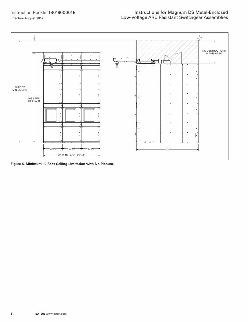
When no exhaust plenum and duct is installed (see Section 3.6), the Arc Resistant assembly must be installed such that no obstruction resides above the assembly at a distance less than 10 ft (3.05 m) from the base of the assembly (Figure 5). This includes ceilings, as well as cable trays or any other obstruction that, in the event of an internal arc, would impede the escape of internal pressure, gasses and debris through the roof-mounted pressure relief flaps.
Arc Resistant switchgear has many specialized components designed to protect the operator in the unlikely event an electrical arcing event occurs within the switchgear. These components are designed to prevent any arc gasses from escaping around the acces-sible perimeter of the enclosure and to direct these gases out the top of the enclosure via pressure relief flaps or an exhaust duct.
DANGERFOR TYPE 2, THE ARC RESISTANT RATING IS ONLY VALID WHEN ALL DOORS ARE CLOSED AND PROPERLY LATCHED, INCLUDING THE INSTRUMENT COMPARTMENT (CONTROL COMPARTMENT) DOORS. THE TYPE 2B OFFERING ALLOWS FOR THE INSTRUMENT COMPARTMENT (CONTROL COMPARTMENT) DOORS TO BE OPENED WHILE STILL MAINTAINING THE ARC RESISTANT RATING. IT IS IMPORTANT TO ENSURE THAT THE DOOR IS PROPERLY CLOSED AND LATCHED WHEN AN OPERATOR IS NOT WORKING IN THIS CELL.
3.2 Instrument (Auxiliary) Components
Instrument compartments are used to mount passive and active control components and other auxiliary devices. The compartment has a hinged front door that may be used for mounting a variety of devices.
3.3 Breaker Cells (Draw-Out)
CAUTIONFAILURE TO HAVE ANY DRAWOUT BREAKER COMPLETELY IN THE DISCONNECT POSITION BEFORE RACKIN-IN CAN CAUSE SERIOUS EQUIPMENT DAMAGE. ENSURE THAT THE BREAKER REACHES A POSITIVE STOP WHEN INSERTING INTO THE CELL PRIOR TO RACKING.

6
Instruction Booklet IB01900001EEffective August 2017
Instructions for Magnum DS Metal-EnclosedLow-Voltage ARC Resistant Switchgear Assemblies
EATON www.eaton.com
Figure 3. Arc Resistant Switchgear Side Elevation (Rear-Access) With Plenum.
D72
[1828]78
[1981]84
[2133]90
[2286]
A22
[550]28
[702]34
[855] 40
[1007]
91.9[2336]
117.1[2972]
"D"
"A" 26.1[663]
98.7[2508]
27.0[685]

7
Instruction Booklet IB01900001EEffective August 2017
Instructions for Magnum DS Metal-EnclosedLow-Voltage ARC Resistant Switchgear Assemblies
EATON www.eaton.com
Figure 4. Arc Resistant Switchgear Side Elevation (Front-Access) With Plenum.
D72
[1828]78
[1981]84
[2133]90
[2286]
A22
[550]28
[702]34
[855] 40
[1007]
91.9[2336]
117.1[2972]
"D"
"A" 26.1[663]
98.7[2508]
27.0[685]
8
Instruction Booklet IB01900001EEffective August 2017
Instructions for Magnum DS Metal-EnclosedLow-Voltage ARC Resistant Switchgear Assemblies
EATON www.eaton.com
Figure 5. Minimum 10-Foot Ceiling Limitation with No Plenum.
105.2 TOP OF FLAPS
10 FOOTMIN CEILING
NO OBSTRUCTIONSIN THIS AREA.
7222.00
66.00 MIN ARC LINE-UP
22.00 22.00
9
Instruction Booklet IB01900001EEffective August 2017
Instructions for Magnum DS Metal-EnclosedLow-Voltage ARC Resistant Switchgear Assemblies
EATON www.eaton.com
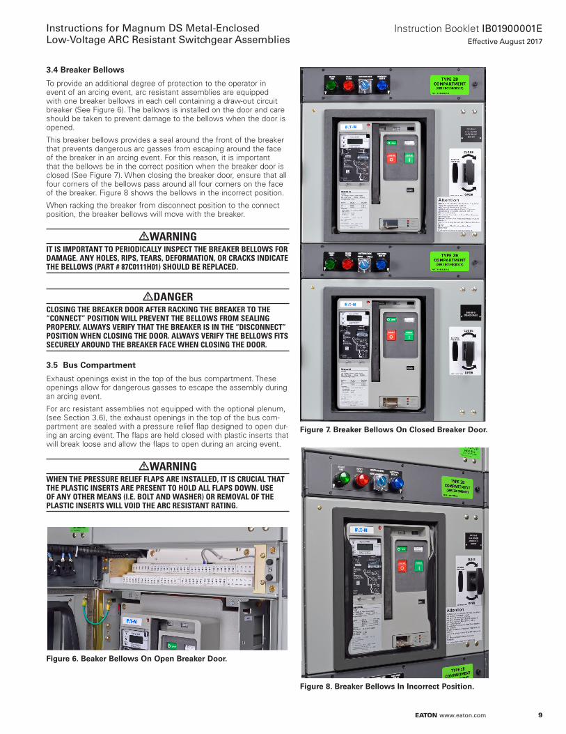
3.4 Breaker Bellows
To provide an additional degree of protection to the operator in event of an arcing event, arc resistant assemblies are equipped with one breaker bellows in each cell containing a draw-out circuit breaker (See Figure 6). The bellows is installed on the door and care should be taken to prevent damage to the bellows when the door is opened.
This breaker bellows provides a seal around the front of the breaker that prevents dangerous arc gasses from escaping around the face of the breaker in an arcing event. For this reason, it is important that the bellows be in the correct position when the breaker door is closed (See Figure 7). When closing the breaker door, ensure that all four corners of the bellows pass around all four corners on the face of the breaker. Figure 8 shows the bellows in the incorrect position.
When racking the breaker from disconnect position to the connect position, the breaker bellows will move with the breaker.
WARNINGIT IS IMPORTANT TO PERIODICALLY INSPECT THE BREAKER BELLOWS FOR DAMAGE. ANY HOLES, RIPS, TEARS, DEFORMATION, OR CRACKS INDICATE THE BELLOWS (PART # 87C0111H01) SHOULD BE REPLACED.
DANGERCLOSING THE BREAKER DOOR AFTER RACKING THE BREAKER TO THE “CONNECT” POSITION WILL PREVENT THE BELLOWS FROM SEALING PROPERLY. ALWAYS VERIFY THAT THE BREAKER IS IN THE “DISCONNECT” POSITION WHEN CLOSING THE DOOR. ALWAYS VERIFY THE BELLOWS FITS SECURELY AROUND THE BREAKER FACE WHEN CLOSING THE DOOR.
3.5 Bus Compartment
Exhaust openings exist in the top of the bus compartment. These openings allow for dangerous gasses to escape the assembly during an arcing event.
For arc resistant assemblies not equipped with the optional plenum, (see Section 3.6), the exhaust openings in the top of the bus com-partment are sealed with a pressure relief flap designed to open dur-ing an arcing event. The flaps are held closed with plastic inserts that will break loose and allow the flaps to open during an arcing event.
WARNINGWHEN THE PRESSURE RELIEF FLAPS ARE INSTALLED, IT IS CRUCIAL THAT THE PLASTIC INSERTS ARE PRESENT TO HOLD ALL FLAPS DOWN. USE OF ANY OTHER MEANS (I.E. BOLT AND WASHER) OR REMOVAL OF THE PLASTIC INSERTS WILL VOID THE ARC RESISTANT RATING.
Figure 6. Beaker Bellows On Open Breaker Door.
Figure 7. Breaker Bellows On Closed Breaker Door.
Figure 8. Breaker Bellows In Incorrect Position.

10
Instruction Booklet IB01900001EEffective August 2017
Instructions for Magnum DS Metal-EnclosedLow-Voltage ARC Resistant Switchgear Assemblies
EATON www.eaton.com
Figure 9. Plenum Installation (Rear-Access Shown, Front-Access similar).
DETAIL A
A
5/16-18 BASKET NUTS
IN PLENUM MOUNTING
PLATE.
22" WIDE SECTION SHOWN;
OTHER SECTION WIDTHS SIMILAR
PLENUM ASSEMBLY
TO MOUNT REAR
OF PLENUM USE
5/16-18 X 1.0 LG
THREAD CUTTER
BOLTS.
TYPICAL HARDWARE
INSTALATION OF PLENUM
USE ALL 5/16 GRADE 5
25A3397

11
Instruction Booklet IB01900001EEffective August 2017
Instructions for Magnum DS Metal-EnclosedLow-Voltage ARC Resistant Switchgear Assemblies
EATON www.eaton.com
Figure 10. Hardware Connection Plenum Sections.
3.6 Arc Plenum & Exhaust Duct (Optional)
The arc plenum and exhaust duct can be included with the Arc Resistant assembly as an added degree of protection to prevent inhalation of the harmful gasses associated with electrical arcs. During an arcing event, the high temperatures generated are suf-ficient enough to vaporize all materials in the vicinity of the arc. This includes copper, steel, plastic and coating materials used on all com-ponents. By utilizing an arc plenum and exhaust duct system, these harmful gasses can be channeled from the room in which the gear is installed and into a different location away from personnel.
3.6.1 Arc Plenum
The arc plenum will arrive separately from the switchgear, but assembled in the same shipping section widths as the switchgear assembly. Each plenum section will require mounting on top of the switchgear assembly after the switchgear sections are connected and in permanent position. To mount the plenum, place it on top of the gear such that the shorter vertical side faces the front of the switchgear. Holes for mounting the plenum will be available on the top of the switchgear assembly. Three mounting holes are located in the front of each vertical section, and five are located to the rear. Install the bolt / lock washer / flat washer combination provided in the front of the plenum as shown in Figure 9. Use the thread cutting screws provided (without washers) to mount the rear of the plenum. To connect plenum sections use the hardware combination shown in Figure 10 to fill EACH mounting hole.
3.6.2 Exhaust Duct
Exhaust ducts permit harmful gasses to be channeled from the room in which the gear is installed into a different location away from personnel. Ducts can be a variety of lengths and connected to the plenum from either side or from the rear.
3.6.2.1 Side Exit Exhaust Duct
After mounting the plenum, the exhaust duct can be installed. To attach the exhaust duct to the plenum, follow the hardware con-nection type shown in Figure 11 to mount three sides of the duct mounting brackets to the plenum. For the lower flange, utilize the included self drilling screw to connect the lower side of the plenum to the switchgear structure.

12
Instruction Booklet IB01900001EEffective August 2017
Instructions for Magnum DS Metal-EnclosedLow-Voltage ARC Resistant Switchgear Assemblies
EATON www.eaton.com
Figure 11. Exhaust Duct Connection to Plenum (Side Exit).
3.6.2.2 Rear Exit Exhaust Duct
For rear exit exhaust duct, a special section of plenum will be pro-vided with the opening for the duct facing away from the front of the gear (Figure 12). Mounting holes are provided with cage nuts pre-installed on all four sides of the opening to receive bolt and washer hardware when connecting the exhaust duct.
HARDWARE FOR CONNECTING
TOP AND SIDES OF
EXHAUST DUCT TO PLENUM
USE 5/16-18 GRADE 5
HARDWARE FOR CONNECTING
BOTTOM OF EXHAUST DUCT TO
PLENUM USE 1/4-20 STAINLESS
STEEL SELF-DRILLING SCREWS.
25A3397
PLENUM ASSEMBLY
DUCT ASSEMBLY
Figure 12. Exhaust Duct Connection to Plenum (Rear Exit).
REAR VIEW
SPECIAL PLENUM SECTION
FOR REAR EXHAUST DUCT
5/16-18 CAGE NUTS IN PLENUM
USE 5/16-18 BOLTS, LOCK, & WASHERS
TO ATTACH EXHAUST DUCT (NOT SHOWN)
EXHAUST DUCT FLANGE CONNECTION
(EXHAUST DUCT NOT SHOWN FOR CLARITY)
25A3397
13
Instruction Booklet IB01900001EEffective August 2017
Instructions for Magnum DS Metal-EnclosedLow-Voltage ARC Resistant Switchgear Assemblies
EATON www.eaton.com
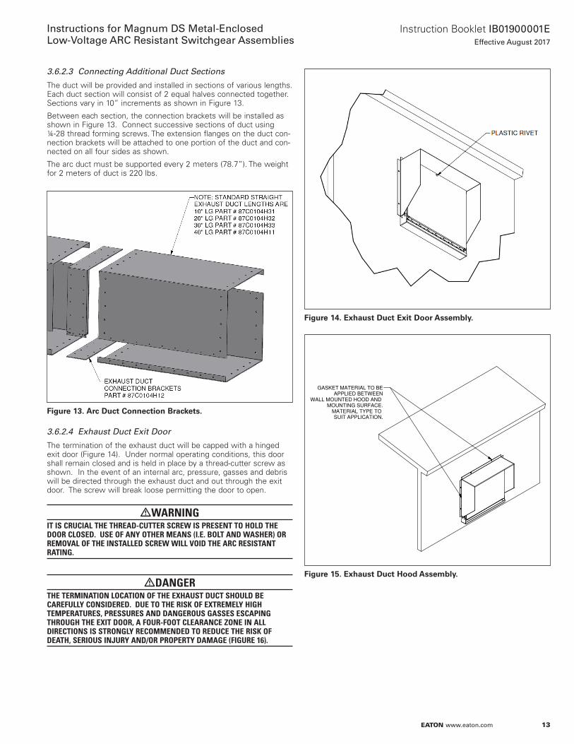
3.6.2.3 Connecting Additional Duct Sections
The duct will be provided and installed in sections of various lengths. Each duct section will consist of 2 equal halves connected together. Sections vary in 10” increments as shown in Figure 13.
Between each section, the connection brackets will be installed as shown in Figure 13. Connect successive sections of duct using ¼-28 thread forming screws. The extension flanges on the duct con-nection brackets will be attached to one portion of the duct and con-nected on all four sides as shown.
The arc duct must be supported every 2 meters (78.7”). The weight for 2 meters of duct is 220 lbs.
Figure 13. Arc Duct Connection Brackets.
3.6.2.4 Exhaust Duct Exit Door
The termination of the exhaust duct will be capped with a hinged exit door (Figure 14). Under normal operating conditions, this door shall remain closed and is held in place by a thread-cutter screw as shown. In the event of an internal arc, pressure, gasses and debris will be directed through the exhaust duct and out through the exit door. The screw will break loose permitting the door to open.
WARNINGIT IS CRUCIAL THE THREAD-CUTTER SCREW IS PRESENT TO HOLD THE DOOR CLOSED. USE OF ANY OTHER MEANS (I.E. BOLT AND WASHER) OR REMOVAL OF THE INSTALLED SCREW WILL VOID THE ARC RESISTANT RATING.
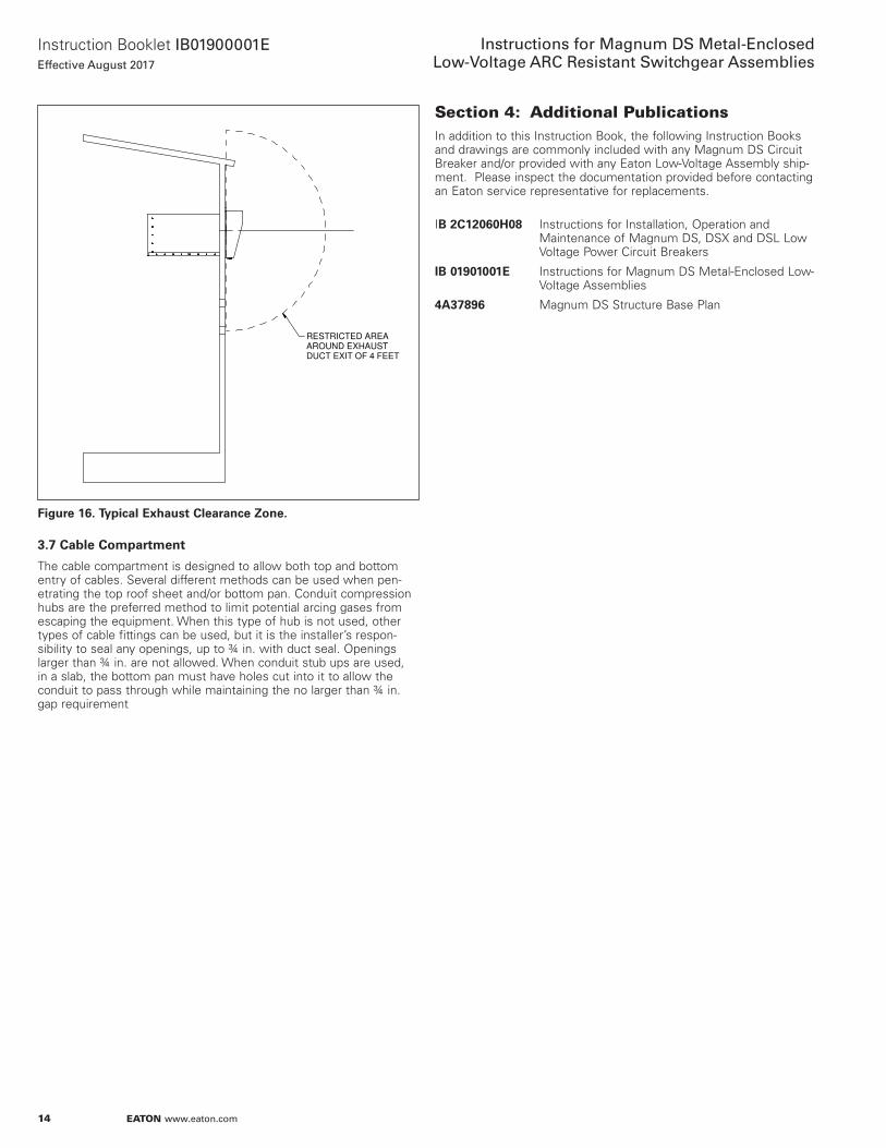
DANGERTHE TERMINATION LOCATION OF THE EXHAUST DUCT SHOULD BE CAREFULLY CONSIDERED. DUE TO THE RISK OF EXTREMELY HIGH TEMPERATURES, PRESSURES AND DANGEROUS GASSES ESCAPING THROUGH THE EXIT DOOR, A FOUR-FOOT CLEARANCE ZONE IN ALL DIRECTIONS IS STRONGLY RECOMMENDED TO REDUCE THE RISK OF DEATH, SERIOUS INJURY AND/OR PROPERTY DAMAGE (FIGURE 16).
Figure 14. Exhaust Duct Exit Door Assembly.
Figure 15. Exhaust Duct Hood Assembly.
DWG NO
MODEL REV
SHEET OF
TITLE
ALL REV. NOTES
LISTED ON SHT. 1REVMODEL FILENAME
T.BLK
REV-4A
25A3418
8 11 2
PLENUM WALL CUTOUT
25A3418G02.iam 1
OD ON.
GASKET MATERIAL TO BE
APPLIED BETWEEN
WALL MOUNTED HOOD AND
MOUNTING SURFACE.
MATERIAL TYPE TO
SUIT APPLICATION.
14
Instruction Booklet IB01900001EEffective August 2017
Instructions for Magnum DS Metal-EnclosedLow-Voltage ARC Resistant Switchgear Assemblies
EATON www.eaton.com
Figure 16. Typical Exhaust Clearance Zone.
3.7 Cable Compartment
The cable compartment is designed to allow both top and bottom entry of cables. Several different methods can be used when pen-etrating the top roof sheet and/or bottom pan. Conduit compression hubs are the preferred method to limit potential arcing gases from escaping the equipment. When this type of hub is not used, other types of cable fittings can be used, but it is the installer’s respon-sibility to seal any openings, up to ¾ in. with duct seal. Openings larger than ¾ in. are not allowed. When conduit stub ups are used, in a slab, the bottom pan must have holes cut into it to allow the conduit to pass through while maintaining the no larger than ¾ in. gap requirement
DWG NO
MODEL REV
SHEET OF
TITLE
ALL REV. NOTES
LISTED ON SHT. 1REVMODEL FILENAME
T.BLK
REV-4A
25A3418
10 10 2
New Plenum -1.iam
RESTRICTED AREA
AROUND EXHAUST
DUCT EXIT OF 4 FEET
EXHAUST DUCT
RESTRICTED AREA.
Section 4: Additional PublicationsIn addition to this Instruction Book, the following Instruction Books and drawings are commonly included with any Magnum DS Circuit Breaker and/or provided with any Eaton Low-Voltage Assembly ship-ment. Please inspect the documentation provided before contacting an Eaton service representative for replacements.
IB 2C12060H08 Instructions for Installation, Operation and Maintenance of Magnum DS, DSX and DSL Low Voltage Power Circuit Breakers
IB 01901001E Instructions for Magnum DS Metal-Enclosed Low- Voltage Assemblies
4A37896 Magnum DS Structure Base Plan

15
Instruction Booklet IB01900001EEffective August 2017
Instructions for Magnum DS Metal-EnclosedLow-Voltage ARC Resistant Switchgear Assemblies
EATON www.eaton.com
Notes:
EatonElectrical Sector1000 Eaton BoulevardCleveland, OH 45122United States877-ETN-CARE (877-386-2273)Eaton.com
© 2017 Eaton All Rights ReservedPrinted in USAPublication No. IB01900001E / TBG000649August 2017
Eaton is a registered trademark.
All other trademarks are property of their respective owners.
Instruction Booklet IB01900001EEffective August 2017
Instructions for Magnum DS Metal-EnclosedLow-Voltage ARC Resistant Switchgear Assemblies
This Instruction Booklet is published solely for information purposes and should not be considered all-inclusive. If further information is required, you should consult an authorized Eaton sales representa-tive.
The sale of the product shown in this literature is subject to the terms and conditions outlined in appropriate Eaton selling policies or other contractual agreement between the parties. This literature is not intended to and does not enlarge or add to any such contract. The sole source governing the rights and remedies of any purchaser of this equipment is the contract between the purchaser and Eaton.
NO WARRANTIES, EXPRESSED OR IMPLIED, INCLUDING WARRANTIES OF FITNESS FOR A PARTICULAR PURPOSE OR MERCHANTABILITY, OR WARRANTIES ARISING FROM COURSE OF DEALING OR USAGE OF TRADE, ARE MADE REGARDING THE INFORMATION, RECOMMENDATIONS, AND DESCRIPTIONS CONTAINED HEREIN.
In no event will Eaton be responsible to the purchaser or user in contract, in tort (including negligence), strict liability or otherwise for any special, indirect, incidental or consequential damage or loss whatsoever, including but not limited to damage or loss of use of equipment, plant or power system, cost of capital, loss of power, additional expenses in the use of existing power facilities, or claims against the purchaser or user by its customers resulting from the use of the information, recommendations and description contained herein.